

Page 1
MOTOMESH Duo 2.1
Network Setup and Installation Guide
Motorola
1303 E. Algonquin Rd.
Schaumburg, IL
60196 USA
www.motorola.com/mesh
847-576-5000
Version 1A
September 2008
Page 2

This page intentionally left blank.
ii
Page 3

Copyrights
The Motorola products described in this document may include copyrighted Motorola computer programs. Laws in the
United States and other countries reserve for Motorola certain exclusive rights for copyrighted computer programs.
Accordingly, any copyrighted Motorola computer programs contained in the Motorola products described in this
document may not be copied or reproduced in any manner without the express written permission of Motorola.
Furthermore, the purchase of Motorola products shall not be deemed to grant either directly or by implication,
estoppels or otherwise, any license under the copyrights, patents or patent applications of Motorola, except for the
normal nonexclusive, royalty-free license to use that arises by operation of law in the sale of a product.
Disclaimer
Please note that certain features, facilities and capabilities described in this document may not be applicable to or
licensed for use on a particular system, or may be dependent upon the characteristics of a particular mobile
subscriber unit or configuration of certain parameters. Please refer to your Motorola contact for further information.
Trademarks
Motorola, the Motorola logo, and all other trademarks identified as such herein are trademarks of Motorola, Inc. All
other product or service names are the property of their respective owners.
Copyrights
© 2008 Motorola, Inc. All rights reserved. No part of this document may be reproduced, transmitted, stored in a
retrieval system, or translated into any language or computer language, in any form or by any means, without the
prior written permission of Motorola, Inc.
iii
Page 4

This page intentionally left blank.
iv
Page 5

Table
Of
Contents
Contents
.............................................
.
.
.
.
Chapter 1: System Overview ...........................................................................................................1-1
MOTOMESH Duo 2.1 Network Components ........................................................................................1-2
Intelligent Access Point.................................................................................................................1-2
Mesh Wireless Router...................................................................................................................1-3
Supporting Networking Equipment ...............................................................................................1-3
Chapter 2: Network Setup................................................................................................................2-5
Small System Reference Design...........................................................................................................2-5
Network Requirements ..........................................................................................................................2-5
Network Servers................................................................................................................................2-5
One Point Wireless Manager Server ............................................................................................2-6
RADIUS - (Optional)......................................................................................................................2-6
EAP-TTLS Secure Mesh ..........................................................................................................2-7
Network Device Ethernet Interconnectivity........................................................................................2-7
IP Addressing Plan............................................................................................................................2-8
Layer 3 Switch ...................................................................................................................................2-9
Overview .......................................................................................................................................2-9
IP Directed Broadcasts .................................................................................................................2-9
VLAN Setup ................................................................................................................................2-10
VLAN Examples..........................................................................................................................2-11
MOTOMESH Duo Device Defaults .................................................................................................2-13
Preparing the One Point Wireless Manager Server........................................................................2-14
Minimum Software Requirements...............................................................................................2-15
Red Hat Linux Installation ...........................................................................................................2-15
Preparing the Windows 2003 Server and Juniper RADIUS............................................................2-22
Installing Windows 2003 Server..................................................................................................2-22
Driver Installation for HP DL360 G5 Server ...........................................................................2-23
Installing Windows 2003 Support Tools .................................................................................2-24
Microsoft Certificate Authority Services ......................................................................................2-24
Configuring Automatic Certificate Issuing ..............................................................................2-26
Requesting a Server Certificate..............................................................................................2-26
Authentication Server Configuration ...........................................................................................2-28
Juniper Steel-Belted RADIUS.................................................................................................2-28
Exporting Certificates..............................................................................................................2-28
Installing Certificates...............................................................................................................2-29
Configuring EAP Settings .......................................................................................................2-30
v
Page 6

Configuring a Radius Client....................................................................................................2-31
Configure RADIUS User.........................................................................................................2-31
Trusted Root Certificate ..............................................................................................................2-32
Authenticator (R0KH) Configuration ...........................................................................................2-32
Chapter 3: MOTOMESH Duo Hardware ..........................................................................................3-1
MOTOMESH Duo Enclosure.................................................................................................................3-1
Enclosure Side 1 ...............................................................................................................................3-2
Enclosure Side 2 ...............................................................................................................................3-3
Mounting Bracket...............................................................................................................................3-4
Personality Plug.....................................................................................................................................3-5
Standard / Canopy Connect PoE Plug Usage Information ...............................................................3-5
Reset Plug Usage Information ..........................................................................................................3-6
Connecting Power .................................................................................................................................3-6
Flying Lead Power Cable ..................................................................................................................3-7
Power Tap Adapter............................................................................................................................3-8
Power Consumption ..........................................................................................................................3-9
Ethernet Adapter Cable .........................................................................................................................3-9
Antenna ...............................................................................................................................................3-10
BandPass Filter ...............................................................................................................................3-11
Chapter 4: Site Selection and Deployment Guidelines.................................................................4-1
Preparation ............................................................................................................................................4-1
Hardware and Tools ..............................................................................................................................4-2
Device Assembly ...................................................................................................................................4-3
Site Selection Guidelines.....................................................................................................................4-15
Site Surveys ....................................................................................................................................4-15
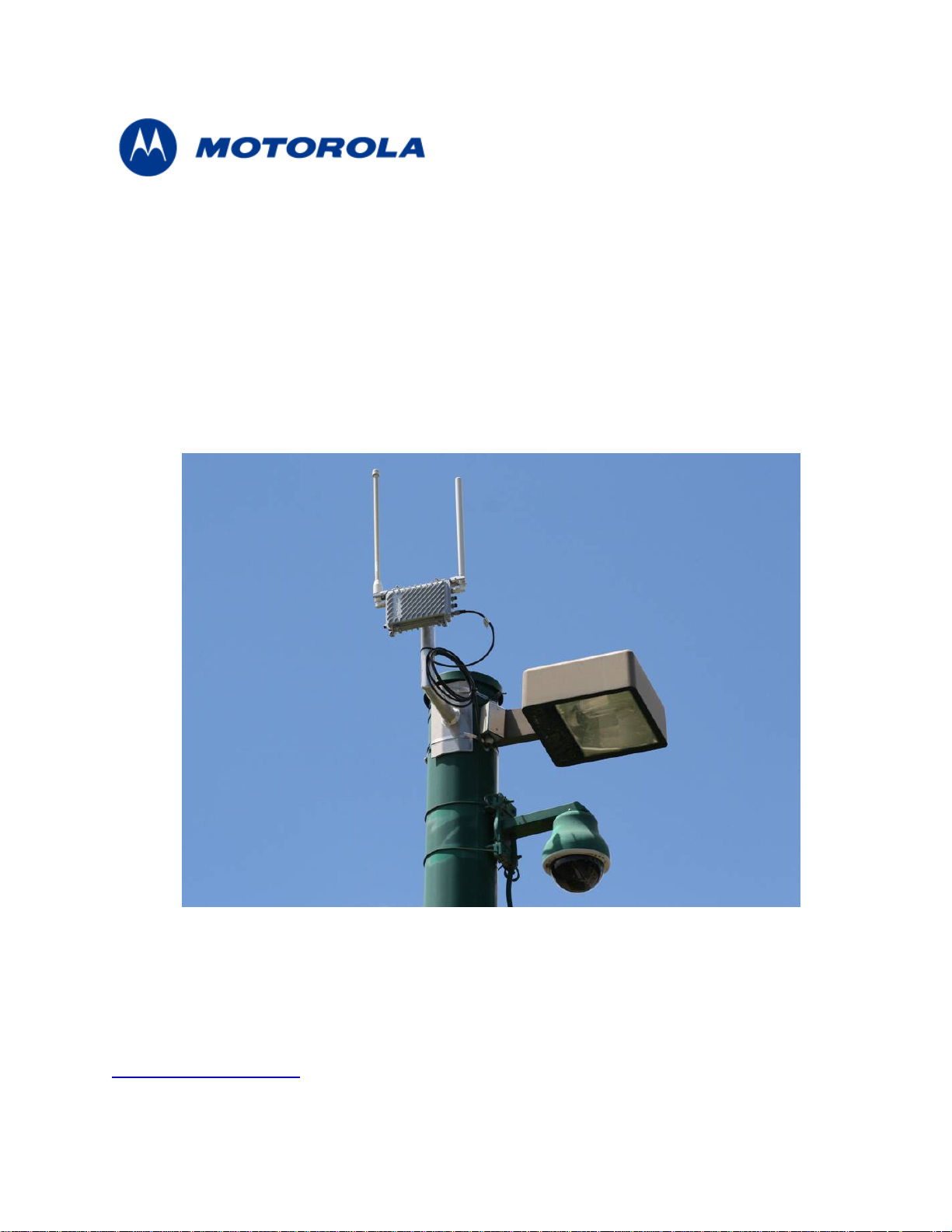
Device Mounting..............................................................................................................................4-16
Street Lights ................................................................................................................................4-17
Roof Mount..................................................................................................................................4-17
Antenna Height....................................................................................................................................4-18
Mounting Examples .............................................................................................................................4-19
Chapter 5: Customer Information....................................................................................................5-1
Customer Service Information...............................................................................................................5-1
Obtaining Support..............................................................................................................................5-2
System Information .......................................................................................................................5-2
Return Material Request ...............................................................................................................5-2
Returning FREs.............................................................................................................................5-3
Software License Terms and Conditions...............................................................................................5-3
Chapter 6: Certification and Safety Information............................................................................6-1
FCC Regulatory Information..................................................................................................................6-1
Federal Communications Commission (FCC) Statement .................................................................6-1
Safety Information for the MOTOMESH Products.................................................................................6-2
FCC Radiation Exposure Statement .................................................................................................6-2
Safety Certification.................................................................................................................................6-2
Regulatory Requirements and Legal Notices........................................................................................6-3
vi
Page 7

Regulatory Requirements for CEPT Member States ........................................................................6-3
European Union Notification..............................................................................................................6-4
European Union Notification 5.7GHz Product ..............................................................................6-4
Annex 6 – Instructions for use (regulatory content) MOTOMESH 2.4/5.8 GHz Radio .....................6-5
European Union Notification .........................................................................................................6-5
Equipment Disposal...........................................................................................................................6-6
UK Notification...................................................................................................................................6-6
Belgium Notification...........................................................................................................................6-6
Luxembourg Notification....................................................................................................................6-6
Czech Republic Notification...............................................................................................................6-7
Norway Notification............................................................................................................................6-7
Greece Notification............................................................................................................................6-7
DECLARATION OF CONFORMITY..................................................................................................6-8
EU Declaration of Conformity for RoHS Compliance......................................................................6-10
CMM Labeling and Disclosure Table...................................................................................................6-11
Chapter 7: Index................................................................................................................................7-1
Chapter 8: Glossary..........................................................................................................................8-1
Chapter 9: Appendix A:....................................................................................................................9-1
IP Directed Broadcast Feature ..............................................................................................................9-1
Enabling the IP Directed Broadcast Feature.....................................................................................9-1
Cisco 3750 L3 Switch Core Configuration File..................................................................................9-2
Equipment Specifications ......................................................................................................................9-8
Wiring Instructions ...............................................................................................................................9-10
US Power Connector Wiring Instructions........................................................................................9-10
Part I – Power Connector Parts ..................................................................................................9-10
Part II – Power Cable with Flying Leads.....................................................................................9-11
Part III – Power Connector and Cable Assembly Instructions....................................................9-11
European Power Connector Wiring Instructions .............................................................................9-14
Part I – Power Connector Parts ..................................................................................................9-14
Part II – Power Cable with Flying Leads.....................................................................................9-16
Part III – Power Connector and Cable Assembly Instructions....................................................9-16
Australian Wiring Instructions..........................................................................................................9-20
Part I – Power Connector Parts ..................................................................................................9-20
Part II – Power Cable with Flying Leads.....................................................................................9-23
Part III – Power Connector and Cable Assembly Instructions....................................................9-23
Backdoor Access to a MOTOMESH Duo Device via the Web Interface.............................................9-26
MOTOMESH Duo Infrastructure Device Labels..............................................................................9-31
Dynamic Frequency Selection.............................................................................................................9-32
Auto-Channel Selection...................................................................................................................9-32
Preferred Channel List.....................................................................................................................9-32
Scan Triggers ..................................................................................................................................9-32
The Scan .........................................................................................................................................9-32
vii
Page 8

List
Of
Figures
List of Figures
.............................................
.
.
.
.
Figure 1-1 2.4 / 5.8 GHz Mesh Network Example .................................................................................1-4
Figure 2-1 HP DL360 G5 server ............................................................................................................2-6
Figure 2-2 Ethernet connectivity between network servers and 3750 L3 Switch..................................2-7
Figure 2-3 Cisco 3750 L3.......................................................................................................................2-9
Figure 2-4 L3 Switch for MOTOMESH Duo 2.1 - VLAN View .............................................................2-11
Figure 2-5 VLAN Example 1 ................................................................................................................2-12
Figure 2-6 VLAN Example 2 ................................................................................................................2-13
Figure 3-1 Enclosure Side 1 ..................................................................................................................3-2
Figure 3-2 Enclosure Side 2 ..................................................................................................................3-3
Figure 3-3 Pivot Bracket ........................................................................................................................3-4
Figure 3-4 Select Port ............................................................................................................................3-5
Figure 3-5 12ft AC Flying Lead Cable (3071331H01) ...........................................................................3-7
Figure 3-6 US Power Plug (5871322H01).............................................................................................3-8
Figure 3-7 FP283 Series Power Tap Adapter (5871325H01) ...............................................................3-8
Figure 3-8 1ft Ethernet adapter cable (3063338B01) ............................................................................3-9
Figure 3-9 Optional Antenna Support Bracket (Part # 0763325A01) ..................................................3-10
Figure 3-10 BandPass Filter (Part # 9163340B01)...........................................................................3-11
Figure 4-1 MOTOMESH Duo device with accessories..........................................................................4-2
Figure 4-2 Required Tools .....................................................................................................................4-3
Figure 4-3 Attaching the mounting bracket............................................................................................4-3
Figure 4-4 Loosing the pivot screw........................................................................................................4-4
Figure 4-5 Remove the antenna caps ...................................................................................................4-4
Figure 4-6 Attaching the right angle antenna connectors......................................................................4-5
Figure 4-7 MOTOMESH Duo device with right angle antenna connectors installed.............................4-5
Figure 4-8 Removing the bracket clamp ................................................................................................4-6
Figure 4-9 Attaching the bracket............................................................................................................4-6
Figure 4-10 Slide the 5.4, 5.8 or 4.9 antenna through the bracket......................................................4-7
Figure 4-11 Tighten the antennas .......................................................................................................4-7
Figure 4-12 Slide the bracket up .........................................................................................................4-8
Figure 4-13 Apply the weatherproof tape............................................................................................4-8
Figure 4-14 Finish wrapping the tape around the antenna base.........................................................4-9
Figure 4-15 Repeat this on the other antenna.....................................................................................4-9
Figure 4-16 Use electrical tape and cover the weatherproof tape ....................................................4-10
Figure 4-17 Tighten the antenna bracket ..........................................................................................4-10
Figure 4-18 Tighten the bracket screws............................................................................................4-11
Figure 4-19 Remove the protective cap ............................................................................................4-11
Figure 4-20 Attach the 8 pin cable Ethernet cable ............................................................................4-12
Figure 4-21 Connecting the power cable ..........................................................................................4-12
Figure 4-22 Apply weatherproof tape to the Ethernet and power connectors...................................4-13
Figure 4-23 Finished MOTOMESH Duo device ................................................................................4-13
Figure 4-24 Mounted MOTOMESH Duo ...........................................................................................4-14
Figure 4-25 Mounting Options...........................................................................................................4-16
Figure 4-26 Standoff bracket.............................................................................................................4-18
viii
Page 9

Figure 4-27 Antenna Heights.............................................................................................................4-18
Figure 4-28 Antenna Patterns ...........................................................................................................4-19
Figure 4-29 Poor Install Example 1 ...................................................................................................4-19
Figure 4-30 Poor Install Example 2 ...................................................................................................4-20
Figure 4-31 Poor Install Example 3 ...................................................................................................4-20
Figure 9-1 Initial Power Connector Package Contents........................................................................9-10
Figure 9-2 Required Items ...................................................................................................................9-10
Figure 9-3 Feed flying lead cable through components ......................................................................9-11
Figure 9-4 Attach flying lead cable to the plug.....................................................................................9-11
Figure 9-5 Assemble plug....................................................................................................................9-12
Figure 9-6 Arrange the components ....................................................................................................9-12
Figure 9-7 Tighten plug........................................................................................................................9-13
Figure 9-8 Finished Power Connector and Cable Assembly...............................................................9-13
Figure 9-9 European Power Connector Front View.............................................................................9-14
Figure 9-10 European Power Connector Side View .........................................................................9-14
Figure 9-11 Top View of European Power Connector Showing Access Screw................................9-15
Figure 9-12 Side View of Plug Showing Detail of the Stress Relief Bar............................................9-15
Figure 9-13 Side View of Plug Contents and Plug Shell...................................................................9-15
Figure 9-14 Initial Power Cable View ................................................................................................9-16
Figure 9-15 Side View of Plug Showing Detail of the Stress Relief Bar and Screws........................9-16
Figure 9-16 Power cable pulled through the Plug Shell and Under the Stress Relief Bar................9-17
Figure 9-17 Wire Base is Not Visible on the Right Side of the Stress Relief Bar..............................9-17
Figure 9-18 Stress Relief Bar Screws ...............................................................................................9-18
Figure 9-19 Power Cable Designations.............................................................................................9-18
Figure 9-20 Position of the Neutral, Line, and Earth Ground Screws ...............................................9-18
Figure 9-21 Correct Position of the Cable Wires Attached to the Plug. ............................................9-19
Figure 9-22 Finished Plug .................................................................................................................9-19
Figure 9-23 Front View of the Australian Power Connector Plug......................................................9-20
Figure 9-24 Side View of the Australian Power Connector Plug.......................................................9-20
Figure 9-25 Front View of the Australian Power Connector Plug with Opened Sides......................9-21
Figure 9-26 Side View of the Australian Power Connector Plug with Opened Sides .......................9-21
Figure 9-27 Inside View of the Australian Power Connector Plug ....................................................9-21
Figure 9-28 Power Cable with Wire Designation...............................................................................9-23
Figure 9-29 Inside View Pointing out Strain Relief Bar and Screws .................................................9-23
Figure 9-30 Correct Wire Positioning on Either Side of Screw Well .................................................9-24
Figure 9-31 Correct Position of the Cable Below the Strain Relief Bar.............................................9-24
Figure 9-32 Correct Wire Attachment to the Terminal Plug ..............................................................9-25
Figure 9-33 Position of Access Screw When the Plug is folded Half Way........................................9-25
Figure 9-34 Configuring a Wireless Client Adapter with a Static IP Address....................................9-26
Figure 9-35 Creating a Profile ...........................................................................................................9-27
Figure 9-36 Verify Backdoor Access by Performing a Ping ..............................................................9-28
Figure 9-37 Select “Continue to Website” in Internet Explorer..........................................................9-29
Figure 9-38 Login to the MOTOMESH Duo 2.1 Backdoor................................................................9-29
Figure 9-39 General Settings Tab in the Web User Interface...........................................................9-30
Figure 9-40 MOTOMESH DUO 4300 - 49 AC and DC Device Product Labels (Samples)...............9-31
Figure 9-41 MOTOMESH DUO 4300 - 58 AC and DC Device Product Labels (Samples)...............9-31
Figure 9-42 MOTOMESH DUO 4300 - 54 AC and DC Device Product Label..................................9-31
ix
Page 10

This page intentionally left blank.
x
Page 11

List
Of
Tables
List of Tables
.............................................
.
.
.
.
Table 2-1 Core IP Network Plan...........................................................................................................2-8
Table 2-2 Wireless VLAN /Subnet IP Network Plan.............................................................................2-8
Table 2-3 Software Requirements for One Point Wireless Manager .................................................2-15
Table 3-1 Approved MOTOMESH Duo Antennas..............................................................................3-10
Table 3-2 MOTOMESH Duo Antenna Brackets .................................................................................3-10
Table 9-1 MOTOMESH Duo 4300-49 Radio Characteristics...............................................................9-9
Table 9-2 MOTOMESH Duo 4300-58 Radio Characteristics...............................................................9-9
Table 9-3 MOTOMESH Duo 4300-54 Radio Characteristics...............................................................9-9
xi
Page 12

This page intentionally left blank.
xii
Page 13

List
Of
Procedures
List of Procedures
.............................................
.
.
.
.
Procedure 2-1 Red Hat Enterprise Linux ES Installation on HP DL360 G5 Server..........................2-15
Procedure 2-2 DHCP and DNS Install Script ....................................................................................2-19
Procedure 2-3 Windows 2003 Server Installation .............................................................................2-22
Procedure 2-4 Ethernet Driver Installation for the HP DL360 G5 Server..........................................2-23
Procedure 2-5 Windows 2003 Support Tools Installation .................................................................2-24
Procedure 2-6 Installing Certificate Services ....................................................................................2-25
Procedure 2-7 Configuring Automatic Certificate Issuing..................................................................2-26
Procedure 2-8 Installing Certificates on the Authentication Server...................................................2-27
Procedure 2-9 Exporting Certificates.................................................................................................2-28
Procedure 2-10 Installing Certificates..................................................................................................2-29
Procedure 2-11 Configuring EAP Settings ..........................................................................................2-30
Procedure 2-12 Configuring A Radius Client ......................................................................................2-31
Procedure 2-13 Configuring A Radius User ........................................................................................2-31
Procedure 3-1 Personality Plug Usage Information ............................................................................3-5
Procedure 3-2 Reset Plug Usage Information.....................................................................................3-6
Procedure 4-1 Device assembly..........................................................................................................4-3
Procedure 9-1 Enabling IP Directed Broadcast...................................................................................9-1
xiii
Page 14

This page intentionally left blank.
xiv
Page 15

Chapter 1: System Overview
Chapter 1: System Overview
.............................................
.
.
Motorola’s MOTOMESH Duo is a high performance, 802.11 a/b/g meshed Wi-Fi solution
designed to meet strict cost per square mile and ROI targets. MOTOMESH Duo is part of the
MOTO wi4™ portfolio of broadband wireless access technologies, and delivers a new level of
economic flexibility and investment protection to municipalities and service providers.
MOTOMESH Duo leverages Motorola’s field proven, MeshConnex™ routing engine and One
Point Wireless Management™ system to meet the challenges of demanding multi-use
networks. Its small size, minimal visual impact and low power consumption increases
mounting location flexibility and enables rapid deployment. MOTOMESH Duo devices are
available in three different radio configurations:
Chapter
1
• 2.4 / 5.4 GHz (single mesh)
• 2.4 / 5.8 GHz (single mesh)
• 2.4 / 4.9 GHz (dual mesh)
MOTOMESH Duo devices can be deployed in a variety of meshing configurations depending
on the radio configuration ordered:
• 2.4 GHz client access / 2.4 GHz meshing – In this configuration the second radio is
disabled and the 2.4 GHz radio is used for client access and for inter-nodal meshing.
• 2.4 GHz client access / 5.4 GHz meshing – In this configuration the 2.4 GHz radio
is used for client access and the 5.4 GHz radio is used for inter-nodal meshing.
• 2.4 GHz client access / 5.8 GHz meshing – In this configuration the 2.4 GHz radio
is used for client access and the 5.8 GHz radio is used for inter-nodal meshing.
• 2.4 GHz client access / 2.4 GHz meshing | 4.9 GHz client access / 4.9 GHz
meshing – In this configuration the 2.4 GHz radio is used for client access and inter-
nodal meshing. The 4.9 GHz radio is also used for 4.9 GHz client access and internodal meshing. This configuration is referred to as Dual Mesh.
MOTOMESH Duo devices can also be ordered in AC and DC versions.
1-1
Page 16

Chapter 1: System Overview
All MOTOMESH Duo 2.1 Infrastructure Devices require professional
installation to ensure the installation is performed in accordance with
Motorola installation standards and that regulatory requirements are met.
MOTOMESH Duo 2.1 Network Components
.............................................
.
.
A MOTOMESH Duo 2.1 network is comprised of the following components.
• Intelligent Access Points (IAPs)
• Mesh Wireless Routers (MWRs)
• Supporting networking equipment
Intelligent Access Point
A MOTOMESH Duo device can function as an IAP (gateway) or an MWR. All MOTOMESH
Duo devices ship from the factory as IAPs. If an IAP does not detect a wired connection it
will convert to an MWR thus removing itself as a valid gateway to the wired network. This
prevents routing holes from forming in the network. IAPs (functioning as MWRs) will still
participate in the mesh and will forward traffic to an alternative IAPs (gateways). A node can
also be specifically set as an IAP or an MWR using the One Point Wireless Manager™
application or the device webpage.
Intelligent Access Points:
• Support 802.11 a/b/g Wi-Fi client access.
• Support all 802.11 client security methods (open, WEP, WPA/WPA2 RADIUS,
WPA/WPA2 PSK).
• Support 15 Virtual Access Points per radio for client access.
• Support Dynamic Route Selection via the MeshConnex™ routing engine.
• Support Automatic Load Balancing.
• Support 128bit AES encrypted Secure Mesh inter-nodal links.
• Are equipped with two Ethernet interfaces one of which can source standards
based 802.3af Power over Ethernet (PoE) (to power an external IP enabled
device such as a surveillance camera) or Canopy PoE to power Motorola
Canopy subscriber modules.
• Offer fast and easy deployment via a pivot mounting bracket.
• Designed with a rugged NEMA 4 outdoor enclosure.
1-2
Page 17

Chapter 1: System Overview
With the addition of each IAP additional network capacity is added.
Mesh Wireless Router
When a MOTOMESH Duo device operates as a Mesh Wireless Router (MWR), its primary
function is to seed and extend the range between IAPs and wireless clients while
simultaneously increasing the spectral efficiency of the network.
Mesh Wireless Routers:
• Range extension for all other network devices.
• Support 802.11 a/b/g Wi-Fi client access.
• Support all 802.11 client security methods (open, WEP, WPA/WPA2 RADIUS,
WPA/WPA2 PSK).
• Support 15 Virtual Access Points per radio for client access.
• Support Dynamic Route Selection via the MeshConnex™ routing engine.
• Support Automatic Load Balancing.
• Support 128bit AES encrypted Secure Mesh inter-nodal links.
• Are equipped with two Ethernet interfaces one of which can source standards
based 802.3af Power over Ethernet (PoE) to power external IP enabled devices
such a surveillance camera. This allows a network of IP-enabled devices to be
directly addressed, accessed and managed over the network.
• Offer fast and easy deployment via a pivot mounting bracket.
• Designed with a rugged NEMA 4 outdoor enclosure.
Supporting Networking Equipment
Additional networking infrastructure is required to support a MotoMesh Duo network. This
includes an enterprise grade server to provide network services such as DHCP and DNS, as
well as host the MotoMesh Duo management software (One Point Wireless Manager™. A
RADIUS server may also be present. Switching and routing network equipment is also
required. Our small system reference design utilizes a single Layer 3 switch which provides
switching and routing within the same device.
1-3
Page 18
Chapter 1: System Overview
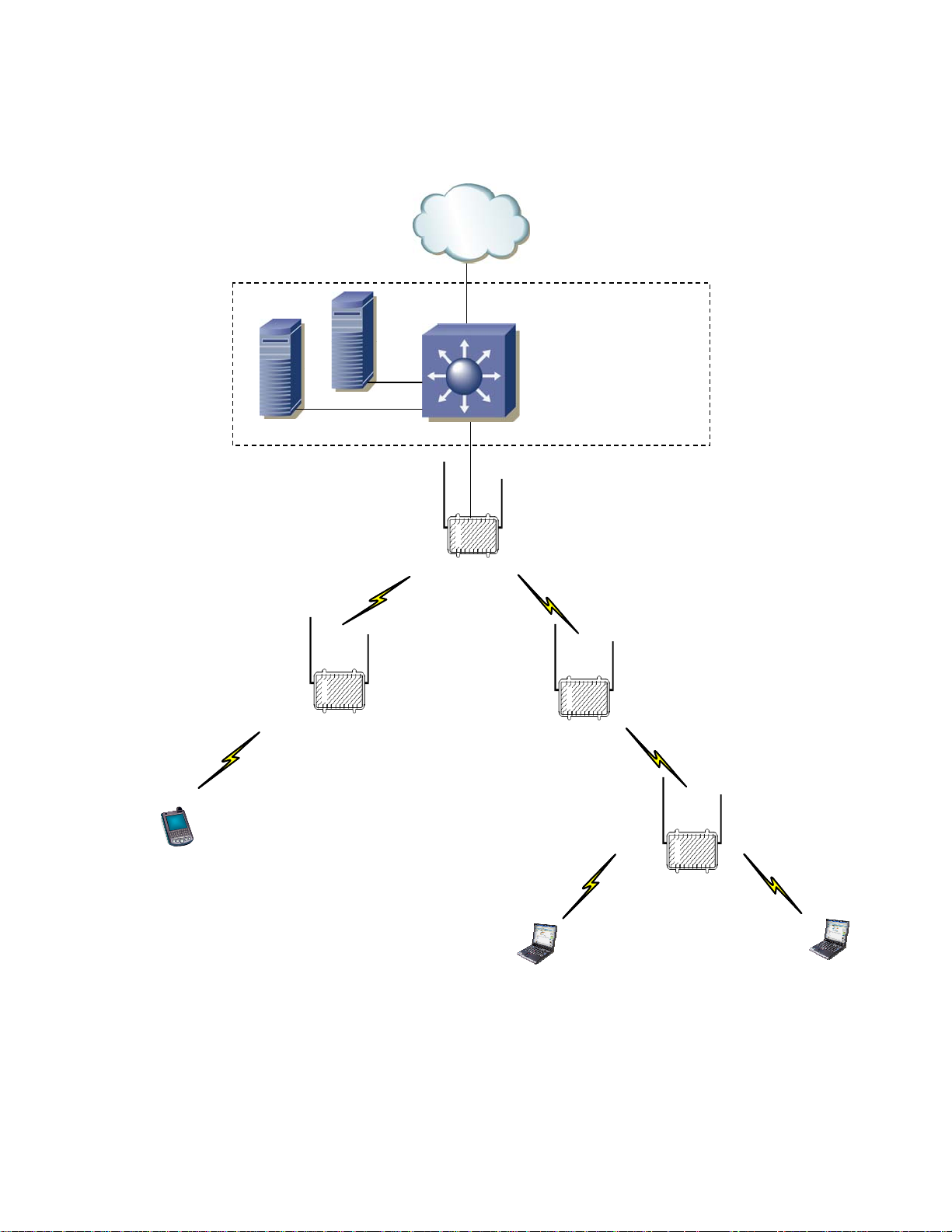
Figure 1-1 2.4 / 5.8 GHz Mesh Network Example
Internet
Internet
RADIUS
Wireless Manager
Wireless Manager
RADIUS
Layer 3 Switch
Layer 3 Switch
Backend Network
Backend Network
2.4 GHz
2.4 GHz
Client
Client
Access
Access
5.8 GHz
5.8 GHz
Mesh
Mesh
MWR
MWR
IAP
IAP
2.4 GHz
2.4 GHz
Client
Client
Access
Access
5.8 GHz
5.8 GHz
Mesh
Mesh
MWR
MWR
5.8 GHz
5.8 GHz
Mesh
Mesh
MWR
MWR
2.4 GHz
2.4 GHz
Client
Client
Access
Access
1-4
Page 19

Chapter 2: Network Setup
Chapter 2: Network Setup
.............................................
.
.
Small System Reference Design
This section details a small system reference design. By understanding the small reference
design one can apply these details to larger networks. A small system reference design is
defined as a network in which the network servers and associated networking hardware are
located at a central location. Wireless or wired bridging may be used to provide connectivity
between the Intelligent Access Points and the switch / router backend.
Chapter
2
Our small system reference design has the following attributes:
• Support for at least 20 IAPs (gateways).
• All IAPs and MWRs will utilize DHCP for network addressing.
• The Network will be configured and managed with the One Point Wireless
Manager™ application residing on a RedHat ES 4 Linux server.
• A Windows 2003 RADIUS server will provide authentication for Secure Mesh.
• The standard small network design does not include server or network hardware
redundancy.
Network Requirements
.............................................
.
Network Servers
There are two network servers used in the small system reference design. The following is
the recommended hardware configuration for these two servers. Variations from the
recommended hardware configuration may result in inadequate system performance.
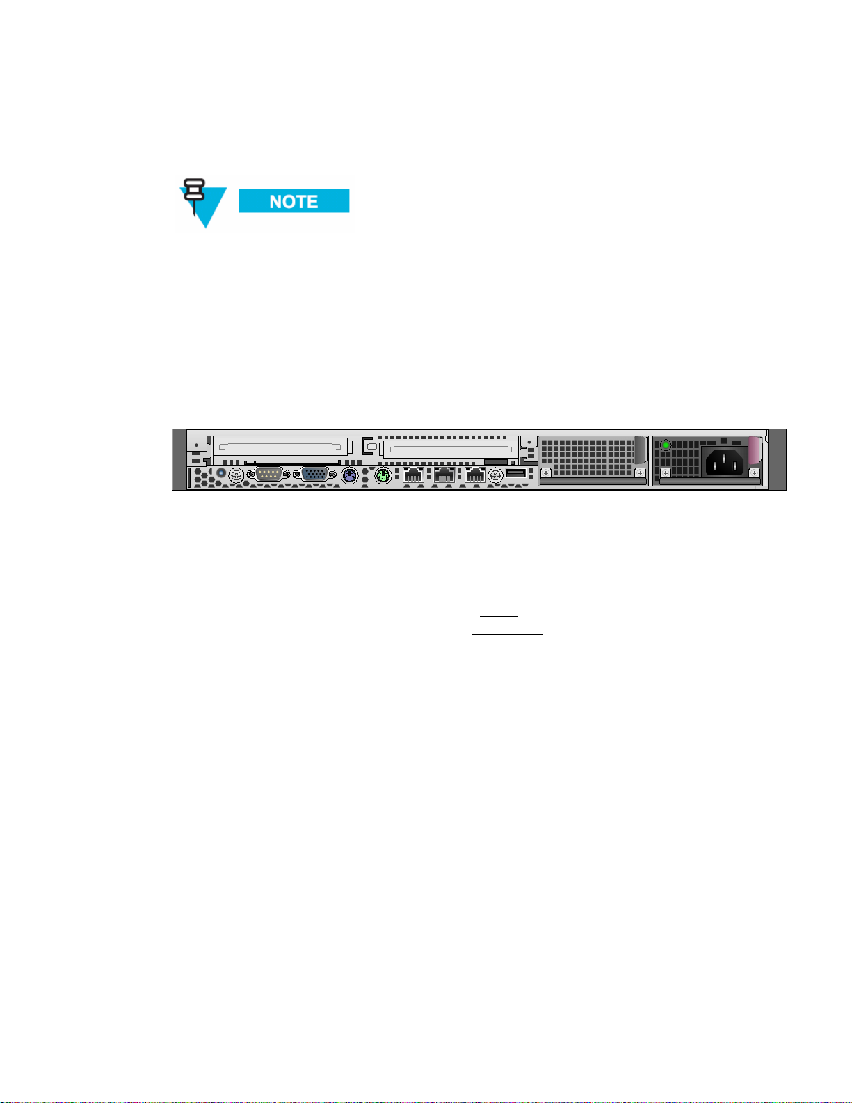
• Enterprise grade server (e.g. Hewlett-Packard ProLiant DL360-G5 3.00GHz
Server)
• Minimum 2 GB of RAM
• (2) 36.4 GB 15K RPM SCSI Hard Disk Drives
2-5
Page 20
Chapter 2: Network Setup
Figure 2-1 HP DL360 G5 server
• Monitor
• Keyboard
• Mouse
These requirements are an approximate estimate intended to allow for
maximum scalability while supporting rapid system response time. As a
minimum, we recommend 2 GB of system memory and redundant hard
drives with a hardware RAID controller of server quality.
One Point Wireless Manager Server
• The One Point Wireless Manager™ server in our reference design server hosts
the One Point Wireless Manager™
configuration and network management. DHCP and DNS will also be configured
on this server and are part of the Linux operating system.
RADIUS - (Optional)
• The Windows 2003 server is optional and is used to support EAP-TTLS Secure
Mesh. Juniper’s Steel Belted Radius application will be configured on the
Windows 2003 server since it supports EAP-TTLS based authentication. The
Windows 2003 Server also provides certificate services which will be used to
generate certificates to support EAP-TTLS. Our RADIUS server could also be
used for certificate based 802.11 client authentication and or store 802.11 client
usernames and passwords. A RADIUS server for Secure Mesh is not required if
PSK Secure Mesh is used instead.
application. This application provides device
2-6
Page 21

Chapter 2: Network Setup
EAP-TTLS Secure Mesh
The MotoMesh 2.1 architecture provides a set of features designed to help network operators
secure the mesh network. These security features can help to protect the mesh network from
intruders and attackers.
It is important to distinguish between the security provided by the MotoMesh architecture
(Secure Mesh) and the security features provided for standard 802.11 clients (e.g. laptops,
mobile Wi-Fi devices, etc.). Mesh Security applies between all of the mesh-enabled devices
that form the mesh network. 802.11 client security (e.g. WEP, WPA-PSK, etc.) is completely
independent of mesh security and is detailed in the WMS Administrator’s Guide.
EAP-TTLS Secure Mesh uses Public Key Infrastructure (PKI) certificates to authenticate the
network infrastructure, a RADIUS server, and a unique user ID and password to uniquely
authenticate each mesh device. EAP mode supports MIC codes and encryption, where
available. EAP mode supports centralized control of per-device authentication credentials by
the RADIUS server, so a compromised device's credentials can be individually revoked
without having to change keys on other devices. Session keys are automatically derived
based on the EAP authentication and rolled periodically at a rate controlled by the RADIUS
server. EAP mode is recommended for medium- or large-sized networks or any network that
requires per-device authentication or centralized control over credentials. EAP mode
requires the "R0 Key Holder" (R0KH) service. The R0 Key Holder service acts as a key
cache, speeding up key generation for devices that already have a valid session key from the
RADIUS server, similar to the R0 Key Holder defined for 802.11r. The R0KH service is
included as part of the Linux environment setup.
Secure Mesh can also be configured to use PSK thus eliminating the RADIUS requirement. Please
see the WMS Administrator’s Guide for detailed steps.
Network Device Ethernet Interconnectivity
This section describes the Ethernet connectivity of the small system reference design. Please
note the specific ports used as the software configuration of the equipment assumes the
stated interconnectivity.
Figure 2-2 Ethernet connectivity between network servers and 3750 L3 Switch
Port 1
Port 2
Ports
3-4
The One Point Wireless Manager server is connected to Port 1 of the L3 Switch.
The RADIUS server is connected to Port 2 of the L3 switch.
Ports 3 and 4 on the L3 switch can be used to connect to other network devices e.g. gateway
router
Ports
5-24
Ports 5-24 will be used for connections to IAPs.
2-7
Page 22

Chapter 2: Network Setup
IP Addressing Plan
Table 2-2 shows the network IP plan for our small system reference design. Four VLANs will
be utilized in our network design (VLAN 1, 24, 31, and 49) each representing a different IP
subnet:
These VLANs are configured in the Cisco Layer 3 switch. A detailed switch configuration is
included in Appendix A.
IP Address Host
• VLAN 1 (10.1.0.0/16 network)
• VLAN 24 (10.24.0.0/16 network)
• VLAN 31 (172.31.0.0/16 network)
• VLAN 49 (10.49.0.0/16 network)
Table 2-1 Core IP Network Plan
172.31.0.2/16
10.1.0.1/16
10.24.0.1/16
10.49.0.1/16
172.31.0.20 One Point Wireless Manager Server
172.31.0.30 to 172.31.255.254 Reserved for other network services servers (VLAN 31)
The table 2-3 lists the address pools that will be configured to support our network. These
address pools are configured on One Point Wireless™ Manager
is available from Motorola that will configure the Linux server with these defaults.
Table 2-2 Wireless VLAN /Subnet IP Network Plan
L3 Switch VLAN 31
L3 Switch VLAN 1
L3 Switch VLAN 24
L3 Switch VLAN 49
DNS server
DHCP server
TFTP Server
server. A Linux setup script
IP Address Host
DHCP Pool 10.1.0.30 – 10.1.255.254
VLAN 1 (Native)
VLAN 1 Address Pool / Untagged devices
DHCP Pool 10.24.0.30 – 10.24.255.254
VLAN 24 (IAP and MWR device addresses)
VLAN 24 Address Pool
2-8
Page 23
Chapter 2: Network Setup
IP Address Host
DHCP Pool 10.49.0.30 – 10.49.255.254
Layer 3 Switch
Overview
The standard small system reference design includes a Cisco 3750 L3 Switch which supports
20 Intelligent Access Points (IAPs). Four switch ports (ports 1-4) are also available for
network servers such as the One Point Wireless Manager™ server and RADIUS. IAPs are
connected to L3 switch (ports 5-24) via one of three methods:
• Direct Ethernet
• Connection via a wireless bridge (Motorola Canopy™ System)
• Connection via a wireline media converter (e.g. Ethernet over Fiber media
converter)
VLAN 49 (802.11 clients)
VLAN 49 Address Pool
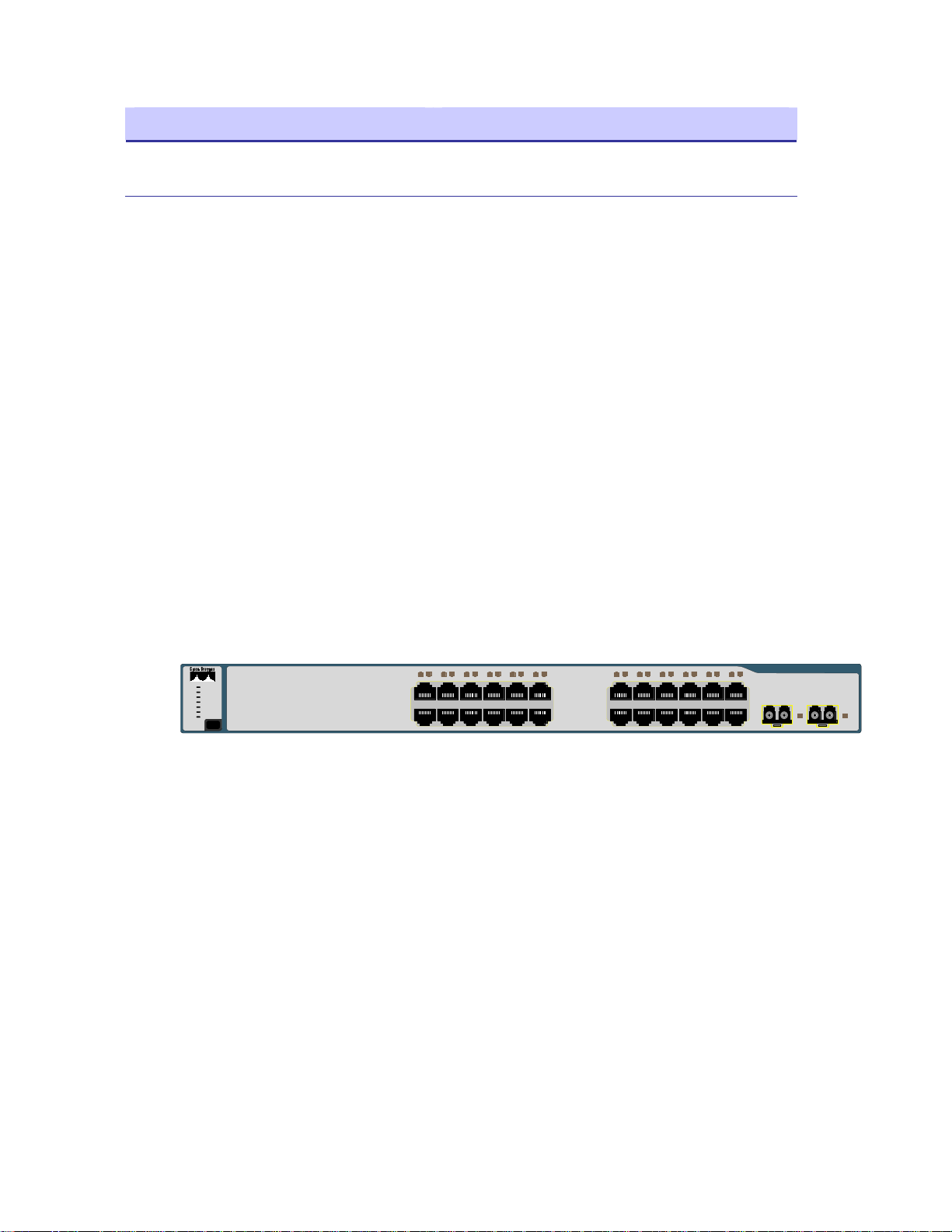
Figure 2-3 Cisco 3750 L3
SYST
RPS
MASTR
STAT
DUPLX
SPEED
STACK
MODE
The Cisco 3750 router provides the following services:
• Routing between the wireless subnets 10.1.0.0 /16, 10.24.0.0/16, 10.49.0.0/16,
and the server network 172.31.0.0/16 (e.g. inter VLAN routing between VLANs
1, 24, 31, and 49).
• DHCP relay from the wireless subnets to the DHCP server running on the One
Point Wireless server 172.31.0.20.
• 802.1Q VLAN tag recognition enabling the support of a trunked set of VLANs
terminating on a single physical interface
IP Directed Broadcasts
1234567891011
1X
2X
Catalyst 3750
12
11X
12X
1314151617181920212223
13X
14X
24
23X
24X
SERIES
1 2
By default, the 3750 Switch drops IP directed broadcasts; thus preventing them from being
forwarded. The One Point Wireless Manager™ application utilizes SNMP broadcasts for
automatic network discovery. We have enabled IP directed broadcasts in the 3750 L3 switch
2-9
Page 24

Chapter 2: Network Setup
in order to prevent the switch from dropping these discovery packets. See Appendix A for
detailed steps on how to configure the IP directed broadcast feature on the 3750 L3 switch.
VLAN Setup
The L3 network switch provides the ability to segment management and user traffic using a
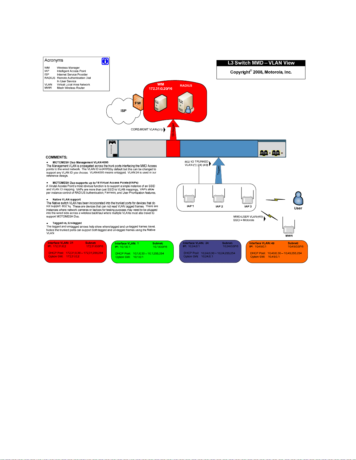
combination of VLAN tagging and firewall access control rules, see Figure 2-4. In the small
system reference design the L3 switch has been configured with the following 4 VLANs each
representing a different IP subnet per our IP plan:
• VLAN 31 is configured on Ports 1-4. Ports 1-4 are access ports only (non-tagged)
• VLAN 1 is the native VLAN of the L3 switch by default. Ports 5-24 have been
and are used by network servers such as the One Point Wireless Manager™
(172.31.0.20/16) and RADIUS. VLAN 31 has the address of 172.31.0.2/16. Note
how the second octet of the IP address (31) is aligned with the VLAN number. This
has been done to simplify the IP design.
configured as trunked ports and have VLAN 1 in their allowed VLAN list. VLAN 1 has
the IP address of 10.1.0.1/24. It has been configured to support non VLAN capable
devices such as cameras and other IP devices. This VLAN is also configured with an
IP helper address of 172.31.0.20 (The address of the Wireless One Point Manager™
server) to service any DHCP requests received on this VLAN.
server
• VLAN 24 is also included in the allowed VLAN list on ports 5-24. VLAN 24 has the
address of 10.24.0.1/16. VLAN 24 has been configured to be used as a
management VLAN. The management VLAN is used to communicate management
data from the One Point Wireless Manager™
VLAN is also configured with an IP helper address of 172.31.0.20 (The address of
the Wireless One Point Manager™ server) to service any DHCP requests received
on this VLAN.
• VLAN 49 is also included in the allowed VLAN list on ports 5-24. VLAN 49 has the
address of 10.49.0.1/16. VLAN 49 has been configured to be used by wireless
clients. As mentioned previously a MOTOMESH Duo device supports up to 15
Virtual Access Points (VAPs) per radio. Each VAP can be configured to have a
unique VLAN. Thus, in this example, VLAN 49 has been created to support a client
VAP. Note that this VLAN tag will be stripped off prior to data being sent to client
devices (VLAN tag stripping is on by default on client VAPs). Traffic that originates
from a client would be tagged with VLAN 49. This VLAN is also configured with an IP
helper address of 172.31.0.20 (The address of the Wireless One Point Manager™
server) to service any DHCP requests received on this VLAN.
application to IAPs and MWRs. This
2-10
Page 25
Chapter 2: Network Setup
Figure 2-4 L3 Switch for MOTOMESH Duo 2.1 - VLAN View
Catalyst 3750
1234567891011
SYST
RPS
MASTR
STAT
DUPLX
SPEED
STACK
MODE
1X
2X
12
11X
12X
1314151617181920212223
13X
14X
24
23X
24X
SERIES
1 2
VLAN Examples
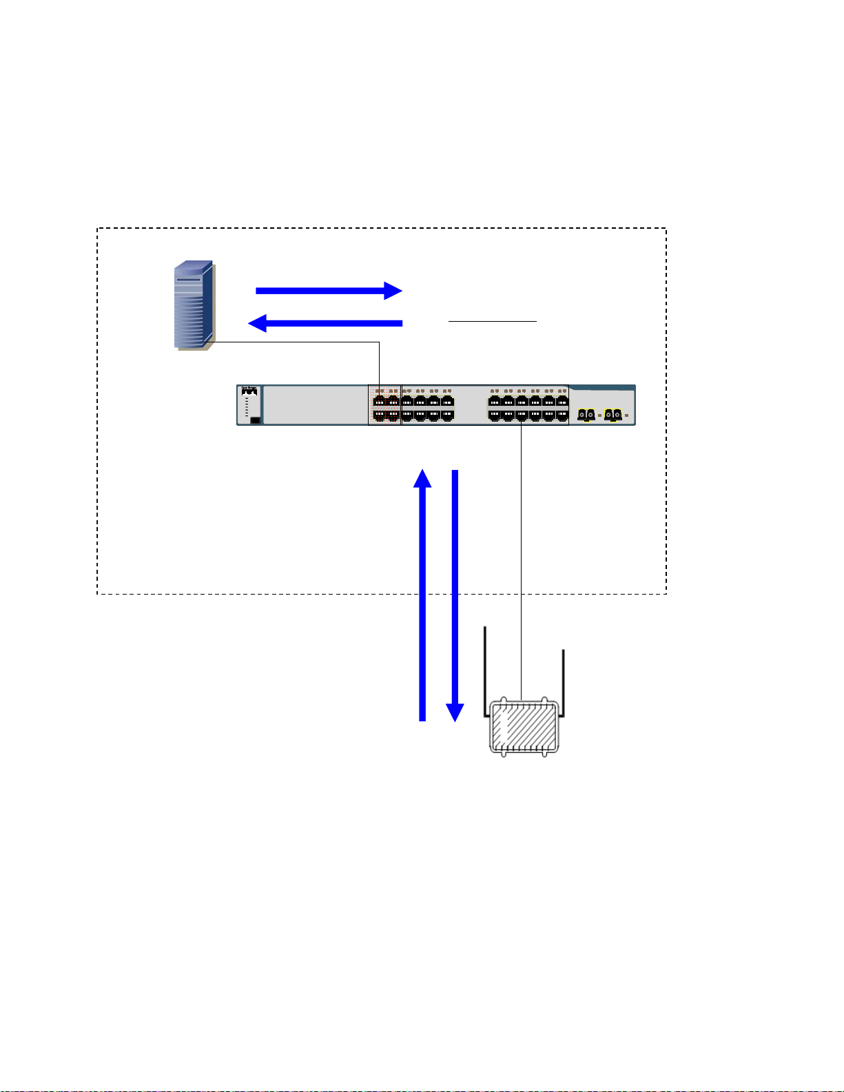
In order to better understand how VLANs are used in our small system reference design let’s examine
how traffic traverses these VLANs. In the example below the One Point Wireless Manager
connected to port 1 and our IAP is connected to port 18. Management VLAN 24 has been configured on
our IAP as well as DHCP. When the IAP is powered on it obtains an IP address in the follow steps:
1. The IAP requests an IP address via DHCP. This request is sent over VLAN 24.
2. The 3750 switch receives the DHCP request on Port 18 which is configured to accept packets on
VLAN 24. VLAN 24 is configured on the L3 switch to forward DHCP requests to the One Point
Wireless Manager
Point Wireless Manager server
™ server via the configured IP helper address 172.31.0.20. Since the One
™ is connected to port 1, and ports 1-4 are a part of untagged
VLAN 31, the tag is removed and the DHCP request is forwarded out port 1 to the One Point
Wireless Manager
™ server.
™ server is
2-11
Page 26
Chapter 2: Network Setup
3. The DHCP server observes that the request originates from the 10.24.0.0/16 network. It answers
this request with a 10.24.X.X/16 IP address. Please recall that this DHCP pool has been
configured on the DHCP server running on the One Point Wireless Manager
™ server.
4. The 3750 switch receives this reply and forwards it out back on VLAN 24 to the IAP.
Figure 2-5 VLAN Example 1
Wireless Manager
Wireless Manager
172.31.0.20
172.31.0.20
3
3
Layer 3 Switch
Layer 3 Switch
2
2
VLAN 24 10.24.0.1
VLAN 24 10.24.0.1
IP helper address 172.31.0.20
IP helper address 172.31.0.20
Catalyst 3750
SERIES
Catalyst 3750
12
1234567891011
1234567891011
1X
SYST
SYST
RPS
RPS
MASTR
MASTR
STAT
STAT
DUPLX
DUPLX
SPEED
SPEED
STACK
STACK
MODE
MODE
1X
2X
2X
12
11X
11X
12X
12X
1314151617181920212223
1314151617181920212223
13X
13X
14X
14X
24
24
23X
23X
24X
24X
SERIES
1 2
1 2
4
4
In our next example
1
1
IAP
IAP
Management
Management
VLAN 24
VLAN 24
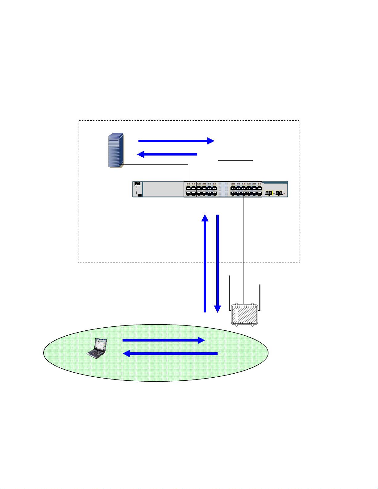
In the next example an 802.11 client has associated to a virtual access point on our IAP. The DHCP
exchange is as follows:
1. The client sends a DHCP request.
2. The IAP tags this request with VLAN 49 and forwards it to the 3750 switch.
3. The 3750 switch receives the DHCP request on Port 18 which is also configured to accept
packets on VLAN 49. VLAN 49 is configured on the switch to forward DHCP requests to the One
Point Wireless Manager
One Point Wireless Manager
untagged VLAN 31, the tag is removed and the DHCP request is forwarded out port 1 to the One
Point Wireless Manager
™ server via the configured IP helper address 172.31.0.20. Since the
™ server is connected to port 1, and ports 1-4 are a part of
™ server.
2-12
Page 27
Chapter 2: Network Setup
4. The DHCP server observes that the request originates from the 10.49.0.0/16 network. It answers
the request with a 10.49.X.X/16 IP address. Please recall that this DHCP pool has been
configured on the DHCP server running on the One Point Wireless Manager
™ server.
5. The 3750 switch receives this reply and forwards it out back on VLAN 49 to the IAP.
6. The IAP strips off the VLAN tagged and sends the reply to the client.
Figure 2-6 VLAN Example 2
4
Wireless Manager
Wireless Manager
172.31.0.20
172.31.0.20
4
3
3
Layer 3 Switch
Layer 3 Switch
VLAN 49 10.49.0.1
VLAN 49 10.49.0.1
IP helper address 172.31.0.20
IP helper address 172.31.0.20
12
1234567891011
1234567891011
1X
SYST
SYST
RPS
RPS
MASTR
MASTR
STAT
STAT
DUPLX
DUPLX
SPEED
SPEED
STACK
STACK
MODE
MODE
1X
2X
2X
12
11X
11X
12X
12X
1314151617181920212223
1314151617181920212223
13X
13X
14X
14X
Catalyst 3750
SERIES
Catalyst 3750
24
24
SERIES
23X
23X
1 2
1 2
24X
24X
5
5
2
802.11
802.11
Client
Client
1
1
Virtual Access Point configured
Virtual Access Point configured
2.4 GHz
2.4 GHz
To use VLAN 49
To use VLAN 49
2
IAP
IAP
6
6
MOTOMESH Duo Device Defaults
MOTOMESH Duo devices come from the factory with the following default settings:
2-13
Page 28

Chapter 2: Network Setup
• All devices are IAPs
• DHCP enabled
• VLAN support enabled
• Management configured as VLAN 4095. A management VLAN of 4095 means
• Backhaul detection on – If a MOTOMESH Duo device does not detect a wired
untagged. Thus when a MOTOMESH device requests an IP address for the first time
the DHCP request will come in as untagged and will be serviced by VLAN 1. Thus
the device will receive a 10.1.X.X/16 address (e.g. if the small system reference
design defaults are used). The management VLAN can then be changed to another
VLAN e.g. VLAN 24 used in the reference design. (The management VLAN would
be changed to VLAN 24 and the device rebooted. The device would then get a
10.24.x.x address).
backhaul connection it will convert itself from an IAP to an MWR. The Backhaul
detection feature is comprised of active ping and link layer detection. By default, the
IAP will ping the gateway address received in the DHCP reply. If an IAP is statically
configured then an IP address will need to be entered into the backhaul detection
settings (in the One Point Wireless Manager™ application or via the webpage
interface) for the Backhaul Detection feature to operate correctly. Improper
configuration will lead to the IAPs configuring themselves to operate in degraded
mode which is an IAP acting as an MWR.
If an IAP is addressed via DHCP, the gateway address received in the DHCP reply
will be used as the logical address the IAP will ping for logical backhaul detection.
If the IAP is statically configured a valid “pingable” IP address must be configured
in the backhaul detection settings or the IAP will enter degraded status and
operate as an MWR.
Preparing the One Point Wireless Manager Server
This section describes the procedure for the installation of Red Hat Enterprise Linux ES
Version 4, Update 5 (retail box) in a configuration suitable for use with the One Point Wireless
Manager™ application in our small system reference design. While other versions of Red Hat
Linux or another Linux distribution may be suitable to use, discussion of support for other
versions is outside the scope of this section.
2-14
Page 29

Chapter 2: Network Setup
If you choose another version of Red Hat Linux or an alternate distribution, the
content of this manual should only be used as general guidelines for the
installation process.
Minimum Software Requirements
The following table lists the software versions required to support the One Point Wireless
Manager™ application on the Linux platform.
Table 2-3 Software Requirements for One Point Wireless Manager
Device Software Revision
Red Hat Enterprise Linux ES 4.0 Update 5
Java Runtime Environment 1.6 or higher (included with Wireless Manager application)
MySQL 5.0.40 (included with Wireless Manager application)
Red Hat Linux Installation
Starting the Red Hat Enterprise Linux ES Installation
The MOTOMESH 2.0 One Point Wireless Manager™ application is designed to run on a 32bit version of the Red Hat operating system. If supported by the BIOS settings, booting with
the Red Hat Enterprise Linux ES CD inserted will initialize the installer. If this is not the case,
you may have to configure your server BIOS to boot from removable media first. Refer to
your server documentation for information on changing BIOS settings. The following section
describes how to install RedHat Linux using our reference design defaults.
You must install the 32-bit version of the Red Hat OS.
Installation of Red Hat Enterprise Linux ES
Complete Procedure 2-1 to install the Red Hat Linux ES software.
Procedure 2-1 Red Hat Enterprise Linux ES Installation on HP DL360 G5 Server
Insert the first Red Hat Enterprise Linux ES install CD and reboot the server. The system
1
should boot up to the following screen:
[F1-Main] [F2-Options] [F3-General] [F4-Kernel] [F5-Rescue ]
boot:
2-15
Page 30

Chapter 2: Network Setup
A Press the Enter key to begin the installation in graphical mode. If no key is pressed, the
2
system will auto launch in 60 seconds.
The following prompt will appear:
3
To begin testing the CD media before installation press OK. Choose Skip to skip the media test
and start the installation.
Choose Skip.
The Welcome to Red Hat Enterprise Linux screen will be displayed. Click on the Next
4
button.
Select the appropriate Language Selection setting and click on the Next button.
5
Select the appropriate Keyboard Configuration setting and click on the Next button.
6
If you are installing from other than the retail boxed set, you may be prompted to
perform a media check. While this step is time consuming, it ensures a successful
installation.
7
8
9
10
11
Select Automatically Partition and click on the Next button.
Select Remove all partitions on this system.
This setting will erase any and all existing operating systems and
data.
Use the default drive that is highlighted under Select the drive(s) to use for this installation.
Make sure that Review is checked at the bottom of the page. This allows you to view and
change the automatic partitioning results. Click on the Next button. Click Yes in the Warning
dialog box that appears.
It is recommended that the user create a separate /var partition for storing log files and
databases. This ensures that the files to be created will not fill up all available space on the
system partitions and will also help prevent fragmentation in the file system.
Click on the New button. A dialog box will pop up to create a new partition. Enter or verify the
following parameters:
Mount Point: /var
File System Type: use the default setting
Allowable Drives: use the default setting
Size (MB): 10000
Additional Options: Fixed Size
12
13
Click on the OK button. Check the partitions display to ensure that the new /var partition was
created. Click on the Next button.
The default Boot Loader Configuration will already be correct. Click on the Next button.
2-16
Page 31

Chapter 2: Network Setup
14
15
16
When the Network Configuration screen is displayed, click on the Edit button. Uncheck
Configure using DHCP. Input the following;
IP Address: 172.31.0.20
Netmask: 255.255.0.0
Click on the OK button.
Input the remaining network data.
Host Name: WMS
Gateway: 172.31.0.2
Primary DNS: 172.31.0.20
Click on the Next button.
It is suggested that you select the No Firewall option when the Firewall Configuration screen
is displayed. Click on the Next button.
Selecting another option may impact the function of network services, including
WMS.
On the same page, make sure SE Linux is set to disable.
17
18
19
20
21
22
When the Additional Language Support screen is displayed, select any additional language
options required. Click on the Next button.
When the Time Zone Selection screen is displayed, select the appropriate settings for your
geographic location. Click on the Next button.
When the Set Root Password screen is displayed, input your root password. The reference
design default is g0ld11. Input and confirm the password. Click on the Next button.
At the Package Installation Defaults screen, select Customize the set of packages to be
installed. Click on the Next button.
You may now choose the packages to be installed. In addition to the defaults, you must
choose the following to satisfy prerequisites for the One Point Wireless Manager™ application:
- KDE Desktop Environment (To Make KDE your default Desktop Environment unselect
"GNOME Desktop Environment" package, or it will be automatically selected)
- Editors
- Graphical interface – Only Firefox
- DNS Name Server
- Network Servers
You may choose any desired packages as well as a preferred window manager at this time.
Click on the Next button when you are satisfied with the package selection.
The installer is now ready to copy files to the server. Click on the Next button to continue. The
installer will format and copy files to the hard drive. This process will take several minutes. You
will be prompted for additional discs.
23
When the Congratulations screen is displayed, the Red Hat Enterprise Linux ES installation is
complete. Remove any install media and click on the Reboot button.
2-17
Page 32

Chapter 2: Network Setup
24
25
26
24
25
26
27
The server should reboot and bring up the Welcome screen. Click on the Next button to
continue.
Click on the Yes button to accept the License Agreement and then click on the Next button to
continue.
Verify the correct date and time for your server and then click the Next button to continue.
When the Monitor Configuration screen is displayed, your monitor should be detected and
selected by the installer. If your monitor type is not listed, choose a suitable setting from the
Generic CRT Display category.
Choose the desired color depth and resolution. A recommended minimum is at least 16-bit
color and a 1024 X 768 resolution. Click on the Next button.
When the Customize Graphics Configuration screen is displayed, choose the desired color
depth and resolution. A recommended minimum is at least 16-bit color and a 1024x768
resolution. Click on the Next button.
At the Red Hat Network screen, make your selection and click on the Next button to continue.
You can enter the Remote Support User Account at this time.
It is highly recommended to add the meshmgr user for remote support
capabilities. Use the information below to create this account.
Username: meshmgr
Full Name: Remote Support
Password: g0ld10
Confirm Password: g0ld10
Click on the Next button to continue.
28
At the Additional CDs screen, click on the Next button if you have no other CDs to install at
this time.
29
The Finish Setup screen will be displayed. Click on the Next button to continue.
For optimal screen viewing configure the video adapter display resolution to at
least 1024 X 768.
To prevent the smartd alarm from occurring during the server boot process you
can execute "chkconfig --level 345 smartd off" at a command prompt.
2-18
Page 33

Chapter 2: Network Setup
Running the DHCP and DNS Install Script
Prerequisites
All prerequisite conditions must be observed to ensure proper installation of the additional
components required to support the One Point Wireless Manager™ application on a Linux
platform.
1. You must be logged on as the root user under a KDE Session. At the Welcome to
2. Enter the Username: root and press Enter.
3. Enter the Password: g0ld11 and press Enter.
The following steps are required to install the Linux environment setup
/opt/motoMeshDuo_setup as a working directory. This script will set up DHCP and DNS as
specified by the small system reference design. It will also install the r0kd daemon which is
required if EAP-TTLS Secure Mesh is going to be used.
WMS screen, select KDE under the >Session menu at the bottom of the screen.
Click the OK button to continue.
Procedure 2-2 DHCP and DNS Install Script
Insert the CD containing the Linux environment setup archive into the CDROM drive.
1
Right-click on the desktop and select Open Terminal to launch a new terminal shell.
2
Execute the following commands:
mkdir /opt/MotoMeshDuo_setup
cp -f /media/cdrom/Tools/motomesh_duo_linux_setup.tar.gz /opt/MotoMeshDuo _setup
cd /opt/MotoMeshDuo _setup
zcat motomesh_duo_linux_setup.tar.gz | tar xf bash ./install
Observe the following prompt:
3
Do you want to setup Networking? This will overwrite any existing network settings. [yes or
no]
Enter yes.
Observe the following prompt:
4
Do you want to use this machine as a DHCP server?
Enter yes.
Observe the following prompt:
5
Do you want to start the DHCPD service?
Enter yes.
2-19
Page 34

Chapter 2: Network Setup
Observe the following prompt:
6
Do you want to use this machine as a DNS server?
Enter yes.
Observe the following prompt:
7
Do you want to continue with the installation of bind and associated files?
Enter yes.
8
9
10
11
12
If this prompt is not displayed, continue to Step 8.
Observe the following prompt:
The default DNS domain suffix to be used is meshnetworks.net
Do you want to change this? [yes or no]
Enter no.
Observe the following prompt:
Do you want to start the DNS server?
Enter yes.
Observe the following prompt:
Do you want to configure this machine to run a TFTP server? [yes or no]
Enter yes.
Observe the following prompt:
Do you want to configure this machine to run a Time server? [yes or no].
Enter No.
Observe the following prompt:
Do you want to install the r0k daemon on this machine?
Enter Yes.
When you enter yes, you will be asked for the location of the r0k config file. The r0k
daemon is required when using EAP-TTLS Secure Mesh.
13
Observe the following prompt:
Starting installer for r0k daemon
./r0kd_install.sh
Enter binary installation directory [/opt/r0kd]:
Enter /opt/MotoMeshDuo _setup/.
It will show the install locations, and then prompt for the install start.
2-20
Page 35

Chapter 2: Network Setup
14
15
16
Observe the following prompt:
Binary install directory: /opt/MotoMeshDuo _setup/
Configuration install directory: /etc
Ready to install. [Y/n]:
Enter Y to start the installation of the r0k daemon.
You may see the following prompt during the r0k daemon installation:
`/opt/MotoMeshDuo _setup/r0kd' -> `/opt/MotoMeshDuo _setup/r0kd'
`/opt/MotoMeshDuo _setup/r0k.conf' -> `/etc/r0k.conf'
r0kd will now be set to startup in runlevels 3-5.
r0kd doesn't appear to be running, start it? [Y/n]:
If you see this, enter N. The daemon will be started later when EAP-TTLS Secure Mesh is
configured.
Verify that the hardware IP address assignments are correct. It may take several minutes
for the IP interfaces to come up after the install script completes. At the command prompt
type:
[root@ WMS root]# ip addr
Several lines of text similar to the following will be displayed:
eth0: <BROADCAST,MULTICAST,UP> mtu 1500 qdisc pfifo_fast qlen 1000
link/ether 00:0c:76:4e:5b:4e brd ff:ff:ff:ff:ff:ff
inet 172.31.0.20/16 brd 172.31.255.255 scope global eth0
17
18
19
Verify that an entry for WMS has been added to the /etc/hosts file. Confirm that the
remaining entries are correct. At the prompt, type the following:
[root@ WMS root]# cat /etc/hosts
Several lines of text similar to the following will be displayed:
127.0.0.1 localhost
172.31.0.20 WMS WMS.meshnetworks.net
Try to ping the hostname WMS by typing the following at the terminal window prompt:
[root@WMS root]# ping WMS
Several lines of text similar to the following will be displayed:
PING WMS (172.31.0.20) 56(84) bytes of data.
64 bytes from WMS (172.31.0.20): icmp_seq=0 ttl=0 time=0.047 ms
64 bytes from WMS (172.31.0.20): icmp_seq=2 ttl=0 time=0.040 ms
Verify that you get a reply from WMS. Press CTRL-C to return to the terminal window.
Keep the window open for the next step.
2-21
Page 36

Chapter 2: Network Setup
20
If the bind and DHCP services were started, it is important to verify that a second machine
is able to receive an IP address. Configure a second machine to receive an IP address via
DHCP from the MiSC.
Installing the One Point Wireless Manager™ Application
Now that the Linux operating system and DHCP/DNS scripts have been installed on our
server, we can now install the One Point Wireless Manager™ Application.
For information about how to install this application, please refer to the
Installation Guide found on the provided product CDs. If you require information about
upgrading an existing MOTOMESH Duo system, please refer to the MOTOMESH Duo 2.1
Field Upgrade Procedures documentation, also found on the provided product CDs.
WMS Setup and
Preparing the Windows 2003 Server and Juniper RADIUS
Installing Windows 2003 Server
As discussed in the section detailing the small system reference design a Windows 2003
server will be configured with RADIUS to support EAP-TTLS Secure Mesh. In this example
we will be installing Windows 2003 Server on an HP DL360 G5 server.
The following installation procedure requires valid Windows 2003 R2 Second Edition media
and license and the HP Smart Start CD from the HP ProLiant Essentials Foundation Pack.
Procedure 2-3 Windows 2003 Server Installation
1
2
3
4
5
Insert the Windows 2003 Server Standard Edition CD in the CD drive.
Reboot the PC and the system should boot from the CD. If the systems does not boot from the
CD, use system setup to alter the BIOS device boot order to boot from CD before the hard
drive.
From the Windows setup screen, press Enter to start the installation.
If an existing installation is detected, the installer will offer the opportunity to repair it. Follow the
on-screen instructions to continue with a new installation..
At the next screen, press F8 to agree to the software license.
The next screen lists the current disk setup.
Use D to delete any existing partitions, follow the on-screen instructions to confirm the
deletions.
The screen should show the entire disk as unpartitioned space. Press C to create a partition.
The default is to use the entire disk. Press Enter to accept this.
6
At the disk setup screen, select the new partition and press Enter to start the installation
process. Use Enter again to format the disk with an NTFS files system.
2-22
Page 37

Chapter 2: Network Setup
7
8
9
10
11
12
13
14
15
16
Once formatting is complete, the system will copy the installation files to the drive. Upon
completion, the system will reboot. On reboot, do not press a key to boot from CD; just allow
the system to boot into the Windows 2003 Server Setup to continue with the installation.
After a period of time, the Regional and Language Options dialog will appear. The default
selection of English (United States) is correct. Select Next.
Enter a Name and Organization, then select Next.
Depending on the media used for install, the Product Identification screen may appear. If it
does, enter the 25-digit key and select Next.
Select per Server for licensing mode unless there is a specific requirement for different
licensing according to the deployment. Select Next.
Enter a Computer Name: radius, and enter an administrator password G0ld11 (Windows
2003 Server requires you to use a capital letter in the administrator password).
Select Next and then select Yes at the dialog box to accept the password as is.
Set the correct Date and Time, and Time Zone. Select Next; the installation will continue.
After a period of time this system will reboot. Again, avoid pressing a key to boot from the CD.
The system will boot to the login prompt. Login as administrator using the password previously
defined.
Adjust any necessary settings, such as display size, etc, as needed.
Open Control Panel | System and select the Computer Name tab. Next select the Change
option and then the More button. Set the primary DNS suffix to meshnetworks.net. Upon
confirmation, the system will request a re-start. Select Yes.
17
When the reboot is done, the base Windows 2003 Server Installation is complete.
Driver Installation for HP DL360 G5 Server
Windows 2003 server does not recognize the HP GL360 G5’s Ethernet adapter by default
and drivers must be loaded. The server comes with a driver CD which can also be obtained
online at HP’s website.
Procedure 2-4 Ethernet Driver Installation for the HP DL360 G5 Server
1
2
3
4
5
6
7
Insert the HP Smart Start CD.
The License and Smart Start GUI will display. Accept the license.
Select Start menu.
Right mouse button, click on My Computer and select Properties popup menu option.
Select Hardware tab.
Select Device Manager button.
Select the Other devices group.
8
Right-click on one of the two Ethernet Controllers and select Update Driver.
2-23
Page 38

Chapter 2: Network Setup
9
10
11
12
13
14
15
Select the Install software automatically radio button from the Hardware Update Wizard
and click Next
Be sure the hardware update wizard locates the HP NC7782 Gigabit Server driver on the HP
Smart Start CD follow the wizard prompts to install the driver.
After the first driver is installed, repeat steps 8-10 to continue configuring the second Ethernet
Controller.
The end result will be two configured network adapters. However,
AFTER the Ethernet Controller drivers are configured, the next step is to
configure a single LAN network connection (as described in the
following steps).
Select Start | Control Panel | Network Connection | Local Area Connection
Select Properties button from Local Area Connection Status window
Highlight the Internet Protocol (TCP/IP) line and select Properties.
In the Internet Protocol (TCP/IP) Properties panel:
1. Select the Use the following address radio button
2. Enter an IP address of 172.31.0.21.
3. Enter a Subnet mask of 255.255.0.0
4. Enter a Default gateway of 172.31.0.2
5. Select the Use the following DNS server addresses radio button
6. Enter a Preferred DNS server address of 172.31.0.20
7. Click the OK button
Installing Windows 2003 Support Tools
The following procedure provides installation instructions for Windows 2003 Support Tools.
Procedure 2-5 Windows 2003 Support Tools Installation
16
17
18
19
20
21
Re-insert the Windows 2003 Server Installation media.
Be sure NOT to trigger a re-install or update of Windows 2003.
Select the Perform Additional Tasks option.
Select Browse this CD.
Enter the \Support\Tools\ folder.
Double-click on SUPTOOLS.MSI and follow all on-screen instructions.
Microsoft Certificate Authority Services
.............................................
2-24
Page 39

Chapter 2: Network Setup
.
.
The following section details how to set up Windows 2003 Server to provide certificate
services. Digital certificates are required in order to exchange and/or validate security
credentials in support of Secure Mesh.
Procedure 2-6 describes how to install certificate services in a Microsoft Windows 2003
Server.
Procedure 2-6 Installing Certificate Services
Add the Certificate Services and the IIS windows component.
1
Assuming that the permanent hostname and domain registration of the server selected to
provide certificate services has already been set, perform the following steps to begin
installation:
• Open Settings / Control Panel and select Add/Remove Programs.
• Open the Add/Remove Windows Components dialog window and add the
Certificate Services and Application Server (IIS) components. Read the note about
not being able to change hostname or domain registration and click Yes to confirm.
Create a stand-alone root CA.
2
• Click Next until the “CA Type” dialog box appears.
• Choose Stand-alone root CA and click on Next.
Enter CA information.
3
Enter all of the requested identifying information for the CA. It is highly recommended, but not
required, to complete all fields. The default five year certificate validity period specified at the
bottom of the dialog is sufficient for most deployments. In our reference design we chose a
common name of radius.
Complete the installation.
4
The default settings are valid on all remaining dialog boxes, simply press Next to continue until
you are prompted for the Service Pack 1 CD-ROM. Insert the Disk 1 of the Windows 2003 R2
installation media into the CD-ROM and click OK.
2-25
Page 40

Chapter 2: Network Setup
Verify correct installation of CA services.
5
Once installation is complete:
• Verify correct installation by opening the Certificates (Local Computer). Click Start |
Run | and type MMC.exe. Press enter.
• Browse to the certificate store by selecting: Console / Add/Remove Snap-in / Add… /
Certificates / Computer Account.
Result: The select PC dialog appears.
• Select Local Computer.
• Ensure that the new CA certificate is stored in the Trusted Root Certification Authorities
/ Certificates folder. You should see a trusted root certificate called radius.
Click on the personal folder and click on certificates. Delete the auto generated
certificate called radius. We will re-create this later.
Verify that the certificate services web interface is functional.
6
Using another computer on the network, connect to the certificate server's certificate services
interface at URL: http://172.31.0.21/certsrv.
Configuring Automatic Certificate Issuing
Procedure 2-7 describes how to configure whether or not an administrator needs to approve
certificate requests (manual or automatic issuing).
Procedure 2-7 Configuring Automatic Certificate Issuing
Open the Certification Authority item by selecting Control Panel / Administrative Tools.
1
Right click on the name of your local root CA server in the tree view and select Properties.
2
Open the Policy Module tab and click the Properties… button.
3
Select the radio button labeled Follow the settings in the certificate template, if applicable.
4
Otherwise, automatically issue the certificate from the Reques t Handling tab.
Restart the Certificate Services to have the changes take effect.
5
• Selecting Control Panel / Administrative Tools / Services.
• Select and restart the Certificate Services service.
Requesting a Server Certificate
The procedure to request a certificate for a network server creates a digital certificate for the
RADIUS server to use for EAP-TTLS authentication.
A server certificate signed by our new CA as well as a copy of the trusted root certificate must
be installed on the RADIUS server. Procedure 5-6 describes how to generate a server
certificate. You must have administrator access on this computer to install the certificates in
the local computer store (required).
2-26
Page 41

Chapter 2: Network Setup
Procedure 2-8 describes how to install certificates on the authentication server.
Procedure 2-8 Installing Certificates on the Authentication Server
Connect to the certificate server web site.
1
From the RADIUS server computer, connect to the certificate server certificate services interface:
e.g., http://172.31.0.21/certsrv
If prompted, enter the authentication information of a domain user. You may also need to add this
web site to your list of trusted sites if you are using a recent version of Internet Explorer.
Select Request a certificate from the task selection page.
3
Select Advanced certificate request.
4
Select Create and submit a certificate request to this CA.
5
Submit the certificate request. This involves filling in any identifying information requested and
6
any other options you require.
• Fill in all of the Identifying Information fields. The Name on the certificate should be that
of this server since it will be the server running radius. Enter the name radius in the
name field. Fill in the rest of the field e.g. email, company, etc.
• In the dropdown box change the Intended Purpose field to Server Authentication
Certificate.
• Check the Mark keys as exportable and Store certificate in the local computer
certificate store boxes.
• Click Submit.
Result: A confirmation dialog appears informing the user that the website is requesting a
certificate on their behalf and if they truly wish to request this certificate now.
• Click Yes.
Since we set up our certificate service to automatically issue certificates you will be immediately
8
be presented with a certificate to install. Click on the certificate to install.
Verify the certificate installation.
9
• Once installation is complete, verify correct installation by:
• Open the Certificates (Local Computer) MMC plugin: Start / Run / MMC.exe.
• Browse to the certificate store by selecting: Console / Add/Remove Snap-in / Add… /
Certificates / Computer Account.
Result: The select PC dialog appears.
• Select Local Computer.
• Ensure that the new server certificate is stored in the Personal / Certificates folder.
If you do not find the CA certificate in the computer account / Local Computer certificate store as
indicated, it may have been copied to the my user account / Current User certificate store instead.
2-27
Page 42

Chapter 2: Network Setup
Authentication Server Configuration
.............................................
.
.
Juniper Steel-Belted RADIUS
This section describes how to configure Juniper Steel Belted Radius server in support of
EAP-TTLS Secure Mesh. Any Radius server package can be used as long as it supports
EAP-TTLS authentication.
The pre-requisites for the procedure in this section are:
• Windows 2003 server installation complete.
• Installation of our Certificate Authority (CA).
• Creation of a server certificate.
• Steel Belted Radius Enterprise Edition (available from Juniper.net). Download /
purchase SBR installer and proceed to install the program by double clicking the
installer. We download an evaluation copy of this example. Contact Juniper
Networks to purchase a licensed copy.
After the installation SBR is complete we need to add our trusted root and server certificate to our Steel
Belted Radius server.
Exporting Certificates
Procedure 2-9 describes how to export existing certificates and install them for use with
Steel-Belted RADIUS.
Procedure 2-9 Exporting Certificates
With the installation of our certificate authority in the previous section and the creation of a server
certificate we need to add these to Steel Belted Radius.
Find the server certificate installed on the authentication server.
1
• Click Start | Run | and type MMC.exe. Press enter.
• Browse to the certificate store by selecting: Console / Add/Remove Snap-in / Add… /
Certificates / Computer Account.
Result: The select PC dialog appears.
• Select Local Computer.
• Open the Personal / Certificates folder in its tree view.
• A server certificate was created when we created our Certificate Authority. In our
reference design this certificate will be named radius.
2-28
Page 43

Chapter 2: Network Setup
Export the authentication server certificate.
2
• Right click the server certificate,
• Choose All Tasks / Export.
• Export the cert, including its private key, to a PFX file. You do not need to export all
certificates in the path or to enable strong protection. You should not delete the private
key if the export is successful.
• Select a password used to encrypt and protect the certificate. In our reference design
we used g0ld11.
• Name the certificate server and save it to a folder on the server. It will save it as a .pfx
file.
Find the valid CA certificate installed on the authentication server.
3
• Run the local computer account Certificates MMC snap-in.
• Open the Trusted Root Certificate Authorities / Certificates folder.
Export the CA certificate.
4
• Right click the root CA certificate.
• Choose All Tasks / Export.
• If asked, do not export the private key.
Export the root certificate to the DER encoded binary X.509 (.CER) format.
Save and name the certificate root to a folder on the server.
The DER encoded trusted root certificates must have a .der extension but the
Microsoft certificate export tool automatically appends a .CER extension to the
exported file. You will have to manually rename the file to root.der after it has
been exported.
Installing Certificates
Procedure 2-10 Installing Certificates
1
Open web browser and navigate to the Steel Belted Radius GUI:
http://172.31.0.21:1812
Click the Launch button to start Steel Belted Radius
2-29
Page 44

Chapter 2: Network Setup
2
Proceed with logging into Steel Belted Radius using the credentials you created when installing
the Windows 2003 server. For our reference design we used:
username = Administrator
password = G0ld11
3
In the dialog box click Permanently trust this server, Then click Yes to authenticate to this
server
4
On the menu tree on the left expand the Authentication Policies Tree. Click on Trusted Root
Certificates.
5
Click the Add button on top of the menu bar. Navigate to the folder where you exported the
root.der certificate. Select the file and click open. You should see the root certificate loaded in
the main window.
6
On the left tree click on the Certificate branch.
7
Click the Add button. Navigate where you exported the server.pfx certificate. Select the file
and click Open.
8
You will be prompted for the password you configured when the certificate was exported. Type
the password you configured when you exported the certificate (in our reference design we
used g0ld11) and click Open.
9
You should see your server certificate loaded in the main window.
Configuring EAP Settings
We need to now tell Steel Belted Radius to use EAP-TTLS authentication.
Procedure 2-11 Configuring EAP Settings
1
On the menu tree on the left expand the Authentication Policies Tree. Click on EAP
methods. Select EAP TTLS. Click Apply at the top of the menu bar.
2
Next click on the Order of Methods branch. Select EAP-TTLS on the left window pane and
click the arrow in the center to move it to the right window pane.
3
Next using the up arrow on the right window pane move EAP-TTLS to the top of the list and
move Native User to the second position.
2-30
Page 45

Chapter 2: Network Setup
4
Double click on Native User. Select MS-CHAP-V2 in the left window pane. Click the right
arrow in the center and move it to the right window pane. Click OK.
5
Click Apply on the menu bar at the top.
Configuring a Radius Client
Next we need to configure Steel Belted Radius to accept the r0kd daemon as a radius client.
The r0kd daemon runs on the Wireless Manager server.
Procedure 2-12 Configuring A Radius Client
1
On the menu tree on the left click RADIUS clients.
2
Click on the Add button on the menu bar.
3
Click on the Any Radius Client checkbox.
4
Enter a Radius Shared secret in the shared secret text box (in our reference design we chose
mesh)
5
Under the Make or model checkbox select Standard Radius
6
Click OK
Configure RADIUS User
Finally we need to configure the username and password that MOTOMESH Duo nodes will
use when authenticating to the RADIUS server when running Secure Mesh. All MOTOMESH
Duo devices share a single username and password.
Procedure 2-13 Configuring A Radius User
1
On the menu tree on the left expand the Users branch. Click on Native.
2
Enter in a username (in our reference design we used the username user)
3
Enter in a password (in our reference design we used the password password)
4
Click OK
2-31
Page 46

Chapter 2: Network Setup
We have now completed the Steel Belted Radius configuration required to support Secure Mesh.
The remaining steps are covered in the WMS Administrator’s Guide.
Trusted Root Certificate
EAP-TTLS Secure Mesh requires the root certificate be sent to each MOTOMESH Duo
device. This process is covered in the
created on our Certificate Authority and loaded on our Steel Belted Radius Server needs to
be copied to the One Point Wireless Manager™ server. The One Point Wireless Manager™
application will download this root certificate to the MOTOMESH Duo devices when Secure
Mesh is configured.
Copy the root.der certificate to a folder on the One Point Wireless Management Server.
Before EAP-TTLS Secure Mesh can use this certificate it must be converted to pem format.
Open up a terminal window on the server, navigate to the folder where you copied the
root.der certificate and type the following command at the command prompt:
Convert DER (.crt .cer .der) to PEM
openssl x509 –inform der –in root.der –out root.pem
WMS Administrator’s Guide. The root.der certificate
Now the trusted root certified is in pem format and can be used by the One Point Wireless
Manager™ application when Secure Mesh is configured.
Authenticator (R0KH) Configuration
EAP-TTLS Secure Mesh also requires the r0kd daemon to function (which was installed by
the Linux environment script). Details on how this is configured are contained in the WMS
Administrator’s Guide. As part of our network setup we will elect to wait until EAP-TTLS
Secure Mesh is configured in the One Point Wireless Manager™ application before we start
the r0kd daemon. It is better to wait as the r0kd configuration file (which is located under
/etc/r0k.conf) must be updated with values chosen during the Secure Mesh setup in the One
Point Wireless Manager™ application.
If you are familiar with configuring EAP-TTLS Secure Mesh and know what values will be
chosen in the One Point Wireless Manager™ application then you can edit the r0k.config file
and launch the daemon.
The following variables in the configuration file (r0k.conf) have to be set correctly:
• auth_server_addr = <authentication server IP address> (In our reference
design this is 172.31.0.21)
2-32
Page 47

Chapter 2: Network Setup
• auth_server_shared_secret= <Radius server shared secret> - must match the
shared secret configured in your RADIUS server. (In our reference design this
is mesh)
• r0k_server_port=<R0k server port> - default 2121 (In our reference design this
is kept as 2121)
• r0k_client_port=<R0k client port> - default 4000 (In our reference design this is
kept as 4000)
• interface=<interface name> - default eth0 (In our reference design this is kept
as eth0) e.g., eth0, eth1…etc.
• r0k_md_id= <mobility domain ID in ASCII - 6 bytes> IMPORTANT - must be the
ASCII translation of the HEX entered in the One Point Manager™ application.
(For example if 123456 was entered in the WM application you must enter
313233343536)
• r0k_id= <R0 key holder ID in ASCII - 16 bytes> IMPORTANT - must be the
ASCII translation of the HEX entered in the One Point Manager™ application.
(For example if 1122334455667788 was entered in the WM application you
must enter 31313232333334343535363637373838)
To run the r0kd daemon first navigate to the directory which was chosen when the Linux
environment script was executed. (In our reference design the r0kd daemon was installed in
/opt/r0kd/.
To run the r0kd daemon as a background processes type the following at the command
prompt:
/opt/r0kd/r0kd -B /etc/r0k.conf
2-33
Page 48

Chapter 3: MOTOMESH Duo Hardware
Chapter
3
Chapter 3: MOTOMESH Duo Hardware
.............................................
.
.
MOTOMESH Duo Enclosure
.............................................
.
.
MOTOMESH Duo devices are considered fixed Infrastructure Devices that have the
following attributes:
• Enclosure dimensions are 8.22” x 5.11” x 2.5” inches.
• -30° to +60° Celsius operational temperature range.
• Humidity tolerance from 0 to 100% non-condensing.
• AC versions have an input voltage range of 90-264 VAC, 47-63 Hz single phase
power
• DC versions have an input voltage range of 10-18 VDC.
• Weight approximately 5 lbs.
• Cast aluminum weatherproof enclosure – NEMA 4.
3-1
Page 49

Chapter 3: MOTOMESH Duo Hardware
Enclosure Side 1
Figure 3-1 details the following ports and connections:
• Device MAC Address (Ethernet MAC address)
• Power LED (This LED indicates device power only)
• 2.4 GHz Antenna Port (Female N-Type connector)
• Vent (Pressure)
• Select Port (When a personality plug is attached standard power over Ethernet
(802.3af PoE) or Canopy Connect (PoE) is sourced on the POE OPT Ethernet port
(See side 2).
If a personality plug is attached to the select port DC power will be supplied on pins 4, 5 and 7, 8 of the
PoE OPT Ethernet port. [Do not attach a non capable PoE device to this port when using a
personality plug as the device could be damaged].
MAC Address
2.4 GHz Antenna Port
Figure 3-1 Enclosure Side 1
Power LED
Select Port
3-2
Page 50

Chapter 3: MOTOMESH Duo Hardware
Enclosure Side 2
Figure 3-2 details the following ports and connections:
• PWR (power port)
• 5.8 GHz Antenna Port (Female N-Type connector)
• ETH (Standard Ethernet port. This port is not capable of sourcing power. This port
can be used to connect IP enabled devices that do not require PoE.)
• POE OPT (This port is capable of sourcing power over Ethernet (802.3af PoE) or
Canopy Connect (PoE) when a personality plug is attached to the Select port.)
The POE OPT port is by default the “backhaul port” when a MOTOMESH Duo device is operating as an
IAP. The backhaul detection mechanism is configured to look for a physical and logical connection on
this port. This detection mechanism can be configured via the webpage or One Point Wireless
Manager
OPT port should be used by default to connect to the switch / router supporting network. Note that in this
configuration a personality plug will NOT be connected to the Select port and NO power will be sourced
on the POE OPT port. If the IAP is being backhauled by a wireless bridge such as a Motorola Canopy
system then a personality plug may be connected to the Select port and source power on the POE OPT
port to power the Canopy backhaul radio.
™ application to use the standard ETH port if desired. Thus, when deploying IAPs the POE
™
Figure 3-2 Enclosure Side 2
Standard
Ethernet
PoE
Capable
Ethernet
Port
Power Port
5.8 GHz Antenna Port
3-3
Page 51

Chapter 3: MOTOMESH Duo Hardware
t
Mounting Bracket
The MOTOMESH Duo device includes a flexible pivot mounting bracket. This bracket can be moved to
four different locations on the Duo device to accommodate different mounting scenarios. A 7/16” wrench
is required to disassemble and tighten the mounting bracket nuts and bolts. It is also used to adjust the
pivot function of the bracket. Also note that one of the bracket screw holes contains a ground lug.
Figure 3-3 Pivot Bracket
Ground Lug
Pivot Bracke
3-4
Page 52

Chapter 3: MOTOMESH Duo Hardware
Personality Plug
There are three available color coded personality plugs that can be attached to the select port.
Canopy Connect Part # 363344B01 (Black) – If a black plug is attached to the
•
Select port Motorola Canopy based PoE to power Canopy Subscriber Modules will
be sourced on the POE OPT port.
Standard PoE Part # 286335B01 (White) - If a white plug is attached to the Select
•
port 802.3af standards based PoE will be sourced on the POE OPT port.
Reset Part # 3863343B01 (Red) – If a red plug is attached to the Select port the
•
MOTOMESH Duo device will be reset to factory defaults.
Figure 3-4 Select Port
Standard / Canopy Connect PoE Plug Usage Information
Procedure 3-1 Personality Plug Usage Information
With the MOTOMESH Duo device powered off, connect an external PoE device to the POE OPT
1
port with the Ethernet cable provided.
Connect the Canopy Connect or Standards based 802.3af PoE Personality Plug to the Select
2
Port (shown above) AFTER the Ethernet cable has been connected to the desired external
device.
Apply power to the MOTOMESH Duo device.
3
3-5
Page 53

Chapter 3: MOTOMESH Duo Hardware
Reset Plug Usage Information
An optional Red Hardware Reset Plug is used to reset a MOTOMESH Duo device back to its
factory default configuration. See procedure below.
Procedure 3-2 Reset Plug Usage Information
Power off the MOTOMESH Duo device.
1
Connect the Reset Plug to the Select port.
2
The Hardware Reset Plug must be inserted for more than 4 seconds, and then removed.
3
Power cycle the MOTOMESH Duo device.
4
Connecting Power
MOTOMESH Duo devices can be ordered as AC or DC current devices.
• AC Input requirements – 90 to 264 VAC
• DC Input Requirements – 10 to 18 VDC
Before power is attached to a MOTOMESH Duo device make sure that the electrical circuit your are
connecting to is not energized. Verify that power has been removed from the correct circuit by using a
voltage meter.
If the MOTOMESH Duo device is being installed on a pole or structure that is not properly grounded an
external grounding wire must be attached via the ground lug on the MOTOMESH Duo device. This
ground wire must be attached to a bonded pipe or ground rod.
Grounding Considerations
In order for a grounding system to be effective, a low impedance path to earth ground must
be present. The grounding system must have conductors of sufficient size to withstand the
high fault currents that must be shunted along this path. The lower the impedance the
grounding system displays, the better its capability to perform its task. The impedance
requirement for a communications site is determined by the classification of the site. Sites are
broken down into 2 categories: Type A-Light Duty and Type B-Light Industrial/Commercial.
Type A-Light Duty sites have impedance requirements of 25 ohms or less to ground whereas
Type B- Light Industrial/Commercial sites have impedance requirements of less than 5 ohms
to ground. MOTOMESH networks fall into the Type B-Light Industrial/Commercial category,
and therefore must be treated with greater considerations as far as grounding requirements
are concerned.
3-6
Page 54

Chapter 3: MOTOMESH Duo Hardware
Since Type B grounding requirements stipulate 5 ohms or less impedance to earth ground,
things such as soil pH, type of grounding rods, size of conductors, and ground enhancing
materials must be taken into account to achieve this goal. To verify the impedance
requirements are met, a special Earth/Ground Resistance Tester (megohmmeter) may be
necessary.
• If the MOTOMESH Duo Device is attached to a light arm and the attachment
point meets the Type B grounding requirements, then the grounding stud
attachment point is not required to be used.
To avoid damage to the equipment, adequate grounding for all MOTOMESH Duo
devices is mandatory.
Flying Lead Power Cable
A 12 foot “flying lead” cable is available for AC and DC devices. Different power plug options are
available to support different country requirements. See Appendix A for detailed information on wiring.
Wiring detail for US AC installations (AC Flying Lead Cable Part # 3071331H01):
White wire Neutral
Black Wire Line
Green Earth Ground
Red Not Used
Figure 3-5 12ft AC Flying Lead Cable (3071331H01)
3-7
Page 55

Chapter 3: MOTOMESH Duo Hardware
Figure 3-6 US Power Plug (5871322H01)
Wiring detail for DC installations (DC Flying Lead Cable Part # 30633557B01)
Red Wire Positive
Black Wire Negative
Green Ground
Power Tap Adapter
For power connections to a street light with photoelectric controls a 12 ft power tap adapter is available.
Prior to the installation of a power tap adapter it must be verified that the power sourced from the pole is
between 90-264 VAC.
Do not use a power tap adapter on 480 VAC poles.
Figure 3-7 FP283 Series Power Tap Adapter (5871325H01)
3-8
Page 56

Chapter 3: MOTOMESH Duo Hardware
Power Consumption
The power consumption of a MOTOMESH Duo device is dependent on the radio configuration (single vs.
dual radio operation) and whether or not PoE is being used.
• 1 radio no PoE = 7.5W
• 1 radio with PoE Canopy = 15W
• 1 radio with PoE Standard = 22.5 W
• 2 radio no PoE = 15 W
• 2 radio with Canopy PoE = 22.5 W
• 2 radio with Standard PoE = 30 W
Ethernet Adapter Cable
To connect an Ethernet cable to a MOTOMESH Duo device the 1ft Ethernet cable is required. This cable
provides a standard RJ-45 port.
Figure 3-8 1ft Ethernet adapter cable (3063338B01)
3-9
Page 57

Chapter 3: MOTOMESH Duo Hardware
A
t
Antenna
Optional Antennas
The antennas listed below are recommended for use.
Table 3-1 Approved MOTOMESH Duo Antennas
Motorola Part No. Antenna Type
8571327H01 2.4 GHZ OMNI ANTENNA 8 DBI
RAN4054A 2.4 GHZ DOWNTILT ANTENNA 8DBI
8563328B02 2.4GHZ LOW POWER OMNI ANTENNA 6DBI
8563328B03 2.4GHZ LOW POWER OMNI ANTENNA 4DBI
8563339B01 5.8GHZ LOW POWER OMNI ANTENNA 6DBI
8571328H01 5.8 GHZ OMNI ANTENNA 10 DBI
RAN4019A 4.9GHZ OMNI ANTENNA 11DBI
RAN4044A 5.4GHZ OMNI ANTENNA 10DBI
Antenna Support Brackets
Currently there are two optional brackets. See the list in the table below.
Table 3-2 MOTOMESH Duo Antenna Brackets
Motorola Part No. Antenna Bracket
0763325A01 ANTENNA SUPPORT BRACKET
0163303A10 CANOPY BRACKET ASSEMBLY
An optional support bracket, Motorola Part Number 0763325A01) can be ordered to stabilize
the antennas when a network device is mounted horizontally.
Figure 3-9 Optional Antenna Support Bracket (Part # 0763325A01)
ntenna Bracke
3-10
Page 58
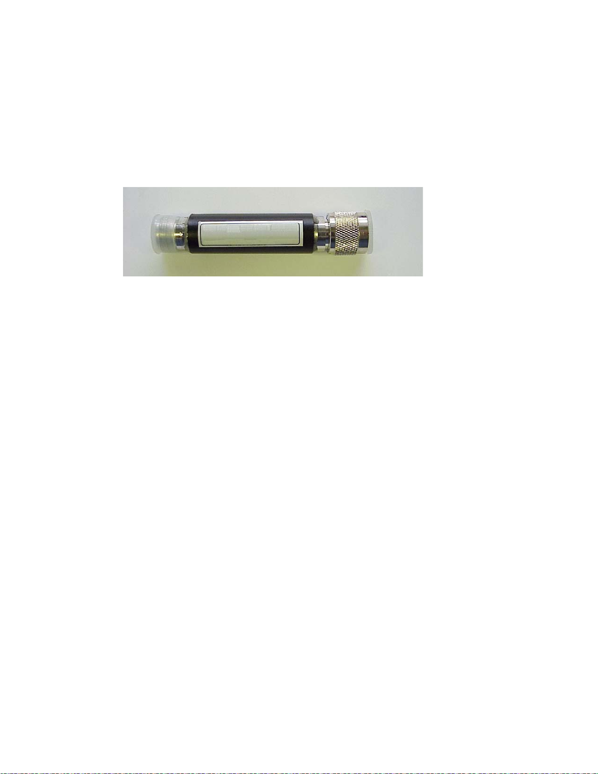
Chapter 3: MOTOMESH Duo Hardware
BandPass Filter
The BandPass filter should be used when using a MOTOMESH DUO device together with a
Motorola Canopy backhaul radio while operating in the 5.2, 5.4, or 5.8GHz range.
The specific 5.2, 5.4, or 5.8 BandPass filter attaches to the applicable 4.9, 5.4, and 5.8
antenna socket, positioned between the unit and the antenna.
Figure 3-10 BandPass Filter (Part # 9163340B01)
3-11
Page 59

Chapter 3: MOTOMESH Duo Hardware
This page intentionally left blank.
3-12
Page 60

Chapter 4: Site Selection and Deployment Guidelines
Chapter
4
Chapter 4: Site Selection and Deployment Guidelines
.............................................
.
.
This chapter will provide information on how to assemble a MOTOMESH Duo device as well as general
guidelines to be observed when evaluating a potential deployment location.
Preparation
MOTOMESH Duo devices must be installed by trained professionals familiar with RF planning and
regulatory limits defined by the country of installation. All common precautions for grounding and ESD
(Electrostatic Discharge) protection should be observed during deployment and installation. MOTOMESH
Duo devices are designed to be installed outdoors and must be installed such that no harmful
interference results from device operation.
All device wiring must follow the National Electric Code (NEC) or wiring requirements in the country of
installation. All location building and structure codes must be observed.
During installation safety precautions must be taken to avoid:
• Exposure to high voltage sources
• Antenna contact with overhead power lines
• Falling tools and or equipment
• Vehicular traffic in and around mounti ng locations
4-1
Page 61

Chapter 4: Site Selection and Deployment Guidelines
Hardware and Tools
Figure 4-1 details MOTOMESH Duo device and accessories.
Figure 4-1 MOTOMESH Duo device with accessories
Included hardware:
• (1) Pivot packet
• (1) antenna bracket
• (2) right angle antenna connectors
• (2) 7mm hex bolts to secure antenna bracket
The following tools will be required:
• 7/16 wrench
• Adjustable wrench
• 7 mm allen wrench
4-2
Page 62

Chapter 4: Site Selection and Deployment Guidelines
• Phillips head screwdriver
• Level
• Weatherproofing tape
• Electrical tape
Figure 4-2 Required Tools
Opening the MOTOMESH Duo device will void the warranty.
Device Assembly
Procedure 4-1 Device assembly
Using the 7/16” wrench position the mounting bracket. There are four possible positions. Figure 4-3
shows the recommended bracket position for mounting the device such that both antennas are facing
upward. This is the recommended configuration.
Figure 4-3 Attaching the mounting bracket
4-3
Page 63

Chapter 4: Site Selection and Deployment Guidelines
Loosen the pivot screw so the bracket is free to rotate.
Figure 4-4 Loosing the pivot screw
=
Remove both antenna caps.
Figure 4-5 Remove the antenna caps
4-4
Page 64

Chapter 4: Site Selection and Deployment Guidelines
Attach the right angle antenna connectors.
Figure 4-6 Attaching the right angle antenna connectors
Your MOTOMESH Duo device should now look like this.
Figure 4-7 MOTOMESH Duo device with right angle antenna connectors installed
4-5
Page 65

Chapter 4: Site Selection and Deployment Guidelines
Remove the bracket clamp with the 7mm wrench.
Figure 4-8 Removing the bracket clamp
If using the 2.4 GHz down tilt antenna (which has a larger base) angle the bracket to fit around the base
of the antenna.
Figure 4-9 Attaching the bracket
4-6
Page 66

Chapter 4: Site Selection and Deployment Guidelines
Slide the other antenna through the bracket.
Figure 4-10 Slide the 5.4, 5.8 or 4.9 antenna through the bracket
Carefully tighten both antennas. Do not over tighten. Never tighten the antennas by the plastic radome.
Figure 4-11 Tighten the antennas
4-7
Page 67
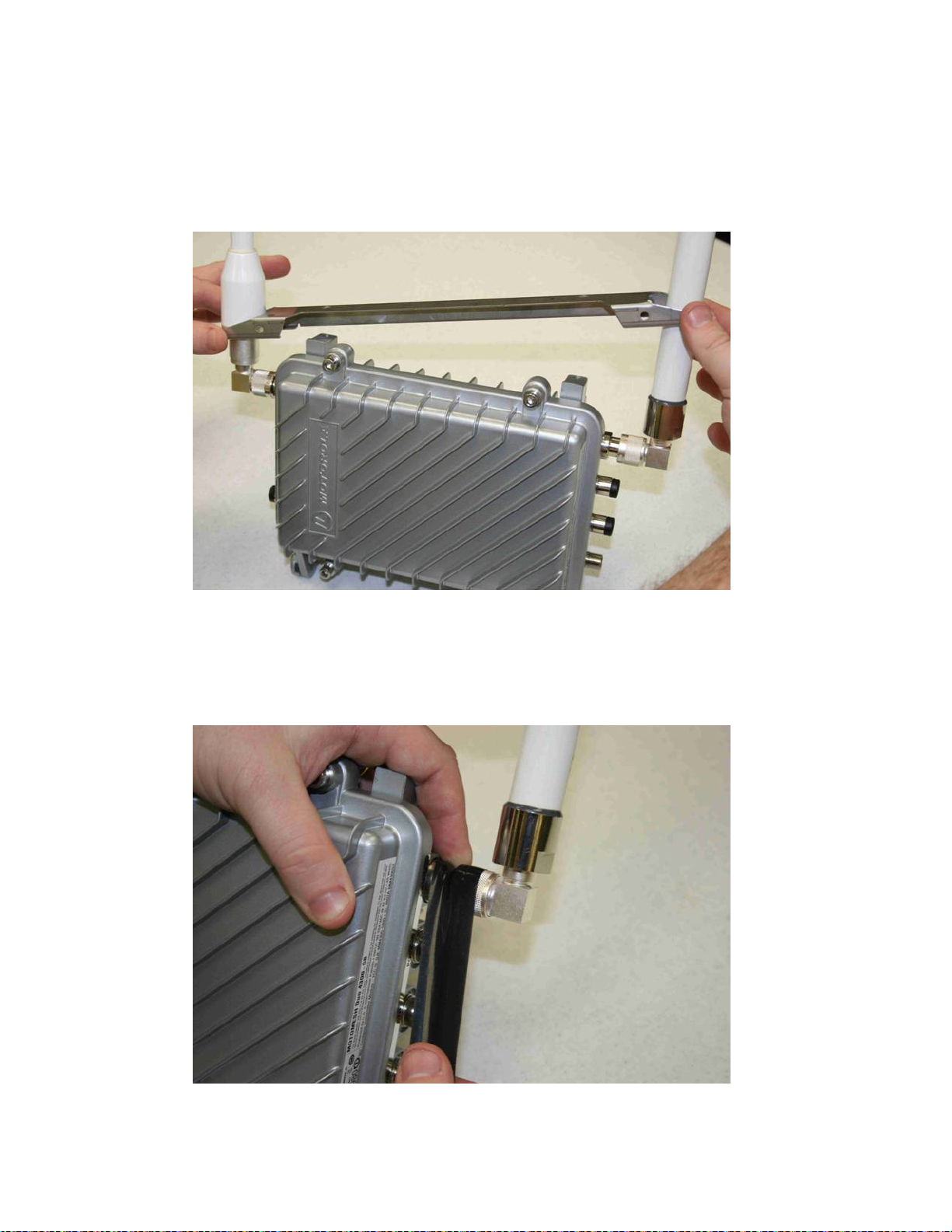
Chapter 4: Site Selection and Deployment Guidelines
Slide the bracket up to make additional room to apply the weatherproof tape.
Figure 4-12 Slide the bracket up
Stretch the weatherproof tape around the antenna connector
Figure 4-13 Apply the weatherproof tape
4-8
Page 68

Chapter 4: Site Selection and Deployment Guidelines
Figure 4-14 Finish wrapping the tape around the antenna base
If using an antenna with vent holes above the antenna base (e.g. the 2.4 GHz downtilt antenna) do not
tape over the vent holes.
Figure 4-15 Repeat this on the other antenna
4-9
Page 69

Chapter 4: Site Selection and Deployment Guidelines
Figure 4-16 Use electrical tape and cover the weatherproof tape
Figure 4-17 Tighten the antenna bracket
4-10
Page 70

Chapter 4: Site Selection and Deployment Guidelines
Figure 4-18 Tighten the bracket screws
If your MOTOMESH Duo device is going to be used as an IAP remove the protective cap on the POE
OPT Ethernet port. The POE OPT port is configured by default to be used as the backhaul port. Note
that this port is NOT powered unless a personality plug is attached to the select port. Please see Chapter
3 for more information. Note that the Ethernet cable and port are keyed.
Figure 4-19 Remove the protective cap
4-11
Page 71

Chapter 4: Site Selection and Deployment Guidelines
Connect the 4 pin power cable to the power port. Note that the cable is keyed.
Figure 4-20 Attach the 8 pin cable Ethernet cable
Figure 4-21 Connecting the power cable
4-12
Page 72

Chapter 4: Site Selection and Deployment Guidelines
Figure 4-22 Apply weatherproof tape to the Ethernet and power connectors
Figure 4-23 Finished MOTOMESH Duo device
4-13
Page 73

Chapter 4: Site Selection and Deployment Guidelines
The majority of your MOTOMESH Duo devices will only have a power connection (unless the device is an
IAP). If the MWR is going to be used to power a PoE capable device (such as an IP camera) then add
the white personality plug to the select port (standards based 802.3af PoE) and connect the Ethernet
cable to the POE OPT port.
Figure 4-24 shows a MOTOMESH Duo mounted on a horizontal pole. The mounting bracket is tightened
using the 7/16” wrench.
Figure 4-24 Mounted MOTOMESH Duo
4-14
Page 74

Chapter 4: Site Selection and Deployment Guidelines
Site Selection Guidelines
.............................................
.
The following recommendations should be given primary consideration in accessing potential
sites for deployment;
1. Device locations should be chosen in areas such that radio signals will not be
obstructed by trees, buildings or other structures.
2. Device locations should be chosen away from other in band radio sources. This
includes other products operating in the 2.4 GHz, 4.9 GHz, 5.X GHz radio bands, and
weather radar sources.
3. Device locations should be chosen such that antennas are at least 30 inches from
any nearby metal poles to avoid distortion of the RF pattern. The antenna must also
have a separation distance of at least 2 meters from the body of all persons and must
not be co-located or operating in conjunction with any other antenna or transmitter.
4. Choose locations that have AC or DC power readily available.
5. Consider the time of year. During the winter months a location may be free of foliage
that will return in the warmer months to obstruct the device antennas.
6. When choosing locations consider the proper permits required for mounting on
structures that are publicly or privately owned.
7. Choose locations that provide direct line-of-sight conditions such as those along main
roadways. Intersections often provide the best mounting options. Nominal 0.25 -
0.35 miles line-of-sight between infrastructure devices.
8. The IAP locations should be determined first since they control the critical function of
routing information back to your wired network infrastructure. This may be done via
an Ethernet cable if the IAP is located within 100 meters (the max length permitted
for standard Ethernet) of each other. If the distance is greater than 100 meters, a
mechanism for extending the Ethernet connection will be required, e.g., using fiber,
Motorola Canopy backhaul radio.
9. Once the optimal locations for the IAPs have been identified, the location of the
MWRs can be determined. Ideally, devices should be distributed such that any
subscriber is no more than 3 hops to an IAP.
Site Surveys
It is strongly suggested that an RF site survey be performed during site selection. The uses of tools such
as Motorola’s MeshPlanner™ or an RF scanner are highly recommended. Consider the following when
performing your site survey:
• At each potential mounting location determine the number of access points operating on
the non overlapping channels (e.g. 2.4 GHz 1, 6, and 11).
• If possible obtain RF samples at the approximate height in which devices will be
located. This can often be safely done with a tripod mounted scanning antenna.
4-15
Page 75

Chapter 4: Site Selection and Deployment Guidelines
• Consider taking RF sweeps at different times of the day to determine if intermittent
interferers exist.
Device Mounting
MOTOMESH Duo can be mounted with two different antenna orientations. The
recommended mounting configuration utilizes the antenna bracket (with right angle
connectors) with both antennas orientated upward. If the bracket is not used one radio
antenna must be pointed upward and the other downward. In either mounting scenario the
antennas must be mounted in the vertical plane.
Use a level to ensure the antennas are level.
Figure 4-25 Mounting Options
If a device is mounted in the configuration without the antenna bracket, and a 2.4 GHz
downtilt antenna is used, the 2.4 GHz antenna must be installed facing upward.
Observe the following additional guidelines when deploying fixed Infrastructure Devices:
• Attach the antenna bracket, right angle connectors, and antenna prior to
mounting the device.
4-16
Page 76

Chapter 4: Site Selection and Deployment Guidelines
• MOTOMESH Duo devices may be mounted on a pole having a diameter of 1-
3.5 inches, utilizing the pivot mounting bracket.
• Users and installers must be provided with antenna installation and transmitter
operating conditions to satisfy RF exposure compliance.
• The IAP
infrastructure.
• Type A-Light Duty sites have impedance requirements of 25 ohms or less to
ground whereas Type B- Light Industrial/Commercial sites have impedance
requirements of less than 5 ohms to ground. MOTOMESH Duo 2.1 networks fall
into the Type B-Light Industrial/Commercial category, and therefore must be
treated with greater considerations as far as grounding requirements are
concerned.
MUST have an Ethernet connection to your wired network
Street Lights
If the MOTOMESH Duo device is attached to a light arm and the attachment point meets the Type B
grounding requirements, then the grounding stud attachment point is not required to be used. Since Type
B grounding requirements stipulate 5 ohms or less impedance to earth ground, things such as soil pH,
type of grounding rods, size of conductors, and ground enhancing materials must be taken into account to
achieve this goal. To verify the impedance requirements are met, a special Earth/Ground Resistance
Tester (megohmmeter) may be necessary.
MOTOMESH Duo devices should be mounted on the horizontal arm of the streetlight. If this cannot be
accomplished then a stand off bracket should be used to ensure adequate separation from the pole and
additional grounding must be supplied.
When using a photocell power cable you must verify that street light power is between 90-264
VAC.
Roof Mount
When mounting on roof tops care must be taken to ensure devices are not significantly higher than
surrounding devices. Devices mounted at larger heights are more vulnerable to
are also more susceptible to interference. When mounting on the side of a building make sure a standoff
bracket is used to provide adequate separation between the building surface and the MOTOMESH Duo
device. These mounts can be obtained through a variety of distributors.
4-17
lightning strikes. They
Page 77

Chapter 4: Site Selection and Deployment Guidelines
Figure 4-26 Standoff bracket
Antenna Height
It is important to consider device height. For optimal performance, devices should be mounted at similar
heights. Large height mismatches will result in nearby devices not seeing each other. This can produce
additional mesh hops which may be undesirable. In Figure 4-27, traffic from Wi-Fi clients connecting to
the MWR on pole 1 will have to hop through the MWR on pole 2 to reach the IAP on building A.
Figure 4-27 Antenna Heights
Building A
Pole 1
Pole 2
4-18
Page 78

Chapter 4: Site Selection and Deployment Guidelines
Figure 4-28 Antenna Patterns
Building A
IAP Antenna Coverage Pattern
MWR mounted at different
antenna height from IAP.
Weak side lobes align
Pole 1
Pole 2
MWRs mounted at same
antenna height.
Strong center lobes align
Mounting Examples
When mounting a MOTOMESH Duo device it is very important to consider the previously discussed
location guidelines. The following examples represent poor choices in device location.
Figure 4-29 Poor Install Example 1
Perhaps this location looked ok during the winter months…..
4-19
Page 79

Chapter 4: Site Selection and Deployment Guidelines
Figure 4-30 Poor Install Example 2
In this example we see the Canopy backhaul radio with its antenna pointing towards the
MOTOMESH Duo device. This results in strong interference.
Figure 4-31 Poor Install Example 3
In this example we see the MOTOMESH Duo device mounted with its antenna next to a
steel pole. This results in antenna pattern distortion.
4-20
Page 80

Chapter 5: Customer Information
Chapter 5: Customer Information
.............................................
.
.
.
.
This chapter provides Customer Service Information and the Motorola Software License
Terms and Conditions.
Customer Service Information
.............................................
.
.
Chapter
5
If you have read this document and made every effort to resolve installation or operation
issues yourself and still require help, please contact your regional Motorola support
representatives
USA
Motorola System Support Center (SSC) using the following contact information:
Phone: 800-221-7144
Hours of Operation: 7 days a week, 24 hours
Europe
Phone: +44 (0)1793 564680
Email:
Hours: of Operation: Mon-Fri 09:00 - 17:00 GMT
Calls are logged 24 x 7, cases will be worked Mon-Fri 09:00 - 17:00 GMT
Asia and Pacific Region
Remote Technical Help Desk (Channel Partners)
Phone: +63 28 92 79 93
Email: 199H
198Hessc@motorola.com
wi4Tech@motorola.com
Hours of Operation: Mon - Fri 8 am - 6 pm
Sat 8 am - 12 noon
5-1
Page 81

Chapter 5: Customer Information
Obtaining Support
Motorola provides technical support services for your system and recommends that you
coordinate warranty and repair activities through the Motorola System Support Center (SSC).
When you consult the Motorola SSC, you increase the likelihood that problems are rectified in
a timely fashion and that warranty requirements are satisfied. Check your contract for specific
warranty and service information.
System Information
To be provided with the best possible opportunity for support, collect the following system
information and have it available when obtaining support.
• Location of the system
• Date the system was put into service
• Software or firmware version information for components of your system
• Serial number(s) of the device(s) or component(s) requiring support
• A written description of the symptom or observation of the problem:
- When did it first appear?
- Can it be reproduced?
- What is the step-by-step procedure to cause it?
• Do other circumstances contribute to the problem? For example, changes in
weather or other conditions?
• Maintenance action preceding problem:
- Upgrade of software or equipment
- Change in the hardware or software configuration
- Software reload - from backup or from CD-ROM (note the version and date)
Return Material Request
After collecting system information, contact the Motorola System Support Center for
assistance or to obtain a Return Material Authorization (RMA) number for faulty Field
Replaceable Entities (FREs):
North America: 800-221-7144, Radio Products and Services Division
The Radio Products and Services Division is your source for manuals and replacement parts.
Radio Products and Services Division Telephone Numbers
The telephone numbers for ordering are: (800)-422-4210 (US and Canada orders)
The Fax numbers are: (800)-622–6210 (US and Canada orders)
5-2
Page 82

Chapter 5: Customer Information
The number for help identifying an item or part number is (800)-422-4210; select choice “3”
from the menu
Returning FREs
Return faulty FREs to Motorola for repair. When you return an assembly for service, follow
these best practices:
• Place any assembly containing CMOS devices in a static-proof bag or container
for shipment.
• Obtain a return authorization (RA) number from the Motorola System Support
Center.
• Include the warranty, model, kit numbers, and serial numbers on the job ticket,
as necessary.
• If the warranty is out of date, you must have a purchase order.
• Print the return address clearly, in block letters.
• Provide a phone number where your repair technician can be reached.
• Include the contact person's name for return.
• Pack the assembly tightly and securely, preferably in its original shipping
container.
Software License Terms and Conditions
.............................................
.
.
ONLY OPEN THE PACKAGE, OR USE THE SOFTWARE AND RELATED PRODUCT IF
YOU ACCEPT THE TERMS OF THIS LICENSE. BY BREAKING THE SEAL ON THIS DISK
KIT / CDROM, OR IF YOU USE THE SOFTWARE OR RELATED PRODUCT, YOU ACCEPT
THE TERMS OF THIS LICENSE AGREEMENT. IF YOU DO NOT AGREE TO THESE
TERMS, DO NOT USE THE SOFTWARE OR RELATED PRODUCT; INSTEAD, RETURN
THE SOFTWARE TO PLACE OF PURCHASE FOR A FULL REFUND. THE FOLLOWING
AGREEMENT IS A LEGAL AGREEMENT BETWEEN YOU (EITHER AN INDIVIDUAL OR
ENTITY), AND MOTOROLA, INC. (FOR ITSELF AND ITS LICENSORS). THE RIGHT TO
USE THIS PRODUCT IS LICENSED ONLY ON THE CONDITION THAT YOU AGREE TO
THE FOLLOWING TERMS. Now, therefore, in consideration of the promises and mutual
obligations contained herein, and for other good and valuable consideration, the receipt and
sufficiency of which are hereby mutually acknowledged, you and Motorola agree as follows:
Grant of License. Subject to the following terms and conditions, Motorola, Inc., grants to you
a personal, revocable, non-assignable, non-transferable, non-exclusive and limited license to
use on a single piece of equipment only one copy of the software contained on this disk
(which may have been pre-loaded on the equipment)(Software). You may make two copies of
the Software, but only for backup, archival, or disaster recovery purposes. On any copy you
5-3
Page 83

Chapter 5: Customer Information
make of the Software, you must reproduce and include the copyright and other proprietary
rights notice contained on the copy we have furnished you of the Software.
Ownership. Motorola (or its supplier) retains all title, ownership and intellectual property
rights to the Software and any copies, including translations, compilations, derivative works
(including images) partial copies and portions of updated works. The Software is Motorola’s
(or its supplier's) confidential proprietary information. This Software License Agreement does
not convey to you any interest in or to the Software, but only a limited right of use. You agree
not to disclose it or make it available to anyone without Motorola’s written authorization. You
will exercise no less than reasonable care to protect the Software from unauthorized
disclosure. You agree not to disassemble, decompile or reverse engineer, or create
derivative works of the Software, except and only to the extent that such activity is expressly
permitted by applicable law.
Termination. This License is effective until terminated. This License will terminate
immediately without notice from Motorola or judicial resolution if you fail to comply with any
provision of this License. Upon such termination you must destroy the Software, all
accompanying written materials and all copies thereof, and the sections entitled Limited
Warranty, Limitation of Remedies and Damages, and General will survive any termination.
Limited Warranty. Motorola warrants for a period of ninety (90) days from Motorola’s or its
customer’s shipment of the Software to you that (i) the disk(s) on which the Software is
recorded will be free from defects in materials and workmanship under normal use and (ii) the
Software, under normal use, will perform substantially in accordance with Motorola’s
published specifications for that release level of the Software. The written materials are
provided "AS IS" and without warranty of any kind. Motorola's entire liability and your sole
and exclusive remedy for any breach of the foregoing limited warranty will be, at Motorola's
option, replacement of the disk(s), provision of downloadable patch or replacement code, or
refund of the unused portion of your bargained for contractual benefit up to the amount paid
for this Software License.
THIS LIMITED WARRANTY IS THE ONLY WARRANTY PROVIDED BY MOTOROLA, AND
MOTOROLA AND ITS LICENSORS EXPRESSLY DISCLAIM ALL OTHER WARRANTIES,
EITHER EXPRESS OF IMPLIED, INCLUDING BUT NOT LIMITED TO IMPLIED
WARRANTIES OF MERCHANTABILITY AND FITNESS FOR A PARTICULAR PURPOSE
AND NONINFRINGEMENT. MOTOROLA DOES NOT WARRANT THAT THE OPERATION
OF THE SOFTWARE WILL BE UNINTERRUPTED OR ERROR-FREE, OR THAT DEFECTS
IN THE MOTOROLA OR AN AGENT THEREOF SHALL CREATE A WARRANTY OR IN
ANY WAY INCREASE THE SCOPE OF THIS WARRANTY. MOTOROLA DOES NOT
WARRANT ANY SOFTWARE THAT HAS BEEN OPERATED IN EXCESS OF
SPECIFICATIONS, DAMAGED, MISUSED, NEGLECTED, OR IMPROPERLY INSTALLED.
BECAUSE SOME JURISDICTIONS DO NOT ALLOW THE EXCLUSION OR LIMITATION
OF IMPLIED WARRANTIES, THE ABOVE LIMITATIONS MAY NOT APPLY TO YOU.
Limitation of Remedies and Damages. Regardless of whether any remedy set forth herein
fails of its essential purpose, IN NO EVENT SHALL MOTOROLA OR ANY OF THE
LICENSORS, DIRECTORS, OFFICERS, EMPLOYEES OR AFFILIATES OF THE
FOREGOING BE LIABLE TO YOU FOR ANY CONSEQUENTIAL, INCIDENTAL, INDIRECT,
SPECIAL OR SIMILAR DAMAGES WHATSOEVER (including, without limitation, damages
for loss of business profits, business interruption, loss of business information and the like),
whether foreseeable or unforeseeable, arising out of the use or inability to use the Software
or accompanying written materials, regardless of the basis of the claim and even if Motorola
5-4
Page 84

Chapter 5: Customer Information
or a Motorola representative has been advised of the possibility of such damage. Motorola's
liability to you for direct damages for any cause whatsoever, regardless of the basis of the
form of the action, will be limited to the price paid for the Software that caused the damages.
THIS LIMITATION WILL NOT APPLY IN CASE OF PERSONAL INJURY ONLY WHERE
AND TO THE EXTENT THAT APPLICABLE LAW REQUIRES SUCH LIABILITY. BECAUSE
SOME JURISDICTIONS DO NOT ALLOW THE EXCLUSION OR LIMITATION OF LIABILITY
FOR CONSEQUENTIAL OR INCIDENTAL DAMAGES, THE ABOVE LIMITATION MAY NOT
APPLY TO YOU.
Maintenance and Support. Motorola shall not be responsible for maintenance or support of
the software. By accepting the license granted under this agreement, you agree that Motorola
will be under no obligation to provide any support, maintenance or service in connection with
the Software or any application developed by you. Any maintenance and support of the
Related Product will be provided under the terms of the agreement for the Related Product.
Transfer. In the case of software designed to operate on Motorola equipment, you may not
transfer the Software to another party except: (1) if you are an end-user, when you are
transferring the Software together with the Motorola equipment on which it operates; or 2) if
you are a Motorola licensed distributor, when you are transferring the Software either
together with such Motorola equipment or are transferring the Software as a licensed duly
paid for upgrade, update, patch, new release, enhancement or replacement of a prior version
of the Software. If you are a Motorola licensed distributor, when you are transferring the
Software as permitted herein, you agree to transfer the Software with a license agreement
having terms and conditions no less restrictive than those contained herein. You may transfer
all other Software, not otherwise having an agreed restriction on transfer, to another party.
However, all such transfers of Software are strictly subject to the conditions precedent that
the other party agrees to accept the terms and conditions of this License, and you destroy
any copy of the Software you do not transfer to that party. You may not sublicense or
otherwise transfer, rent or lease the Software without our written consent. You may not
transfer the Software in violation of any laws, regulations, export controls or economic
sanctions imposed by the US Government.
Right to Audit. Motorola shall have the right to audit annually, upon reasonable advance
notice and during normal business hours, your records and accounts to determine
compliance with the terms of this Agreement.
Export Controls. You specifically acknowledge that the software may be subject to United
States and other country export control laws. You shall comply strictly with all requirements of
all applicable export control laws and regulations with respect to all such software and
materials.
US Government Users. If you are a US Government user, then the Software is provided
with "RESTRICTED RIGHTS" as set forth in subparagraphs (c)(1) and (2) of the Commercial
Computer Software-Restricted Rights clause at FAR 52 227-19 or subparagraph (c)(1)(ii) of
the Rights in Technical Data and Computer Software clause at DFARS 252.227-7013, as
applicable.
Disputes. You and Motorola hereby agree that any dispute, controversy or claim, except for
any dispute, controversy or claim involving intellectual property, prior to initiation of any
formal legal process, will be submitted for non-binding mediation, prior to initiation of any
formal legal process. Cost of mediation will be shared equally. Nothing in this Section will
prevent either party from resorting to judicial proceedings, if (i) good faith efforts to resolve
the dispute under these procedures have been unsuccessful, (ii) the dispute, claim or
5-5
Page 85

Chapter 5: Customer Information
controversy involves intellectual property, or (iii) interim relief from a court is necessary to
prevent serious and irreparable injury to that party or to others.
General. Illinois law governs this license. The terms of this license are supplemental to any
written agreement executed by both parties regarding this subject and the Software Motorola
is to license you under it, and supersedes all previous oral or written communications
between us regarding the subject except for such executed agreement. It may not be
modified or waived except in writing and signed by an officer or other authorized
representative of each party. If any provision is held invalid, all other provisions shall remain
valid, unless such invalidity would frustrate the purpose of our agreement. The failure of
either party to enforce any rights granted hereunder or to take action against the other party
in the event of any breach hereunder shall not be deemed a waiver by that party as to
subsequent enforcement of rights or subsequent action in the event of future breaches.
5-6
Page 86

Chapter 5: Customer Information
This page intentionally left blank.
5-7
Page 87

Chapter 6: Certification and Safety Information
Chapter 6: Certification and Safety Information
.............................................
.
.
.
.
This chapter lists the relevant FCC Certification and Product Safety Information for the
MOTOMESH Duo 2.1 devices described in this manual.
Chapter
6
FCC Regulatory Information
.............................................
.
.
This device complies with Part 15 of the FCC Rules. Operation is subject to the following two
conditions: (1) this device may not cause harmful interference, and (2) this device must
accept any interference received; including interference that may cause undesired operation.
The IAP (Intelligent Access Point) is an infrastructure device that is positioned at a fixed
location such as a building rooftop.
The MWR (Mesh Wireless Router) is an infrastructure device positioned in a fixed location,
such as on a pole, wall, or rooftop. The MWR requires professional installation to ensure the
installation is performed in accordance with FCC licensing regulations.
Federal Communications Commission (FCC) Statement
Intelligent Access Point/Mesh Wireless Router
This equipment has been tested and found to comply with the limits for a Class A digital
device, pursuant to part 15 of the FCC Rules. These limits are designed to provide
reasonable protection against harmful interference when the equipment is operated in a
commercial environment. This equipment generates, uses, and can radiate radio frequency
energy and, if not installed and used in accordance with the instruction manual, may cause
harmful interference to radio communications. Operation of this equipment in a residential
area is likely to cause harmful interference in which case the user will be required to correct
the interference at his own expense.
6-1
Page 88

Chapter 6: Certification and Safety Information
Safety Information for the MOTOMESH Products
.............................................
.
.
The Federal Communications Commission (FCC) with its action in ET Docket 96-8 has
adopted a safety standard for human exposure to radio frequency (RF) electromagnetic
energy emitted by FCC certified equipment. Motorola MOTOMESH products meet the
uncontrolled environmental limits found in OET-65 and ANSI C95.1, 1991. Proper operation
of this radio according to the instructions found in this manual and the hardware and software
guides on the MOTOMESH CD will result in user exposure that is substantially below the
FCC recommended limits.
• Do not touch or move the antenna(s) while the unit is transmitting or receiving.
• Do not hold any component containing a radio such that the antenna is very
close to or touching any exposed parts of the body, especially the face or eyes,
while transmitting.
• Do not operate a portable transmitter near unshielded blasting caps or in an
explosive environment unless it is a type especially qualified for such use.
• Do not operate the radio or attempt to transmit data unless the antenna is
connected; otherwise, the radio may be damaged.
FCC Radiation Exposure Statement
This equipment complies with FCC radiation exposure limits set forth for an uncontrolled
environment. This equipment should be installed and operated with minimum distance of 20
cm between the radiator and your body.
Safety Certification
Conforms to UL STD ANSI/UL 60950 3
• Certified to CAN/CSA C22.2 NO. 60950-00
Equipment shall be suitable for use in Air pressure: 86kPa to106kPa.
rd
Edition
6-2
Page 89

Chapter 6: Certification and Safety Information
Regulatory Requirements and Legal Notices
.............................................
.
.
Regulatory Requirements for CEPT Member States
(
www.cept.org)
When operated in accordance with the instructions for use, Motorola MOTOMESH Wireless
equipment operating in the 2.4 and 5.4 GHz bands is compliant with CEPT Recommendation
70-03 Annex 3 for Wideband Data Transmission and HIPERLANs. For compliant operation in
the 2.4 GHz band, the transmit power (EIRP) from the antenna shall be no more than 100mW
(20dBm). For compliant operation in the 5.4 GHz band, the transmit power (EIRP) from the
antenna shall be no more than 1 W (30 dBm).
The following countries have completely implemented CEPT Recommendation 70-03 Annex
3A (2.4 GHz band):
• EU & EFTA countries: Austria, Belgium, Denmark, Spain, Finland, Germany,
Greece, Iceland, Italy, Ireland, Liechtenstein, Luxembourg, Netherlands,
Norway, Portugal, Switzerland, Sweden, UK
• New EU member states: Bulgaria, Czech Republic, Cyprus, Estonia, Hungary,
Lithuania, Latvia, Malta, Poland, Slovenia, Slovakia
• Other non-EU & EFTA countries: Bosnia and Herzegovina, Turkey
The following countries have a limited implementation of CEPT Recommendation 70-03
Annex 3A:
• France - Outdoor operation at 100mW is only permitted in the frequency band
2400 to 2454 MHz;
Any outdoor operation in the band 2454 to 2483.5MHz shall not exceed
10mW (10dBm);
Indoor operation at 100mW (20dBm) is permitted across the band 2400 to
2483.5 MHz
• French Overseas Territories:
Guadeloupe, Martinique, St Pierre et Miquelon, Mayotte – 100mW indoor &
outdoor is allowed
Réunion and Guyana – 100mW indoor, no operation outdoor in the band
2400 to 2420MHz
• Italy - If used outside own premises, general authorization required
• Luxembourg - General authorization required for public service
• Romania - Individual license required. T/R 22-06 not implemented
Motorola MOTOMESH Radios operating in the 2400 to 2483.5MHz band are categorized as
“Class 2” devices within the EU and are marked with the class identifier symbol
that national restrictions apply (for example, France). The French restriction in the 2.4 GHz
band will be removed in 2011. This 2.4 GHz equipment is “CE” marked
6-3
, denoting
to
Page 90

Chapter 6: Certification and Safety Information
show compliance with the European Radio & Telecommunications Terminal Equipment
(R&TTE) directive 1999/5/EC and that National restrictions apply.
Where necessary, the end user is responsible for obtaining any National licenses required to
operate this product and these must be obtained before using the product in any particular
country. However, for CEPT member states, 2.4 GHz Wideband Data Transmission
equipment has been designated exempt from individual licensing under decision
ERC/DEC(01)07. For EU member states, RLAN equipment in both the 2.4 & 5.4GHz bands
is exempt from individual licensing under Commission Recommendation 2003/203/EC.
Contact the appropriate national administrations for details on the conditions of use for the
bands in question and any exceptions that might apply. Also see
information.
Motorola MOTOMESH dual Radio equipment operating in the 5470 to 5725 MHz band also
operates in the 2400 to 2483.5MHz band and is categorized as “Class 2” devices within the
EU because of the additional 2.4GHz radio. These devices will become “Class 1” devices
after 2011 when the restrictions on the 2.4GHz band are removed but are currently “CE”
http://www.ero.dk for further
marked
Telecommunications Terminal Equipment (R&TTE) directive 1999/5/EC and that National
restrictions apply.
Relevant Declarations of Conformity can be found at
http://motorola.canopywireless.com/doc.php
to show compliance with the European Radio &
European Union Notification
The CE mark is the official marking required by the European Community for all Electric and
Electronic equipment that will be sold, or put into service for the first time, anywhere in the
European community. It proves to the buyer or user that this product fulfills all essential
safety and environmental requirements as they are defined in the European Directives.
Motorola Products are covered under the following product certification Europe:
ETSI EN 300 328 V 141 (2003-04)
ETSI EN 301 489-1 (2002-08) and EN 301 489-17
EN 55022:1998 and EN 55024:1998
CENELEC EN 50360 and EN50371 – Specific Absorption Test – SAR
European Union Notification 5.7GHz Product
The 5.7 GHz MOTOMESH is a Class 2 device and uses operating frequencies that are not
harmonized throughout the EU member states. The operator is responsible for obtaining any
national licenses required to operate this product and these must be obtained before using
the product in any particular country. The 5.7GHz MOTOMESH dual radio products also
operate in the 2.4GHz band – see other sections of this document for restrictions on
operating in the 2.4GHz band.
6-4
Page 91
Chapter 6: Certification and Safety Information
This equipment is marked to show compliance with the European R&TTE
directive 1999/5/EC and that National restrictions apply.
The relevant Declaration of Conformity can be found at
http://motorola.canopywireless.com/doc.php
Annex 6 – Instructions for use (regulatory content)
MOTOMESH 2.4/5.8 GHz Radio
European Union Notification
The CE mark is the official marking required by the European Community for all Electric and
Electronic equipment that will be sold, or put into service for the first time, anywhere in the
European community. It proves to the buyer or uses that this product fulfills all essential
safety and environmental requirements as they are defined in the European Directives.
The 2.4GHz/5.8GHz product range marked with the following CE marks,
Carry the alert symbol
member states. Products marked with both these CE numbers are
the following EU member states: -
• Ireland
• Norway
• UK
The CE mark acknowledges that the product is in compliance with regulations of the
European Radio & Telecommunications Terminal Equipment (R&TTE) directive 1999/5/EC
and other relevant directives. See section Declaration of Conformity section (found later in
this chapter) with the applicable directives.
Note: This product only operates in the following channels (20MHz channel size) in the
5.8GHz band.
Channel
Number
1321
to denote the product is not suitable for deployment in all EU
Frequency (MHz)
149 5745
&
only suitable for use in
153 5765
157 5785
161 5805
1
For use in the UK, Republic of Ireland, and Norway, the frequency range 5795-5815 MHZ
shall not be used and should be notched out to protect RTTT devices. Users must therefore
1
6-5
Page 92

Chapter 6: Certification and Safety Information
NOT select channel 161 as an operational channel to conform to National Licensing
requirements.
Note: For use in the Republic of Ireland, the maximum transmit power in the 5.8GHz band
shall be less than 33dBm EIRP. Therefore to ensure compliance with National licensing
requirements users of this equipment must ensure the conducted transmit power is set to no
more than 23dBm (10dBi antenna gain).
For the U.K. and Norway this product transmits at a maximum of 34dBm which is less than
the maximum allowed in the 5.8GHz band (36dBm).
Equipment Disposal
Please do not dispose of Electronic and Electric Equipment or Electronic and Electric
Accessories with your household waste. In some countries or regions, collection systems
have been set up to handle waste of electrical and electronic equipment. In European Union
countries, please contact your local equipment supplier representative or service center for
information about the waste collection system in your country.
Waste (Disposal)
of Electronic
and Electric
Equipment
UK Notification
The 5.7 GHz MOTOMESH product has been notified for operation in the UK, and when
operated in accordance with instructions for use it is compliant with UK Interface
Requirement IR2007. For UK use, installations must conform to the requirements of IR2007
in terms of EIRP spectral density against elevation profile above the local horizon in order to
protect Fixed Satellite Services. The frequency range 5795-5815 MHz is assigned to Road
Transport & Traffic Telematics (RTTT) in the U.K. and shall not be used by FWA systems in
order to protect RTTT devices. UK licensing specifies that radiolocation services shall be
protected by a Dynamic Frequency Selection (DFS) mechanism to prevent co-channel
operation in the presence of radar signals.
Belgium Notification
Belgium national restrictions in the 2.4 GHz band include
• EIRP must be lower then 100 mW
• For crossing the public domain over a distance > 300m the user must have the
authorization of the BIPT.
• No duplex working
Luxembourg Notification
6-6
Page 93

Chapter 6: Certification and Safety Information
For the 2.4 GHz band, point-to-point or point-to-multipoint operation is only allowed on
campus areas. 5.4GHz products can only be used for mobile services.
Czech Republic Notification
2.4 GHz products can be operated in accordance with the Czech General License
No. GL-12/R/2000.
5.4 GHz products can be operated in accordance with the Czech General License
No. GL-30/R/2000.
Norway Notification
Use of the frequency bands 5725-5795 / 5815-5850 MHz are authorized with maximum
radiated power of 4 W EIRP and maximum spectral power density of 200 mW/MHz. The
radio equipment shall implement Dynamic Frequency Selection (DFS) as defined in Annex 1
of ITU-R Recommendation M.1652 / EN 301 893. Directional antennae with a gain up to 23
dBi may be used for fixed point-to-point links. The power flux density at the border between
Norway and neighbouring states shall not exceed - 122.5 dBW/m
bandwidth of 1 MHz.
2
measured with a reference
MOTOMESH 5.7GHz products have been notified for use in Norway and are compliant when
configured to meet the above National requirements. Users shall ensure that DFS
functionality is enabled, maximum EIRP respected for a 20 MHz channel, and that channel
spacings comply with the allocated frequency band to protect Road Transport and Traffic
Telematics services (for example, 5735, 5755, 5775 or 5835 MHz are suitable carrier
frequencies).
Greece Notification
The outdoor use of 5470-5725MHz is under license of EETT but is being harmonized
according to the CEPT Decision ECC/DEC/(04) 08, of 12th November 2004. End users are
advised to contact the EETT to determine the latest position and obtain any appropriate
licenses.
6-7
Page 94

Chapter 6: Certification and Safety Information
DECLARATION OF CONFORMITY
Česky [Czech]
Dansk [Danish]
Deutsch
[German]
Nederlands
[Dutch]
English
Motorola tímto prohlašuje, že tento Motorola MOTOMESH Duo 4300-54
series, je ve shodě se základními požadavky a dalšími příslušnými
ustanoveními směrnice 1999/5/ES.
Undertegnede Motorola erklærer herved, at følgende udstyr Motorola
MOTOMESH Duo 4300-54 series, overholder de væsentlige krav og øvrige
relevante krav i direktiv 1999/5/EF
Hiermit erklärt Motorola, dass sich diese Motorola MOTOMESH Duo 4300-54
series, in Übereinstimmung mit den grundlegenden Anforderungen und den
anderen relevanten Vorschriften der Richtlinie 1999/5/EG befindet". (BMWi)
Hiermit erklärt Motorola die Übereinstimmung des Gerätes Motorola
MOTOMESH Duo 4300-54 series, mit den grundlegenden Anforderungen und
den anderen relevanten Festlegungen der Richtlinie 1999/5/EG. (Wien)
Hierbij verklaart Motorola dat het toestel Motorola MOTOMESH Duo 4300-54
series, in overeenstemming is met de essentiële eisen en de andere
relevante bepalingen van richtlijn 1999/5/EG
Bij deze verklaart Motorola dat deze Motorola MOTOMESH Duo 4300-54
series, voldoet aan de essentiële eisen en aan de overige relevante
bepalingen van Richtlijn 1999/5/EC.
Hereby, Motorola, declares that this Motorola MOTOMESH Duo 4300-54
series, is in compliance with the essential requirements and other relevant
provisions of Directive 1999/5/EC.
Eesti [Estonian]
Suomi [Finnish]
Français
[French]
Ελληνική
[Greek]
Käesolevaga kinnitab Motorola seadme Motorola MOTOMESH Duo 4300-54
series, vastavust direktiivi 1999/5/EÜ põhinõuetele ja nimetatud direktiivist
tulenevatele teistele asjakohastele sätetele.
Motorola vakuuttaa täten että Motorola MOTOMESH Duo 4300-54 series,
tyyppinen laite on direktiivin 1999/5/EY oleellisten vaatimusten ja sitä
koskevien direktiivin muiden ehtojen mukainen.
Par la présente Motorola déclare que l'appareil Motorola MOTOMESH Duo
4300-54 series, est conforme aux exigences essentielles et aux autres
dispositions pertinentes de la directive 1999/5/CE
Par la présente, Motorola déclare que ce Motorola MOTOMESH Duo 4300 -
54 series, est conforme aux exigences essentielles et aux autres dispositions
de la directive 1999/5/CE qui lui sont applicables
ΜΕ ΤΗΝ ΠΑΡΟΥΣΑ Motorola ∆ΗΛΩΝΕΙ ΟΤΙ Motorola MOTOMESH Duo
4300-54 series, ΣΥΜΜΟΡΦΩΝΕΤΑΙ ΠΡΟΣ ΤΙΣ ΟΥΣΙΩ∆ΕΙΣ ΑΠΑΙΤΗΣΕΙΣ ΚΑΙ
ΤΙΣ ΛΟΙΠΕΣ ΣΧΕΤΙΚΕΣ ∆ΙΑΤΑΞΕΙΣ ΤΗΣ Ο∆ΗΓΙΑΣ 1999/5/ΕΚ
6-8
Page 95

Chapter 6: Certification and Safety Information
Magyar
[Hungarian]
Íslenska
[Icelandic]
Italiano [Italian]
Latviski
[Latvian]
Lietuvių
[Lithuanian]
Malti [Maltese]
Norsk
[Norwegian]
Alulírott, Motorola nyilatkozom, hogy a Motorola MOTOMESH Duo 4300-54
series, megfelel a vonatkozó alapvetõ követelményeknek és az 1999/5/EC
irányelv egyéb elõírásainak.
Hér með lýsir Motorola yfir því að Motorola MOTOMESH Duo 4300-54
series, er í samræmi við grunnkröfur og aðrar kröfur, sem gerðar eru í
tilskipun 1999/5/EC.
Con la presente Motorola dichiara che questo Motorola MOTOMESH Duo
4300-54 series, è conforme ai requisiti essenziali ed alle altre disposizioni
pertinenti stabilite dalla direttiva 1999/5/CE.
Ar šo Motorola deklarē, ka Motorola MOTOMESH Duo 4300-54 series,
atbilst Direktīvas 1999/5/EK būtiskajām prasībām un citiem ar to saistītajiem
noteikumiem
Šiuo Motorola deklaruoja, kad šis Motorola MOTOMESH Duo 4300-54
series, atitinka esminius reikalavimus ir kitas 1999/5/EB Direktyvos nuostatas
Hawnhekk, Motorola, jiddikjara li dan Motorola MOTOMESH Duo 4300-54
series, jikkonforma mal-ħtiġijiet essenzjali u ma provvedimenti oħrajn relevanti
li hemm fid-Dirrettiva 1999/5/EC
Motorola erklærer herved at utstyret Motorola MOTOMESH Duo 4300-54
series, er i samsvar med de grunnleggende krav og øvrige relevante krav i
direktiv 1999/5/EF.
.
.
Slovensky
[Slovak]
Slovensko
[Slovenian]
Svenska
Swedish
Español
[Spanish]
Polski [Polish]
Português
[Portuguese]
Motorola týmto vyhlasuje, že Motorola MOTOMESH Duo 4300-54 series,
spĺňa základné požiadavky a všetky príslušné ustanovenia Smernice
1999/5/ES
Motorola izjavlja, da je ta Motorola Canopy MOTOMESH Duo 4300-54 series,
v skladu z bistvenimi zahtevami in ostalimi relevantnimi določili direktive
1999/5/ES.
Härmed intygar Motorola att denna Motorola MOTOMESH Duo 4300-54
series, står I överensstämmelse med de väsentliga egenskapskrav och övriga
relevanta bestämmelser som framgår av direktiv 1999/5/EG.
Por medio de la presente Motorola declara que el Motorola MOTOMESH Duo
4300-54 series, cumple con los requisitos esenciales y cualesquiera otras
disposiciones aplicables o exigibles de la Directiva 1999/5/CE
Niniejszym, firma Motorola oświadcza, że produkt serii Motorola MOTOMESH
Duo 4300-54 series, spełnia zasadnicze wymagania i inne istotne
postanowienia Dyrektywy 1999/5/EC.
Motorola declara que este Motorola MOTOMESH Duo 4300-54 series, está
conforme com os requisitos essenciais e outras disposições da Directiva
1999/5/CE.
.
6-9
Page 96

Chapter 6: Certification and Safety Information
EU Declaration of Conformity for RoHS Compliance
Motorola hereby, declares that this Motorola MOTOMESH 4300-xx series is in compliance
with the essential requirements and other relevant provisions of Directive 2002/95/EC,
Restriction of the use of certain Hazardous Substances (RoHS) in electrical and electronic
equipment for the Motorola products listed.
DECLARATION OF CONFORMITY
Motorola declares under it sole responsibility that the products, to which this declaration relates, conform to the
applicable essential requirements of the following Directive(s) of the Council of the European Communities:
• 1999/5/EC of the European Parliament and of the Council of 9 March 1999 on the radio equipment and
telecommunications terminal equipment and the mutual recognition of their conformity (R&TTE Directive).
• 2002/95/EC of the European Parliament and of the Council of 27 January 2003 on the restriction of the use of
certain hazardous substances in electrical and electronic equipment
• 2004/108/EC of 20 July 2007 on the approximation of the laws of the Member States relating to electromagnetic
compatibility (EMC Directive).
• 2006/95/EC on the harmonization of the laws of the Member States relating to electrical equipment designed for
use within certain voltage limits (LV Directive).
• 1999/519/EC of 12 July 1999 on the limitation of exposure of the general public to electromagnetic fields (0 Hz to
300 GHz)
Product: Model: Motorola MOTOMESH Duo 4300-54 and MOTOMESH Duo 4300-54 DC
Model Number Description
HK1599A
HK1717A
HK1598A
HK1720A
Manufacturer: Motorola Inc.
Conformity:
Signature:
Description: Dual Radio transceiver operating in 2.4/5.4GHz band using Atheros AP30 chipset.
Harmonized standards / Methods used to demonstrate conformity: Annex IV of R&TTE using MET
Laboratories Notified Body,
a) Safety – EN 60950-1:2001 + Amendment A11:2004
b) Radio – EN300 328 v1.7.1 & EN301 893 v1.2.3
c) EMC – EN 301 489-1 v1.6.1 & EN 301 489-17 v1.2.1
d) Health – N.B. Statement of Opinion & Test Report 22037 MPE Calculation
Year of first application of CE mark: 2007
______________________ _______________________
Title: Director of Engineering, Title: Quality Director
Mesh Network Product Group
Date: October 29
Name: W. Vann Hasty Name: Laura Phillips
th
Mains (90-264Va.c. 47-63Hz) powered single radio (2.4GHz) assembly
comprising:
• MLUX4019A – 2.4/5.4GHz radio unit (a.c.)
• 8571327H01 – 2.4GHz 8dBi Omni antenna
Mains (90-264Va.c. 47-63Hz) powered dual radio (2.4GHz & 5.4GHz)
assembly comprising:
• MLUX4019A – 2.4/5.4GHz radio unit (a.c.)
• 8571327H01 – 2.4GHz 8dBi Omni antenna
• RAN4044A – 5.4GHz 10dBi Omni antenna
D.C. (10.8 – 14 VDC) powered single radio (2.4GHz) assembly comprising:
• MLUX4023A – 2.4/5.4GHz radio unit (d.c.)
• 8571327H01 – 2.4GHz 8dBi Omni antenna
D.C. (10.8 – 14 VDC) powered dual radio (2.4GHz & 5.4GHz) assembly
comprising:
• MLUX4023A – 2.4/5.4GHz radio unit (d.c.)
• 8571327H01 – 2.4GHz 8dBi Omni antenna
• RAN4044A – 5.4GHz 10dBi Omni antenna
802.11a/b/g
. Certified to meet:-
2007
6-10
Page 97

Chapter 6: Certification and Safety Information
CMM Labeling and Disclosure Table
.............................................
.
.
The People’s Republic of China require that our products comply with China Management
Methods (CMM) environmental regulations. (China Management Methods refers to the
regulation Management Methods for Controlling Pollution by Electronic Information Products
Two items are used to demonstrate compliance; the Label and Disclosure Table.
The label is placed in a customer visible position on the product. The first of the following
examples means that the product contains no hazardous substances; the second means that
the product contains hazardous substances, and has an Environmental Friendly Use Period
(EFUP) of fifty years.
The Environmental Friendly Use Period (EFUP) is the period (in years) during which the
Toxic and Hazardous substances (T&HS) contained in the Electronic Information Product
(EIP) will not leak or mutate causing environmental pollution, or bodily injury from use of the
EIP.
The Disclosure Table, printed in simple Mandarin, is included with each customer order. An
example of the Disclosure Table follows, in both Mandarin and English.
6-11
Page 98

Chapter 7: Index
Chapter 7: Index
.............................................
.
.
.
.
Index
A
AC, 7-1
Accessories
Antennas, 3-10
Band pass filter, 3-11
Ethernet Cable, 3-9
Flying lead power cable, 3-7
Personality Plug, 3-5
Power tap adapter, 3-8
Active Ping, 2-14
B
Backdoor Access, 7-3
Backhaul, 2-14
BandPass Filter, 7-13
C
Canopy, 2-9
Certificates
Configuring Automatic Certificate Issuing, 2-
26
Exporting, 2-28
Installing, 2-29
Microsoft Certificate Authority, 2-24
Requesting a server certificate, 2-26
Trusted root, 2-31
Cisco 3750, 2-9, 7-4
Copyrights, iii
Customer Service Information, 5-1
D
DC, 7-1
Defaults, 2-13
Degraded Mode, 2-14
Device Label, 7-1
DHCP, 2-8, 2-9
Disclaimer, iii
G
grounding, 3-6, 3-7
H
Hardware, 3-1
Enclosure Side 1, 3-2
Enclosure Side 2, 3-3
Pivot mounting bracket, 3-4
I
Installing Windows 2003 Support Tools, 2-24
Intelligent Access Point, 1-2, 6-1
IP Directed Broadcasts, 2-9
IP Network Plan, 2-8
L
L3 Switch, 2-7, 2-8, 2-9, 2-11, 7-4
Label, IAP, 7-1
Link Layer, 2-14
Linux Setup Script, 2-19
M
Mesh Wireless Router, 1-3, 6-1
N
Network Servers, 2-5
O
One Point Wireless Manager, 2-22
P
Personality Plug, 4-3
Ping, 2-14
PoE, 6-1
7-1
Page 99

Chapter 7: Index
R
Radius
Client, 2-31
EAP Settings, 2-30
Juniper Steel Belted Radius, 2-27
R0kh configuration, 2-32
Radius client, 2-30
Red Hat, 2-14, 2-15
RedHat
Installation, 2-15
Requirements, 2-15
Reset Plug, 3-6
Restart, 2-26
RoHS, 6-10
S
Secure Mesh, 1-2, 1-3, 2-5, 2-6, 2-7, 2-19, 2-20,
2-25, 2-27, 2-31, 2-32
Small System Reference Design, 2-5
T
TFTP, 2-8, 2-20
Trademarks, iii
V
VLAN
Examples, 2-11
Setup, 2-10
W
Windows Server 2003, 2-6, 2-27
7-2
Page 100

Glossary
Chapter 8: Glossary
.............................................
.
.
.
AAA Server - (Authentication Authorization Accounting server) A network server
used for access control.
AES– Advanced Encryption Service, a new advanced encryption mechanism
using the Counter-Mode/CBC-MAC Protocol (CCMP)
Glossary
CA – Certificate Authority. When a Certificate Authority is part of a network, its
main role is to issue and manage security credentials and public keys to allow for
message encryption.
EAP– Extensible Authentication Protocol
EAP-TTLS – Uses TLS to provide a secure channel for traditional authentication
methods like CHAP, MS-CHAP, MS-CHAP-v2, and MD5 Challenge. This
reduces the certificate requirements and can leverage legacy RADIUS
authentication methods.
EIRP - Equivalent Isotropically Radiated Power or, alternatively, Effective
Isotropic Radiated Power. Applies to radio communications, specifically to the
antenna.
IAP – Intelligent Access Point. An infrastructure device that is a component of the
MOTOMESH Duo 2.x system.
MWR – Mesh Wireless Router is an infrastructure device within the MOTOMESH
Duo 2.x network.
PoE – Power over the Ethernet (optional feature).
R0KH – R0 Key Handler. Component used in MOTOMESH Duo 2.1 Mesh
security.
R0KHID – R0 Key Handler Identification.
RADIUS – (Remote Authentication Dial-In User Service). Considered to be the
de facto standard protocol for authentication servers (AAA servers).
WM – One Point Wireless Manager™
WPA– Wi-Fi Protected Access, Wi-Fi security launched in October 2003. It also
provides a scheme of mutual authentication using either IEEE 802.1X/Extensible
8-1
 Loading...