

Page 1

MOTOMESH 1.2
Mesh Camera System
Setup and Configuration
Guide
October 2006
6881011Y68-B
Page 2

MOTOMESH 1.2 Mesh Camera System Setup and Configuration Guide
This page intentionally left blank.
6881011Y68-B October 2006
ii
Page 3

MOTOMESH 1.2 Mesh Camera System Setup and Configuration Guide
Copyrights
The Motorola products described in this document may include copyrighted Motorola computer programs. Laws in the United
States and other countries reserve for Motorola certain exclusive rights for copyrighted computer programs. Accordingly, any
copyrighted Motorola computer programs contained in the Motorola products described in this document may not be copied or
reproduced in any manner without the express written permission of Motorola. Furthermore, the purchase of Motorola products
shall not be deemed to grant either directly or by implication, estoppels or otherwise, any license under the copyrights, patents or
patent applications of Motorola, except for the normal nonexclusive, royalty-free license to use that arises by operation of law in
the sale of a product.
Disclaimer
Please note that certain features, facilities and capabilities described in this document may not be applicable to or licensed for use
on a particular system, or may be dependent upon the characteristics of a particular mobile subscriber unit or configuration of
certain parameters. Please refer to your Motorola contact for further information.
Trademarks
Motorola, the Motorola logo, and all other trademarks identified as such herein are trademarks of Motorola, Inc. All other
product or service names are the property of their respective owners.
Copyrights
© 2006 Motorola, Inc. All rights reserved. No part of this document may be reproduced, transmitted, stored in a retrieval system,
or translated into any language or computer language, in any form or by any means, without the prior written permission of
Motorola, Inc.
6881011Y68-B October 2006
iii
Page 4

MOTOMESH 1.2 Mesh Camera System Setup and Configuration Guide
This page intentionally left blank.
6881011Y68-B October 2006
iv
Page 5

Table
of
Contents
Contents
.............................................
.
.
.
.
Chapter 1: Overview................................................................................................1-1
How to Use this Guide.......................................................................................................................................... 1-1
Other Required Reference Materials................................................................................................................ 1-1
About the Products ............................................................................................................................................... 1-2
Available Mesh Camera System Kits............................................................................................................... 1-2
WMB (MEA) Sony Surveillance Kit.............................................................................................................................1-2
MOTOMESH WMC7300 SONY CAMERA KIT*.......................................................................................................1-2
MOTOMESH WMC6300 SONY CAMERA KIT*.......................................................................................................1-3
WMB (MEA) WMC6300 SONY CAMERA KIT*.......................................................................................................1-3
Overview of Mesh Camera System Setup and Installation................................................................................... 1-4
Device Assembly Components............................................................................................................................. 1-4
Device Assembly Sequence............................................................................................................................. 1-5
IMPORTANT INFORMATION about Transporting the Camera and the Dome to a Site............................................1-5
Part I – Pre-Configuration..............................................................................................................................................1-5
Correct Motorola Wireless Modem Card Insertion Technique .................................................................................1-8
Part II - Indoor Assembly Tasks (On the Bench)...........................................................................................................1-8
Part III - Outdoor Installation.......................................................................................................................................1-12
Visual Examples of Mesh Camera System Deployed in the Field..........................................................................1-15
Device Deployment RF Guidelines................................................................................................................ 1-16
Chapter 2: Configuration ........................................................................................2-1
MeshManager Configuration................................................................................................................................2-1
Configuring the Camera to use a Static IP Address via a Laptop ....................................................................2-1
Configuring the Camera’s Host IP Address to DHCP in MOTOMESH MeshManager.................................. 2-7
Statically Provisioning the Camera’s Host IP Address in MeshManager...................................................... 2-12
Statically Provisioning the Camera’s Host IP Address from the Wired Side of the Camera .........................2-15
Determining Camera Host IP Address........................................................................................................... 2-16
IP Addressing Considerations and the WMC630 0/ 7 30 0 Ca rd....................................................................... 2-17
Chapter 3: Support and Repair Information..........................................................3-1
Motorola Support and Repair........................................................................................................................... 3-1
(Appendix A) Upgrade Process for the Sony Camera Firmware.......................................................................... 3-1
(Appendix A) MEA/MOTOMESH – So ny C amera Quick Network Configuration Chec k Gui de..................... A-4
Testing the Functionality of a MEA Enabled Camera in an Infrastructure Environment ............................... A-4
Testing the Functionality of a MEA Enabled Camera in a Peer-to-Peer Environment................................... A-5
6881011Y68-B October 2006
v
Page 6

Contents
.
6881011Y68-B
October 2006
vi
Page 7

List
of
Figures
List of Figures
.............................................
.
.
.
.
Figure 1-1 Sony SNC-RX550N/W-MT Camera mounted on Pole........................................................1-3
Figure 1-2 All Components in Boxes ....................................................................................................1-4
Figure 1-3 Motorola WMC6300 and the WMC7300 Wireless Modem Card ....................................... 1-5
Figure 1-4 Sony SNC-RX550N/W-MT Camera and PCMCIA Slot Location......................................1-6
Figure 1-5 Sony SNC-RX550N/W-MT Camera Interface Connection View .......................................1-7
Figure 1-6 Correct and Incorrect Method of WMC Insertion into Camera...........................................1-8
Figure 1-7 Plate locations for Mounting the Camera.............................................................................1-9
Figure 1-8 Example of Camera Correctly Mounted to Plate .................................................................1-9
Figure 1-9 Dome Housing Component for the Sony SNC-RX550N/W-MT Camera.........................1-10
Figure 1-10 Gooseneck Component out of the Box..........................................................................1-11
Figure 1-11 PELCO Power Supply (Model #WCSI-4 is outdoor single 24VAC)............................1-11
Figure 1-12 Pole Mount Adapter (install at site)...............................................................................1-12
Figure 1-13 Sony Camera Remote Antenna Kit................................................................................1-12
Figure 1-14 Pole Mounting the Dome Camera..................................................................................1-13
Figure 1-15 Example of Gooseneck Component Setup in the Field.................................................1-14
Figure 1-16 Example of Deployed PELCO Power Supply...............................................................1-14
Figure 1-17 Example of Mesh Camera System Setup in the Field (1)..............................................1-15
Figure 1-18 Example of Mesh Camera System Setup in the Field (2)..............................................1-15
Figure 2-1 Selecting Internet Protocol (TCP/IP) ...................................................................................2-2
Figure 2-2 Selecting the Properties Button............................................................................................2-3
Figure 2-3 Entering TCP/IP Properties..................................................................................................2-4
Figure 2-4 Verifying Connectivity to the Camera .................................................................................2-5
Figure 2-5 Camera Web Interface Showing the Mesh Network button .................................................2-6
Figure 2-6 Wireless Card Web Interface ...............................................................................................2-6
Figure 2-7 Selecting the Camera Device in MOTOMESH MeshManager ...........................................2-8
Figure 2-8 Selecting the Configuration Option......................................................................................2-8
Figure 2-9 Selecting the IP Addressing tab............................................................................................2-9
Figure 2-10 Selecting the Network DHCP Option............................................................................2-10
Figure 2-11 Camera Web Interface Showing the Mesh Network button...........................................2-10
Figure 2-12 Wireless Card Web Interface.........................................................................................2-11
Figure 2-13 Selecting the Camera Device in MOTOMESH MeshManager.....................................2-12
Figure 2-14 Selecting the Configuration Option...............................................................................2-13
Figure 2-15 Selecting the IP Addressing tab.....................................................................................2-13
Figure 2-16 Selecting the Network DHCP Option............................................................................2-14
Figure 2-17 Camera Web Interface Showing the Mesh Network button...........................................2-15
Figure 2-18 Wireless Card Web Interface.........................................................................................2-15
Figure A-1 Initial SNC-RX550 Upgrade Screen...............................................................................A-1
Figure A-2 EULA for the SNC-RX550 Upgrade..............................................................................A-2
Figure A-3 IP Address, Name, and PW Entry - SNC-RX550 Upgrade Screen................................A-2
6881011Y68-B October 2006
vii
Page 8

List of Figures
Figure A-4 IP Address and Firmware Version Verification Screen..................................................A-2
Figure A-5 Begin Upgrade Screen ....................................................................................................A-3
Figure A-6 Firmware Upgrade Progress Screen................................................................................A-3
Figure A-7 Firmware Successfully Upgraded Screen.......................................................................A-4
Figure A-8 Local Area Connection Properties Screen......................................................................A-5
Figure A-9 Selecting TCP/IP from the Local Area Connection Properties Screen...........................A-5
Figure A-10 IP Address and Subnet Mask Settings............................................................................A-6
Figure A-11 Sony Camera Local Web Page .......................................................................................A-7
Figure A-12 Web page Mesh Network Settings..................................................................................A-7
6881011Y68-B
October 2006
viii
Page 9

List
of
Tables
List of Tables
.............................................
.
.
.
.
Table 1-1 WMC MAC Address Record...............................................................................................1-6
Table 2-1 Changing IP Addressing and its Effects.............................................................................2-17
6881011Y68-B October 2006
ix
Page 10

List of Tables
This page intentionally left blank.
6881011Y68-B x October 2006
Page 11

List
of
Procedures
List of Procedures
.............................................
.
.
.
.
Procedure 2-1 Configuration Using a Laptop.....................................................................................2-1
Procedure 2-2 Configuration Using MOTOMESH MeshManager ....................................................2-7
Procedure 2-3 Configuring Camera’s Host IP Address to DHCP from Wired Side of Camera.......2-10
Procedure 2-4 Statically Provisioning the Camera’s Host IP Address in MeshManager .................2-12
Procedure 2-5 Configuring the Camera’s Host IP Address to DHCP...............................................2-15
Procedure 2-6 Determining Camera Host IP Address ......................................................................2-17
Procedure A-1 Upgrading the Sony SNC-RX550N/W-MT Camera Firmware.................................A-1
Procedure A-2 Testing Infrastructure Functionality of MEA Enabled Sony Camera........................A-4
Procedure A-3 Testing Peer-to-Peer Functionality of MEA Enabled Sony Camera..........................A-5
6881011Y68-B October 2006
xi
Page 12

List of Procedures
This page intentionally left blank.
6881011Y68-B October 2006
xii
Page 13

Chapter
1
Chapter 1: Overview
.............................................
.
.
.
.
The purpose of this document is to provide a Mesh Camera System Product Installer (or Field
Engineer) with the required information necessary to setup and configure a Sony SNC-RX550N/WMT camera for use within a Motorola MEA (WMB) or MOTOMESH environment.
Motorola’s intelligent MEA technology turns all Mesh Camera System nodes and clients into
router/repeaters that form a seamless, wireless network automatically. A Mesh Camera System
network can be deployed independently, or as part of a wider mesh network using additional MEA
devices. Video and other broadband data can "hop" through every device in the network – even to and
from vehicles traveling at highway speeds. Due to this Multi-Hopping feature, the video network
actually becomes more robust as additional cameras and other MEA devices are added.
How to Use this Guide
.............................................
.
.
Due to the fact that the Mesh Camera System product kits utilize several components to be setup and
configured, this Guide will focus on the setup and configuration of the Motorola MOTOMESH
WMC7300 wireless cards for use with the Sony SNC-RX550N-MT camera. Detailed dome housing
and hardware assembly information, as well other Camera Setup information will be referred to the
specific manufacturer’s document(s). This document will provide an overview of the entire product
assembly along with tips from the field wherever possible.
Other Required Reference Materials
The following is a list of manuals that will be referenced throughout this document to provide you with
greater detail for the specific Mesh Camera System component.
- Sony Indoor and Outdoor Dome Housing (hardcopy included in dome housing box, Dome Housing
Installation PDF on CD)
- Sony SNC-RX550 Users Guide (PDF on CD), (Sony Network I PELA SNC-RX550 N/RX550P
Camera Users Guide)
- Motorola MOTOMESH MeshManager’s Users Guide (PDF available on CD)
6881011Y68-B October 2006
1-1
Page 14

Chapter 1: Overview
- Motorola MOTOMESH (or MEA) WMC Users Guide (PDF available on CD)
- RealShot Manager Guide (Available on CD)
- Sony User's Guide & Setup Program CD (comes in the box with the Sony Camera)
- SG300 Users Guide, if this item is part of your Mesh Camera System kit (the documentation CD will
be included with SG300 product)
About the Products
.............................................
.
.
The Motorola Wireless Mesh Broadband camera kits are packaged solutions for wireless data users
interested in wireless broadband video capabilities. The kits include the basic hardware, software and
mounting brackets for a video system deployment. For the WMB Mesh Camera System is based on the
2.4 GHZ unlicensed band, the MOTOMESH Mesh Camera System is based on the 4.9 GHZ licensed
band or the 2.4 GHZ unlicensed band, and MeshTrack Mesh Camera System is based on the 2.4 GHZ
unlicensed band.
Available Mesh Camera System Kits
Descriptions of the four available Mesh Camera System camera kits are provided below:
WMB (MEA) Sony Surveillance Kit
• IAP AC Power or IAP DC Power available
• MeshManager EZ Software (manages mesh wireless devices)
• 1 SG300 Router
• 1 IAP6300
• 4 Sony SNC-RX550N/W-MT
• 4 WMC6300 Cards
• 4 Outdoor domes, antenna, and mounts
• 1 Sony’s RealShot Manager Software – managers up to 4 cameras
Allows turnkey surveillance of all devices (auto discovery defaulted ON), will be
automatically provisioned
MOTOMESH WMC7300 SONY CAMERA KIT*
• 1 Sony SNC-RX550N/W-MT
• 1 WMC7300 Card
• 1 Outdoor dome, antenna, and mount
6881011Y68-B October 2006
1-2
Page 15

MOTOMESH 1.2 Mesh Camera System Setup and Configuration Guide
MOTOMESH WMC6300 SONY CAMERA KIT*
• 1 Sony SNC-RX550N/W-MT
• 1 WMC6300 Cards
• 1 Outdoor dome, antenna, and mount
WMB (MEA) WMC6300 SONY CAMERA KIT*
• 1 Sony SNC-RX550N/W-MT
• 1 WMC6300 Card
• 1 Outdoor dome, antenna, and mount
*Note: Must also order Sony’s RealShot Manager Software and power supplies
SONY CAMERA KITS add-on to existing networks.
Figure 1-1 Sony SNC-RX550N/W-MT Camera mounted on Pole
6881011Y68-B October 2006
1-3
Page 16

Chapter 1: Overview
Overview of Mesh Camera System Setup and
Installation
.............................................
.
.
The following represents a general Setup and Deployment flow of the Mesh Camera System product to
assist you with deployment:
1. Unpack Sony Camera
2. Configure Sony Camera via Ethernet Cable (Use this Guide and a WMC7300 Users Guide)
3. Install Sony Camera into Dome Housing (Use hardcopy of Indoor and Outdoor Dome Housing or
PDF)
4. Install Camera assembly into final location (Use this Guide)
5. Manage Camera using Motorola MeshManager and Sony RealShot Manager (Use this Guide,
RealShot Users Guide, and Sony Network SNCRX550 Camera Users Guide)
Device Assembly Components
.............................................
.
.
The following is a list of grouped components that need to be setup individually and then combined for
a successful deployment. Please read ALL the instructions PRIOR to beginning the actual setup as
certain assembly procedures depend on others for a stress free experience. You will find the Tips
from the Field sections to be very helpful.
• Sony SNC-RX550N/W-MT Camera (individually boxed)
• Camera Dome and associated parts, hard copy of Dome Inst ruct i o ns ( b oxed together)
• Gooseneck (individually boxed)
• Wall Mount Bracket (individually boxed)
• PELCO Power Supply (Model #WCSI-4) –
separately (individually boxed)
Figure 1-2 All Components in Boxes
NOT PART OF KIT – Must be ordered
6881011Y68-B October 2006
1-4
Page 17

MOTOMESH 1.2 Mesh Camera System Setup and Configuration Guide
Device Assembly Sequence
The Device Assembly can be broken down into three main parts, Part I - Pre-Configuration, Part II Indoor Assembly, and Part III - Outdoor Installation, prior to configuring the Motorola WMC7300
wireless card for the MOTOMESH network.
IMPORTANT INFORMATION about Transporting the Camera and the
Dome to a Site
NEVER TRANSPORT THE CAMERA AND DOME WHILE FULLY ASSEMBLED
for long distances. Doing so will cause damage to the Camera and the Dome.
The Camera and Dome can be transported a short distance when taking care
to store and protect the unit during transport.
Part I – Pre-Configuration
1. Inspect the Camera Installation Site for the following information prior to beginning the Indoor
Assembly tasks, whenever possible:
A.) How much 24 VAC cord Length will be needed (per camera)
B.) How much 120VAC cord length will be needed (per camera)
C.) What type of Bracket will be required to attach camera assembly to pole
2. If there are several cameras to install and you would like to save time in the long term, you can
choose to:
A.) Wire-up a temporary power supply:
i. three prong wall plug 120V
ii. two-conductor power wire
3. Write down the MAC Address of each Wireless Modem Card in the table provided below, as you
will need it later for configuration purposes. The MAC Address is provided on a label located on
the back of a Motorola WMC7300 card.
Figure 1-3 Motorola WMC6300 and the WMC7300 Wireless Modem Card
6881011Y68-B October 2006
1-5
Page 18

Chapter 1: Overview
Table 1-1 WMC MAC Address Record
Type of card WMC MAC Address Device Name or location
(6300 or 7300) (Optional)
4. If possible, test the camera in the pre-configuration stage
Figure 1-4 Sony SNC-RX550N/W-MT Camera and PCMCIA Slot Location
The PCMCIA slot is
located behind
removable cover.
6881011Y68-B October 2006
1-6
Page 19

MOTOMESH 1.2 Mesh Camera System Setup and Configuration Guide
Figure 1-5 Sony SNC-RX550N/W-MT Camera Interface Connection View
6881011Y68-B October 2006
1-7
Page 20

Chapter 1: Overview
Correct Motorola Wireless Modem Card Insertion Technique
Figure 1-6 Correct and Incorrect Method of WMC Insertion into Camera
To properly insert a WMC7300 Card into a Sony RX5500N/W-MT camera that
is resting on a hard surface (as shown in graphic “A” below); hold the WMC
card with the color label facing DOWN (the MAC Address label will be facing
UP). Inserting the card incorrectly into the camera can damage the pins
inside the camera.
Correct
Insertion
Method –
MAC
Address
Label
Incorrect
Insertion
Method –
Color
Label
Facing Up.
Facing UP.
A B
Part II - Indoor Assembly Tasks (On the Bench)
1. Install the camera in the outdoor dome housing with the power/alarm plugs hanging out the back.
(Do Not Use the Indoor and Outdoor Housing manual provided in Dome box for STEP B ONLY.)
A.) Unscrew plate in the bottom of the outdoor housing.
B.) Line up and attach the camera onto the mounting plate as per the instructions provided
in this section. DO NOT FOLLOW the directions in the Indoor and Outdoor Housing
manual.
NOTE: The camera is mounted correctly on the mounting plate when the fan is
positioned to blow directly on the PCMCIA slot. See the figures below for the exact
camera mounting location.
6881011Y68-B October 2006
1-8
Page 21

MOTOMESH 1.2 Mesh Camera System Setup and Configuration Guide
Figure 1-7 Plate locations for Mounting the Camera
The Red Circle
indicates correct
Camera plate
mounting location
Figure 1-8 Example of Camera Correctly Mounted to Plate
C.) Attach the removed plate into the camera base.
6881011Y68-B October 2006
1-9
Page 22

Chapter 1: Overview
Figure 1-9 Dome Housing Component for the Sony SNC-RX550N/W-MT Camera
D.) Prior to installing the camera into the housing, attach the power and alarm cables per
instructions.
E.) Line up the plate you have installed on the camera with the correct holes in the housing.
Attach the camera to the housing.
F.) Place the safety line on the housing to the dome cover.
G.) Line up the dome cover onto the housing and install per instructions.
H.) Pull the screw type fitting with set screws off the outdoor housing and screw this onto the
gooseneck.
I.) Setup the AC source and load (camera) wiring for the PELCO power supply per
instructions included. Make the adequate slack for both the AC source and load/Camera.
Note that you will need to be able to have enough wire on the load side to run from the
power supply at its installed location, through the gooseneck, to the camera's outdoor
housing.
J.) You will now have to power your unit for any required pre-configurations (see
instructions).
TIP FROM THE FIELD: You will need a crossover Ethernet Cable to complete the
Camera IP Address Configuration Using a Laptop section located in Chapter 2 of this
guide.
2. Prepare the Gooseneck with the two clamps (if using the pole mount and straps prepare at site
location).
6881011Y68-B October 2006
1-10
Page 23

MOTOMESH 1.2 Mesh Camera System Setup and Configuration Guide
Figure 1-10 Gooseneck Component out of the Box
3. Setup the PELCO Power Supply (must be manually wired for 24 VAC capacity) with a Female
pigtail hanging out the source side AND the load/alarm wires connected/hanging out with the
appropriate slack/length. (A description list of compatible wire types are provided inside the
PELCO power supply lid.)
Figure 1-11 PELCO Power Supply (Model #WCSI-4 is outdoor single 24VAC)
TIP FROM THE FIELD: The label on the inside of the PELCO Power Supply housi n g advi ses
the use of 20 to 12 AWG stranded wire. Tap A is the 24VAC and is the one to use. The chart also
shows AWG vs. distance.
Motorola CAN NOT recommend a specific wire configuration due to the fact that
the wire must be cut to length based on the termination/connection to the local
power source at a specific site, and that the installation must comply with local
building codes.
6881011Y68-B October 2006
1-11
Page 24

Chapter 1: Overview
A
)
4. Assemble the gooseneck (with the two clamps) indoors or if using with the pole mount then install
Figure 1-12 Pole Mount Adapter (install at site)
TIP FROM THE FIELD: You will need to manually wire (setup) the power supply to
support BOTH the camera (yellow and orange wire) AND the Heater/Blower (green and
blue wire). A total of four lines will need to be powered up on the connector.
at the site.
5. Assemble the power supply with straps or the two clamps (like the gooseneck).
6. Run the load side power and alarm line from the power supply through the goo seneck and connect
all the power/alarm lines using the plugs to the camera/outdoor housing.
7. Connect all the parts of the antenna kit during indoor assembly. (Attach antenna at site.)
Figure 1-13 Sony Camera Remote Antenna Kit
ntenna
Bracket (to Gooseneck
Plate
Cable
Connector
Part III - Outdoor Installation
1. Place the housing into the connector at the end of the gooseneck and tighten the set screws.
2. Mount the Camera to the Pole. If using the Pole Mount Adaptor use the following steps:
A.) Attach the gooseneck wall mount to the pole mount adaptor (bolt/nuts).
6881011Y68-B October 2006
1-12
Page 25

MOTOMESH 1.2 Mesh Camera System Setup and Configuration Guide
B.) Attach the assembly to the pole using stainless steel straps.
C.) Re move coupling from the housing and attach to the gooseneck wall mount.
D.) Follow camera mounting procedure to mount onto the dome, located in the Outdoor and
Indoor Dome Housings har d copy o r in PDF file (Dome Housing Installation.pdf).
E.) Route the cables through the gooseneck, through the pole mount adaptor access holes.
F.) Attach the camera dome assembly then push and twist.
G.) Reattach the three (3) holding bolts to coupling and neck.
H.) Complete installation by attaching the lower dome cover.
Figure 1-14 Pole Mounting the Dome Camera
3. Attach the Antenna at the site. (Install appropriate weather-proofing at this time as needed.)
6881011Y68-B October 2006
1-13
Page 26

Chapter 1: Overview
Figure 1-15 Example of Gooseneck Component Setup in the Field
4. Connect the AC power source to the power supply (hardwire).
TIP FROM THE FIELD: Listen for the camera PTZ motor to activate. You will hear the
camera spin to its 'Home' location (zero degrees). This tells you that at least the power is working
with the camera.
Figure 1-16 Example of Deployed PELCO Power Supply
5. Have someone at the MiSC location (and possibly a Mesh MEA connected user, if one is setup
and available), try to access the camera and test.
6881011Y68-B October 2006
1-14
Page 27

MOTOMESH 1.2 Mesh Camera System Setup and Configuration Guide
Visual Examples of Mesh Camera System Deployed in the
Field
Figure 1-17 Example of Mesh Camera System Setup in the Field (1)
Figure 1-18 Example of Mesh Camera System Setup in the Field (2)
6881011Y68-B October 2006
1-15
Page 28

Chapter 1: Overview
Device Deployment RF Guidelines
Observe the following guidelines when deploying fixed Mesh Networking devices:
• The camera may be mounted on a pole having a diameter of 1-3.5 inches, utilizing the
provided bracket.
• The antenna must have a separation distance of at least 2 meters from the body of all
persons and must not be co-located or operating in conjunction with any other antenna
or transmitter.
• Users and installers must be provided with antenna installation and transmitter operating
conditions to satisfy RF exposure compliance.
• When deploying the Camera, the antenna should be a minimum of 30 inches from any
nearby metal poles to avoid distortion of the RF pattern.
• The installation location must provide power to the camera.
• It is the responsibility of the customer to ensure that the installation complies with any
local building codes and permits.
6881011Y68-B October 2006
1-16
Page 29

Chapter
2
Chapter 2: Configuration
.............................................
.
.
.
.
This chapter describes how to configure the Sony Camera for use with the Motorola MOTOMESH
MeshManager Application Suite.
MeshManager Configuration
.............................................
.
.
The IP Setup Program that is referred to in the Sony RealShot Manager Guide
does not work in the Motorola MOTOMESH network environment. Please use the
IP configuration instructions provided for use with the Motorola MeshManager
application as described in the sections below.
Configuring the Camera to use a Static IP Address via a
Laptop
The procedure below describes how to configure the Sony cam era to use a static IP Add ress usin g a
laptop.
Procedure 2-1 Configuration Using a Laptop
1
2
To initially configure the camera you will need a laptop and cross-over Ethernet cable.
On your laptop, navigate to your Local Area Connection Properties screen.
6881011Y68-B October 2006
2-1
Page 30

Chapter 2: Configuration
3
Select the Internet Protocol (TCP/IP) selection.
Figure 2-1 Selecting Internet Protocol (TCP/IP)
6881011Y68-B October 2006
2-2
Page 31

MOTOMESH 1.2 Mesh Camera System Setup and Configuration Guide
4
Select the Properties button
Figure 2-2 Selecting the Properties Button
6881011Y68-B October 2006
2-3
Page 32

Chapter 2: Configuration
5
Select Use the following IP address radio button.
Figure 2-3 Entering TCP/IP Properties
6
7
8
9
Populate the IP address field with 192.168.0.150.
Populate the Subnet mask field with 255.255.255.0. Click on OK for the changes to take affect.
Close all Local Area Connection properties windows.
Insert the MEA/MOTOMESH WMC6300/7300 wireless card into the camera’s PCMCIA slot
6881011Y68-B October 2006
2-4
Page 33

MOTOMESH 1.2 Mesh Camera System Setup and Configuration Guide
Point a browser to the camera’s default IP address or 192.168.0.100 to verify connectivity.
10
Figure 2-4 Verifying Connectivity to the Camera
6881011Y68-B October 2006
2-5
Page 34

Chapter 2: Configuration
After connectivity is confirmed, set the options for the Wireless Card in one of two ways:
11
1.) From the camera home webpage, select the Setting button | Network tab | Wireless tab | Mesh
Network button. Selecting this button will provide access to the Mesh wireless card web interface.
Please note that this option will ONLY work when a MEA card is installed.
IMPORTANT NOTE: If you are presented with a Login dialog, use lowercase admin for both,
username and password.
Figure 2-5 Camera Web Interface Showing the Mesh Network button
or
2.) Redirect the browser to
http://192.168.0.100/en/l4/network/meshnetwork.html. (This is the wireless
card configuration web interface).
Figure 2-6 Wireless Card Web Interface
6881011Y68-B October 2006
2-6
Page 35

MOTOMESH 1.2 Mesh Camera System Setup and Configuration Guide
Select the Network DHCP radio button in the Addressing scheme selection field.
12
Select the On radio button in the DNS auto acquisition selection field
13
Select the Force authorized radio button in the Authentication control field.
14
Click on the OK button at the bottom of the screen.
15
End of Procedure.
16
Configuring the Camera’s Host IP Address to DHCP in
MOTOMESH MeshManager
The procedure below describes how to configure the Sony camera in the Motorola MOTOMESH
Device Manager environment.
The IP Setup Program that is referred to in the Sony RealShot Manager Guide
does not work in the Motorola MOTOMESH network environment. Please use the
IP configuration instructions provided for use with Motorola MeshManager in the
sections below.
Procedure 2-2 Configuration Using MOTOMESH MeshManager
1
Provision the MOTOMESH card. (Refer to the MeshManager User’s Guide for details).
6881011Y68-B October 2006
2-7
Page 36

Chapter 2: Configuration
2
After the camera device has been added to Device Manager, double-click on the camera device.
Figure 2-7 Selecting the Camera Device in MOTOMESH MeshManager
3
Select the Configuration option form the Action drop down list.
Figure 2-8 Selecting the Configuration Option
6881011Y68-B October 2006
2-8
Page 37

MOTOMESH 1.2 Mesh Camera System Setup and Configuration Guide
4
From the Configuration window, select the IP Addressing tab.
Figure 2-9 Selecting the IP Addressing tab
6881011Y68-B October 2006
2-9
Page 38

Chapter 2: Configuration
5
From within the IP Addressing tab, ensure that under the HOST heading, the Host Network DHCP
Enabled option is set to TRUE.
Note that the IP Addresses shown in the Host Fixed IP address are automatically generated at the initial
device setup time and do NOT reflect the TRUE Host IP Address shown. Please disregard. Follow the
instructions provided in the next step to find the true and correct HOST IP address.
Figure 2-10 Selecting the Network DHCP Option
6
End of Procedure.
Configuring the Camera’s Host IP Address from the Wired
Side of the Camera to DHCP
Procedure 2-3 Configuring Camera’s Host IP Address to DHCP from Wired Side of Camera
1
After connectivity is confirmed, set the options for the Wireless Card in one of two ways:
1.) From the camera home webpage, select the Setting button | Network tab | Wireless tab | Mesh
Network button. Selecting this button will provide access to the Mesh wireless card web interface.
Please note that this option will ONLY work when a MEA card is installed.
IMPORTANT NOTE: If you are presented with a Login dialog, use lowercase admin for both,
username and password.
Figure 2-11 Camera Web Interface Showing the Mesh Network button
6881011Y68-B October 2006
2-10
Page 39

MOTOMESH 1.2 Mesh Camera System Setup and Configuration Guide
or
2.) Redirect the browser to
http://192.168.0.100/en/l4/network/meshnetwork.html. (This is the wireless
card configuration web interface).
2
3
4
Figure 2-12 Wireless Card Web Interface
Select the Network DHCP radio button in the Addressing scheme selection field.
Select the On radio button in the DNS auto acquisition selection field
Select the Force authorized radio button in the Authentication control field.
5
6
6881011Y68-B October 2006
Click on the OK button at the bottom of the screen.
End of Procedure.
2-11
Page 40

Chapter 2: Configuration
Statically Provisioning the Camera’s Host IP Address in
MeshManager
Procedure 2-4 Statically Provisioning the Camera’s Host IP Address in MeshManager
1
2
Provision the MOTOMESH card. (Refer to the MeshManager User’s Guide for details).
After the camera device has been added to Device Manager, double-click on the camera device.
Figure 2-13 Selecting the Camera Device in MOTOMESH MeshManager
6881011Y68-B October 2006
2-12
Page 41

MOTOMESH 1.2 Mesh Camera System Setup and Configuration Guide
3
Select the Configuration option form the Action drop down list.
Figure 2-14 Selecting the Configuration Option
4
From the Configuration window, select the IP Addressing tab.
Figure 2-15 Selecting the IP Addressing tab
6881011Y68-B October 2006
2-13
Page 42

Chapter 2: Configuration
5
From within the IP Addressing tab, ensure that under the HOST heading, the Host Network DHCP
Enabled option is set to FALSE.
Set the Host Fixed IP address to an IP address in the same subnet (10.3.X.X for 2.4 or 10.4.X.X for
4.9) and outside the DCHP lease range (default: 10.3.0.100 to 10.3.254.254 for 2.4 or 10.4.0.100 to
10.4.254.254 for 4.9) The static range default is 10.3.0.2-99 or 10.4.0.2- 99.
Set Host DNS to 172.31.0.20
Set Host Router/Gateway to 10.3.0.1 for 2.4 or 10.4.0.1 for 4.9
Set Host Subnet Mask to 255.255.0.0
Select the Save button.
Figure 2-16 Selecting the Network DHCP Option
6
End of Procedure.
6881011Y68-B October 2006
2-14
Page 43

MOTOMESH 1.2 Mesh Camera System Setup and Configuration Guide
Statically Provisioning the Camera’s Host IP Address from
the Wired Side of the Camera
IMPORTANT: The IP address used in the Camera’s web page and in MeshManager must match.
Procedure 2-5 Configuring the Camera’s Host IP Address to DHCP
1
After connectivity is confirmed, set the options for the Wireless Card in one of two ways:
1.) From the camera home webpage, select the Setting button | Network tab | Wireless tab | Mesh
Network button. Selecting this button will provide access to the Mesh wireless card web interface.
Please note that this option will ONLY work when a MEA card is installed.
IMPORTANT NOTE: If you are presented with a Login dialog, use lowercase admin for both,
username and password.
Figure 2-17 Camera Web Interface Showing the Mesh Network button
or
2.) Redirect the browser to
card configuration web interface).
Figure 2-18 Wireless Card Web Interface
6881011Y68-B October 2006
http://192.168.0.100/en/l4/network/meshnetwork.html. (This is the wireless
2-15
Page 44

Chapter 2: Configuration
2
3
4
Select the Statically Provisioned radio button in the Addressing scheme selection field.
Select the Off radio button in the DNS auto acquisition sel ect i on fi el d
Set the Host Fixed IP address to an IP address in the same subnet ( 10.3.X.X for 2.4 or 10.4.X.X for 4.9 )
and outside the DCHP lease range ( default: 10.3.0.100 to 10.3.254.254 for 2.4 or 10.4.0.100 to
10.4.254.254 for 4.9 ) The static range is default 10.3.0.2-99 or 10.4.0.2-99.
5
6
7
8
Set the Subnet to 255.255.0.0 and the Default gateway to 10 .3. 0. 1 f or 2. 4 o r 10 .4 .0.1 for 4.9
Select the Force authorized radio button in the Authentication control field.
Click on the OK button at the bottom of the screen.
End of Procedure.
Determining Camera Host IP Address
The following procedure describes how to obtain the Camera Host IP address for use with the
RealShot Manager application and where to find the Launch Web Browser feature in MeshManager.
Please note that the directions listed in the following procedure will only apply
when used with the correct version of Motorola MeshManager software.
6881011Y68-B October 2006
2-16
Page 45

MOTOMESH 1.2 Mesh Camera System Setup and Configuration Guide
Procedure 2-6 Determining Camera Host IP Address
1
To find the IP Host Address, right-click on the Camera device in the MeshManager Device Tree, and
select Current IP Address from the popup menu.
2
3
The next information dialog will display the Current IP address of the host.
To connect to the device’s web page, right-click on the Camera device in the MeshManager Device
Tree, and select Launch Web Browser.
4
5
Web Browser will launch automatically.
End of Procedure.
IP Addressing Considerations and the WMC6300/7300 Card
The table below describes the possible effect of changing the Camera IP addressing scheme on the
WMC6300/7300 card.
Table 2-1 Changing IP Addressing and its Effects
MOTOMESH Explanation
Start with DHCP
Enable (True)
Network Server
supplies the address
Camera will get
address when it
requests it
Lease time is
set by the
Server's config
file
What happens now
if DHCP Enable is
set to (False)
What happens now
if switched back to
The WMC6300/7300
card will supply the
address
Network Server
supplies the address
DHCP Enabled
(True)
6881011Y68-B October 2006
Camera will request
new address approx.
at the 50% point of
the lease time given
by the network
server
Because the lease
supplied by the
WMC6300/7300 card
is permanent the
Camera will not
request a new
address
2-17
New lease time
set by the
WMC6300/7300
card is
permanent
Will need to
access the
camera's web
page (still
operating on its
static address)
to reboot the
camera
No Camera reboot
required unless it is
desired to
immediately force a
new DHCP request
Camera will get
address from the
network server. (It
may be the same
address that was set
for static addressing
if the server is
capable of supplying
this address)
Page 46

Page 47

Chapter
3
Chapter 3: Support and Repair
Information
.............................................
.
.
.
Motorola Support and Repair
Motorola provides technical support services for your system and recommends that you coordinate
warranty and repair activities through the Motorola System Support Center (SSC). When you consult
the Motorola SSC, you increase the likelihood that problems are rectified in a timely fashion and that
warranty requirements are satisfied. Check your contract for specific warranty and service information.
For Motorola product support and repair issues contact Motorola at the following number:
800-221-7144 (USA)
6881011Y68-B October 2006
3-1
Page 48

Chapter 3: Support and Repair Information
This page intentionally left blank.
6881011Y68-B October 2006
3-2
Page 49

A
Appendix A: Reference Information
.............................................
.
.
.
.
(Appendix A) Upgrade Process for the Sony Camera
Firmware
.............................................
.
.
The Sony SNC-RX550N/W-MT Camera should have the correct firmware already on it, however
should the Firmware need to be upgraded, use the procedure outlined below.
Procedure A-1 Upgrading the Sony SNC-RX550N/W-MT Camera Firmware
1
2
Launch the SNC-RX550V1.XxmeaFirmwareUpgrade.exe file by double-clicking on the icon in
Windows Explorer.
When the Sony SNC-RX550 Firmware Upgrade Tool screen appears, select Next.
Note that the Operating Precautions statement on the splash screen is a warning only. The camera is
connected in a LAN environment via the MEA card and the upgrade can be done OTA (Over the Air) in
the wireless network.
Figure A-1 Initial SNC-RX550 Upgrade Screen
6881011Y68-B October 2006
A-1
Page 50

Appendix A: Reference Information
3
4
Select the Agree option to accept the EULA (End User License Agreement) and select the Next button.
Figure A-2 EULA for the SNC-RX550 Upgrade
Enter the IP address of the camera, as well as the Administrator Name and Administrator Password,
and then click on the Next button.
5
Figure A-3 IP Address, Name, and PW Entry - SNC-RX550 Upgrade Screen
This screen verifies version numbers and IP address of the camera being upgraded. Select the Upgrade
button to continue.
Figure A-4 IP Address and Firmware Version Verification Screen
6881011Y68-B October 2006
A-2
Page 51

MOTOMESH 1.2 Mesh Camera System Setup and Configuration Guide
6
7
Click on OK to begin the upgrade process.
Figure A-5 Begin Upgrade Screen
This screen shows the progress indicator for the upgrade process.
Figure A-6 Firmware Upgrade Progress Screen
6881011Y68-B October 2006
A-3
Page 52

Appendix A: Reference Information
8
9
Select the Finish button to complete the upgrade task.
Figure A-7 Firmware Successfully Upgraded Screen
End of Procedure.
(Appendix A) MEA/MOTOMESH – Sony Camera Quick
Network Configuration Check Guide
.............................................
.
.
Testing the Functionality of a MEA Enabled Camera in an
Infrastructure Environment
This portion of the MEA/MOTOMESH – Sony Camera Quick Check Guide deals with testing
functionality of a Mesh Enabled Sony Camera in a network environ ment. This quick check procedure
requires wireless network connectivity to allow the WMC7300 card to associate with an IAP and
receive an IP address via the DHCP server.
Procedure A-2 Testing Infrastructure Functionality of MEA Enabled Sony Camera
1
2
3
Enter a WMC7300 MAC address in the MeshManager database as described in the MeshManager
User’s Guide. This will allow the device to associate with an IAP and allow it to be managed as a
network element.
Insert a WMC7300 card into the Sony camera’s PCMCIA slot. Power up the camera and allow it to go
through its self-check routine.
From the Device Tree in MeshManager, right click on the DUT (device under test) and verify IP
addresses have been issued for the WMC 7300 and the host (camera).
6881011Y68-B October 2006
A-4
Page 53
MOTOMESH 1.2 Mesh Camera System Setup and Configuration Guide
4
5
Point a web browser to the IP address of the host (camera).
When the camera’s web page is displayed, click on ENTER and verify the camera is transmitting
images.
6
End of Procedure.
Testing the Functionality of a MEA Enabled Camera in a
Peer-to-Peer Environment
This portion of the MOTOMESH – Sony Cam e ra Quick Check Guide deals with testing the
functionality of a Mesh Enabled Sony Camera in a statically provisioned, peer-to-peer env ironment.
You will need two (2) WMC7300 cards to be in a statically provisioned state when ordered. One card
will be used for the camera and the other one will be used in a laptop to confirm connectivity. The
installation of MEA drivers on the laptop used for this check out procedure is also required, as well as
a cross-over Ethernet cable for wired connectivity to the camera.
Procedure A-3 Testing Peer-to-Peer Functionality of MEA Enabled Sony Camera
1
2
To initially configure the camera you will need a laptop and cross-over Ethernet cable.
Configure the laptop used for setup to have a static address of 192.168.0.150 and a Subnet mask of
255.255.255.0. Connect the camera to the laptop using the cross-over Ethernet cable.
3
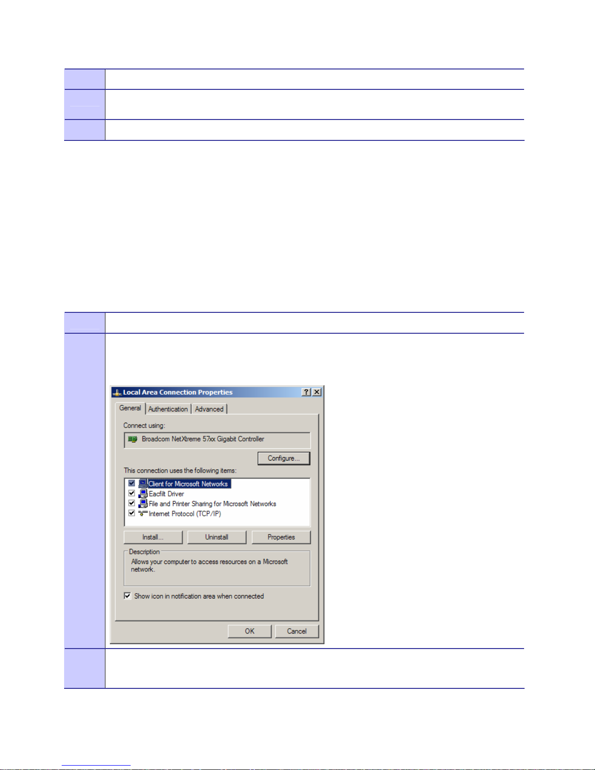
Figure A-8 Local Area Connection Properties Screen
Highlight Internet Protocol (TCP/IP) selection and click on the Properties button.
Figure A-9 Selecting TCP/IP from the Local Area Connection Properties Screen
6881011Y68-B October 2006
A-5
Page 54

Appendix A: Reference Information
4
Click the Use the following IP address radio button and populate the IP address field with
192.168.0.150. Populate the Subnet mask field with 255.255.255.0. Click on OK for the changes to take
affect. Close all Local Area Connection Properties windows. These steps allow the laptop to
communicate with the camera to determine IP address of the wireless interface.
Figure A-10 IP Address and Subnet Mask Settings
5
6881011Y68-B October 2006
Insert the WMC7300 wireless card into the camera’s PCMCIA slot. Reboot camera.
A-6
Page 55

MOTOMESH 1.2 Mesh Camera System Setup and Configuration Guide
6
Point a browser to the camera’s default IP address or 192.168.0.100 to verify connectivity.
Figure A-11 Sony Camera Local Web Page
7
8
At the Sony Web page, click on the Setting button area. If you are presented with a Login dialog, use
lowercase admin for both, username and password.
Click on Network, then click on Wireless, and finally click on Mesh Network.
Figure A-12 Web page Mesh Network Settings
9
6881011Y68-B October 2006
Verify that Network DHCP is selected, that DNS is set to ON, and that Authentication Control is set
A-7
Page 56

Appendix A: Reference Information
to Force Authorized.
10
11
Note down the IP address listed on the page, as you will need it for the next step.
Disconnect the cross-over Ethernet cable and point a browser to the IP address as noted above.
This will verify functionality and connectivity of the wireless link
12
End of Procedure.
6881011Y68-B October 2006
A-8
Page 57

Index
Index
.............................................
.
.
.
.
IP address field, 2-4
A
IP Addressing, 2-9, 2-10, 2-13, 2-14, 2-17
antenna, 1-16
Authentication Control, A-7
Authentication control field, 2-7, 2-11, 2-16
B
Bracket, 1-4, 1-12
C
Camera, 1-1, 1-2, 1-3, 1-4, 1-6, 1-7, 1-10, 1-13, 1-16, 2-1,
2-5, 2-8, 2-12, 2-16, 2-17, A-1
Copyrights, iii
cross-over Ethernet cable, 2-1, A-5, A-8
D
DHCP, 2-7, 2-10, 2-11, 2-14, 2-16, 2-17
DHCP server, 3-4
Disclaimer, iii
DNS, 2-7, 2-11, 2-16, A-7
Dome, 1-1, 1-4, 1-8, 1-10, 1-13
E
Ethernet cable, 2-1
L
laptop, 2-1, A-5, A-6
Laptop, 1-10, 2-1
Lease time, 2-17
Local Area Connection, 2-1, 2-4
M
MEA drivers, 3-5
N
Network DHCP, 2-7, 2-10, 2-11, 2-14, 2-16, A-7
O
OTA (Over the Air), A-1
P
PCMCIA slot, 2-4
PCMCIA slot location, 1-6
Peer-to-Peer, A-5
PELCO, 1-4, 1-10, 1-11, 1-14
power supply, 1-10, 1-11, 1-12, 1-14
F
firmware, A-1
Force Authorized, A-7
G
gooseneck, 1-10, 1-12, 1-13
I
IP address, 2-4, 2-5, 2-10, 2-16, 2-17
6881011Y68-B October 2006
Index
R
RealShot, 1-2, 1-4, 2-1, 2-7, 2-16
S
Sony SNC-RX550 Firmware Upgrade Tool screen, A-1
static address, 2-17
Subnet mask, 2-4
-1
Page 58

Index
T
TCP/IP, 2-2
TCP/IP Properties, 2-4
Trademarks, iii
V
Verifying Connectivity, 2-5
W
wireless card, 2-4, 2-6, 2-10, 2-15
WMC6300, 2-4, A-1
WMC7300, 1-1, 1-5, 2-4, 2-17, A-1
6881011Y68-B October 2006
Index
-2
Page 59

Glossary
.............................................
.
.
.
IAP – Intelligent Access Point
MEA – Mesh Enabled Architecture also referred to as WMB
MiSC – Mobile Internet Switching Controller
PTZ – Pan/Tilt/Zoom (feature and motor on Sony Camera)
Glossary
WMB – Wireless Mobile Broadband also referred to as MEA
WMC – Motorola Wireless Modem Card, can apply to WMC6300 or WMC7300 model
number
WR – Wireless Router
6881011Y68-B October 2006
Glossary-1
Page 60

Glossary
This page intentionally left blank.
6881011Y68-B October 2006
Glossary-2
 Loading...