

MOTOROLA MMBD452LT1 Datasheet
MOTOROLA
SEMICONDUCTOR TECHNICAL DATA
Order this document
by MMBD452LT1/D
Dual Hot-Carrier Diodes
Schottky Barrier Diodes
These devices are designed primarily for high–efficiency UHF and VHF detector
applications. They are readily adaptable to many other fast switching RF and digital
applications. They are supplied in an inexpensive plastic package for low–cost,
high–volume consumer and industrial/commercial requirements.
• Extremely Low Minority Carrier Lifetime
• Very Low Capacitance
• Low Reverse Leakage
MAXIMUM RATINGS
Rating
Reverse Voltage V
Forward Power Dissipation
@ TA = 25°C
Derate above 25°C
Operating Junction
T emperature Range
Storage Temperature Range T
DEVICE MARKING
MMBD452LT1 = 5N
ELECTRICAL CHARACTERISTICS (T
Reverse Breakdown Voltage (IR = 10 µA) V
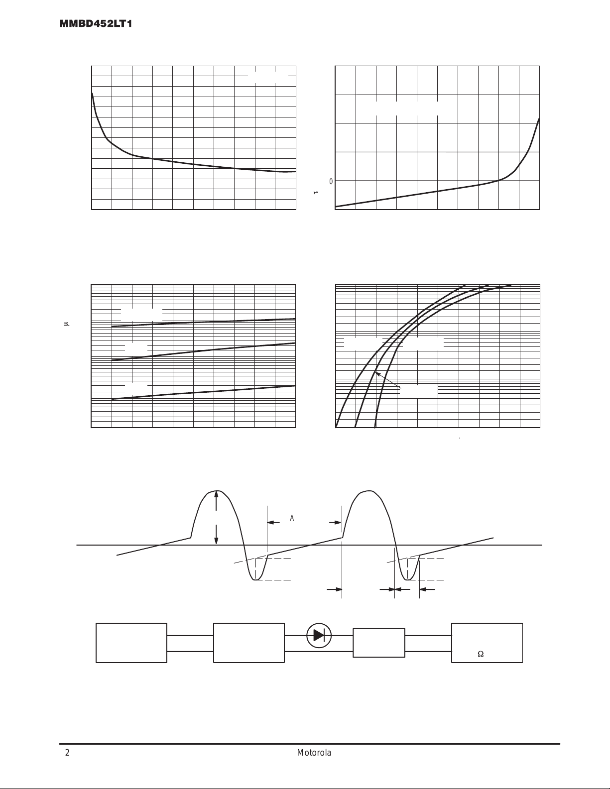
Total Capacitance (VR = 15 V, f = 1.0 MHz) Figure 1 C
Reverse Leakage (VR = 25 V) Figure 3 I
Forward Voltage (IF = 1.0 mAdc) Figure 4 V
Forward Voltage (IF = 10 mAdc) Figure 4 V
(TJ = 125°C unless otherwise noted)
Symbol Value Unit
R
P
F
T
J
stg
= 25°C unless otherwise noted) (EACH DIODE)
A
Characteristic
30 Volts
225
1.8
–55 to +125
–55 to +150 °C
mW
mW/°C
°C
Symbol Min Typ Max Unit
(BR)R
T
R
F
F
MMBD452LT1
Motorola Preferred Devices
30 VOLTS
DUAL HOT–CARRIER
DETECTOR AND SWITCHING
CASE 318–08, STYLE 11
ANODE
30 — — Volts
— 0.9 1.5 pF
— 13 200 nAdc
— 0.38 0.45 Vdc
— 0.52 0.6 Vdc
DIODES
3
1
2
SOT–23 (TO–236AB)
1
3
CATHODE/ANODE
2
CATHODE
Preferred devices are Motorola recommended choices for future use and best overall value.
Thermal Clad is a registered trademark of the Berquist Company .
Motorola Small–Signal Transistors, FETs and Diodes Device Data
Motorola, Inc. 1997
1
MMBD452LT1
TYPICAL ELECTRICAL CHARACTERISTICS
2.8
2.4
2.0
1.6
1.2
0.8
, TOTAL CAPACITANCE (pF)C
T
0.4
0
0 3.0 6.0 9.0 12 15 21
VR, REVERSE VOLTAGE (VOLTS)
Figure 1. T otal Capacitance
10
1.0
m
0.1
TA = 100°C
75°C
f = 1.0 MHz
500
400
300
200
100
, MINORITY CARRIER LIFETIME (ps)
t
3024 2718
0
100
10
KRAKAUER METHOD
01020
30 40 50 60 70 80 10090
IF, FORWARD CURRENT (mA)
Figure 2. Minority Carrier Lifetime
TA = 85°C
TA = –40°C
0.01
, REVERSE LEAKAGE ( A)I
R
0.001
0 6.0 12 18 24
25°C
VR, REVERSE VOLTAGE (VOLTS)
Figure 3. Reverse Leakage
I
F(PEAK)
SINUSOIDAL
GENERATOR
BALLAST
NETWORK
(PADS)
30
CAPACITIVE
CONDUCTION
I
R(PEAK)
FORWARD
CONDUCTION
1.0
, FORWARD CURRENT (mA)I
F
0.1
0.2 0.4 0.6 0.8 1.0 1.2
TA = 25°C
VF, FORWARD VOLTAGE (VOLTS)
Figure 4. Forward Voltage
STORAGE
CONDUCTION
PADS
DUT
SAMPLING
OSCILLOSCOPE
(50 W INPUT)
Figure 5. Krakauer Method of Measuring Lifetime
2
Motorola Small–Signal Transistors, FETs and Diodes Device Data
 Loading...