

Motorola MMAS40GWB Datasheet
SEMICONDUCTOR TECHNICAL DATA
±40g Amplified
The MMAS40G family of silicon capacitive, micro–machined accelerometers
features integral signal amplification, signal conditioning, a 4–pole low–pass
filter and temperature compensation. Zero–G offset, full scale span and filter
roll–off are factory set and require no external passives. A calibrated self–test
feature mechanically displaces the seismic mass with the application of a digital
self–test signal.
The MMAS40G incorporates a single polysilicon seismic mass, suspended
between two fixed polysilicon plates (G–cell). The forces of acceleration move
the seismic mass, thereby resulting in a change in capacitance. The G–cell is
sealed at the wafer level, creating a particle–free environment. The G–cell
features built–in damping and over–range stops to protect it from mechanical
shock.
MMAS40G accelerometers are ideally suited for automotive crash detection
and recording, vibration monitoring, automotive suspension control, appliance
control systems, etc.
Features
• Minimum Full Scale Measurement ±40g
• Calibrated, True Self–Test
• Senses Parallel to the Printed Circuit Board
• Integral Signal Conditioning and 4–Pole Filter
• Linear Output
• Robust, High Shock Survivability
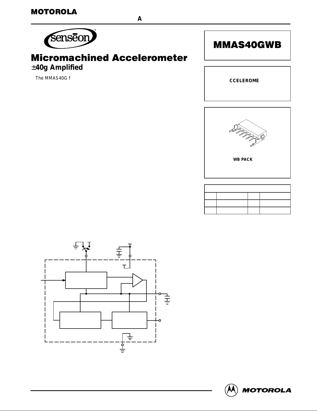
SIMPLIFIED BLOCK DIAGRAM
+
+
Order this document
by MMAS40GWB/D
MICROMACHINED
ACCELEROMETER
±40g AMPLIFIED
(Wingback)
1
2
3
4
5
6
WB PACKAGE
CASE 456–03
PIN NUMBER (WB)
1 4
NC (1) V
25
Self–Test GND
36
Output VS (2)
NOTES:
1. Connect to ground.
2. Bypass at pin to ground with 0.1 µF
ceramic capacitor for specified performance.
ref
(2)
2 SELF–TEST
g
(Replaces XMMAS40GWB)
Motorola Sensor Device Data
Motorola, Inc. 1997
G–CELL
LOW–PASS FILTER
6V
S
+
A
TEMPERATURE
COMPENSATION
5 GND
4V
ref
3
OUTPUT
1
MMAS40GWB
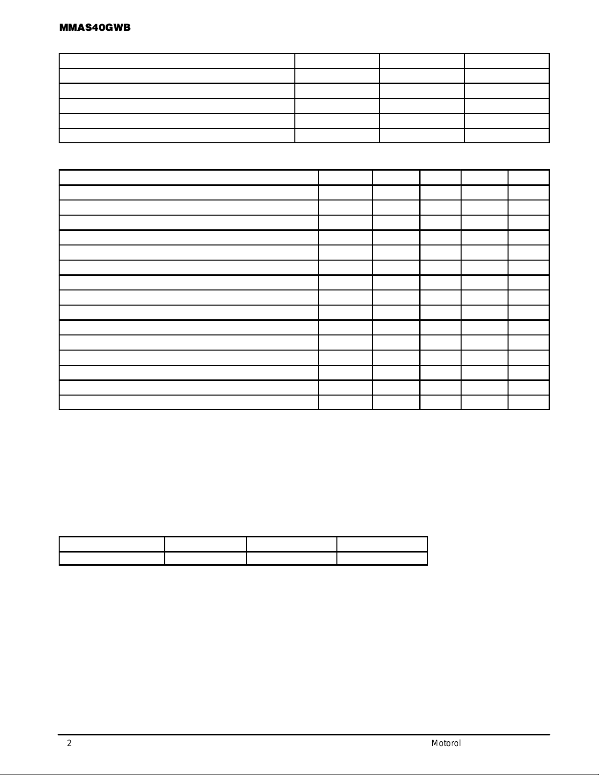
MAXIMUM RATINGS
Rating Symbol Value Unit
Acceleration (biased each axis) G ±500 g
Acceleration (unbiased each axis) G ±2000 g
Supply Voltage V
Storage Temperature T
Operating Temperature(6) T
Smax
stg
A
–0.3 to +7.0 Vdc
–40 to +105 °C
–40 to +85 °C
OPERATING CHARACTERISTICS (V
Characteristic Symbol Min Typ Max Unit
Acceleration Range G ±40 ±55 — g
Output Drive Capability — –0.2 — 0.2 mA
Supply Voltage V
Supply Current I
Full Scale Output Range V
Sensitivity (over temperature range) (2) (3) ∆V/∆G 36 40 44 mV/g
Zero Acceleration Output (over temperature range) (3) (4) V
Linearity — — 0.5 2.0 %FSO
Transverse Sensitivity — — 1.0 3.0 %FSO
Frequency Bandwidth — 300 400 500 Hz
Noise — — 15 25 mV
Self–Test Output Equivalent (5) G
Self–Test Input Low V
Self–Test Input High V
Self–Test Input Current — 10 70 200 µA
NOTES:
1. The output voltage increases from the Zero Acceleration Output for positive acceleration and decreases for negative acceleration. The
typical sensitivity is 40 mV/g. For example, with VS = 5.0 V , a +20g input will result in a 3.3 V output. (V
input will result in a 1.7 V output.
2. Sensitivity is a ratiometric parameter: ∆V/∆G
3. The compensated temperature operating range is –40 to +85°C.
4. Zero Acceleration Output is a ratiometric parameter: V
5. Equivalent output in response to a Logic Level One on the self–test pin.
6. Additional temperature range available. Consult factory.
= 5.0 Vdc, TA = 25°C unless otherwise noted)
S
S
O
FSO
off
S
STL
STH
(Vs)
= ∆V/∆G
off(Vs)
x (VS/5 V).
(5 V)
= V
off(5 V)
x (VS/5 V).
4.75 5.0 5.25 V
— 5.0 7.0 mA
0.3 — VS – 0.3 V
2.2 2.5 2.8 V
20 25 30 g
— — 1.6 V
3.4 — — V
= 2.5 + 0.040 x 20) and a –20g
output
pk
ORDERING INFORMATION
Device Temperature Range Case No. Package
MMAS40GWB –40 to +85°C 456–03 Plastic Wingback
2
Motorola Sensor Device Data
 Loading...