

Page 1
User Manual
16x4 Cable Modem
plus
AC1600 Wireless
Router
MG7540
Page 2

NOTICE
This document contains proprietary information protected by copyright, and this Manual and all
the accompanying hardware, software, and documentation are copyrighted. No part of this
document may be photocopied or reproduced by mechanical, electronic, or other means in any
form.
The manufacturer does not warrant that the hardware will work properly in all environments and
applications, and makes no warranty or representation, either expressed or implied, with respect
to the quality, performance, merchantability, or fitness for a particular purpose of the software or
documentation. The manufacturer reserves the right to make changes to the hardware, software,
and documentation without obligation to notify any person or organization of the revision or
change.
All brand and product names are the trademarks of their respective owners.
© Copyright 2016 MTRLC LLC
All rights reserved.
SAFETY
This equipment is designed with the utmost care for the safety of those who install and use it.
However, special attention must be paid to the dangers of electric shock and static electricity when
working with electrical equipment. All guidelines of this and of the computer manufacture must
therefore be allowed at all times to ensure the safe use of the equipment.
CAUTION:
Do not put the cable modem in water.
Do not use the cable modem outdoors.
Keep the cable modem in an environment that is between 0°C and 40°C (between 32°F
and 104°F).
Do not place any object on top of the cable modem since this may cause overheating.
Do not place the cable modem in a confined space that may cause overheating.
Do not restrict the flow of air around the cable modem.
MOTOROLA and MTRLC assume no liability for damage caused by any improper use of the
cable modem.
Table of Contents
Introduction 4
Quick Start 4
Alternate Ways to Connect Your Coax Cable 13
Connecting Devices to Your Cable Modem/Router 14
CONNECTING A DEVICE VIA ETHERNET ................................................................................. 14
Page 3

CONNECTING A SMARTPHONE, TABLET OR OTHER WIRELESS DEVICE VIA WIRELESS ........................... 14
Setting up an HDTV, Streaming Media Device, or Other Device 16
Accessing the Configuration Manager by Using a Browser 17
Configuring Your MG7540 to Support Devices and Applications with Special
Requirements 23
FOR GAMES PLAYED ON GAME CONSOLES AND PCS, AND SECURITY CAMERAS .................................. 23
TO CREATE A PORT FORWARDING RULE ................................................................................ 26
Changing Wireless Settings 30
TO CHANGE THE NETWORK NAME AND PASSWORD ................................................................... 32
WIRELESS GUEST NETWORKS ............................................................................................ 32
Changing Firewall Settings 35
Tuning Wireless Performance 37
WI-FI MULTIMEDIA (WMM) ............................................................................................. 42
Parental Control 43
SETTING UP A BLACKLIST ................................................................................................. 45
SETTING UP A WHITELIST ................................................................................................. 47
SETTING UP TIMES WHEN INTERNET ACCESS IS ALLOWED AND NOT ALLOWED .................................. 49
Changing Your MG7540’s Username and Password, and Resetting to Factory
Defaults 56
CHANGING YOUR MG7540’S USERNAME AND PASSWORD .......................................................... 56
RESETTING TO FACTORY DEFAULTS ...................................................................................... 57
Configuring Alternate Wi-Fi Security Settings 58
ALTERNATIVES TO WPA2--WPA, WEP, AND RADIUS .............................................................. 58
Troubleshooting Tips 61
WHAT IF I CAN’T MAKE AN INTERNET CONNECTION RIGHT AFTER INSTALLATION? ............................... 61
WHAT IF MY MG7540 HAS BEEN WORKING THEN STOPS WORKING? .............................................. 61
WHAT IF I’M GETTING INTERNET SERVICE BUT MY SPEED IS DISAPPOINTING? ................................... 62
WHAT IF I'M TOLD THAT MY MG7540 ISN'T APPROVED BY MY CABLE SERVICE PROVIDER? .................... 62
WHAT IF I AM CONNECTED WIRELESSLY BUT MY CONNECTION SEEMS SLOW OR KEEPS DROPPING? ........... 62
WHAT IF I DON’T KNOW MY MG7540’S WIRELESS NETWORK NAMES/SSIDS OR SECURITY KEY/PASSWORD?
................................................................................................................................ 63
WHAT IF I THINK THAT WIRELESS DEVICES ARE INTERFERING WITH MY MG7540 WIRELESS ROUTER? ...... 63
Support 64
WE LIKE TO HELP. .......................................................................................................... 64
LIMITED WARRANTY ....................................................................................................... 64
Compliance 65
Page 4

Introduction
The Motorola Model MG7540 is a 16x4 DOCSIS 3.0 cable modem with a built-in
AC1600 Wi-Fi router that has 4 Gigabit Ethernet ports. This model connects to
standard cable company Internet service. Model MG7540 can provide shared
Internet access to Ethernet-capable and Wi-Fi devices including computers,
smartphones, tablets, HDTVs, game consoles, security cameras, and streaming
media devices. The MG7540 is a dual-band Wi-Fi router, and supports clients that
operate on both the 2.4 and 5 GHz bands.
Basic Installation instructions for Model MG7540 are in the Quick Start that comes
with Model MG7540 and that is duplicated in Chapter 2 of this User Guide.
Model MG7540 has a Configuration Manager that provides a lot of technical
information about Model MG7540 and that tells you how to do some useful things
as summarized below. Please note that some users will never need to use the
Configuration Manager.
Chapter 3: Alternate Ways to Connect Your Coax Cable
Chapter 4: Connecting Devices to Your Cable Modem/Router
Chapter 5: Setting up an HDTV, Streaming Media Device, or Other Device
Chapter 6: Accessing the Configuration Manager by Using a Browser
Chapter 7: Configuring Your MG7540 to Support Devices and Applications with
Special Requirements, like Games Played on Game Consoles and PCs, and
Security Cameras
Chapter 8: Changing Wireless Settings
Chapter 9: Changing Firewall Settings
Chapter 10: Tuning Wireless Performance
Chapter 11: Parental Control
Chapter 12: Troubleshooting Tips
Quick Start
Page 5
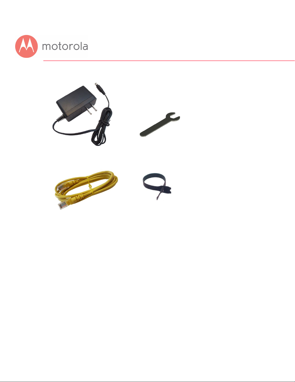
Packaged with your MG7540 modem/router
Power Cube Coax Wrench
Ethernet Cable Velcro® Cable Tie
Page 6

-
Let’s get started
If you don’t have cable Internet service, please order that from your cable service
provider.
Now connect your MG7540 as shown on the next panel.
Connecting to a Coax Cable
Soon you’ll need to connect your MG7540 to a
“live” coax cable. Sometimes a cable will already
be available. Sometimes there’s a coax wall jack
available, and you connect to the jack with a coax
cable. Your MG7540 can also share a coax cable
attached to a TV by using a coax splitter.
Page 7
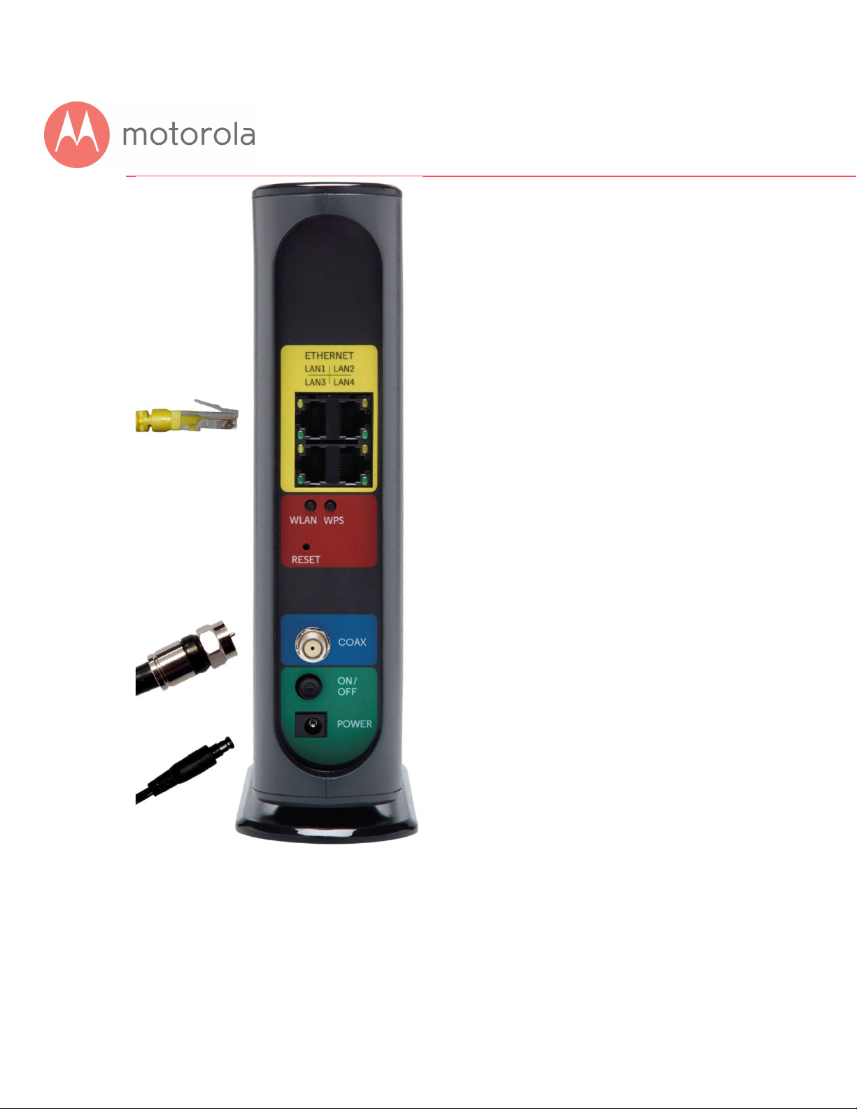
ETHERNET (LAN 1-4)
You can connect a computer, HDTV,
game station, or other
Ethernet-capable device to any of
these 4 LAN ports.
WLAN button
Wi-Fi on/off button
WPS button
RESET
COAX
Connect a “live” coax cable to the
modem’s COAX connector as
discussed above.
(Tighten the nut
so it’s finger tight. You may want to
use the supplied wrench. Make the
connection snug but not
over-tight.)
ON/OFF button
POWER
Connect the supplied power cube
between the power jack and an
electrical outlet.
Prepare to activate
By now you should have:
Page 8
Subscribed to cable Internet service.
Connected your MG7540.
Powered up your MG7540. To do this, the On/Off button needs to be On. Wait for
the green online connection light to stop flashing and remain solidly lit. This
may take up to 15 minutes.
You should have a recent cable bill handy because it has your account number and
you’ll probably need that.
If you’re asked for information about the MG7540, you can find this on the label on
the bottom of the MG7540.
Activate
For some service providers, you activate by calling them. Many service providers
including Comcast and Cox prefer that you activate by opening the Web browser
of a computer that’s plugged into one of the MG7540’s Ethernet ports.
If you don’t have a computer, you can use the Web browser of a Wi-Fi device such
as a smartphone or tablet. In that case you’ll need the unique Wireless Network
Names (SSIDs) and Password printed on the bottom of your MG7540. Note that
your MG7540 supports two Wi-Fi bands, and there are separate SSIDs for these
bands. The bands are 2.4 and 5 GHz. Both bands use the same Password by
default. You’ll use these in setting up your wireless device to connect to the
MG7540. Once you’ve connected, you can open the browser of that wireless
device.
Page 9

Time Warner
For Comcast XFINITY Users Only
:
If the activation page does not appear, please go to
www.xfinity.com/internetsetup for more information and to activate your
modem.
Here is a list of phone numbers for some major cable service
providers
. (Note that this list is subject to change.)
Comcast 1 (855) 652-3446
1 (855) 704 4503
Bright House 1 (888) 289-8988
Suddenlink 1 (877) 794-2724
Cable One 1 (877) 692 2253
Cox 1 (888) 556-1193
RCN 1 (866) 832-4726
Once your MG7540 is activated either online or by phone, your
service provider will provision your MG7540 service. Typically this
takes less than 5 minutes, but in some cases this may take 30
minutes or longer to complete.
Try to browse the Web using a device connected via Ethernet or Wi-Fi to the
MG7540. If browsing works, Congratulations! Your MG7540 is working.
If your MG7540 is NOT working, see Troubleshooting Tips below.
Page 10

Configuration Manager
Most MG7540 users never use the Configuration Manager. Here are some reasons
for using the Configuration Manager:
You want to change the wireless router setup. For instance, maybe you’re
replacing a router and want to use your existing Wireless Network Name(s) and/or
Password(s) instead of the unique ones that come with the MG7540.
You want to set up special Internet gaming settings.
You want to set up parental controls including white lists and/or black lists for
certain users and times.
You want to get performance information about the MG7540 modem and/or
built-in router. This can be helpful in optimizing wireless performance.
If you need to access the MG7540 Configuration Manager, open your Web
browser. Type http://192.168.0.1 in the address bar and press the Enter key.
In the login dialog box, type the following User Name and Password in lower case,
then click OK.
User Name: admin
Password: motorola
The status page will appear. If the Status page doesn’t appear, please see the
Troubleshooting Tips below.
For details about the Configuration Manager, please see Chapter 6 in this
manual.
Page 11

Wireless Router
As noted before, the MG7540 has unique Wireless Network Names/SSIDs and a
unique WPA/WPA2 Wireless Security Key/Password printed on the MG7540’s
bottom label. If you don’t change these, you should set up your wireless devices to
work with these SSIDs and security key.
Note that wireless performance depends on a number of factors. Please keep
these things in mind:
Where possible, put the MG7540 in a central place so that it’s not too far away
from your other wireless devices.
Try to avoid interference from other wireless devices such as Bluetooth headsets
and stereos, and 2.4 GHz and/or 5 GHz cordless phones and base stations. Don’t
put the MG7540 close to these interfering devices.
Sometimes it helps to change the MG7540 wireless channel frequencies to reduce
interference with neighbors’ wireless networks. This is discussed in the
Troubleshooting section.
Page 12
ON:
OFF:
n ON:
C
onnected
on 1 channel
Blue Blinking:
Negotiating bonded channel(s)
†
Blue ON:
Bonded with 2 or more channels
Connected on 1 downstream channel
Blue Blinking:
Negotiating bonded channel(s)
†
Blue ON:
Trying to go online
Green:
Connected at highest LAN speed, 1 Gbps
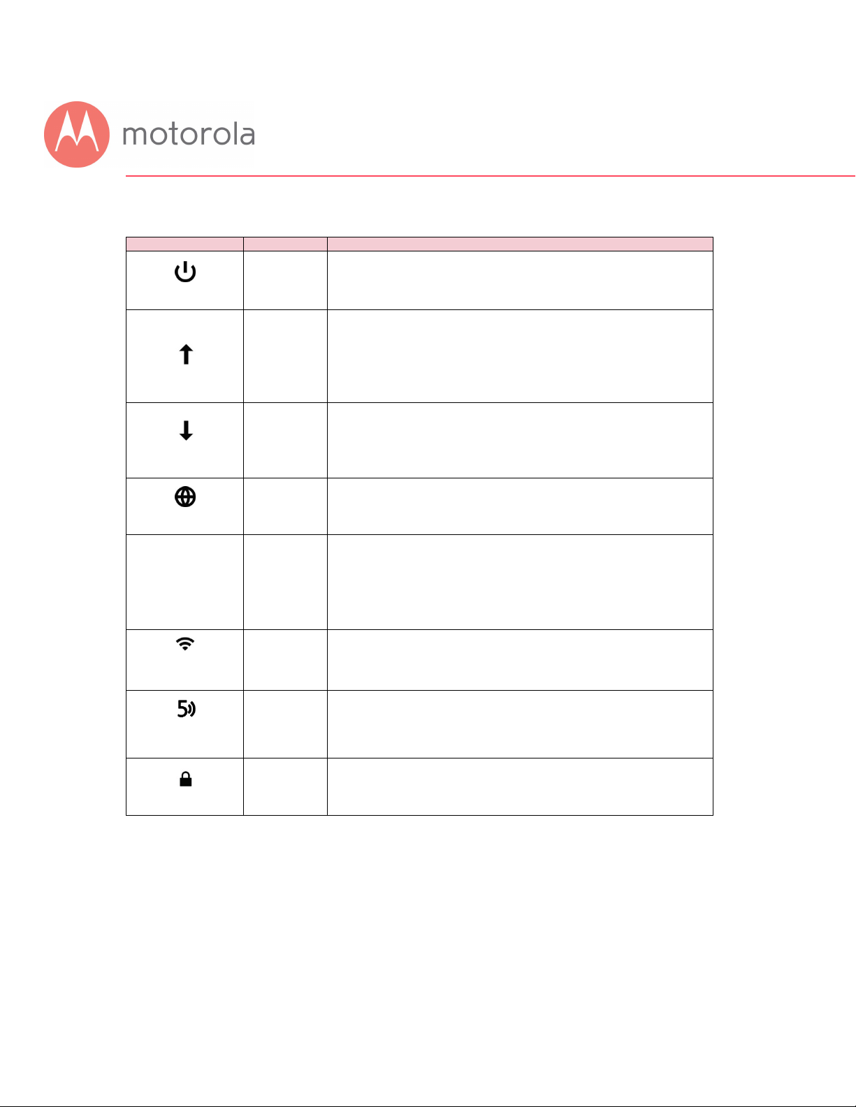
Front Panel Lights
During Power up, the lights will blink for about a minute.
LIGHT COLOR DESCRIPTION
Power
Green
MG7540 power on
MG7540 power off
Green or
Blue
Gree
Upstream
Green Blinking: Ranging in progress
OFF: Upstream not connected
Green Blinking: Scanning for DS channel
Downstream
Online
1 2
3 4
Ethernet
Green or
Blue
Green
Green
Amber
Green ON:
Bonded with 2 or more channels
Blinking:
ON: Online
OFF: Offline
Blinking: Ethernet data is flowing
or
Amber: Connected at 10 or 100 Mbps
OFF: No connection
LAN ports
2.4 GHz
WLAN
Green
Blinking: Data is flowing
ON: 2.4 GHz Wi-Fi is enabled
OFF: 2.4 GHz Wi-Fi is not enabled
Blinking: Data is flowing
5 GHz
WLAN
Green
ON: 5 GHz Wi-Fi is enabled
OFF: 5 GHz Wi-Fi is not enabled
Blinking: WPS is in discovery mode
WPS
†
If a blue light blinks continuously, this indicates partial service (at least one designated channel has not completed
bonding). You should still get high Internet speeds, but your service provider may want to know so they can adjust
their network.
Green
ON: Light will remain solid after
WPS configuration is successful
Page 13

Alternate Ways to Connect Your Coax Cable
As summarized in the Quick Start, one important connection is the coaxial cable
connection that carries your cable Internet service to your MG7540. Here are the
main ways you can make that connection:
1) Use the loose end of an available “live” coaxial cable from your cable
service provider. Plug the loose end into the Coax jack of your cable
modem.
2) If there’s a “live” coax jack in your wall, connect a coax cable between that
jack and the Coax jack of your cable modem.
3) Use a “live” cable that’s plugged into one of your televisions. If you still
want cable TV to go to that TV set, you can get a coaxial splitter and two
cables of the right length as shown below.
Page 14

Connecting Devices to Your Cable Modem/Router
You can connect computers, smartphones, tablets, game consoles, security
cameras, streaming media devices (like Roku, Chromecast & AppleTV),
Internet-enabled HDTVs and other devices to your cable modem/router.
You can connect these devices either with an Ethernet cable (a wired connection),
or via Wi-Fi (a wireless connection).
An Ethernet connection is normally a faster, more reliable connection than a
wireless connection. To make an Ethernet connection, you need a device with an
Ethernet connector and a cable to connect between that device and your cable
modem. In some cases, this may be impossible because of the location of the
devices. In those cases, or if the device doesn’t have an Ethernet connector, you
will need to create a wireless connection as described below.
Connecting a Device via Ethernet
To make the connection at the Ethernet-capable device, simply plug in one end of
the Ethernet cable to an Ethernet jack on the device. At the cable modem, plug
the other end of the cable into any of the cable modem’s LAN jacks. You can
connect up to four devices by using the four LAN jacks.
Connecting a Smartphone, Tablet or Other Wireless Device
via Wireless
You will need to enter one or both of your wireless network names (SSIDs) and
Page 15

passwords into each client device that you want to connect to your network.
Typically, you should enter SSIDs and Passwords for both the 2.4 and 5 GHz bands
into client devices that support both bands. If you haven’t changed the factory
settings, you can find these on a label on the bottom of your modem’s stand. If
you have changed the network names and/or passwords, use your new values.
(See Chapter 8 if you want to change your wireless settings).
If you want to connect devices to a Guest Network, use the Network Name and
Password for that network. (See Chapter 8 if you want to set up a Guest
Network).
Wireless devices vary, but they all have a Wireless Settings area. There you should
first select the wireless network you want, namely the wireless network name or
Guest network name of the MG7540. Now enter the password for your wireless
network. Make sure to turn wireless ON on your client devices. Normally that’s all
you need to do.
Page 16

Setting up an HDTV, Streaming Media Device, or
Other Device
A typical HDTV, for instance, has an Input or Setup section. Within that section
there’s normally a Network section. In that section you may need to specify that
you have an Ethernet connection if that’s how you connect to the MG7540. If you
want to connect wirelessly to the MG7540, you’ll need to select its wireless
network name and then enter its wireless password.
Page 17

Accessing the Configuration Manager by Using a
Browser
Model MG7540 has a Configuration Manager that provides a lot of technical
information about Model MG7540 and that tells you how to do some useful things.
Please note that some users will never need to use the Configuration Manager.
You can access the Configuration Manager from a computer or any other device
that has a browser and that is connected via Ethernet or wirelessly to your cable
modem. If you will be changing wireless settings, it’s much better to use a device
that connects via Ethernet while you make these changes.
To access the Configuration Manager, do the following:
1) Open your browser.
2) Type 192.168.0.1 into your browser’s address bar and press Enter.
Page 18
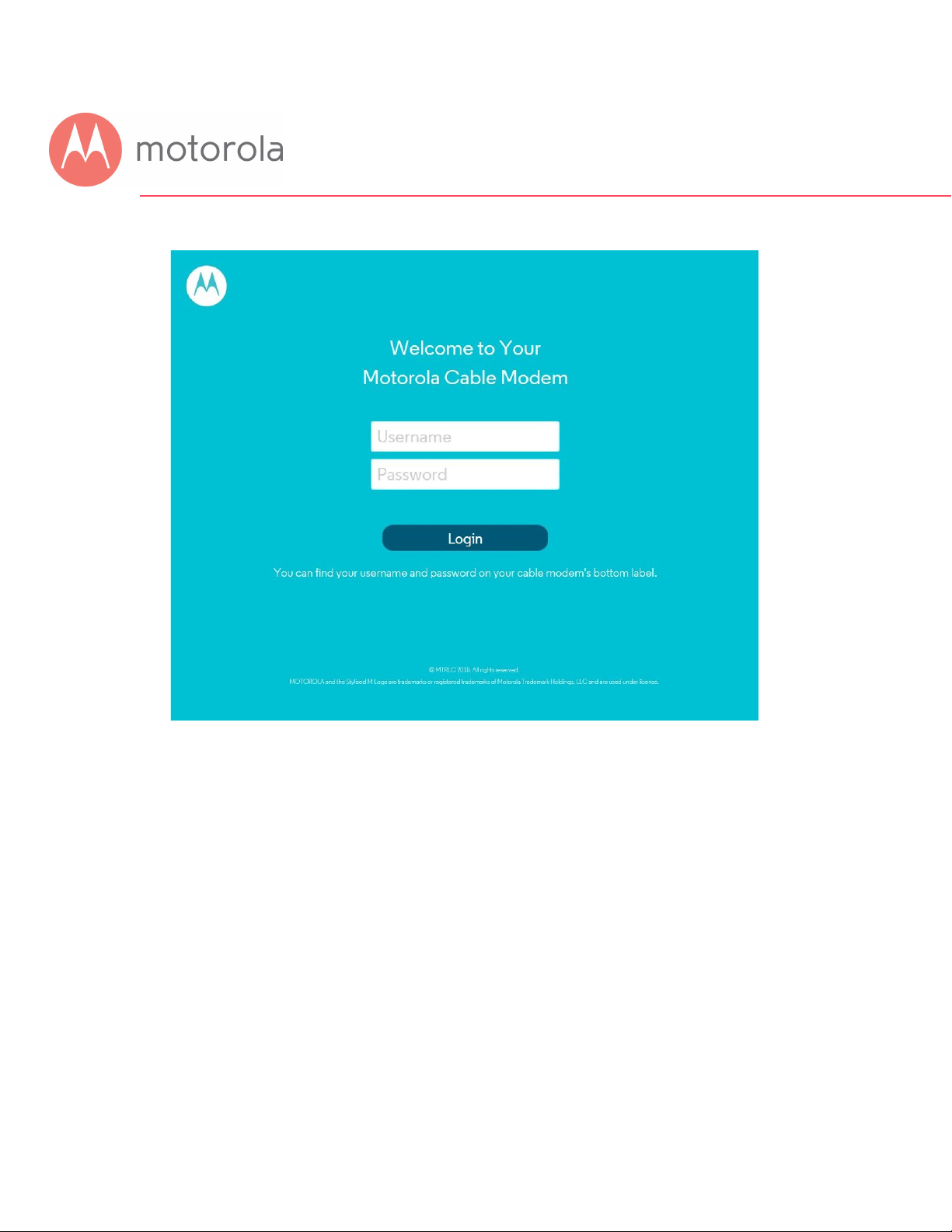
You should see this page:
3) Type admin in the Username field.
4) Type motorola in the Password field.
Page 19
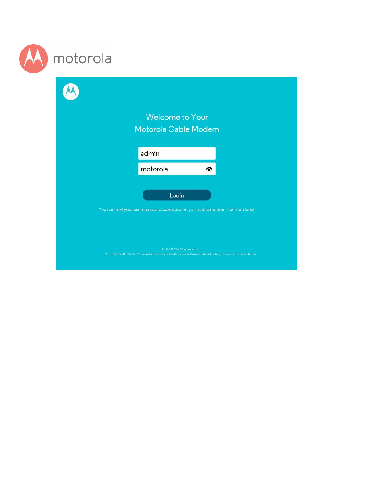
5) Click the Login button.
Page 20
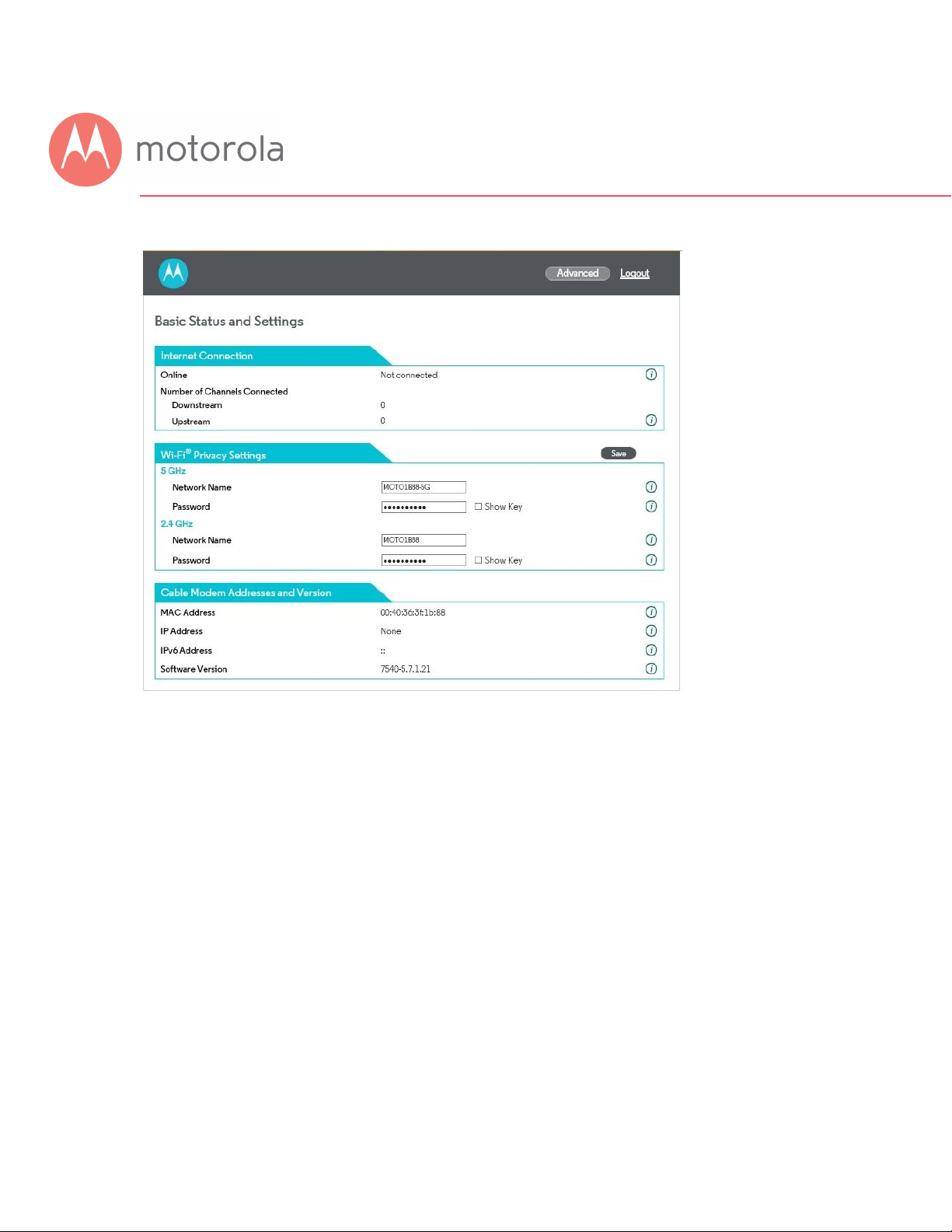
This should bring you to the Basic Status and Settings page shown below.
The Basic Status and Settings page gives you information about your Internet
connection, lets you view and modify your Wi-Fi privacy settings, and shows you
basic information about your cable modem’s addresses and software version. The
logout link lets you end your session with the Configuration Manager.
The Advanced button at the top of the page takes you to pages with more
extensive information and options to configure your cable modem/router.
Page 21

You can return to the Basic Status and Settings page from any Advanced page by
clicking the Motorola stylized M Logo in the upper left-hand corner of the page.
Note the circled (i) ‘information’ icons to the right of the page. You can click the
icons for descriptions of entries:
The information icons appear on every page, including Advanced pages.
The Advanced pages include more detailed status information, as well as
exhaustive configuration options for the Wi-Fi, Router and Firewall functions of
your device. In addition, there is a Parental Control page, and pages to set up
Virtual Private Networks (VPNs).
Click the Advanced button. Note the Menus and Submenus at the top of the page.
The currently selected menu item is highlighted (top row), and submenu items
Page 22

corresponding to the selected menu item are displayed in the second row. The
currently selected submenu item is indicated by a small white pointer underneath
it.
In this screenshot, the menu item Status and submenu item Software are
selected.
The following sections in this guide will walk you through the features that users
most often want to configure.
Page 23

Configuring Your MG7540 to Support Devices and
Applications with Special Requirements
For Games Played on Game Consoles and PCs, and
Security Cameras
Devices including game consoles and security cameras often require special
router settings to work correctly. This may also be true of games that you play on
a PC or another device. For gaming, you probably want to use special settings if
you’re playing another person or a computer over the Internet. You don’t need
special settings for games that don’t involve connecting to another player or
computer over the Internet.
Typically, you will have to open ports on your router to support these devices.
There may be other settings that you need to change.
To open ports, first log into the Configuration Manager as described in chapter 4.
In summary, you type 192.168.0.1 in the address bar of your browser, go to that
address, enter the Username admin and Password motorola, then click the
Login button.
This will bring you to the Basic Status and Settings page. Click the Advanced
button in the upper right. This will bring you to the Status Software page.
Hover over the Advanced Router menu item, and select the Forwarding submenu:
Page 24

You can create forwarding rules for both IPv4 and IPv6 environments. These rules
determine how data flows from the address to specified LAN addresses and ports.
In this document we will describe how to create a rule for an IPv4 network. The
steps are similar for IPv6.
To create an IPv4 Forwarding Rule, first click the Add_IPv4 button. You can now
enter your port forwarding information.
Page 25

Review your game or device documentation to find the port or ports that need to
be forwarded. Also, determine the IP Address that your device is using. You game
or device documentation should show you where to find this.
Your game or device may need more than one port to be forwarded. In some
cases, the ports will be numbered sequentially, in a range. In other cases, the
ports may be separated. In this case, you will have to set up a separate
forwarding rule for each port.
Page 26

To Create a Port Forwarding Rule
1 Under Local IP Address, enter the address of the game station, PC
or other device. In the case of a security camera, enter the address
of the camera’s DVR.
2 Under Local Start Port, enter the starting port that your device or
game needs.
3 Under Local End Port, if your device uses a sequential range of port
numbers, enter the highest number in the range. Otherwise, if there
is only one number, enter the start port number again.
4 Unless instructed otherwise in your game or device documentation,
leave the External entries blank. They will fill in automatically.
5 Select the protocol, TCP, UDP or Both, indicated in your
documentation.
6 Select Enable in the Enable/Disable pulldown.
7 Click Save.
Repeat these steps as necessary to create rules for multiple ports or port ranges.
The rule or rules you create will appear at the bottom of the page, as shown below.
Note that you can clear individual rules, or all rules.
Page 27

For games and game consoles, you may also need to enable UPnP and to set the
Firewall to OFF.
Page 28

Click the UPnP Enable box, and click Save at the top of the Router Selections box.
Page 29

Select Off in the IPv4 Firewall Protection pulldown, and click Save.
Page 30

Changing Wireless Settings
The MG7540 comes set up for wireless-N (2.4 GHz band) and wireless-AC (5 GHz
band) with WPA2 security, with unique wireless network names (SSIDs) for each
band, and a unique password. Both bands use this password. There’s a good
chance that you’ll want to use these settings. In that case you will need to
configure client wireless devices (laptops, smartphones, etc.) with your MG7540’s
wireless network names and password to connect the devices to the Primary
Network on your MG7540. (You may want to enable a separate Guest Network or
Networks for visitors and others for whom you want to provide Internet access
without also providing access to your computers and other devices connected to
your network.)
You may want to change the wireless settings on the Primary Network. The most
common reason is that you’re replacing a cable modem/router and you want to
use the same wireless network names and passwords that you’ve had. If you
change the wireless settings on your MG7540 to match your previous settings,
you won’t have to change the settings of wireless devices that worked with your
previous router. Unless there’s a good reason to change your wireless settings,
you should use the unique ones assigned at the factory.
To change the wireless settings, first log into the Configuration Manager as
described in chapter 6. In summary, you type 192.168.0.1 in the address bar of
your browser, go to that address, enter the Username admin and Password
motorola, then click the Login button.
Page 31

This will bring you to the Basic Status and Settings page:
Page 32

To Change the Network Name and Password
For the 5 GHz band:
1 Select and delete the old Network Name, then type in the new Network
Name.
2 Click the Save button.
3 You can click the Show Key box to check your typing for Password.
4 Select and delete the old Password, then type in the new Password.
5 Click the Save button.
For the 2.4 GHz band:
6 Select and delete the old Network Name, then type in the new Network
Name.
7 Click the Save button.
8 You can click the Show Key box to check your typing for Password.
9 Select and delete the old Password, then type in the new Password.
10 Click the Save button.
Network Name can be from 6 - 32 characters long. You can use the upper and lower
case letters (a – z and A – Z), numbers (0 - 9) and special characters (e.g. $_/& etc.)
except the single quote ‘ .
Password can be from 8 - 63 characters long. You can use upper and lower case
letters (a – z and A – Z), numbers (0 - 9) and special characters (e.g. $_/& etc.) except
the single quote ‘ .
Be sure to write down and save the new wireless network names and passwords
in a place where you can easily find it. One approach is to write them on a small
piece of paper and tape it on the bottom of your cable modem. Some people like
to take a picture of the settings with their phone, which is fine as long as long as
they save it in a place where they are sure to find it when they need it.
Wireless Guest Networks
Page 33

You can enable one or more Guest Networks to let friends use your Internet
connection without giving them access to other devices on your network.
To set up a Guest Network, first log into the Configuration Manager as described
in chapter 4. In summary, you type 192.168.0.1 in the address bar of your
browser, go to that address, enter the Username admin and Password motorola,
then click the Login button.
This will bring you to the Basic Status and Settings page. Click the Advanced
button in the upper right. This will bring you to the Status Software page.
Hover over the Wireless menu item, and select the Guest submenu:
Page 34

To configure and enable a Guest Network on the 2.4 GHz band, first select the 2.4
GHz tab, and then:
1 Select the desired Guest Network (there are seven available).
2 Click the Save button.
3 Select Enabled and click Save to enable the selected Guest Network.
The following steps are optional. Follow them if you want to change the default
Guest Network Name and Password:
4 Select and delete the old Guest Network Name, then type in the new
Guest Network Name and click Save.
5 You can click the Show Key box to check your typing for Password.
6 Select and delete the old Password, then type in the new Password.
7 Click the Save button.
To configure and enable a Guest Network on the 5 GHz band, first select the 5
GHz tab, and then repeat the steps above.
Network Name can be from 6 - 32 characters long. You can use the upper and lower
Page 35

case letters (a – z and A – Z), numbers (0 - 9) and special characters (e.g. $_/& etc.)
except the single quote ‘ .
Password can be from 8 - 63 characters long. You can use upper and lower case
letters (a – z and A – Z), numbers (0 - 9) and special characters (e.g. $_/& etc.) except
the single quote ‘ .
Changing Firewall Settings
A Firewall helps protect your Model MG7540 and the devices attached to it from
harm from outsiders connecting via the Internet. Model MG7540 comes with
reasonable firewall settings. The firewall allows all normal traffic to pass, but
protects against well-known attacks. Normally you just leave the firewall settings
in place. If you want to change them, you go to the ProtectionFirewall section of
the Configuration Manager. First log into the Configuration Manager as described
in chapter 6. In summary, you type 192.168.0.1 in the address bar of your
browser, go to that address, enter the Username admin and Password motorola,
then click the Login button.
This will bring you to the Basic Status and Settings page. Click the Advanced
button in the upper right. This will bring you to the Status Software page.
Hover over the Protection & Parental Control menu item, and select the Firewall
submenu.
Page 36

The firewall lets you set your protection level through IPv4 Firewall Protection, for
example. By default, with the Low setting, all services are allowed. If you select
Medium or High protection, the firewall will block all services except those listed in
the List of Allowed Services at the bottom of the page. Select the desired
protection level, and click Save.
The higher protection levels will make it harder for attackers to penetrate your
network. You may find that if you select one of these levels, that some Internet
activities may fail. If that is the case, you may need to use a lower level of
protection during those activities.
Note that in order to play some games, you may need to turn protection off.
When enabled, Port Scan Detection and IP Flood Detection will generate reports
in the Firewall Log if they detect their respective attacks.
Page 37

Tuning Wireless Performance
This chapter discusses steps to tune wireless performance. These steps can
optimize wireless performance in many cases.
First, note that placement of your MG7540 can be very important. Make sure it is
not too close to other wireless devices like Bluetooth transmitters (e.g. for
headsets), or a neighbor’s wireless router. For example, in an apartment an
MG7540 could be only feet away from a neighbor’s device on the other side of a
shared wall.
There are also optimizations you can make by using the MG7540’s Configuration
Manager.
Log into the Configuration Manager as described in chapter 4. In summary, you
type 192.168.0.1 in the address bar of your browser, go to that address, enter
the Username admin and Password motorola, then click the Login button.
This will bring you to the Basic Status and Settings page. When the Basic Status
and Settings page comes up, click the Advanced button at the top right.
Remember that you can go back to the Basic Status and Settings page at any time
by clicking the Motorola ‘M’ logo at the upper left of the page.
To optimize wireless performance, check channel usage of neighboring devices.
This is more likely to be an issue in the 2.4 GHz band than in the 5 GHz band, but
we will show you how to check both bands. You can do this by looking at the
wireless Scan Results table.
Page 38

Select the Wireless Scan/Bridge page. Hover over the Wireless menu item to bring
the Wireless submenu options into view, then click the Scan/Bridge submenu
option. This brings you to the Wireless Scan/Bridge page:
Page 39

Select the tab for the band you want to scan, 2.4 GHz or 5 GHz. Then click the
“Scan Wireless APs” button at the bottom of the page. This will pop up the
wireless Scan Results table:
Note that as in these sample Scan Results, you may need to scroll down to see all
neighboring networks.
For the 2.4 GHz band:
Look at the Channel column. This shows the channels that your neighboring
networks use. Available channels are 1 through 11. Many installations use only
channels 1, 6 or 11, because ideally wireless devices should be separated by 5
channels.
If there are very few neighboring wireless devices in your location, you should
Page 40

follow the rule of choosing a channel separated by 5 from all other channels. For
example, if there are two neighboring networks using channels 6 and 11, you
should choose channel 1.
If there are many neighboring networks, you may find that most use channels 1, 6
and 11. In that case, you may find you achieve better performance by choosing an
unused channel between the most-used channels, for example one of channels 3,
4, 8 or 9. You may need to experiment to find the best channel. Note good
candidate channels to use for your network. Then, navigate to the Wireless Basic
page.
For the 5 GHz band:
Look at the Channel column. This shows the channels that your neighboring
networks use. Available channels include 36 – 48 and 149 – 165. Some channels
from 52 – 144 may also be available; however, these channels may be allocated to
uses including weather RADAR and other government sanctioned applications.
As of this writing (spring of 2016) it is unusual for the 5 GHz band to be crowded.
If it is crowded in your location, choose a channel or channels that are unused or
little used by neighbors. Then, navigate to the Wireless Basic page.
Hover over the Wireless menu item to bring the Wireless submenu options into
view, then click the Basic submenu option. This brings you to the Wireless Basic
page:
Page 41

Select the tab for the band you want to change. Then select the desired channel
from the Channel pulldown, and click Save. Wait for a minute or so for client
devices to resynchronize to the new channel.
Check to see whether wireless performance has improved. If not, you can try
another channel selection.
Page 42

Wi-Fi Multimedia (WMM)
Another possible way to improve performance is to change Wi-Fi Multimedia
(WMM) settings. From the Wireless menu, click the WMM submenu:
WMM is designed to provide Quality of Service (QoS) support for traffic on your
network. In some environments, this may result in suboptimal wireless
performance. You can turn WMM Off and see if that improves performance in your
network. Select the tab for the band you are experiencing suboptimal performance
with. Then select Off and click Save.
Power Save Support is designed to support client devices with the Power Save
feature. The Power Save feature extends battery life by reducing power
consumption. However, sometimes this feature results in suboptimal wireless
performance. You can turn Power Save Support Off and see if that improves
performance in your network. Select the tab for the band you are experiencing
suboptimal performance with. Then select Off and click Save.
Page 43

Parental Control
Parental Control lets you limit access to the Internet from particular devices on
your network. For a device like a child’s computer or tablet, you can create lists of
websites that the device is allowed to visit, blocking all others (whitelists).
Alternatively, you can create lists of websites that the device may not visit,
allowing all others (blacklists). You can also set times where Internet access is
allowed and not allowed.
To make Parental Control settings, go to the Protection Parental Control section
of the Configuration Manager. First log into the Configuration Manager as
described in chapter 6. In summary, you type 192.168.0.1 in the address bar of
your browser, go to that address, enter the Username admin and Password
motorola, then click the Login button.
This will bring you to the Basic Status and Settings page. Click the Advanced
button in the upper right. This will bring you to the Status Software page.
Hover over the Protection & Parental Control menu item, and select the Parental
Control submenu:
Page 44

Note that Parental Control is Disabled by default. You should leave it disabled until
you have set up all desired Whitelists and Blacklists. Enable Parental Control once
the Whitelist and Blacklist settings are complete. Select Enable, and then Save.
If you need to modify the Whitelists or Blacklists, first Disable Parental Control and
Save. Then, Enable Parental Control when the changes are complete, and Save
again.
To set up either a whitelist or a blacklist, you will need to first find the MAC
Address of the device you want to control. On some devices, this may be found on
a label. On others, there may be a way to query the device to display this. Check
your user documentation for that device.
You may also find the device’s MAC Address by looking at the client list on your
MG7540. Click Basic Router DHCP and look at the MAC Addresses in the DHCP
Client List:
Page 45

You may have to do a little sleuthing to find your device’s MAC Address, for
example by turning the device off and on again to see which MAC Address is
removed and then restored to the list.
Setting up a Blacklist
Before you make any changes, make sure Parental Control at the top of the page
is Disabled, and click Save if you had to change this.
Under the tab List of Blocked Addresses (Blacklist), click the Add button to the
right. A set of fields will appear. Give your Blacklist a name, and then type in the
MAC Address of the device you want your Blacklist to apply to. Use the format
XX:YY:ZZ:WW:VV:UU.
Next, enter the URL of the first domain that you want to block, for example
BadSite.com.
If you want to the Blacklist to apply only during certain hours, enter the start and
stop times for the period you want the Blacklist to apply. If you want the Blacklist
to apply always, make sure to set the start time to 12:00 am and the end time to
11:59 pm.
Next, select which protocols the Blacklist should apply to. If you’re not sure, leave
this selection at the default setting, BOTH.
Page 46

Here is an example entry to block access to BadSite.com at all times:
Finally, make sure to check the Enable box, and click the Save button.
Click the + sign to add another site to block for this device:
Now you can add another site, for example WorseSite.com, to the Blacklist:
Remember to click Save.
Click the + sign again to add more sites if you like.
Click the Add button to configure a blacklist for another device, if you like.
Page 47

When you have completed all Blacklists, remember to Enable Parental Control at the top
of the page, and click Save.
Setting up a Whitelist
Before you make any changes, make sure Parental Control at the top of the page
is Disabled, and click Save if you had to change this.
Under the tab List of Blocked Addresses (Whitelist), click the Add button to the
right. A set of fields will appear. Give your Whitelist a name, and then type in the
MAC Address of the device you want your Whitelist to apply to. Use the format
XX:YY:ZZ:WW:VV:UU.
Next, enter the URL of the first domain that you want to allow, for example Jill
_Site_1.com.
If you want to the Whitelist to apply only during certain hours, enter the start and
stop times for the period you want the Whitelist to apply. If you want the Whitelist
to apply always, make sure to set the start time to 12:00 am and the end time to
11:59 pm.
Next, select which protocols the Whitelist should apply to. If you’re not sure, leave
this selection at the default setting, BOTH.
Finally, make sure to check the Enable box, and click the Save button.
Page 48

Here is an example entry to allow access to Jill_Site.com from 4:00 pm to 8:00
pm:
Now you can add another device, for example Joey’s PC, to the Whitelist. First
click the Add button.
Then enter the entry name, device MAC Address, site to allow, and start and end
time for the entry. In the example below, we have named the entry Joeys_PC, and
the site Joey_Safe_1.com, with active time from 10:00 am to 2:00 pm.
Remember to click Save.
Click the + sign to add another site to allow for this device:
Click the Add button to configure a Whitelist for yet another device, if you like.
Page 49

When you have completed all Whitelists, remember to Enable Parental Control at
the top of the page, and click Save.
Setting up Times when Internet Access is Allowed and Not
Allowed
Before you make any changes, make sure Parental Control at the top of the page
is Disabled, and click Save if you had to change this.
You can set up times when Internet is allowed by configuring a Whitelist entry
with a universal URL. By doing this, you can allow Internet access for a particular
device only during hours that you specify. Access will be allowed to all Internet
sites. Internet access will not be allowed to any site outside of the hours that you
specify.
Under the tab, List of Allowed Addresses (Whitelist), click the Add button to the
right. A set of fields will appear. Give your Whitelist a name, and then type in the
MAC Address of the device you want your Whitelist to apply to. Use the format
XX:YY:ZZ:WW:VV:UU.
In this case, enter . (that is, the single character ‘dot’ or ‘period’) as the URL.
Parental Control will interpret this to apply to all websites.
Page 50

Now set the start and end times of when you want to allow the device to have
Internet access. Here is an example of entries to allow Internet access in an
after-school period from 5:00 pm to 10:00 pm. We have named the sample entry
AfterSch:
Make sure to check the Enable box, and click the Save button.
Click the Add button to configure a Whitelist entry for an allowed schedule for
another device, if you like.
When you have completed all Whitelists, remember to Enable Parental Control at
the top of the page, and click Save.
Page 51

VPN (Virtual Private Network)
Virtual Private Networks (VPNs) provide protected connections across the Internet.
Some companies and other organizations provide remote access to their internal
networks via a VPN. Employees are typically provided with software that makes
the VPN connection from a computer.
When a computer provisioned for this type of VPN connection is connected behind
the MG7540, the MG7540 must pass through the VPN traffic. The MG7540 is
configured by default for VPN pass-through. (The IPsec and PPTP Pass-through
settings on the AdvancedOptions page respectively enable IPsec and PPTP VPN
pass-through. IPsec and PPTP are protocols used in different VPN
implementations. The pass-through settings for both are enabled by default).
The most common type of VPN connection that MG7540 users will encounter is
the type of VPN described above, that simply needs to pass through the MG7540.
The VPN pages support features that allow you to terminate VPN connections on
the MG7540 itself.
The MG7540 can terminate PPTP, L2TP and IPsec connections in specific
scenarios. It can act as a VPN server to terminate PPTP and L2TP connections, for
example from remote client computers. It can act as a VPN endpoint for IPsec
connections, for example from a remote office to a central office (“site-to-site”). It
cannot act as a VPN server to terminate IPsec connections from remote client
computers.
[Note that the following bullets need to be converted to the same font (Moto Sans?
Open Sans?) as the surrounding text.]
Page 52

To summarize, the MG7540 supports:
VPN Pass-through (for clients connected behind the device that need to
access for example a corporate network)
Page 53

Termination of VPN clients via PPTP & L2TP (The MG7540 can be
configured as a VPN server in a small office or similar environment. Clients
located on the Internet can connect to the small office network through
VPN tunnels terminated at the MG7540.)
Page 54

Site-to-Site VPN via IPsec (the MG7540 can be configured to create a tunnel
for all devices on the MG7540's LAN side to connect to a corporate
network).
The MG7540 will NOT support termination of client VPN connections via
IPsec.
A couple of notes about VPN options. IPsec uses encryption and provides the
strongest security. PPTP is considered to be the least secure VPN option. PPTP
connections are not required to include encryption or authentication. L2TP is
based on PPTP, and adds some level of compulsory authentication.
In the implementation of PPTP and L2TP on the MG7540, MPPE encryption is
optional. Both protocols require a login; L2TP requires a passkey for
authentication.
Page 55

There are three pages under VPN in the MG7540 configuration manager: IPsec,
L2TP/PPTP and Event Log. Use the IPsec page to set up an endpoint for a site
to site IPsec connection. Use the PPTP/L2TP page to set up a server for a set of
remote clients that connect via PPTP or L2TP. You may find the Event Log
useful to determine what has gone wrong if you have trouble setting up a VPN.
For details on how to configure a VPN on the MG7540, follow the help available
through the information icons on the configuration manager pages.
When the MG7540 is configured as a VPN endpoint, devices that connect to the
endpoint will need to know the IP Address of the MG7540. You can find this
address on the StatusConnections page. To provide the most stable VPN
connections, the MG7540’s router should be provisioned with a static IP
Address. You will need to order this from your cable service provider.
The VPN implementations on the MG7540 are best effort. They are also
Windows-centric. You will have to verify suitability for your own environment.
Page 56

Changing Your MG7540’s Username and Password,
and Resetting to Factory Defaults
Changing Your MG7540’s Username and Password
To change your MG7540’S Username and Password, first log into the
Configuration Manager as described in chapter 6. In summary, you type
192.168.0.1 in the address bar of your browser, go to that address, enter the
Username admin and Password motorola, then click the Login button.
This will bring you to the Basic Status and Settings page. Select Advanced at the
top of the screen, and then Status and Security.
You will need to enter the Current Username and Password, and then the new
Username and Password. Your new Password will have to be entered twice. Both
the Username and Password fields accept entries up to 15 characters long. Both
Username and Password may include lower- and upper-case letters (a – z, A – Z)
and numbers (0 – 9). Special characters are not allowed. Be sure to click Save to
write your changes to memory.
Page 57

Caution: Once you make this change, you will not be able to log into the modem if
you forget the new Username and Password . To recover, you will have to reset
the modem to factory defaults. When you reset the device to factory defaults, you
will lose all changes you have made to the modem.
Resetting to Factory Defaults
There may be occasions when you need to reset your cable modem/router to
factory defaults, for example if you have changed the Username and Password
and lost the new values. Note that if you reset your device to its factory defaults,
you will lose any changes you have made to settings in the device.
To reset to factory defaults:
1.) Make sure the cable modem/router is powered on.
2.) Find the reset button on the rear of the unit. It is marked WPS/RESET.
3.) Press and hold the Reset button for at least 10 seconds.
4.) The device will flash its LEDs and commence a reboot sequence.
Note that you will have to manually re-enter any required changes.
Page 58

Configuring Alternate Wi-Fi Security Settings
Alternatives to WPA2--WPA, WEP, and RADIUS
Your Cable Modem/Router comes from the factory configured for WPA2-PSK
wireless security with AES encryption. Some older clients may not support this
security mode. (For details, see About Wireless Security, below). To change the
wireless security mode, first open the page WPS_RADIUS_WEP.
To do this, first log into the Configuration Manager. In summary, you type
192.168.0.1 in the address bar of your browser, go to that address, enter the
Username admin and Password motorola, then click the Login button.
This will bring you to the Basic Status and Settings page. Click the Advanced
button in the upper right. This will bring you to the Status Software page.
Hover over the Wireless menu item, and select the WPS_RADIUS_WEP submenu:
To enable WPA-PSK, follow these steps:
1.) Under 802.11n Mode Enable/Disable, select Disable from the pulldown.
2.) Find the WPA2-PSK Security Settings tab. If WPA2-PSK is not enabled,
select Enabled from the WPA2-PSK pulldown and then click Save.
3.) Find the WPA-PSK Security Settings tab. Select Enabled from the WPA-PSK
pulldown.
4.) Click Save.
5.) Under Encryption, select AES+TKIP.
6.) Click Save.
7.) The device will now operate in mixed WPA-PSK / WPA2-PSK mode.
If you need to support WEP, follow these steps.
1.) Disable all WPA and WPA-PSK entries.
2.) Make sure to click Save for each entry you change.
3.) Under 802.11n Mode Enable/Disable, select Disable from the pulldown.
4.) Click Save.
5.) Find the tab WEP Security Settings.
Page 59

6.) In the field PassPhrase, enter a sequence of letters. This can be words,
names, or an arbitrary sequence.
7.) Click the button Generate WEP Keys.
8.) In the WEP Encryption pulldown, select either WEP-64 bit or WEP-128 bit.
(WEP-128 offers more security).
9.) Select Enabled on the Show Keys pulldown.
10.) Note the setting of Current Network Key. This determines which Network
Key you need to use on your clients. You can change this value by selecting
a different number in the pulldown.
11.) Click the Save button at the top of the WEP Security Settings box.
12.) Note the Network Key that you selected, and save this for use on your
clients. (Also store a copy in a safe place, such as on a piece of paper taped
to the bottom of your device).
About Wireless Security
There are two basic wireless security modes: WPA and WEP. There are two
versions of WPA: WPA and WPA2. When configured as part of a typical home or
small office network, WPA and WPA2 require a Pre-Shared Key, or PSK. These
modes are typically called WPA-PSK and WPA2-PSK, respectively, though
sometimes they’re just called WPA and WPA2. You can enable either WPA-PSK or
WPA2-PSK alone, or you can enable both WPA-PSK and WPA2-PSK together. By
default, your Cable Modem/Router has WPA2-PSK with AES encryption enabled.
You will only need to change the security mode if you have a device in your
wireless network that only supports WEP or WPA-PSK with TKIP encryption. If you
want an unsecured network, disable all security methods.
Page 60

How to Tell if Your Clients Support WPA2
You can check to see if all other clients that you plan to put on the network
support WPA2. You can do this by checking the manual that came with each
device or by checking the configuration software for the installed device. Look
under Security or Encryption or Setup or Advanced Features.
How to Configure Wireless Security for a RADIUS Server
If you have a Radius Server, select the WPA/WPA2 options without PSK.
To enable WPA and WPA2 without PSK, follow these steps:
1.) Under 802.11n Mode Enable/Disable, select Disable from the pulldown.
2.) Find the WPA-PSK Security Settings tab. If WPA-PSK is Enabled, select
Disabled from the WPA-PSK pulldown and click Save. (Note that WPA-PSK
is Disabled by default).
3.) If WPA2-PSK is Enabled, select Disabled from the WPA2-PSK pulldown and
click Save. . (Note that WPA2-PSK is Enabled by default).
4.) Select Enabled for WPA2. Do not click Save yet.
5.) Enter the RADIUS Server Address and click Save.
6.) Enter the RADIUS Port and click Save.
7.) Enter the RADIUS Key and click Save.
8.) If you want to enable WPA, select Enabled for WPA, and click Save.
9.) If you want to enable WPA2, make sure Enabled is selected for WPA2, and
click Save.
10.) If you want to disable WPA2, select Disabled for WPA2, and click Save.
11.) Under Encryption, if you have enabled WPA, or WPA and WPA2, select
AES+TKIP. If you have enabled WPA2 only, select AES only.
12.) Click Save.
Page 61

Troubleshooting Tips
What if I can’t make an Internet connection right after
installation?
First turn your MG7540 off for at least 8 seconds, then on, to see if that fixes the
problem.
Check the connections you’ve made to your MG7540. Power and coax connections
are required, and up to 4 Ethernet connections are optional. Are those connections
good?
Check that the MG7540’s power cube is plugged into a live outlet, and that the
Ethernet cable is connected securely to a computer.
Make sure that your coax cable is live. You can check that by using it with a TV.
Check that you provided the correct setup information to your cable service
provider.
Contact your cable service provider to make sure they’ve turned on your Internet
service.
What if my MG7540 has been working then stops
working?
First turn your MG7540 off for at least 8 seconds, then on, to see if that fixes the
problem.
If the MG7540’s lights don’t come on, check that the modem is getting power from
its power cube and that the MG7540’s power button is on.
Check your MG7540 cables.
Check with your service provider. Sometimes there’s a service outage or some
other service issue.
Page 62

What if I’m getting Internet service but my speed is
disappointing?
Be sure you know what speed you’re paying for.
Check the speed with a computer connected to the modem via Ethernet. Use one
of the tools found when you search the phrase: broadband speed test.
If you get good speed when a computer’s directly connected to the modem, you
may have a wireless problem. In that case, please re-read the wireless router
section.
Some video streaming services get bottlenecked, especially at busy times like after
dinner. See whether you have the speed problem at less busy times.
Try connecting your MG7540 nearer to where the coaxial cable comes into your
home. This lets you see whether your home’s cabling is a problem.
If you’re using a splitter with your MG7540, try the MG7540 without the splitter to
see if that helps. If it does, you may need to get a better splitter.
What if I'm told that my MG7540 isn't approved by my
cable service provider?
That’s probably not true. Leading cable service providers have a list of certified
cable modems, and you can check the list for your service provider. You can also
find information about certifications at www.motorolacable.com/services
What if I am connected wirelessly but my connection
seems slow or keeps dropping?
Please re-read the Wireless Router sections in this User Manual.
Page 63

What if I don’t know my MG7540’s Wireless Network
Names/SSIDs or Security Key/Password?
The default values are printed on the bottom label of the MG7540. Use these unless
you changed them. If you changed them, try to remember where you saved copies
of the new values. Alternatively, if you have a device that connects wirelessly to the
MG7540, it may show the Wireless Network Name/SSID and Password. You can also
find this information through the MG7540’s Configuration Manager. Information
about doing this is in the Configuration Manager section above.
If all else fails, reset the device to factory defaults by holding the Reset button for
10 seconds. You can then use the default values.
What if I think that wireless devices are interfering with my
MG7540 wireless router?
1. Where possible, put the MG7540 as far away as possible from interfering
devices such as Bluetooth transmitters and neighbors’ Wi-Fi routers.
2. To try to pick a less used wireless channel for your MG7540. First go in to your
MG7540’s Configuration Manager.
3. Click the Advanced button at the top of the page, then click the Wireless and
Scan/Bridge menu items at the top of the page.
4. Select the band you are having trouble with. Then click the ScanWirelessAPs
button. A list will appear of competing wireless networks, including the
channels they are using. Write down one or more of the less used channel
numbers. Less used channels should be better for your MG7540.
5. On the top of the page, click the Wireless Basic menu item.
6. On the Basic page, select the band you are having trouble with, then select a
channel you noted above in the Channel pulldown, and then click Save.
Do you have any other questions? We have lots more information at
www.motorolacable.com/mentor
Page 64

Support
We like to help.
Please visit the support page on our Website or call our support specialists. Our
Website has our Motorola Mentor information, and also provides returns and
warranty information.
www.motorolacable.com/support
Email: support@motorolacable.com
Phone: 800-753-0797
Limited Warranty
MTRLC LLC warrants this product against defects in material and workmanship for
a warranty period of 2 years. To read the full warranty, please go to
www.motorolacable.com/warranty
Page 65

Compliance
FCC Interference Statement
This device has been tested and found to comply with the limits for a Class B digital device
pursuant to Part 15 of the FCC Rules. These limits are designed to provide reasonable
protection against radio interference in a residential environment. This device can
generate, use and radiate radio frequency energy and, if not installed and used in
accordance with the instructions in this manual, may cause harmful interference to radio
communications. Operation of this equipment in a residential area is likely to cause
interference, in which case the user, at his own expense, will be required to take whatever
measures are necessary to correct the interference. If this equipment does cause harmful
interference to radio or television reception, which can be determined by turning the
equipment off and on, the user is encouraged to try to correct the interference by one of
the following measures:
Reorient or relocate the receiving antenna.
Increase the separation between the equipment and receiver.
Connect the equipment into an outlet on a circuit different from that to which the
receiver is connected.
Consult the dealer or an experienced radio/TV technician for help.
The device complies with Part 15 of the FCC Rules. Operation is subject to the following
two conditions: (1) This device may not cause harmful interference, and (2) this device
must accept any interference received, including interference that may cause undesired
operation.
Only coaxial cables are to be used with this device in order to ensure compliance with FCC
emissions limits. Accessories connected to this device by the user must comply with FCC
Class B limits. The manufacturer is not responsible for any interference which results from
use of improper cables, or which results from unauthorized changes or modifications to
the device.
FCC Caution: Any changes or modifications not expressly approved by the party
responsible for compliance could void the user’s authority to operate this equipment.
Page 66

FCC Radiation Exposure Statement
This equipment complies with FCC radiation exposure limits set forth for an uncontrolled
environment. This equipment should be installed and operated with minimum distance
20cm between the radiator & your body.
This transmitter must not be co-located or operating in conjunction with any other
antenna or transmitter.
The availability of some specific channels and/or operational frequency bands are country
dependent and are firmware programmed at the factory to match the intended
destination. The firmware setting is not accessible by the end user.
For product available in the USA/Canada market, only channel 1~11 can be operated.
Selection of other channels is not possible.
Note to CATV System Installer: This reminder is provided to call the CATV systems
installer's attention to Section 820-93 of the National Electric Code which provide guideline
for proper grounding and, in particular, specify that the Coaxial cable shield shall be
connected to the grounding system of the building, as close to the point of cable entry as
practical.
©MTRLC 2016 MOTOROLA and the Stylized M Logo are trademarks or registered trademarks of
Motorola Trademark Holdings, LLC. and are used under license. All rights reserved.
27741-A/1946
 Loading...