

MOTOROLA MC92052 Technical data
查询MC92052供应商
MOTOROLA
SEMICONDUCTOR TECHNICAL DATA
Order this Data Sheet by MC92052/D
Product Brief
MC92052
MC92052
FTTC User Framer
The MC92052 is a peripheral device for the user side of an FTTC drop. It is composed of downstream and upstream
TC-sublayer functionality with UTOPIA compliant ATM-layer ports.
MC92052 Features
• Implements the DAVIC short-range baseband asymmetrical physical layer standard
• Supports a bit rate of up to 51.84 Mbit/sec downstream
• Provides TDMA at a bit rate of up to 6.48 Mbit/s upstream, including DAVIC Bit Rates B, C, and D
• Interfaces to an ATM-layer device using a UTOPIA compliant interface
• Performs convolutional deinterleaving of the downstream payload blocks for the full range of interleaving depths
(M = 1-31) using an external 16K x 8 SRAM
• Can optionally use an internal RAM for deinterleaving when the interleaving depth is small (M ≤ 2)
• Performs Reed-Solomon encoding of the upstream frames and decoding of the downstream frames
• Performs HEC-based cell delineation and error correction on the downstream data
• Optionally filters received ATM cells based on GFC/VPI pattern matching
• Includes serial data interfaces to a Physical Medium Dependent (PMD) sublayer device
• Optional serial data link interfaces for upstream and downstream frames
• Includes a power level control interface to the transmitter
• Provides an 8-bit system interface as a generic slave device
• IEEE 1149.1 (JTAG) boundary scan test port
• 3.3 V operation with TTL compatibility on I/O pins
• Extended temperature operation: -40 to 85°C
• Available in 128 Pin Plastic Quad Flat Package
Deinter-
Rx
PMD
I/F
Tx
PMD
I/F
This document contains information on a new product.
Specifications and information herein are subject to change without notice.
MOTOROLA, INC. 1997
Frame
Align-
ment
Microprocessor
Interface
leaver
RAM
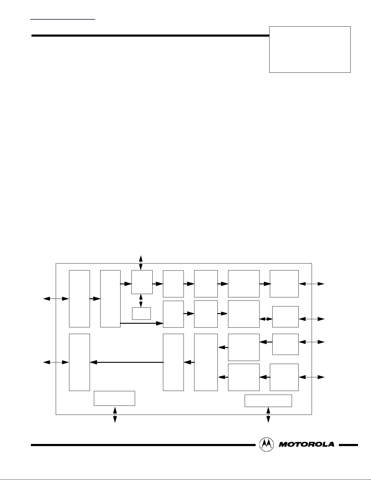
Figure 1. MC92052 Block Diagram
Reed-
Solomon
Decoder
Reed-
Solomon
Decoder
Reed-
Solomon
Encoder
Deran-
domizer
Deran-
domizer
Random-
izer
Rx Cell
Functions
Header
Interpretation
Header
Generation
Tx Cell
Functions
JTAG Controller
Rx
UTOPIA
I/F
Data
Link
Extraction
Data
Link
Insertion
Tx
UTOPIA
I/F

General Description
The MC92052 implements the TC sublayer of the DAVIC asymmetrical FTTC PHY specification for user devices. The MC92052 key functional blocks are described in
the paragraphs which follow.
Rx PMD Interface
The receive PMD interface receives a clock signal and
a serial data stream. The clock is used both to sample
the data and to clock the operation of the MC92052.
Frame Alignment
When in the “out-of-frame” condition, the frame alignment block searches the serial data (which is LSB first)
for the 16-bit framing pattern and then converts it to 8bit parallel data aligned to the framing pattern. When in
the “in-frame” condition, the serial-to-parallel block verifies the framing pattern and continues to convert it to
parallel data using the current alignment. In each frame,
the two framing bytes are discarded, the next 16 bytes
are provided to the header flow, and the following
(12 * 66) bytes are provided to the payload flow.
Deinterleaver
The deinterleaver block recovers the original data
blocks from the interleaved data that it receives. Transmitting interleaved data allows for better correction of
bursts of errors because the deinterleaver spreads the
incorrect data over many blocks so that the Reed-Solomon decoder can correct the small number of errors
in each block.
The deinterleaver separates the data byte stream into
33 branches. Each of the branches is delayed by a different amount, and then they are recombined into a single data stream. The delay of branch k (0 ≤ k ≤ 32) is
M * (32 - k). M is the Interleaving Depth Parameter recovered from the frame header and ranges from 0 to 31.
M=0 effectively disables the deinterleaver.
The delay of the interleaver/deinterleaver combination
is 1056 * M payload byte periods. The deinterleaver is
implemented using an external SRAM (Motorola
MCM6306 or equivalent). Alternatively, the internal
RAM can be used if the value of M is 1 or 2.
Reed-Solomon Decoders
One Reed-Solomon decoder is used for the header. It
decodes the (16,12) code in order to correct up to 2
bytes or declare the header to be uncorrectable.
The other decoder is used for the payload blocks. It decodes the (66,58) codes in order to correct up to 4 bytes
or declare the block to be uncorrectable, in which case
the data is not touched.
Derandomizers
The received data has been randomized on the network
side for better transmission performance. The derandomizers perform the inverse function to restore the
original data.
The two derandomizers are identical. One is used for
the 12 header bytes per frame, and the other is used for
the 12*58 payload bytes per frame. The derandomizers
are self-synchronizing since they depend only on the
previously received data.
Frame Header Interpretation Block
The header interpretation block extracts the useful information from the received frame header. It provides
information to the transmit flow regarding when to
transmit a cell, etc.
Data Link Extraction
The data link extraction block optionally provides the
data link bytes of the downstream frame headers to a
serial data link controller (e.g., MC68360 QUICC) for
further processing. The received downstream data link
bytes are extracted using a clock pin and a data pin.
Rx Cell Functions
The receive cell functions block recovers 53-octet ATM
cells from the derandomized byte stream using the
HEC-based method described in ITU-T Recommendation I.432.
Once the cell alignment has been recovered, the receive cell functions block checks the received HEC value against the calculated value and corrects single-bit
errors in the header. Any cell with non-correctable errors is discarded. Then the cells are filtered based on
the header value. Idle cells are discarded. Additional
cells may be discarded as a result of the GFC/VPI pattern matching option.
The cell functions block also derandomizes the payload
of the ATM cells to recover the original data and transfers entire ATM cells to the receive cell FIFO.
Counts of the cells transferred to the receive cell FIFO
and the cells that are discarded due to header errors are
maintained.
Rx UTOPIA Interface
The receive UTOPIA interface reads the ATM cells from
the receive cell FIFO and transfers them to the ATM layer according to the ATM Forum UTOPIA Level 1 speci-
Motorola MC92052
2
 Loading...