


MC909X Mobile Computer
Integrator Guide


MC909X Integrator Guide
72E-72216-06
Rev A
December 2007

ii MC909X Mobile Computer Integrator Guide
© 2005-7 by Motorola, Inc. All rights reserved.
No part of this publication may be reproduced or used in any form, or by any electrical or mechanical means,
without permission in writing from Motorola. This includes electronic or mechanical means, such as
photocopying, recording, or information storage and retrieval systems. The material in this manual is subject to
change without notice.
The software is provided strictly on an “as i s” basis. All sof twar e, including firmware, furnished to the user is on
a licensed basis. Motorola grants to the user a non-transferab le and non-exclusive license to use each
software or firmware program delivered hereunder (licensed program). Except as noted below, such license
may not be assigned, sublicensed, or otherwise transferred by the user without prior written consent of
Motorola. No right to copy a licensed program in whole or in part is granted, except as permitted unde r
copyright law. The user shall not modify, merge, or incorporate any form or portion of a licensed program with
other program material, create a derivative work from a licensed program, or use a licensed program in a
network without written permission from Motorola. The user agrees to maintain Motorola’s copyright notice on
the licensed programs delivered hereunder, and to include the same on any authorized copies it makes, in
whole or in part. The user agrees not to deco mpile, disassemble, decode, or reverse engineer any licensed
program delivered to the user or any portion thereof.
Motorola reserves the right to make changes to any software or product to improve reliability, function, or
design.
Motorola does not assume any product liability arising out of, or in connection with, the application or use of
any product, circuit, or application described herein.
No license is granted, either expressly or by implication, estoppel, or otherwise under any Motorola, Inc.,
intellectual property rights. An implied license only exists for equipment, circuits, and subsystems contained in
Motorola products.
MOTOROLA and the Stylized M Logo and Symbol and the Symbol logo are registered in the US Patent &
Trademark Office. Bluetooth is a registered trademark of Bluetooth SIG. Microsoft, Windows and ActiveSync
are either registered trademarks or trademarks of Microsoft Corporation. All other product or service names
are the property of their respective owners.
Motorola, Inc.
One Symbol Plaza
Holtsville, New York 11742-1300
http://www.motorola.com
Patents
This product is covered by one or more of the patents listed on the website: www.symbol.com/patents

Revision History
Changes to the original manual are listed below:
Change Date Description
Rev A 11/1/05 Initial release.
-02 Rev A 1/19/06 Add MC9090-K/S, MC9090-G and MC9094-K/S with Windows Mobile 5.0.
-03 Rev A 3/21/06 Add MC9097 support.
-04 Rev A 3/6/07 Add generic MC9097 information, 33-key keypad, Fusion 2.5 and AKU 3.2 update
-05 Rev A 9/15/07 Guide re-branding, incorporate Mobile OEM version 01.39.0001 and CE OEM version
iii
information.
01.26.0001 and add support for Haz Loc configurations.

iv MC909X Mobile Computer Integrator Guide

Table of Contents
Patents.................................................................................................................................................. ii
Revision History.................................................................................................................................... iii
About This Guide
Introduction........................................................................................................................................... xv
Documentation Set ......................................................................................................................... xv
Configurations....................................................................................................................................... xvi
Software Versions........................................................................................................................... xvii
Chapter Descriptions............................................................................................................................ xix
Notational Conventions......................................................................................................................... xx
Related Documents and Software........................................................................................................ xx
Service Information............................................................................................................................... xxi
Chapter 1: Getting Started
Introduction .......................................................................................................................................... 1-1
Unpacking the Mobile Computer ......................................................................................................... 1-1
Accessories ......................................................................................................................................... 1-5
Getting Started ..................................................................................................................................... 1-6
Installing and Removing the Main Battery ........................................................................................... 1-6
Installing the Main Battery .............................................................................................................. 1-6
Charging the Battery ............................................................................................................................ 1-7
Charging the Main Battery and Memory Backup Battery ............................................................... 1-7
Charging the Main Battery ............................................................................................................. 1-8
Charging Spare Batteries .................................................................................................................... 1-9
Removing the Main Battery ............................................................................................................ 1-9
Starting the Mobile Computer .............................................................................................................. 1-10
Calibrating the Screen ......................................................................................................................... 1-11
Checking Battery Status ...................................................................................................................... 1-11
Configuring the Mobile Computer ........................................................................................................ 1-11
Resetting the Mobile Computer ........................................................................................................... 1-12
Windows CE 5.0 Devices ............................................................................................................... 1-12
Performing a Warm Boot ......................................................................................................... 1-12
Performing a Cold Boot ............................................................................................................ 1-12

vi MC909X Integrator Guide
Windows Mobile 5.0 Devices ......................................................................................................... 1-12
Performing a Warm Boot ......................................................................................................... 1-13
Performing a Cold Boot ............................................................................................................ 1-13
Performing a Clean Boot .......................................................................................................... 1-13
SIM Card .............................................................................................................................................. 1-14
Stylus ................................................................................................................................................... 1-17
MC9090-G Strap .................................................................................................................................. 1-17
MC909X-S Strap .................................................................................................................................. 1-19
Battery Management ........................................................................................................................... 1-20
Battery Saving Tips ........................................................................................................................ 1-20
Changing the Power Settings .............................................................................................................. 1-20
Changing the Display Backlight Settings ............................................................................................. 1-21
Changing the Keypad Backlight Settings ............................................................................................. 1-21
Turning Off the Radios ......................................................................................................................... 1-21
On Devices with Mobile 5.0 AKU 1.0 ............................................................................................. 1-21
Turning Off the WLAN Radio ................................................................................................... 1-21
Bluetooth and WWAN Radios .................................................................................................. 1-22
On Devices with Mobile 5.0 AKU 2.2 or higher .............................................................................. 1-22
On Device with CE 5.0 (OEM Version 01.15 or lower) .................................................................. 1-23
WLAN Radio ............................................................................................................................ 1-23
Bluetooth Radio ....................................................................................................................... 1-24
On Device with CE 5.0 (OEM Version 01.16 or higher) ................................................................. 1-24
WLAN Radio ............................................................................................................................ 1-24
Bluetooth Radio ....................................................................................................................... 1-24
Chapter 2: Accessories
Introduction .......................................................................................................................................... 2-1
Keypads ......................................................................................................................................... 2-1
Cradles ........................................................................................................................................... 2-1
Miscellaneous ................................................................................................................................ 2-2
Snap-on Modules ........................................................................................................................... 2-2
Keypads ............................................................................................................................................... 2-2
Replacing the Keypad .................................................................................................................... 2-2
Multi Media Card (MMC) / Secure Device (SD) Card .......................................................................... 2-4
Single Slot Serial/USB Cradle ............................................................................................................. 2-5
Setup .............................................................................................................................................. 2-6
Battery Charging Indicators ........................................................................................................... 2-7
Four Slot Ethernet Cradle .................................................................................................................... 2-9
Setup .............................................................................................................................................. 2-10
Battery Charging Indicators ........................................................................................................... 2-11
Ethernet Communication Setup ..................................................................................................... 2-11
Installing MobileDox Cradle Manager ...................................................................................... 2-11
Installing iDockIt ....................................................................................................................... 2-11
Mobile Computer Configuration ............................................................................................... 2-12
DHCP Server Configuration ..................................................................................................... 2-12
Cradle Configuration ................................................................................................................ 2-12
Four Slot Charge Only Cradle ............................................................................................................. 2-16
Setup .............................................................................................................................................. 2-17
Battery Charging Indicators ........................................................................................................... 2-17

Table of Contents vii
Four Slot Spare Battery Charger ......................................................................................................... 2-18
Setup .............................................................................................................................................. 2-19
Spare Battery Charging with the Four Slot Spare Battery Charger ............................................... 2-19
Battery Charging Indicators ........................................................................................................... 2-19
Magnetic Stripe Reader ....................................................................................................................... 2-20
Attaching and Removing ................................................................................................................ 2-21
Setup .............................................................................................................................................. 2-21
Battery Charging Indicators ........................................................................................................... 2-22
Serial/USB Connection .................................................................................................................. 2-22
Using the MSR ............................................................................................................................... 2-22
Cable Adapter Module ......................................................................................................................... 2-23
Attaching and Removing ................................................................................................................ 2-24
Setup .............................................................................................................................................. 2-24
Battery Charging Indicators ........................................................................................................... 2-25
Serial/USB Connection .................................................................................................................. 2-25
Universal Battery Charger (UBC) Adapter ........................................................................................... 2-26
Inserting and Removing a Battery .................................................................................................. 2-26
Setup .............................................................................................................................................. 2-26
Battery Charging Indicators ........................................................................................................... 2-27
Modem Module .................................................................................................................................... 2-28
Setup .............................................................................................................................................. 2-29
Connecting to the Mobile Computer ........................................................................................ 2-29
Connecting to the Single Slot Serial/USB Cradle .................................................................... 2-30
Configuring the Mobile Computer for the Modem (Windows Mobile 5.0) ...................................... 2-30
Configuring the Mobile Computer for the Modem (Windows CE 5.0) ............................................ 2-32
Connecting the Modem (Windows Mobile 5.0) .............................................................................. 2-34
Connecting the Modem (Windows CE 5.0) .................................................................................... 2-34
Modem Country Setup ................................................................................................................... 2-35
Supported Countries ................................................................................................................ 2-35
AT Commands ............................................................................................................................... 2-35
Changing the Initialization String (Windows Mobile 2005) ....................................................... 2-36
Changing the Initialization String (Windows CE 5.0) ............................................................... 2-37
Basic AT Command Syntax ..................................................................................................... 2-39
Commands ............................................................................................................................... 2-40
Serial Communication Setup ............................................................................................................... 2-44
Setting Up a Connection on the Mobile Computer (Windows Mobile 2005) .................................. 2-44
Serial Connection Setup (Windows CE 5.0) .................................................................................. 2-46
USB Host Communication Setup ......................................................................................................... 2-48
Wall Mounting Bracket and Shelf Slide ................................................................................................ 2-49
Installing the Wall Mount Bracket ................................................................................................... 2-49
Attaching the Shelf Slide to the Wall Mount Bracket ...................................................................... 2-50
One Single Slot Cradle/Four Slot Battery Charger .................................................................. 2-50
Two Single Slot Cradles/Four Slot Battery Chargers ..................................................................... 2-50
Four Slot Cradle ....................................................................................................................... 2-51
Installing the Cradle/Charger on the Bracket ................................................................................. 2-51
Chapter 3: ActiveSync
Introduction .......................................................................................................................................... 3-1
Installing ActiveSync ............................................................................................................................ 3-1

viii MC909X Integrator Guide
Mobile Computer Setup ....................................................................................................................... 3-2
Setting Up an ActiveSync Connection on the Host Computer ............................................................. 3-3
Setting up a Partnership with a Windows CE 5.0 Device .............................................................. 3-4
Synchronization with a Windows Mobile 5.0 Device ...................................................................... 3-6
Chapter 4: Wireless Applications
Introduction .......................................................................................................................................... 4-1
Signal Strength Icon ............................................................................................................................ 4-2
Turning the WLAN Radio On and Off .................................................................................................. 4-3
Windows Mobile 5.0 ....................................................................................................................... 4-3
Windows CE 5.0 with Fusion 2.3 and Lower ................................................................................. 4-3
Windows CE 5.0 with Fusion 2.4 and Higher ................................................................................. 4-4
Find WLANs Application ...................................................................................................................... 4-5
Profile Editor Wizard ............................................................................................................................ 4-6
Profile ID ........................................................................................................................................ 4-6
Operating Mode ............................................................................................................................. 4-7
Ad-Hoc ........................................................................................................................................... 4-8
Authentication ................................................................................................................................ 4-9
Tunneled Authentication ................................................................................................................ 4-10
User Certificate Selection .............................................................................................................. 4-12
User Certificate Installation ...................................................................................................... 4-12
Server Certificate Selection ........................................................................................................... 4-12
Credential Cache Options .............................................................................................................. 4-14
User Name ............................................................................................................................... 4-15
Password ....................................................................................................................................... 4-15
Advanced Identity .......................................................................................................................... 4-16
Encryption ...................................................................................................................................... 4-16
Key Entry Page ........................................................................................................................ 4-18
Passkey Dialog ........................................................................................................................ 4-18
IP Address Entry ............................................................................................................................ 4-18
Transmit Power .............................................................................................................................. 4-20
Battery Usage ................................................................................................................................ 4-21
Manage Profiles Application .......................................................................................................... 4-22
Changing Profiles ..................................................................................................................... 4-23
Editing a Profile ........................................................................................................................ 4-24
Creating a New Profile ............................................................................................................. 4-24
Deleting a Profile ...................................................................................................................... 4-24
Ordering Profiles ...................................................................................................................... 4-24
Export a Profile ........................................................................................................................ 4-24
Wireless Status Application ................................................................................................................. 4-25
Signal Strength Window ................................................................................................................. 4-26
Current Profile Window .................................................................................................................. 4-27
IPv4 Status Window ....................................................................................................................... 4-28
Wireless Log Window .................................................................................................................... 4-29
Saving a Log .................................................................................................................. .......... 4-29
Clearing the Log ....................................................................................................................... 4-30
Versions Window ........................................................................................................................... 4-30
Wireless Diagnostics Application ......................................................................................................... 4-30
ICMP Ping Window ........................................................................................................................ 4-31

Table of Contents ix
Trace Route Window ..................................................................................................................... 4-32
Known APs Window .............................................................................................................. ......... 4-32
Options ................................................................................................................................................ 4-33
Operating Mode Filtering ............................................................................................................... 4-34
Regulatory Options ........................................................................................................................ 4-34
Band Selection ............................................................................................................................... 4-35
System Options .............................................................................................................................. 4-35
Change Password .......................................................................................................................... 4-36
Export ............................................................................................................................................. 4-37
Persistence .......................................................................................................................................... 4-38
Registry Settings .................................................................................................................................. 4-39
Log On/Off Application ......................................................................................................................... 4-40
User Already Logged In ................................................................................................................. 4-40
No User Logged In ......................................................................................................................... 4-40
Chapter 5: MC9094 Configuration
Introduction .......................................................................................................................................... 5-1
Quick Startup Steps ............................................................................................................................. 5-1
MC9094 Service Verification ............................................................................................................... 5-2
Ensuring Network Coverage .......................................................................................................... 5-2
Configuring an GPRS Data Connection ......................................................................................... 5-3
Establishing a Data Connection ..................................................................................................... 5-5
Ending an GPRS Data Connection ................................................................................................ 5-6
Phone Settings .................................................................................................................................... 5-7
Phone ............................................................................................................................................. 5-7
Sounds ..................................................................................................................................... 5-8
Security .................................................................................................................................... 5-8
Services ......................................................................................................................................... 5-9
Call Barring (Call Blocking) ...................................................................................................... 5-10
Caller ID ................................................................................................................................... 5-10
Call Forwarding ........................................................................................................................ 5-11
Call Waiting .............................................................................................................................. 5-11
Voice Mail and Short Message Service (SMS) ........................................................................ 5-12
Fixed Dialing .............................................................................................................. .............. 5-12
Network .......................................................................................................................................... 5-13
Changing Networks Manually .................................................................................................. 5-13
Viewing Available Networks ..................................................................................................... 5-14
Setting Preferred Networks ...................................................................................................... 5-15
Band ............................................................................................................................................... 5-17
Chapter 6: MC9097 Configuration
Introduction .......................................................................................................................................... 6-1
MC9097 Sprint Service Verification ..................................................................................................... 6-1
Ensuring Network Coverage .......................................................................................................... 6-1
Configuring an iDEN Data Connection .......................................................................................... 6-2
Establishing an iDEN Data Connection ......................................................................................... 6-4
Ending an Data Connection ........................................................................................................... 6-5
Phone Settings .................................................................................................................................... 6-7

x MC909X Integrator Guide
Phone ............................................................................................................................................. 6-7
Sounds ..................................................................................................................................... 6-7
Security .................................................................................................................................... 6-8
Services ......................................................................................................................................... 6-9
Call Barring (Call Blocking) ...................................................................................................... 6-10
Caller ID ................................................................................................................................... 6-10
Call Forwarding ........................................................................................................................ 6-10
Call Waiting .............................................................................................................................. 6-11
Voice Mail and Text Messages ................................................................................................ 6-11
Network .......................................................................................................................................... 6-12
Phone Info ...................................................................................................................................... 6-12
GPS ............................................................................................................................................... 6-13
Sys Stat .......................................................................................................................................... 6-14
Reg Stat ......................................................................................................................................... 6-15
Error Log ........................................................................................................................................ 6-16
Chapter 7: Application Deployment for WinCE 5.0
Software Installation on Development PC ........................................................................................... 7-1
DCP for MC9090 ............................................................................................................................ 7-1
Platform SDK ................................................................................................................................. 7-2
Symbol Mobility Developer Kits ..................................................................................................... 7-2
Installing Other Development Software ......................................................................................... 7-2
Deployment .......................................................................................................................................... 7-2
ActiveSync ..................................................................................................................................... 7-3
SD Card ......................................................................................................................................... 7-4
IPL .................................................................................................................................................. 7-4
Creating Hex Images ........................................................................................................................... 7-4
Starting Terminal Configuration Manager ...................................................................................... 7-5
Defining Script Properties .............................................................................................................. 7-8
Creating the Script for the Hex Image ............................................................................................ 7-9
Opening a New or Existing Script ............................................................................................ 7-9
Updating TCM 1.X Scripts ....................................................................................................... 7-9
Copying Components to the Script .......................................................................................... 7-10
Saving the Script ...................................................................................................................... 7-10
Building the Image ......................................................................................................................... 7-10
Sending the Hex Image Using IPL ....................................................................................................... 7-11
TCM Error Messages ..................................................................................................................... 7-16
IPL Error Detection ........................................................................................................................ 7-17
Creating a Splash Screen .............................................................................................................. 7-19
Splash Screen Format ................................................................................................................... 7-20
Flash Storage ...................................................................................................................................... 7-20
FFS Partitions ................................................................................................................................ 7-20
Working with FFS Partitions ........................................................................................................... 7-20
RegMerge.dll ............................................................................................................................ 7-21
CopyFiles ................................................................................................................................. 7-21
Non-FFS Partitions ........................................................................................................................ 7-22
Downloading Partitions to the Mobile Computer ............................................................................ 7-22

Table of Contents xi
Chapter 8: Application Deployment for Mobile 5.0
Introduction .......................................................................................................................................... 8-1
Security ................................................................................................................................................ 8-1
Application Security ....................................................................................................................... 8-1
Digital Signatures ........................................................................................................................... 8-1
Locking Down a Mobile Computer ........................................................................................... 8-2
Installing Certificates ................................................................................................................ 8-3
Device Management Security ........................................................................................................ 8-3
Remote API Security ...................................................................................................................... 8-3
Packaging ............................................................................................................................................ 8-4
Deployment .......................................................................................................................................... 8-4
Installation Using ActiveSync ......................................................................................................... 8-4
Installation Using Storage Card ..................................................................................................... 8-4
Installation Using AirBEAM ............................................................................................................ 8-5
MSP 3.X ......................................................................................................................................... 8-5
Image Update ................................................................................................................................ 8-5
Creating a Splash Screen .............................................................................................................. 8-6
XML Provisioning ................................................................................................................................. 8-7
Creating an XML Provisioning File ................................................................................................. 8-7
XML Provisioning vs. RegMerge and CopyFiles ............................................................................ 8-7
RegMerge ................................................................................................................................ 8-7
CopyFiles ................................................................................................................................. 8-8
Storage ................................................................................................................................................ 8-9
Random Access Memory ............................................................................................................... 8-9
Volatile File Storage (Cache Disk) ........................................................................................... 8-9
Persistent Storage ......................................................................................................................... 8-9
Application Folder .......................................................................................................................... 8-9
Symbol Configuration Manager ........................................................................................................... 8-10
File Types ...................................................................................................................................... 8-10
User Interface ................................................................................................................................ 8-10
Menu Functions ....................................................................................................................... 8-11
Parameter State Indicators ........................................................................................ .......... .... 8-12
Window Status Bar .................................................................................................................. 8-12
File Deployment ............................................................................................................................. 8-12
Symbol Mobility Developer Kits ........................................................................................................... 8-13
Chapter 9: Staging and Provisioning
Introduction .......................................................................................................................................... 9-1
Staging ................................................................................................................................................. 9-1
RD Client Version 1.9.0 ................................................................................................................. 9-1
Scanning RD Bar Codes .......................................................................................................... 9-3
RD Client Version 3.28 .................................................................................................................. 9-4
Bar Code Scanning ........................................................................................................................ 9-5
On-Demand Staging ...................................................................................................................... 9-7
ActiveSync Connection Mode .................................................................................................. 9-7
Ethernet Connection Mode ...................................................................................................... 9-7
Already existing IP Connection Mode ...................................................................................... 9-7
Well-known WLAN Connection Mode ...................................................................................... 9-7
RD Client Main Menu ..................................................................................................................... 9-10

xii MC909X Integrator Guide
Client Info ................................................................................................................................. 9-10
Log Menu ................................................................................................................................. 9-11
View Log .................................................................................................................................. 9-11
View Job Log ........................................................................................................................... 9-12
Set Log Level ........................................................................................................................... 9-12
Set Job Log Level .................................................................................................................... 9-13
Package List ............................................................................................................................ 9-13
Provisioning ......................................................................................................................................... 9-15
MSP Agent ..................................................................................................................................... 9-15
MSP Agent Main Menu ............................................................................................................ 9-15
AirBEAM Smart Client .................................................................................................................... 9-22
AirBEAM Package Builder ....................................................................................................... 9-22
AirBEAM Smart Client .............................................................................................................. 9-22
Chapter 10: Maintenance & Troubleshooting
Introduction .......................................................................................................................................... 10-1
Maintaining the Mobile Computer ........................................................................................................ 10-1
Battery Safety Guidelines .................................................................................................................... 10-1
Troubleshooting ................................................................................................................................... 10-2
Mobile Computer ............................................................................................................................ 10-2
Bluetooth Connection ..................................................................................................................... 10-4
Four Slot Charge Only Cradle ........................................................................................................ 10-5
Four Slot Ethernet Cradle .............................................................................................................. 10-6
Four Slot Spare Battery Charger ................................................................................................... 10-7
Single Slot Serial/USB Cradle ........................................................................................................ 10-8
Vehicle Cradle ................................................................................................................................ 10-9
Cable Adapter Module ................................................................................................................... 10-10
Magnetic Stripe Reader ................................................................................................................. 10-10
Modem Module .............................................................................................................................. 10-12
Appendix A: Technical Specifications
Technical Specifications ...................................................................................................................... A-1
Mobile Computer ............................................................................................................................ A-1
Accessory CAM and MSR Pin-Outs .................................................................................................... A-9
Non-Incendive Devices ........................................................................................................................ A-10
Appendix B: Using iDockIt
Introduction .......................................................................................................................................... B-1
Configuring iDockIt for Windows Mobile 5.0 ........................................................................................ B-2
Quick Start ..................................................................................................................................... B-2
How To Start iDockIt ................................................................................................................ B-3
How To Enable iDockIt To Manage Connections .................................................................... B-3
Minimize iDockIt ............................................................................................................................. B-4
Exit iDockIt ..................................................................................................................................... B-4
General Setup Options .................................................................................................................. B-4
Enable iDockIt .......................................................................................................................... B-4
Display Status When Cradled .................................................................................................. B-5

Table of Contents xiii
Display Settings When Cradled ............................................................................................... B-5
Reconnect Delay ...................................................................................................................... B-5
USB Cradle Type ..................................................................................................................... B-5
Auto-dismiss Error Dialogs ...................................................................................................... B-5
Status Tab ...................................................................................................................................... B-6
Ethernet Cradle Settings ................................................................................................................ B-7
Establish Network Connection ................................................................................................. B-7
Launch Application ................................................................................................................... B-7
Serial Cradle Baud Rate .......................................................................................................... B-7
Direct (Serial/USB) Settings ........................................................................................................... B-8
Launch ActiveSync .................................................................................................................. B-8
Establish Network Connection ................................................................................................. B-8
Launch Application ................................................................................................................... B-8
Serial Cradle Baud Rate .......................................................................................................... B-9
Modem Cradle Settings ................................................................................................................. B-9
Launch ActiveSync .................................................................................................................. B-9
Establish Network Connection ................................................................................................. B-9
Launch Application ................................................................................................................... B-10
Choose Connection ................................................................................................................. B-10
Create A New Modem Connection .......................................................................................... B-10
Edit an Existing Modem Connection ........................................................................................ B-11
Delete an Existing Modem Connection .................................................................................... B-11
Configuring iDockIt for Windows CE 5.0 .............................................................................................. B-12
Quick Start ..................................................................................................................................... B-12
How To Prepare the Mobile Computer To Connect ....................................................................... B-13
How To Start iDockIt ...................................................................................................................... B-13
How to Enable iDockIt to Manage Connections ............................................................................. B-13
Minimize iDockIt ............................................................................................................................. B-14
Exit iDockIt ..................................................................................................................................... B-14
General Recommendations ........................................................................................................... B-14
General Setup Options .................................................................................................................. B-15
Enable IDockIt .......................................................................................................................... B-15
Display Status When Cradled .................................................................................................. B-15
Display Settings When Cradled ............................................................................................... B-15
Reconnect Delay ...................................................................................................................... B-16
USB COM Port ......................................................................................................................... B-16
Auto-dismiss Error Dialogs ...................................................................................................... B-16
Status Tab ...................................................................................................................................... B-16
Ethernet Cradle Settings ................................................................................................................ B-17
Launch ActiveSync .................................................................................................................. B-18
Establish Network Connection ................................................................................................. B-18
Launch Application ................................................................................................................... B-18
Serial Port Baud Rate .............................................................................................................. B-18
Direct (Serial/USB) Settings ........................................................................................................... B-19
Launch ActiveSync .................................................................................................................. B-19
Establish Network Connection ................................................................................................. B-19
Launch Application ................................................................................................................... B-20
Serial Port Baud Rate .............................................................................................................. B-20
USB Notes ............................................................................................................................... B-20
Modem Cradle Settings ................................................................................................................. B-20

xiv MC909X Integrator Guide
Launch ActiveSync .................................................................................................................. B-21
Establish Network Connection ................................................................................................. B-21
Launch Application ................................................................................................................... B-21
Choose Connection ................................................................................................................. B-22
Create A New Modem Connection .......................................................................................... B-22
Edit An Existing Modem Connection ........................................................................................ B-22
Delete An Existing Modem Connection ................................................................................... B-23
Un-installing iDockIt ............................................................................................................................. B-23
Glossary
Index

About This Guide
Introduction
This guide provides information about settin g up and con fig u rin g MC 90 9X mobile computers and accessories.
NOTE Screens and windows pictured in this guide are samples and can differ from actual screens.
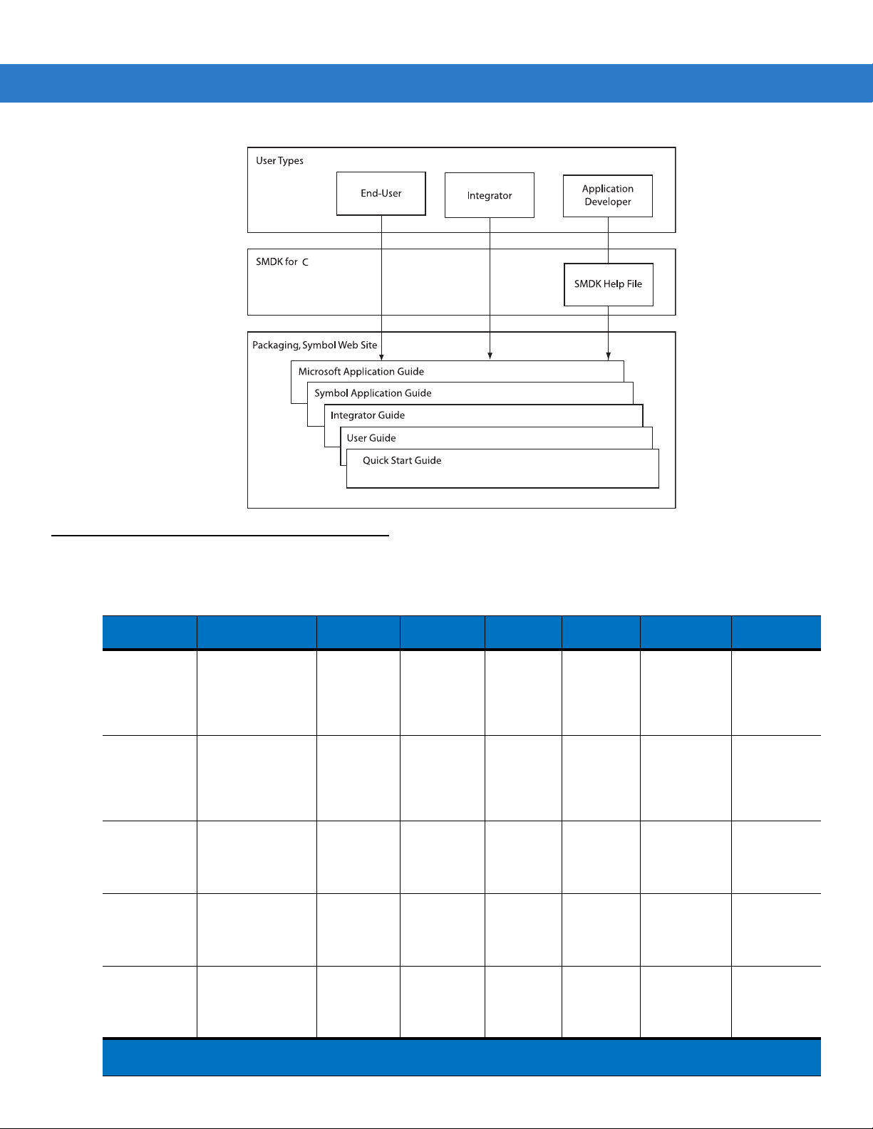
Documentation Set
The documentation set for the MC909X is divided into guides that provide information for specific user needs.
•
Microsoft Application Guide - describes how to use Microsoft developed applications.
•
Symbol Application Guide - describes how to use Symbol developed applications.
•
MC909X User Guide - describes how to use the MC909X mobile computer.
•
MC909X Integrator Guide - describes how to set up the MC909X mobile computer and the accessories.
•
SMDK Help File - provides API information for writing applications.
xvi MC909X Integrator Guide
Configurations
This guide covers the following configurations:
Configuration Radios Display Memory
MC9090-G WLAN: 802.11a/b/g
MC9090-G WLAN: 802.11a/b/g
MC9090-K WLAN: 802.11a/b/g
MC9090-S WLAN: 802.11a/b/g
MC9094-K WLAN 802.11a/b/g
1
Condensation Resistant configurations utilize desiccant located inside the mobile computer to capture internal
moisture that forms when they are carried from a warm humid environment to a cold environment.
WPAN: Bluetooth
WPAN: Bluetooth
WPAN: Bluetooth
WPAN: Bluetooth
WPAN: Bluetooth
WWAN:EDGE/
GPRS
Color or
monochrome
Color 64 MB RAM
Color 64 MB RAM
Color 64 MB RAM
Color 64 MB RAM
64 MB RAM
or 128 MB
RAM/
64 MB Flash
or 128 MB
RAM/
128 MB
Flash
or 128 MB
RAM/
128 MB
Flash
or 128 MB
RAM/
128 MB
Flash
or 128 MB
RAM/
128 MB
Flash
Data
Capture
Laser, Long
Range
Laser, or
Imager
Laser, Long
Range
Laser, or
Imager
Laser or
Imager
Laser or
Imager
Laser or
Imager
Operating
System
Windows
CE 5.0
Windows
Mobile 5.0
Premium
Edition
Windows
Mobile 5.0
Premium
Edition
Windows
Mobile 5.0
Premium
Edition
Windows
Mobile 5.0
Phone
Edition
Keypads Other
28-key,
43-key,
53-key,
VT, 3270,
5250
Emulators
28-key,
43-key,
53-key,
VT, 3270,
5250
Emulators
28-key,
33-key,
43-key,
53-key
28-key,
38-key alpha,
38-key
numeric
28-key,
33-key,
43-key,
53-key
Haz Loc
Class 1 Div 2
Condensation
Resistant
Haz Loc
Class 1 Div 2
Condensation
Resistant
Haz Loc
Class 1 Div 2
1
1
About This Guide xvii
Configuration Radios Display Memory
MC9094-S WLAN 802.11a/b/g
MC9097-K WLAN 802.11a/b/g
MC9097-S WLAN 802.11a/b/g
1
Condensation Resistant configurations utilize desiccant located inside the mobile computer to capture internal
WPAN: Bluetooth
WWAN:EDGE/
GPRS
WPAN: Bluetooth
WWAN: iDEN
WPAN: Bluetooth
WWAN: iDEN
Color 64 MB RAM
or 128 MB
RAM/
128 MB
Flash
Color 64 MB RAM
or 128 MB
RAM/
128 MB
Flash
Color 64 MB RAM
or 128 MB
RAM/
128 MB
Flash
Data
Capture
Laser or
Imager
Laser or
Imager
Laser or
Imager
Operating
System
Windows
Mobile 5.0
Phone
Edition
Windows
Mobile 5.0
Phone
Edition
Windows
Mobile 5.0
Phone
Edition
Keypads Other
28-key,
38-key alpha,
38-key
numeric
28-key,
33-key,
43-key,
53-key
28-key,
38-key alpha,
38-key
numeric
moisture that forms when they are carried from a warm humid environment to a cold environment.
Software Versions
This guide covers various software configurations and references are made to operating system or software
versions for:
•
Adaptation Kit Update (AKU) version
•
OEM version
•
Phone version
•
Fusion version.
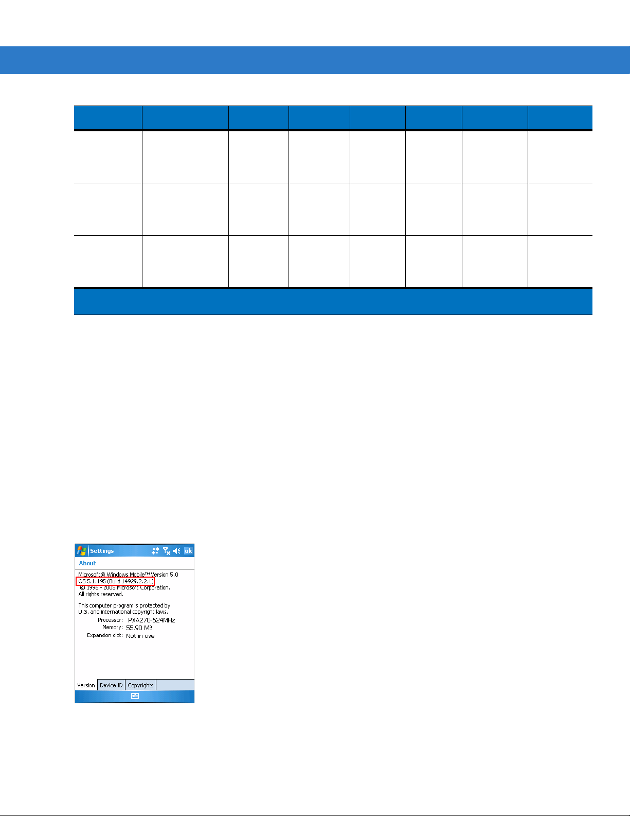
AKU Version for Mobile 5.0 Devices
To determine the Adaptation Kit Update (AKU) version on a Mobile 5.0 device:
Tap
Start > Settings > System tab > About icon > Version tab.
The second line lists the operating system version and the build number. The last part of the build number
represents the AKU number. For example, Build 14929.2.2.1 indicates that the device is running AKU version
2.2.1.
xviii MC909X Integrator Guide
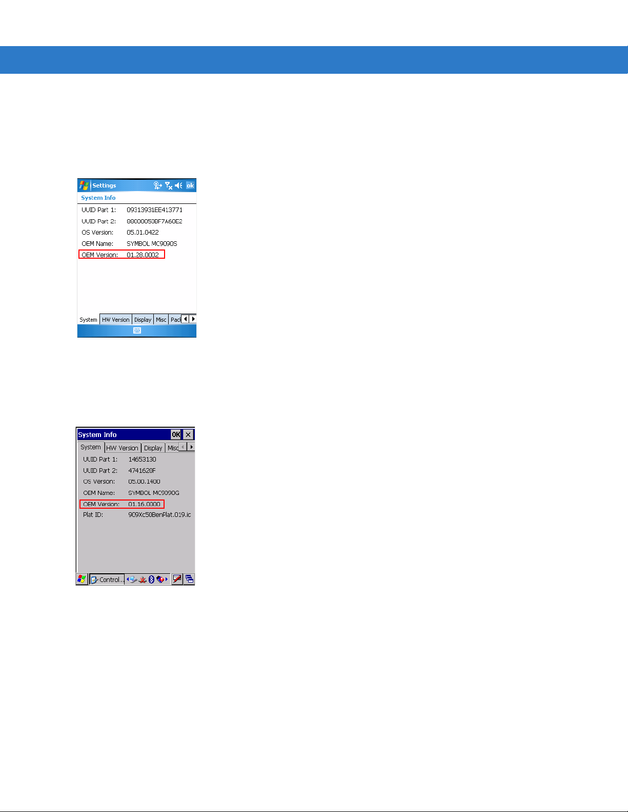
OEM Version on Mobile 5.0 Devices
To determine the OEM software version on a Mobile 5.0 device:
Tap
Start > Settings > System tab > System Information icon > System tab.
OEM Software on Windows CE 5.0 devices
To determine the OEM software version on a CE 5.0 device:
Tap
Start > Settings > Control Panel > System Information icon > System tab.
Fusion Software
To determine the Fusion software version on a Mobile 5.0 or Windows CE 5.0 device:
Tap
Wireless Strength icon > Wireless Status > Versions.

Phone Software
MC9094
MC9097
To determine the Phone software version on a Mobile 5.0 device:
Tap
Start > Phone > Menu > Options > Version Information tab.
About This Guide xix
Chapter Descriptions
Topics covered in this guide are as follows:
•
Chapter 1, Getting Started, provides information on charging the mobile computer battery and resetting.
•
Chapter 2, Accessories, describes the accessories available for the mobile computer and how to set up
power connections and battery charging capabilities, where applicable.
•
Chapter 3, ActiveSync, provides instructions on installing ActiveSync and setting up a partnership between
the mobile computer and a host computer.
•
Chapter 4, Wireless Applications, provides instructions using and configuring the mobile computer on a
wireless network.
•
Chapter 5, MC9094 Configuration, describes how to configure the WWAN MC9094 phone connection.
•
Chapter 6, MC9097 Configuration, describes how to configure the WWAN MC9097 phone connection.

xx MC909X Integrator Guide
•
Chapter 7, Application Deployment for WinCE 5.0, provides instructions for installing the Device
Configuration Package (DCP) for MC909X and the SMDK for C on the host computer and downloading
software and files to the mobile computer.
•
Chapter 8, Application Deployment for Mobile 5.0, describ es new fe at ur es in Windo ws Mo b ile 5. 0 inclu d ing
new security features, how to package applications, and procedures for deploying applications onto the
mobile computer.
•
Chapter 9, Staging and Provisioning, explains how to facilitate software downloads to the mobile computer.
•
Chapter 10, Maintenance & Troubleshooting, includes instructions on cleaning and storing the mobile
computer, and provides troubleshooting solutions for potential problems during mobile computer operation.
•
Appendix A, Technical Specifications, includes a table listing the technical specifications for the mobile
computer.
•
Appendix B, Using iDockIt, provides iDockIT software operating instructions.
Notational Conventions
The following conventions are used in this document:
•
“Mobile computer” refers to the Symbol MC909X series of hand-held computers.
•
Italics are used to highlight the following:
• Chapters and sections in this guide
• Related documents
•
Bold text is used to highlight the following:
• Dialog box, window and screen names
• Drop-down list and list box names
• Check box and radio button names
• Icons on a screen
• Key names on a keypad
• Button names on a screen.
•
Bullets (•) indicate:
• Action items
• Lists of alternatives
• Lists of required steps that are not nece ssarily sequential.
•
Sequential lists (e.g., those that describe step-by-s te p pr oc ed ur e s) ap pe a r as nu m be re d lists.
Related Documents and Software
The following documents provide more information about the MC909X mobile computers.
•
MC9090-G Quick Start Guide, p/n 72-72217-xx
•
MC909X-K/S Quick Start Guide, p/n 72-72220-xx
•
MC9097-K/S Quick Start Guide, p/n 72-72221-xx

About This Guide xxi
•
MC9090-G Windows® Mobile® 5.0 Regulatory Guide, p/n 72-72219-xx
•
MC9090-G Windows® CE 5.0 Regulatory Guide, p/n 72-7 2 21 8- xx
•
MC909X-K/S Windows® Mobile® 5.0 Regulatory Guide, p/n 72-73446-xx
•
MC909X User Guide, p/n 72E-72215-xx
•
Symbol Application Guide for Symbol Devices, p/n 72E-68901-xx
•
Microsoft Applications for Mobile and WinCE 5.0 User Guide, p/n 72E-78456-xx
•
Symbol Mobility Developer Kit (SMDK) Help File, p/n 72E-38880-03
•
Symbol Mobility Developer Kits, available at: http://support.symbol.com
•
Device Configuration Package (DCP for MC9090c50) and Platform SDK (PSDK9090c50) for MC9090-G with
Windows CE 5.0, available at: http://support.symbol.com.
•
ActiveSync software, available at: http://www.microsoft.com.
For the latest version of this guide and all guides, go to: http://support.symbol.com.
Service Information
If you have a problem with your equipment, contact the “Symbol Global Interactive Cente r,” for your region. Go to
http://www.symbol.com/contactsupport
contact that Business Partner for service.
Before contacting, have the model number and serial number at hand. If your problem cannot be solved by the
Symbol Global Interactive Center, you may need to return your equipment for servicing and you will be given
specific directions.
Motorola is not responsible for any damages incurred during shipment if the approved shipping container is not
used. Shipping the units improperly can possibly void the warranty.
. If you purchased your Symbol product from a Symbol Business Partner,

xxii MC909X Integrator Guide

Chapter 1 Getting Started
Introduction
This chapter lists the accessories for the mobile computer and explains how to install and charge the batteries,
replace the strap and start the mobile computer for the first time.
Unpacking the Mobile Computer
Carefully remove all protective material from around the mobile computer and save the shipping cont ainer for later
storage and shipping.
Verify that you received all equipment listed below:
•
mobile computer
•
lithium-ion battery
•
strap, attached to the mobile computer
•
stylus, in the stylus silo
•
Regulatory Guide
•
Quick Start Guide (poster).
Inspect the equipment for damage. If you are missing any equipment or if you find any damaged equipment,
contact the Symbol Technologies Support Center immediately. See Service Information on page xxi for contact
information.
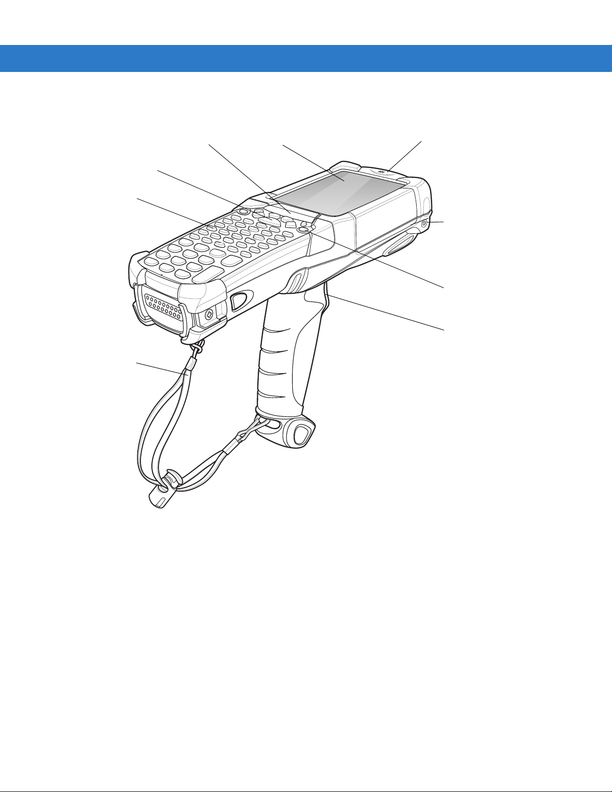
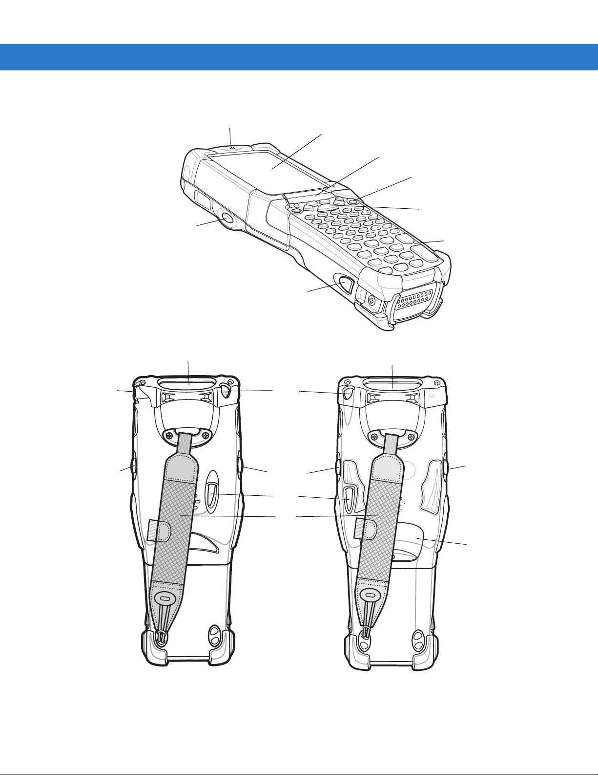
1 - 2 MC909X Integrator Guide
Handstrap
Keypad
Indicator LED Bar Touch Screen
Microphone (Windows
Mobile 5.0 only)
Headphone Jack
(Windows Mobile
5.0 only)
Scan Button
Power Button
Trigger
Figure 1-1
MC9090-G
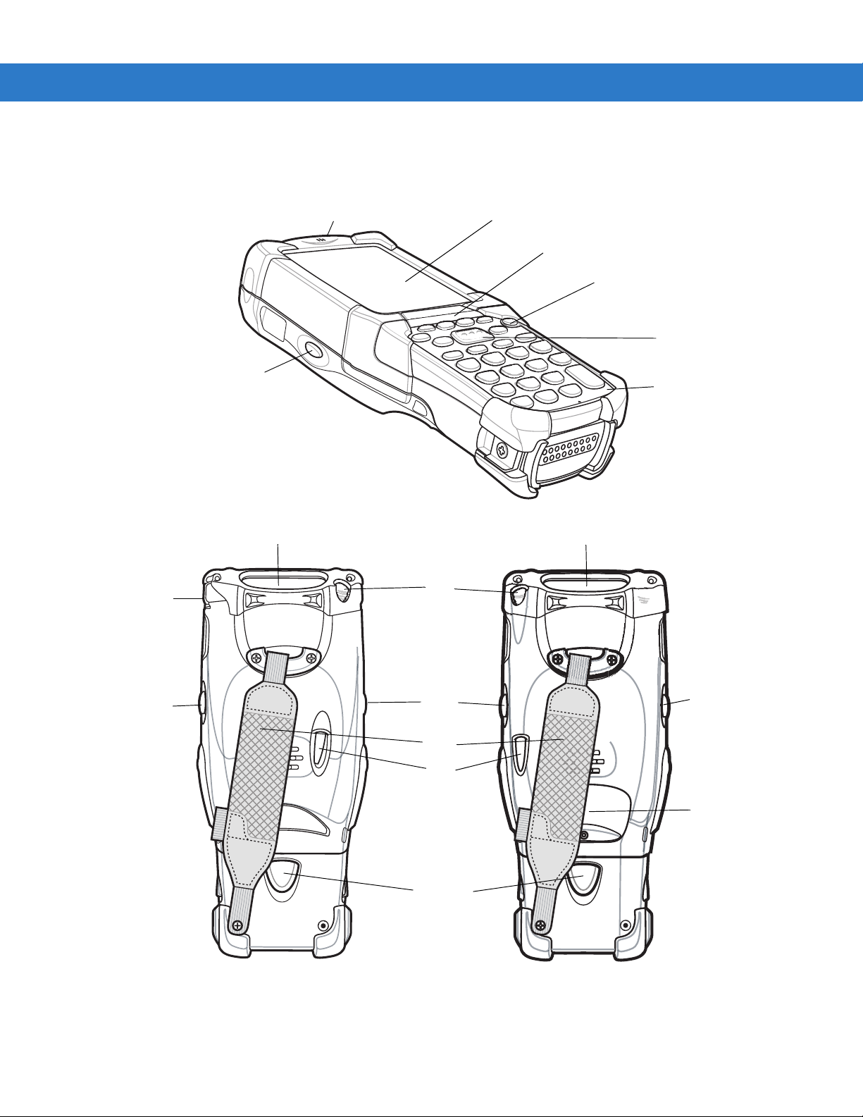
Scan Button
Keypad
Indicator LED Bar
Touch Screen
Microphone
Power
Scan Button
Exit Window
Headphone
Jack
Stylus
Strap
SIM Door
Scan Button or
Walkie-Talkie Button
on MC9097-K
Battery Release Latch
MC9090-K MC9094-K
MC9097-K
Exit Window
Scan Button or
Walkie-Talkie
Button
(MC9097-K)
Scan
Button
Stylus
Getting Started 1 - 3
Figure 1-2
MC909X-K
1 - 4 MC909X Integrator Guide
Scan
Button
Exit Window
Headphone
Jack
Stylus
Strap
Battery
Release
Latch
Scan Button
Keypad
Indicator LED Bar
Power Button
Touch Screen
Microphone
Scan Button or
Walkie-Talkie Button
on MC9097-S
Exit Window
MC9090-S
MC9094-S
MC9097-S
Scan
Button
Scan Button or
Walkie-Talkie
Button on
(MC9097-S)
SIM Door
Stylus
Figure 1-3
MC909X-S

Accessories
Table 1-1 lists the accessories available for the MC909X.
Getting Started 1 - 5
Table 1-1
Cable Adapter Module
(CAM)
Four Slot Charge Only
Cradle
Four Slot Ethernet Cradle Charges the mobile computer main battery and synchronizes the mobile computer
Vehicle Cradle Installs in a vehicle and charges the mobile computer main battery and a sp are battery.
Four Slot Spare Battery
Charger
MC909X Accessories
Accessory Description
Snap-on required to connect the following cables to the mobile computer.
•
AC line cord (country-specific) and power supply, charges the mobile
computer.
•
Auto charge cable, charges the mobile computer using a vehicle’s cigarette
lighter.
•
DEX cable, connects the mobile computer to a vending machine.
•
Serial cable, adds serial communication capabilities.
•
USB cable, adds USB communication capabilities.
•
Printer cable, adds printer communication capabilities.
Charges the mobile computer main battery.
with a host computer through an Ethernet connection.
Provides serial data communication between the mobile computer and an external
device.
Charges up to four mobile computer spare batteries.
Headphones Use in noisy environments.
Holster Holds the mobile computer when not in use.
Keypads (Optional) Application specific keypads.
Magnetic Stripe Reader
(MSR)
Modem Module Enables data communication between the mobile computer and a host computer,
Multimedia Card (MMC) Provides secondary non-volatile storage.
Single Slot Serial/USB
Cradle
Software Symbol Mobility Developer Kits available at: http://support.symbol.com.
Spare lithium-ion battery Replacement battery.
Snaps on to the mobile computer and adds magstripe read capabilities.
remotely through the phone lines, and synchronizes information between the mobile
computer and a host computer.
Charges the mobile computer main battery and a spare battery. It also synchronizes
the mobile computer with a host computer through either a serial or a USB connection.
Device Configuration Package (DCPforMC9090c50) and Platform SDK
(PSDK9090c50) for MC9090-G with Windows CE 5.0 only, available at:
http://support.symbol.com.
1 - 6 MC909X Integrator Guide
Table 1-1
Stylus Performs pen functions.
Universal Battery Charger
Adapter
Wall Mounting Bracket and
Shelf Slide
MC909X Accessories (Continued)
Accessory Description
Getting Started
In order to start using the mobile computer for the first time:
•
install the main battery
•
charge the main battery and backup battery
•
start the mobile computer
•
configure the mobile computer.
The main battery can be charged before or after it is installed. Use one of the sp a re ba ttery cha rgers to char ge the
main battery (out of the mobile computer), or one of the cradles to charge the main battery installed in the mobile
computer.
Adapts the UBC for use with the Series 9000 batteries.
Use for wall mounting applications.
Installing and Removing the Main Battery
Installing the Main Battery
Before using the mobile computer, install a lithium-ion battery by sliding the battery into the mobile computer as
shown in Figure 1-4.
NOTE Ensure the battery is fully inserted. Two audible clicks can be heard as the battery is fully inserted. A partially
inserted battery may result in unintentional data loss.
When a battery is fully inserted in a mobile computer for the first time, upon the mobile computer’s first power up,
the device boots and powers on automatically.
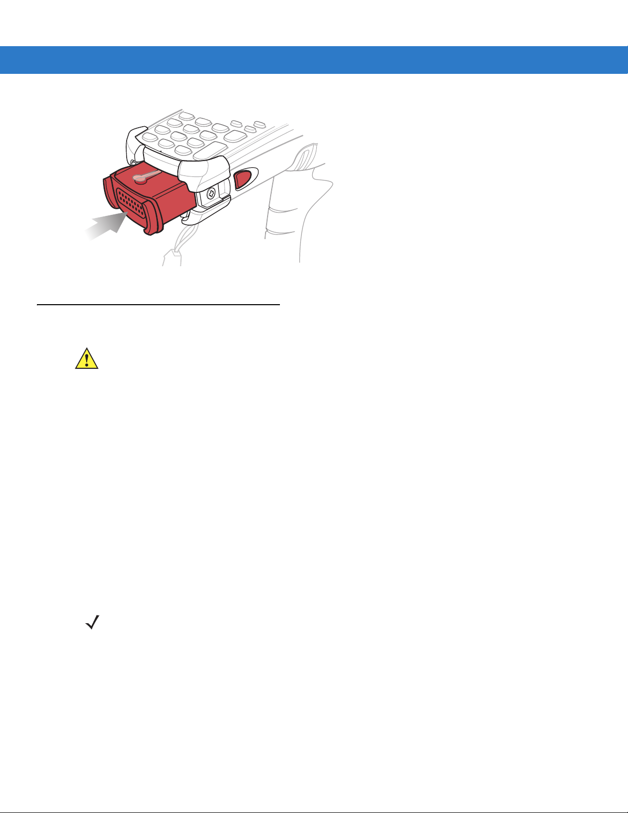
Getting Started 1 - 7
Figure 1-4
Installing the Main Battery
Charging the Battery
CAUTION Ensure that you follow the guidelines for battery safety described in Battery Safety Guidelines on page
10-1.
Charging the Main Battery and Memory Backup Battery
Before using the mobile computer for the first time, charge the main battery until the amber charge indicator light
remains lit (see Table 1-2 on page 1-8 for charge status indications). The main battery fully charges in less than
four hours. The mobile computer can be charged using a cradle, the CAM, or the MSR with the appropriate power
supply.
The mobile computer is also equipped with a memory backup battery which automatically charges from the main
battery whether or not the mobile computer is operating or is in suspend mode. The memory backup battery retains
data in memory for at least 30 minutes when the mobile computer's main battery is removed or fully discharged.
When the mobile computer is used for the first time or after the memory backup battery has fully discharged, the
memory backup battery requires approximately 15 hours to fully charge. Do not remove the main battery from the
mobile computer for 15 hours to ensure that the memory backup battery fully charges. If the main battery is
removed from the mobile computer or the main battery is fully discharged, the memory backup battery completely
discharges in several hours.
When the main battery reaches a very low battery state, the combination of main battery and backup battery
retains data in memory for at least 72 hours.
NOTE Do not remove the main battery within the first 15 hours of use. If the main battery is removed before the
backup battery is fully charged, data may be lost.
Use the following to charge batteries:
•
Cradles: The mobile computer slips into the cradles for charging the battery in the mobile computer (and
spare batteries, where applicable).
• Single Slot Serial/USB Cradle.
• Four Slot Ethernet Cradle and Four Slot Charge Only Cradles.

1 - 8 MC909X Integrator Guide
•
Accessories: The mobile computer’s snap-on accessories provide charging capability, when used with one of
the accessory charging cables.
• CAM
• MSR.
•
Chargers: The mobile computer’s spare battery charging accessories are used to charge batteries that are
removed from the mobile computer.
• Single Slot Serial/USB Cradle
• Four Slot Spare Battery Charger
• Universal Battery Charger (UBC).
NOTE To achieve the best battery life in mobile computers with multiple radios, turn off the radios that are not being
used. See Turning Off the Radios on page 1-21 for more inofrmation.
Charging the Main Battery
Charge the main battery in the mobile computer usin g a cra d le, the CAM with a ch ar gin g cable , or the M SR w ith
the appropriate power supply.
1. Ensure the accessory used to charge the main battery is connected to the appropriate power source (see
Chapter 2, Accessories for setup information).
2. Insert the mobile computer into a cradle or attach the appropriate snap-on module.
3. The mobile computer starts to charge au tomatically. The amber charge LED, in the Indicator LED Bar, lights to
show the charge status. See Table 1-2 for charging indications.
The main battery usually fully charges in less than four hours.
Table 1-2
Off Mobile computer not in cradle or the mobile computer is not attached to the CAM or MSR.
Fast Blinking Amber Error in charging; check placement of the mobile computer.
Slow Blinking Amber Mobile computer is charging.
Solid Amber Charging complete.
Mobile Computer LED Charge Indicators
LED Indication
Mobile computer not placed correctly. Charger is not powered.
Note: When the battery is initially inserted in the mobile computer, the amber LED flashes
once if the battery power is low or the battery is not fully inserted.

Charging Spare Batteries
CAUTION Ensure that you follow the guidelines for battery safety described in Battery Safety Guidelines on page
10-1.
Use the following three accessories to charge spare batteries:
•
Single Slot Serial/USB Cradle
•
Four Slot Spare Battery Charger
•
UBC Adapter.
To charge a spare battery:
1. Ensure the accessory used to charge the spare battery is connected to the appropriate power sou rc e (se e
Chapter 2, Accessories for setup information).
2. Insert the spare battery into the accessory’s spare battery charg ing slot with the charging cont acts facing down
(over the charging pins) and gently press down on the battery to ensure proper contact.
3. The battery starts to charge automatically. The amber charge LED on the accessory lights to show the charge
status. See Chapter 2, Accessories for charging indications for th e accessory.
Getting Started 1 - 9
The battery usually fully charges in less than four hours.
Removing the Main Battery
To remove the main battery:
1. Prior to removing the battery, press the red Power button to place the mobile computer in the suspend mode.
2. For the MC9097, wait 10 seconds before proceeding to the n ext step. If you do not, you may need to perform a
warm boot after replacing the battery.
3. Press the primary battery release(s). The battery partially ejects from the mobile computer.
4. Pause three to four seconds while the mobile computer performs battery removal shutdown.
5. Press the secondary battery release, on top of the battery, and slide the battery out of the mobile computer.

1 - 10 MC909X Integrator Guide
1
2
1
3
Primary Battery Releases
Secondary Battery Release
Primary Battery Release
Secondary Battery
Release
Figure 1-5
Figure 1-6
Removing the Main Battery
Removing the Main Battery - MC909X-S
Starting the Mobile Computer
Press the red Power button to turn on the mobile computer. If the mobile computer does not power on, perform a
cold boot. See Performing a Cold Boot on page 2-41.
NOTE When a battery is fully inserted in a mobile computer for the first time, upon the mobile computer’s first
power up, the device boots and powers on automatically.
When the mobile computer is powered on for the first time, it initializes its system. The splash screen (Figure 1-7)
appears for a short period of time.

Getting Started 1 - 11
MC9090/4 MC9097
OR
Figure 1-7
Symbol Splash Window
Calibrating the Screen
To calibrate the screen so that the cursor on the touch screen aligns with the tip of the stylus:
1. Using the stylus carefully press and briefly hold the tip of stylus on the center of each t arget that appea rs on the
screen.
NOTE To re-calibrate the screen at anytime, press Blue key + ESC on the mobile computer to launch the
calibration screen application.
2. Repeat as the target moves around the screen or press ESC to cancel.
Checking Battery Status
To check whether the main battery or backup battery in the mobile computer is charged, tap Start > Settings >
Control Panel > Power icon to display the Battery Status window.
To save battery power, set the mobile computer to turn off after a specified number of minutes.
Configuring the Mobile Computer
•
To customize the mobile computer settings, refer to the Microsoft Applications for Mobile and CE 5.0 User
Guide.
•
To set up ActiveSync to synchronize the mobile computer with the host computer, see Chapter 3, ActiveSync.
•
To configure the mobile computer for wireless LAN network, see Chapter 4, Wireless Applications.
•
To configure the mobile computer for WWAN network, see Chapter 5, MC9094 Configuration.
•
To configure the mobile computer for iDEN network, see Chapter 6, MC9097 Configuration.
•
To deploy software on the mobile computer, see Chapter 7, Application Deployment for WinCE 5.0 or
Chapter 8, Application Deployment for Mobile 5.0.

1 - 12 MC909X Integrator Guide
Resetting the Mobile Computer
Windows CE 5.0 Devices
There are two reset functions, warm boot and cold boot. A warm boot restarts the mobile computer by closing all
running programs.
A cold boot also restarts th e mobile computer, but erases all stored records and entries in RAM. Data saved in flash
memory or a memory card is not lost. In addition it returns formats, preferences and other settings to the factory
default settings.
Perform a warm boot first. This rest art s the mobile computer an d saves all stored records and entries. If the mobile
computer still does not respond, perform a cold boot.
Performing a Warm Boot
Hold down the Power button for approximately five seconds. As soon as the mobile computer starts to perform a
warm boot release the Power button.
Performing a Cold Boot
A cold boot restarts the mobile computer and er ases all user stor ed records and entries that are not saved in flash
memory (Application and Platform folders) or a memo ry card. Never pe rfor m a cold boo t unless a warm boo t d oes
not solve the problem.
CAUTION Do not hold down any key, other than the Power button during a reset. Performing a cold boot restores
formats, preferences and other settings to the default settings.
NOTE Any data previously synchronized with a computer can be restored during the next ActiveSync operation.
To perform a cold boot:
1. Press the primary battery release on the mobile computer to partially eject the battery from the mobile
computer.
2. While the battery is partially released, simultaneously press and release the handle trigger and the Power
button.
3. Push the battery to fully re-insert it in the mobile computer. One au dible click can be heard as the battery is fully
inserted.
4. The mobile computer initializes.
5. Calibrate the screen.
Windows Mobile 5.0 Devices
There are three reset functions, warm boot, cold boot and clean boot.
•
A warm boot restarts the mobile computer and closes all running programs.
•
A cold boot also restarts the mobile computer and closes all running programs but also resets the
Real-Time-Clock (RTC).

Getting Started 1 - 13
•
A clean boot resets the mobile computer to the factory default settings.
Data saved in flash memory or a memory card is not lost. Perform a warm boot first. This restarts the mobile
computer and saves all stored records and entries. If the mobile computer still does not respond, perform a cold
boot.
Performing a Warm Boot
Hold down the Power button for approximately five seconds. As soon as the mobile computer starts to perform a
warm boot release the Power button.
Performing a Cold Boot
A cold boot restarts the mobile computer. The operating system and all applications are restarted. File storage is
preserved. The Real-Time-Clock (RTC) resets. Only perform a cold boot if a warm boot does not solve the
problem.
To perform a cold boot:
1. Press the primary battery release on the mobile computer to partially eject the battery from the mobile
computer.
2. On an MC9090-G, while the battery is partially released, simultaneously press and release the trigger and the
Power button.
or
On an MC-909X-K or MC909X-S, while the battery is partially released, simulta neously press and release the
left scan button and the Power button .
3. Push the battery to fully re-insert it in the mobile computer. One au dible click can be heard as the battery is fully
inserted.
4. The mobile computer initializes.
Performing a Clean Boot
CAUTION A clean boot shoul d only be performed by an authorized system administrator. You must connect the
mobile computer to AC power during a clean boot.
Removing AC power from the mobile computer during a clean boot may render the mobile computer
inoperable.
A clean boot resets the mobile computer to the fa ctory default setting s. All dat a is th e Application folder is retained.
You must download the Clean Boot Package file from the Symbol Support Central and install on the mobile
computer.
To perform a clean boot:
1. Download the Clean Boot Package from the Symbol Support Central. Follow the instructions included in the
package for installing the package onto the mobile computer.
2. Press the primary battery release on the mobile computer to partially eject the battery from the mobile
computer.
3. On an MC9090-G, while the battery is partially released, simultaneously press and release the trigger and the
Power button.
or

1 - 14 MC909X Integrator Guide
On an MC909X-K or MC909X-S, while the battery is partially released, simultaneously press and release the
left scan button and the Power button .
NOTE After you insert the battery you have two seconds to press the trigger or left scan button.
4. Push the battery to fully re-insert it in the mobile computer. One au dible click can be heard as the battery is fully
inserted.
5. On the MC9090-G, press and hold the trigger.
or
On the MC909X-K or MC909X-S, press and hold the left scan button.
6. Connect the mobile computer to AC power using the CAM or inse rt the mobile co mputer into a powered cradle.
7. The mobile computer updates and then re-boots.
8. The calibration screen appears.
SIM Card
The SIM card, or smart card, is required for MC9094 (GPRS) and MC9097 (iDEN) phone service. The SIM card for
the MC9094 must be obtained from the phone service provider. The MC9097 comes from the factory with the
inactive SIM card pre-installed. The card fits into the mobile computer and can contain the following information:
•
•
•
•
To install the SIM card:
1. Place the mobile computer into the suspend mod e by pre ssing th e re d Power button.
2. Remove the SIM door on the back of the mobile computer.
NOTE Subscriber Identification Module (SIM) card is only used in the MC9094 and MC9097 configurations.
Mobile phone service provider account details.
Information regarding service access and preferences.
Contact information, which can be moved to Contacts on the mobile computer.
Any additional services to which the user may have subscribed.
NOTE For more information about SIM cards, refer to the mobile phone service provider's documentation.

Getting Started 1 - 15
SIM
Door
SIM Holder
Figure 1-8
3. Unlock the SIM holder by sliding the metal clip to the open position.
4. Lift the SIM holder.
Figure 1-9
5. Insert the SIM card, as shown in Figure 1-10, with the cut edge of the card facing the top of the mobile
Removing SIM Door
Unlock SIM Case
computer and the contacts facing down.
6. Lower the SIM holder.
Figure 1-10
7. Lock the metal clip by sliding it to the closed position.
Inserting the SIM Card

1 - 16 MC909X Integrator Guide
Figure 1-11
8. Replace the SIM door with one screw .
Figure 1-12
9. Press the red Power button.
10. On the MC9097, you must preform a master rest after installing a new SIM card.
a. Tap Start > Phone > Menu > Options > Error Log tab.
b. Tap the Master Reset button.
Locking the SIM Card Housing
Replacing the SIM Door
NOTE On the MC9097, it is not recommended that you swap the SIM card with another SIM card. If you do swap
SIM cards, perform step 10.
c. Tap OK.
d. Once an “X” appears in the Phone Antenna icon (wait a few seconds), perform a warm boot.
e. Wait for the mobile computer to reboot and then perform a second warm boot.
11. Tap Start > Phone > Menu > Options > Network tab and verify that the service provider appears in the Current
network:
12. Make a call to verify connection.
field.
NOTE For detailed information about WWAN activation and settings, refer to Chapter 5, MC9094 Configuration or
Chapter 6, MC9097 Configuration.
On the MC9097, if the SIM door is removed without removing the SIM card, you must warm boot the mobile
computer.
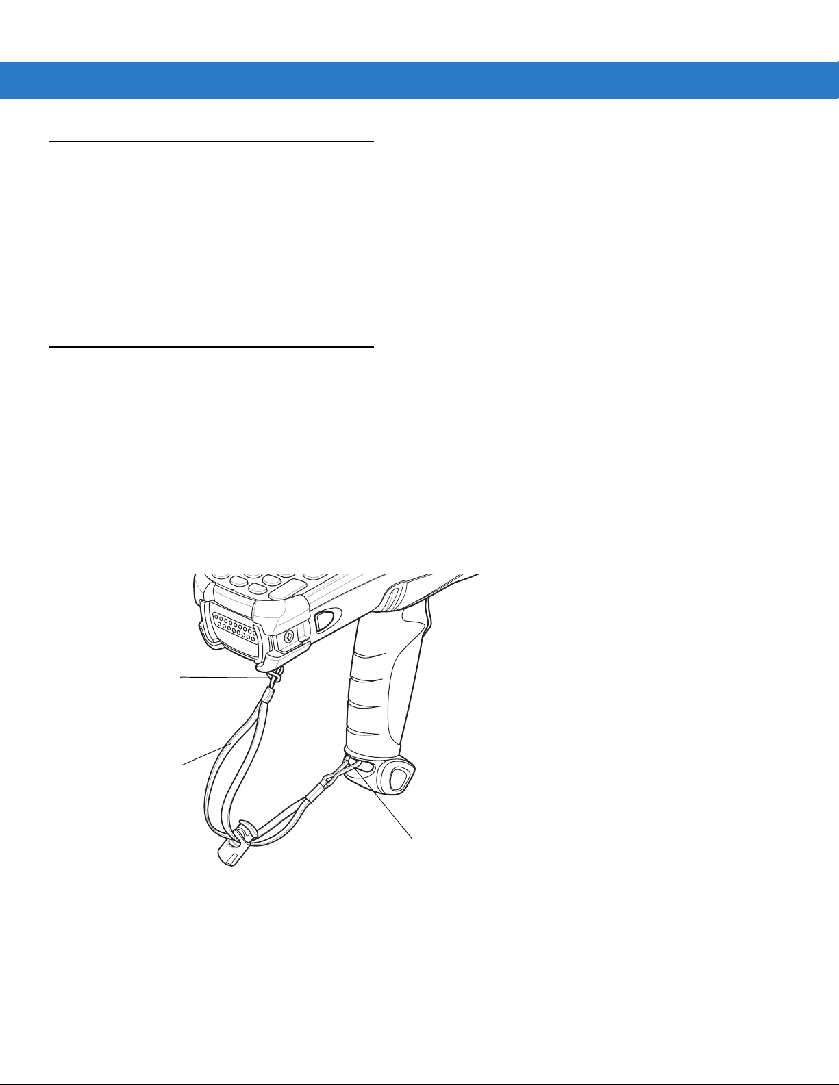
Stylus
Metal Clip
Strap Loop
Handstrap
Use the mobile computer stylus for selecting items and entering information. The stylus functions as a mouse.
•
Tap: Touch the screen once with the stylus to press option buttons and open menu items.
•
Tap and Hold: Tap and hold th e stylus on an item to see a list of actions available for that item. On the pop-up
menu that appears, tap the action you want to perform.
•
Drag: Hold the stylus on the screen and drag across the screen to select text and images. Drag in a list to
select multiple items.
MC9090-G Strap
The strap may be moved to either the left or right side of the mobile computer to suit user preferences.
To reposition the strap:
1. Disconnect the metal clip at the handle.
Getting Started 1 - 17
2. Open strap loop and slide the handstrap through the loop.
3. Slide the loop out of the connector post.
4. Reverse the procedure to re-attach the strap. Two strap connectors are provided on the mobile computer’s
main body. The handstrap may be attached to either connector.
Figure 1-13
Reposition the Strap

1 - 18 MC909X Integrator Guide
Loop
Button
Connection Post
MC909X-K Strap
The strap may be moved to either the left or right side of the mobile computer to suit user preferences. To
reposition the MC909X-K strap:
1. Lift the loop end of the strap over the button.
Figure 1-14
2. Pull the loop through the connection post.
3. Remove the battery.
4. Insert the loop into the opposite connection post.
5. Place the loop over the button and pull taught.
6. Replace the battery.
Repositioning the MC909X-K Strap
To replace the handstrap:
1. Remove two screws securing the strap bracket to the device.
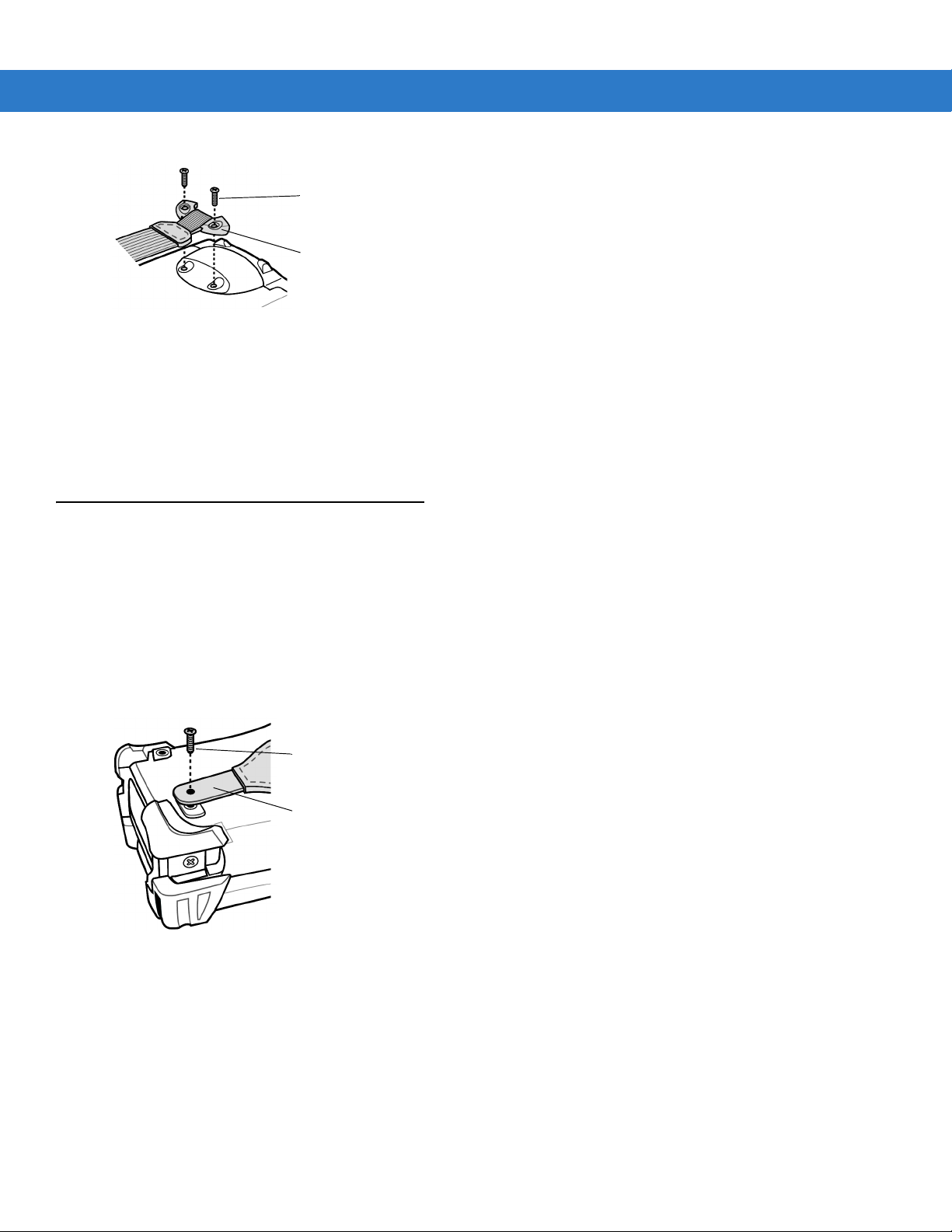
Getting Started 1 - 19
Screws
Strap Bracket
Screw
Strap Bracket
Figure 1-15
2. Lift the loop end of the strap over the button.
3. Pull the loop through the connection post.
4. Remove the battery.
5. Reverse the procedure to re-attach the strap.
Remove Strap Bracket
MC909X-S Strap
The strap may be moved to either the left or right side of the mobile computer to suit user preferences. To
reposition the MC909X-S strap, attach the MC909X-S strap to either the lef t or right side of the mobile computer to
suit user preferences. To reposition the strap:
1. Remove the screw securing the bottom of the strap to the device.
2. Position the bottom end of the strap over the opposite screw hole.
3. Secure the strap to the device.
Figure 1-16
Repositioning the MC909X-S Strap
To replace the handstrap:
1. Remove two screws securing the strap bracket to the device.

1 - 20 MC909X Integrator Guide
Screws
Strap Bracket
Figure 1-17
2. Remove the screw securing the bottom of the strap to the device.
3. Reverse the procedure to re-attach the strap.
Remove Strap Bracket
Battery Management
Battery Saving Tips
•
Leave the mobile computer connected to AC power at all times when not in use.
•
Set the mobile computer to turn off after a short period of non-use.
•
Set the display and keyboard backlight to turn off after a short period of non-use.
•
Turn off all wireless radio activity when not in use.
•
Power off the mobile computer when charging to charge at a faster rate.
Changing the Power Settings
To set the mobile computer to turn off after a short period of non-use:
1. On devices with Windows CE 5.0, tap Start > Settings > Control Panel > Power icon > Power Off tab.
or
On devices with Windows Mobile 5.0, tap
2. Select the On battery power: Turn off device if not used for: check box and select a value from the drop-down list
box.
3. Tap OK.
Start > Settings > System tab > Power icon > Advanced tab.

Changing the Display Backlight Settings
To change the display backlight settings in order to conserve more battery power:
1. On devices with Windows CE 5.0, tap Start > Settings > Control Panel > Backlight icon > Battery Power tab.
or
Getting Started 1 - 21
On devices with Windows Mobile 5.0, tap
2. Select the On battery power: Disable backlight if not used for: check box and select a value from the drop-down
list box.
3. Tap th e Brightness tab.
4. Tap th e Dis able backlight check box to completely turn off the display backlight.
5. Use the slider to set the brightness of the backlight. Set it to a low value to save battery power.
6. Tap OK.
Start > Settings > System tab > Backlight icon > Battery Power tab.
Changing the Keypad Backlight Settings
To chang e th e key pad backlig ht sett ing s in or de r to cons er ve mor e battery power:
1. On devices with Windows CE 5.0, tap Start > Settings > Control Panel > Keylight icon > Battery Power tab.
or
On devices with Windows Mobile 5.0, tap
2. Select the On battery power: Disable keylight if not used for: check box and select a value from the drop-down
list box.
3. Tap th e Advanced tab.
Start > Settings > System tab > Keylight icon > Battery Power tab.
4. Tap th e Dis able keylight check box to completely turn off the display backlight.
5. Tap OK.
Turning Off the Radios
On Devices with Mobile 5.0 AKU 1.0
NOTE To determine the operating system AKU version, see Software Versions on page xvii.
Turning Off the WLAN Radio
To turn off the WLAN radio tap the Wireless Connection Status icon at the bottom of the Today screen and select
Disable Radio. A red X appears across the icon indicating that the radio is disabled (off).

1 - 22 MC909X Integrator Guide
Wireless Connection Status Icon
Figure 1-18
To turn the radio back on, tap the
Enable Radio. The red X disappears from the icon indicating that the radio is enabled (on).
Wireless Connection Status Icon
Wireless Connection Status icon at the bottom of the Today screen and select
Bluetooth and WWAN Radios
NOTE The Flight Mode feature only turns off the WWAN and Bluetooth radios. The WLAN radio must be turned
off separately.
To turn off the Bluetooth and WWAN radios, tap the Connectivity icon (on non-WWAN devices) or the
Antenna/Signal icon (on WWAN devices) and select Turn On Flight Mod e.
NOTE On the MC9097, it takes two to five seconds for the radio to shut down.
To turn on the Bluetooth and WWAN radios, tap the
Antenna/Signal icon (on WWAN devices) and select Turn Off Flight Mode.
NOTE On the MC9097, wait 20 to 40 seconds for the radio to power on. During this time do not suspend the
mobile computer or remove the battery. If the mobile computer is suspended or the battery is removed,
warm boot the mobile computer.
Connectivity icon (on non-WWAN devices) or the
On Devices with Mobile 5.0 AKU 2.2 or higher
NOTE To determine the operating system AKU version, see Software Versions on page xvii.
Windows Mobile 5.0 devices with AKU 2.2 or higher include Wireless Manager, which provides a simple method of
enabling, disabling, and configuring all the device’s wireless capabilities in one place.
To open
Figure 1-19
Wireless Manager, tap the Connectivity icon.
Opening Wireless Manager

Select Wireless Manager.
Getting Started 1 - 23
Figure 1-20
Wireless Manager Window
To enable or disable a wireless connection, tap its blue bar.
To enable or disable all wireless connections, tap and hold the
To configure settings for a connection, tap
Figure 1-21
Wireless Manager Menu
Menu.
On Device with CE 5.0 (OEM Version 01.15 or lower)
All bar.
NOTE To determine the operating system OEM version, see Software Versions on page xvii.
WLAN Radio
To turn off the WLAN radio:
1. Tap Start > Settings > Control Panel > Power icon > PwrDevices tab.
2. In the text box, scroll down until WLP1: displays.
3. Select WLP1:. WLP1: displays in the text box at the top of the window.
4. In the drop-down list box, select D4.

1 - 24 MC909X Integrator Guide
Bluetooth Icon
Wireless Connection Status Icon
Bluetooth Icon
5. Tap Set.
To turn on the radio:
1. Tap Start > Settings > Control Panel > Power icon > PwrDevices tab.
2. In the text box, scroll down until WLP1: displays.
3. Select WLP1:. WLP1: displays in the text box at the top of the window.
4. In the drop-down list box, select D0.
5. Tap Set.
Bluetooth Radio
To turn off the Bluetooth radio, tap Bluetooth icon in the task tray and select Disable Bluetooth.
Figure 1-22
To turn on the Bluetooth radio, tap
Bluetooth Icon
Bluetooth icon in the task tray and select Enable Bluetooth.
On Device with CE 5.0 (OEM Version 01.16 or higher)
NOTE To determine the operating system OEM version, see Software Versions on page xvii.
WLAN Radio
To turn off the WLAN radio tap the Wireless Connection Status icon on the task tray and select Disable Radio. A red
X appears across the icon indicating that the radio is disabled (off).
Figure 1-23
To turn the radio back on, tap the
X disappears from the icon indicating that the radio is enabled (on).
Bluetooth Radio
Wireless Connection Status Icon
Wireless Connection St atu s icon on the t ask tray and select Enable Radio. The red
To turn off the Bluetooth radio, tap Bluetooth icon in the task tray and select Disable Bluetooth.
Figure 1-24
To turn on the Bluetooth radio, tap
Bluetooth Icon
Bluetooth icon in the task tray and select Enable Bluetooth.

Chapter 2 Accessories
Introduction
Series 9000 accessories provide a wide variety of product support capabilities. Accessories include cradles,
keypads, Magnetic Stripe Reader (MSR) and Cable Adapter Module (CAM) snap-on, four slot spare battery
charger, head phone, Multimedia Card (MMC), Secur e Device (SD) card, Universal Battery Charger (UBC) adapter ,
wall mounting bracket and shelf slide.
Keypads
•
Optional keypads include the interchangeable modular application specific keypads listed below. The
modular keypads can be changed in the field as necessary to support specialized applications.
•
28-key keypad
•
33-key keypad (MC909X-K only)
•
38-key Numeric keypad (MC909X-S only)
•
38-key Alpha keypad (MC909X-S only)
•
•
•
•
•
Cradles
•
•
•
43-key keypad (MC909X-G and MC909X-K only)
53-key keypad (MC909X-G and MC909X-K only)
3270 Emulator keypad (MC909X-G and MC909X-K only)
5250 Emulator keypad (MC909X-G and MC909X-K only)
VT Emulator keypad (MC909X-G and MC909X-K only).
Single Slot Serial/USB cradle charges the mobile computer main battery and a spare battery. It also
synchronizes the mobile computer with a host computer through either a serial or a USB connection.
Four Slot Charge Only cradle charges the mobile computer main battery.
Four Slot Ethernet cradle charges the mobile computer main battery and synchronizes the mobile computer
with a host computer through an Ethernet connection.

2 - 2 MC909X Integrator Guide
Miscellaneous
•
Four Slot Spare Battery Charger charges up to four mobile computer spare batteries.
•
Headphone can be used in noisy environments.
•
Modem Module enables data communication between the mobile computer and a host computer, remotely
through the phone lines, and synchronizes information betwee n the mobile computer and a host computer.
•
Multimedia Card (MMC) provides secondary non-volatile storage. (An SD card may also be used.)
•
UBC adapter charges spare batteries.
•
Wall Mounting Bracket and Shelf Slide can be used for wall mounting applications.
Snap-on Modules
•
MSR connects on to the mobile computer and adds magstripe read capabilities.
•
CAM connects on to the mobile computer and is used to connect cables to the mo bile computer.
Both of the snap-on modules use the cables listed below:
•
AC line cord (country-specific) and power supply, charges the mobile computer.
•
Auto charge cable, charges the mobile computer using a vehicle’s cigarette lighter.
•
DEX cable, connects the mobile computer to a vending machine.
•
Serial cable, adds serial communication capabilities.
•
USB cable, adds USB communication capabilities.
•
Printer cable, adds printer communication capabilities.
Keypads
The mobile computer has interchangeable modular keyp ad s. The modula r keyp a ds can b e change d in the fiel d as
necessary to support specialized applications.
NOTE Do not remove the keypad while the mobile computer is on and do not operate the mobile computer with the
Replacing the Keypad
keypad detached. Follow proper Electro-Static Discharge (ESD) precautions to avoid damaging the MMC and
SD card. Proper ESD precautions include, but are not limited to, working on an ESD mat and ensuring that
the operator is properly grounded.
MC9090 keypads are not interchangeable with MC9060 keypads.
1. Press the Power button to suspend the mobile computer.
2. Remove the two keypad screws. Slide the keypad down and lift up.

Getting Started 2 - 3
SD/MMC Card Holder
Keypad
Screws
Figure 2-1
3. Replace the keypad and re-attach using the two screws.
Removing the Keypad
CAUTION Do not apply more than 4 in-lbs of torque when tightening the keypad screws.
Figure 2-2
4. Perform a warm boot.
Installing the Keypad

2 - 4 MC909X Integrator Guide
MMC/SD
MMC/SD Retaining Door
Multi Media Card (MMC) / Secure Device (SD) Card
The MMC provides secondary non-volatile storage. The MMC is located under the keyp ad (see Figure 2-1).
NOTE SD cards are inter-operable with MMC cards and can also be used in MC909X mobile computers.
MC909X with Windows Mobile 5.0 with OEM Version 01.39.0001
MC909X with Windows CE 5.0 with OEM Version 01.26.0001.
CAUTION Do not remove the keypad while the mobile computer is on and do not operate the mobile computer with
the keypad detached. Follow proper ESD precautions to avoid damaging the MMC/SD. Proper ESD
precautions include, but are not limited to, working on an ESD mat and ensuring that the operator is
properly grounded.
To insert the MMC/SD card:
1. Press the Power button to suspend the mobile computer.
2. Remove the two keypad screws and slide the keypad down and lift off (see Figure 2-1 on page 2-3).
3. Lift the MMC/SD retaining door.
4. Position the MMC/SD card, with the contacts down, into the MMC/SD holder. The MMC/SD card corner notch
fits into the holder only one way.
5. Snap the retaining door closed.
Figure 2-3
Inserting the MMC/SD
CAUTION Do not apply more than 4 in-lbs of torque when tightening the keypad screws.
6. Replace the keypad and re-attach using the two screws (see Figure 2-2 on page 2-3).
7. Perform a warm boot.

Single Slot Serial/USB Cradle
Spare Battery
Spare Battery
Charging Well
Spare Battery
Charging LED
Indicator LED Bar
Spare Battery
Charging Well
Power
Port
Serial
Port
USB
Port
CAUTION Ensure that you follow the guidelines for battery safety described in Battery Safety Guidelines on page
10-1.
This section describes how to set up and use a single Single Slot Serial/USB cradle with the mobile com puter. For
serial and USB communication setup procedures see Serial Communication Setup on page 2-44.
Getting Started 2 - 5
Figure 2-4
Single Slot Serial/USB Cradle
CAUTION Do not place coins, keys or paper clips in cradle well.
The Single Slot Serial/USB Cradle:
•
Provides 15VDC power for operating the mobile computer.
•
Provides serial and USB ports for data communication between the mobile compute r and a ho st computer or
other serial devices (e.g., a printer).
NOTE When a mobile computer with Microsoft Mobile 5.0 is placed in the cradle and an ActiveSync connection is
made, the WLAN and WWAN radios (if applicable) are disabled. This is a Microsoft security feature to prevent
connection to two networks at the same time.
•
Synchronizes information between the mobile computer and a host co mputer. (With customized or third party
software, it can also be used to synchronize the mobile computer with corporate databases.)

2 - 6 MC909X Integrator Guide
MC909X-S Battery
Short Battery Adapter
(P/N BAP9000-100)
Spare Battery
Charging Well
•
Charges the mobile computer’s battery.
•
Charges a spare battery.
Figure 2-5
Setup
MC909X-S Spare Battery Charging
CAUTION Use only a Symbol approved power supply output rated 12 VDC and minimum 3.3 A. Use of an alternative
power supply will void the product warranty and may cause product da mage. Refer to the MC909X User
Guide for the power supply regulatory compliance statement.
NOTE The cradle requires a dedicated port on the host. Select either serial or USB for communications. Do not
connect the cradle to both serial and USB ports.

Getting Started 2 - 7
Serial Port
Serial Port
DC Cable
AC Line Cord
Power Supply
Power Port
Serial Cable
USB Cable
USB Port
USB Port
DC Cable
AC Line Cord
Power Supply
Power Port
Figure 2-6
Figure 2-7
Single Slot Cradle Power/Serial Connections
Single Slot Cradle Power/USB Connections
Battery Charging Indicators
The Single Slot Serial/USB Cradle can charge the mobile computer’s main battery and a spare battery
simultaneously. The mobile computer’s amber charge LED, located in the Indicator LED Bar, shows the status of
the battery charging in the mobile computer. See Table 1-2 on page 1-8 for charging status indications. The amber
spare battery charging LED on the cradle (see Figure 2-4 on page 2-5) shows the status of the spare battery
charging in the cradle. See Table 2-1 for charging status indications. Batteries usually charge in less than four
hours.

2 - 8 MC909X Integrator Guide
Table 2-1
Spare Battery LED
Off No spare battery in well; spare battery not placed correctly; cradle is not powered.
Fast Blinking Amber Error in charging; check placement of spare battery.
Slow Blinking Amber Spare battery is charging.
Solid Amber Charging complete.
Spare Battery LED Charging Indicators
(on cradle)
Indication

Four Slot Ethernet Cradle
Communication LED
CAUTION Ensure that you follow the guidelines for battery safety described in Battery Safety Guidelines on page
10-1.
This section describes how to set up and use a Four Slot Ethernet cradle with the mobile computer. For cradle
communication setup procedures see Ethernet Communication Setup on page 2-11.
Getting Started 2 - 9
Figure 2-8
The Four Slot Ethernet cradle:
•
•
•
•
Four Slot Ethernet Cradle
CAUTION Do not place coins, keys or paper clips in cradle well.
Provides 12VDC power for operating the mobile computer.
Enables data communication between the mobile computer (up to four ) and a host computer, over an
Ethernet network (using a standard 10Base-T Ethernet cable).
Synchronizes information between the mobile computer and a host co mputer. (With customized or third party
software, it can also be used to synchronize the mobile computer with corporate databases.)
Simultaneously charges up to four batteries in the mobile computer.
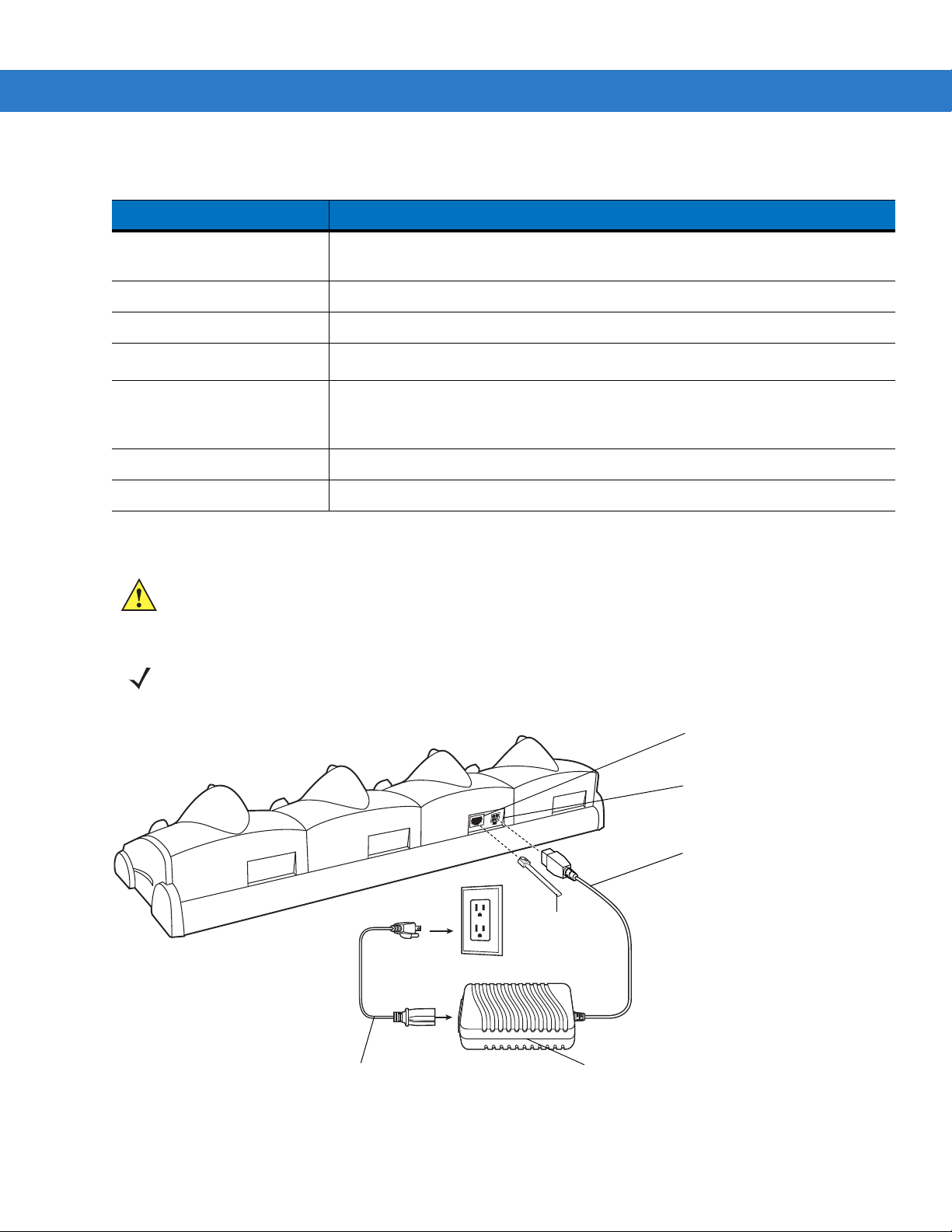
2 - 10 MC909X Integrator Guide
AC Line Cord
Power Supply
DC Cable
To Ethernet
Hub
Power Port
Ethernet
Communication Port
Table 2-2
Communication LED
Status Indication
Off Mobile computer is not in cradle; mobile computer not placed correctly; cradle is
not powered.
Solid Red Mobile computer is present, but communication has not started.
Flashing Green Mobile computer is in the cradle, and communicating with the host computer.
Slow Flashing Red
Error, communication did not start.
Fast Flashing Red Warning: Terminal inactivity time-out. The terminal did not finish data
synchronization or had an open connection for more than 15 minutes. This time is
programmable in the cradle flash parameters.
Solid Green Terminal is present in the slot and communication is complete.
All LEDs Flashing Red Failed automatic cradle configuration via local DHCP Service.
Setup
CAUTION Use only a Symb ol approved power supply output rated 12 VDC and minimum 9 A. Use of an alternative
power supply will void the product warranty and may cause product da mage. Refer to the MC909X User
Guide for the power supply regulatory compliance statement.
Figure 2-9
NOTE The Four Slot Ethernet cradle must be connected to a power source and to an Ethernet Hub (when
applicable).
Four Slot Ethernet Cradle Power Connection

Getting Started 2 - 11
Battery Charging Indicators
The mobile computer’s amber charge LED, located in the Indicator LED Bar, shows the status of the battery
charging in the mobile computer. See Table 1-2 on page 1-8 for charging status indications. The battery usually
charges in less than four hours.
Ethernet Communication Setup
To establish a connection between the mobile computer and the host computer to communicate over an Ethernet
network, perform the following:
•
Install MobileDox Cradle Manager
•
Install iDockIt
•
Configure the mobile computer
•
Configure the host computer
•
Configure the DHCP server
•
Configure the cradle.
Installing MobileDox Cradle Manager
NOTE MobileDox Cradle Manager is used only when establishing a connectio n using the Four Slot Ethernet cradle.
The Cradle Management software features:
•
View cradles that are attached to the network via MobileDox Net
•
View cradle status
•
Modify cradle settings including:
• IP address settings
• DNS and WINS settings
• Identification settings
• USB port specific settings
•
Restart cradles connected to the network via MobileDox Net
Update the firmware of MobileDox Net.
To install the Cradle Management Software on the host computer, download the latest ve rsion of the so f tware from
http://support.symbol.com. Refer to the instructions included with the software.
Installing iDockIt
iDockIt is a connection utility which manages activities between the mobile computer and a connected Ethernet
cradle. For more information on the utility, see the documentation provided with iDockIt.
iDockIt features:
•
The ability to manage multiple cradle profiles. iDockIt auto-detects the cradle communication type and
behaves accordingly.
•
Integrated modem capabilities using TAPI interface.

2 - 12 MC909X Integrator Guide
•
Runs as a tray application, and always runs in the background.
•
The ability to configure settings within the application.
•
Options to change parameters upon docking (with or without settings time-out).
•
The ability to force synchronization events.
•
The ability to disable WLAN connection on the device to ensure synchronization is performed via dock.
•
Management of multiple connection types without losing settings.
On MC909X mobile computers with Windows CE 5.0 or with Windows Mobile 5.0 and OEM version lower than 28,
the iDockIt installation file is To install iDockIt on the mobile computer download the latest version of the iDockIt
software from http://support.symbol.com to the host computer. Follow the instructions provided with the iDockIt
software to install iDockIt onto the mobile computer.
On MC909X mobile computers with OEM version 28 and higher, the iDockIt installation file is loaded on the mobile
computer. To install iDockIt:
1. Open File Explorer.
2. Navigate to the Application directory.
3. Tap th e file: IDOCKIT_4.02.05.2_MC90XX_WM5.cab
iDockIt installs on the mobile computer. Follow the onscreen instruction.
Refer to Appendix B, Using iDockIt for instructions on configuring and using iDockIt.
Mobile Computer Configuration
Inserting the mobile computer into the cradle provides direct-connect Remote Access Service (RAS) service.
Configure each mobile computer for use with the cradle, just as any remote client would be configured to connect
to an Internet Service Provider (ISP). The computer comm port setting was set to USB during the iDockIt
installation procedure.
DHCP Server Configuration
If you use a DHCP server to distribute IP addresses and other network parameters, the server setup should include
the following:
•
IP address pool (1 or 5 IP address per cradle)
•
Router/gateway address
•
One or more DNS server addresses
•
One or more WINS server addresses
•
Subnet mask.
NOTE To assign the initial cradle IP address, you can either use a DHCP server, as shown above, or use the
MobileDox Cradle Manager (see Installing MobileDox Cradle Manager on page 2-11). The DHCP server is
the preferred method.
Cradle Configuration
The MobileDox Cradle Manager allows you to setup the Device IP Address and modify cradle settings. See
Installing MobileDox Cradle Manager on page 2-1 1 for instru ctions to download and inst all the sof tware. See Figure
2-8 on page 2-9 for instructions on Four Slot Ethernet cradle connections.
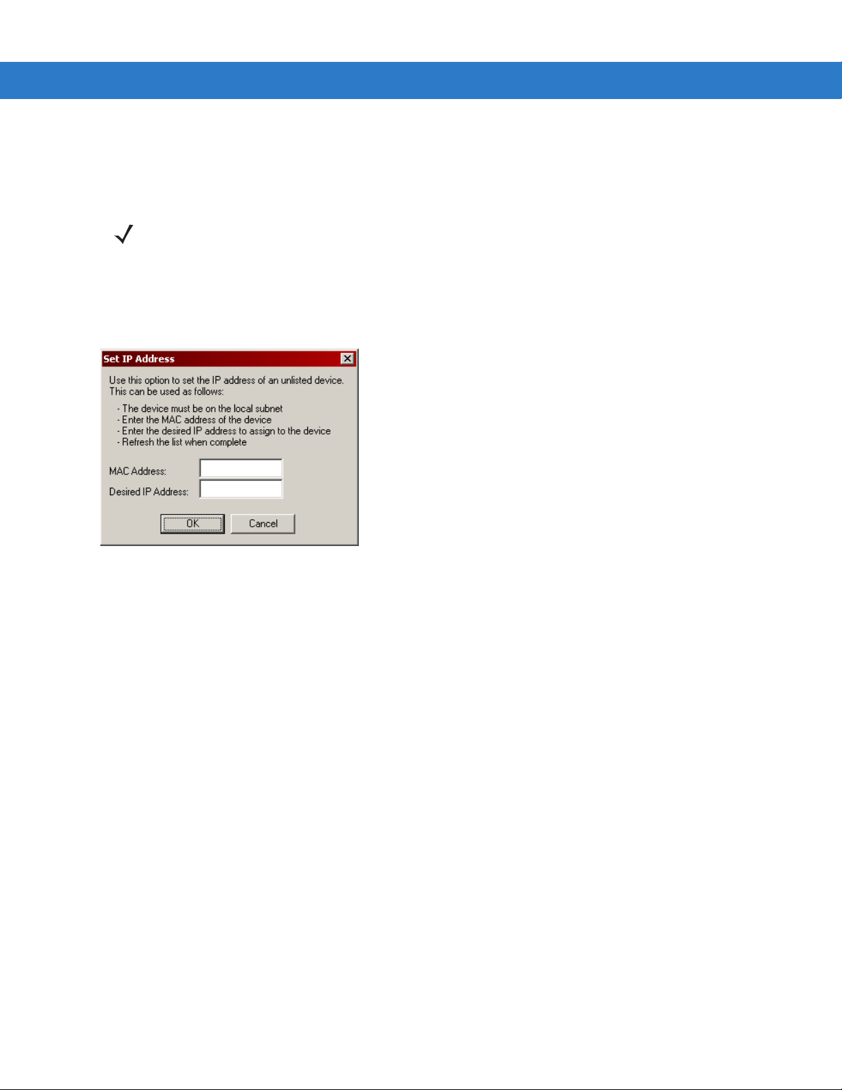
Getting Started 2 - 13
Setting the Device IP Address
By default, the cradle uses DHCP to obtain its IP a ddress. Ho weve r, if DHCP fails, the Cradle Manager can assign
an IP address.
NOTE This is used if the cradle is connected to the network, but fails to appear in MobileDox. Enter the hardware
device (MAC) address to locate the cradle and assign it a new IP address.
To set the IP address:
1. Launch the MobileDox Cradle Manager on the host computer.
2. Click File > Set IP Address of Unlisted Device. The Set IP Address window appears:
Figure 2-10
3. Enter the appropriate MAC Address and IP address.
4. Click OK.
Set IP Address Window
Modifying Cradle Settings
1. Launch the MobileDox Cradle Manager on the host computer.
2. Select the name of the cradle you want to configure from the list.
3. Click Device > Modify Settings.
4. Use the General Settings tab to modify the identification settings of the cradle.
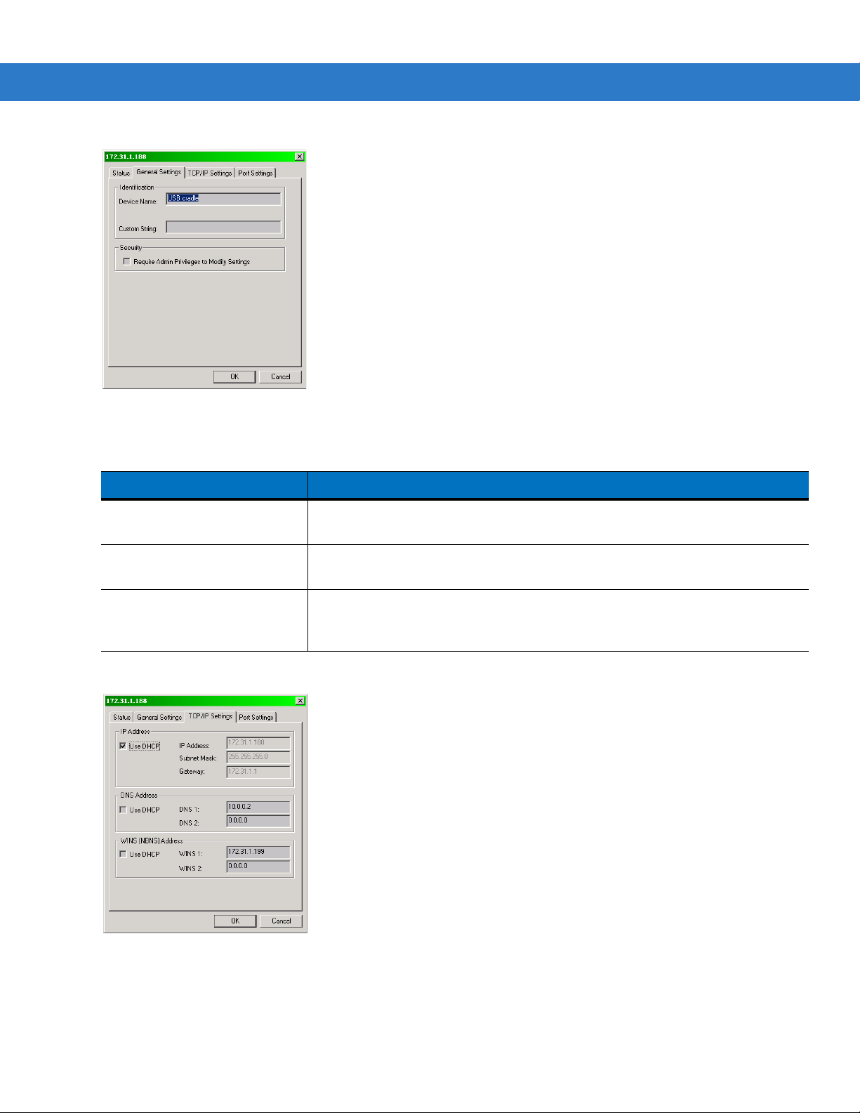
2 - 14 MC909X Integrator Guide
Figure 2-11
Table 2-3
Cradle Settings Window - General Settings Tab
Cradle Settings - General Settings Fields
Field Description
Device Name A text string used to describe the MobileDox device. Any 15-character string may
be entered.
Custom String A text string for any desired usage (examples are: location, asset ID, etc.). Any
15-character string may be entered.
Require Admin Privileges to
Modify Settings check box
Selecting this check box requires users to have administrative privileges in order
to modify MobileDox settings. Administrative privileges are validated using
standard Windows authentication.
5. Use the TPC/IP Settings tab to modify the DNS and WINS identification settings of the cradle.
Figure 2-12
Cradle Settings Window - TCP/IP Settings Tab
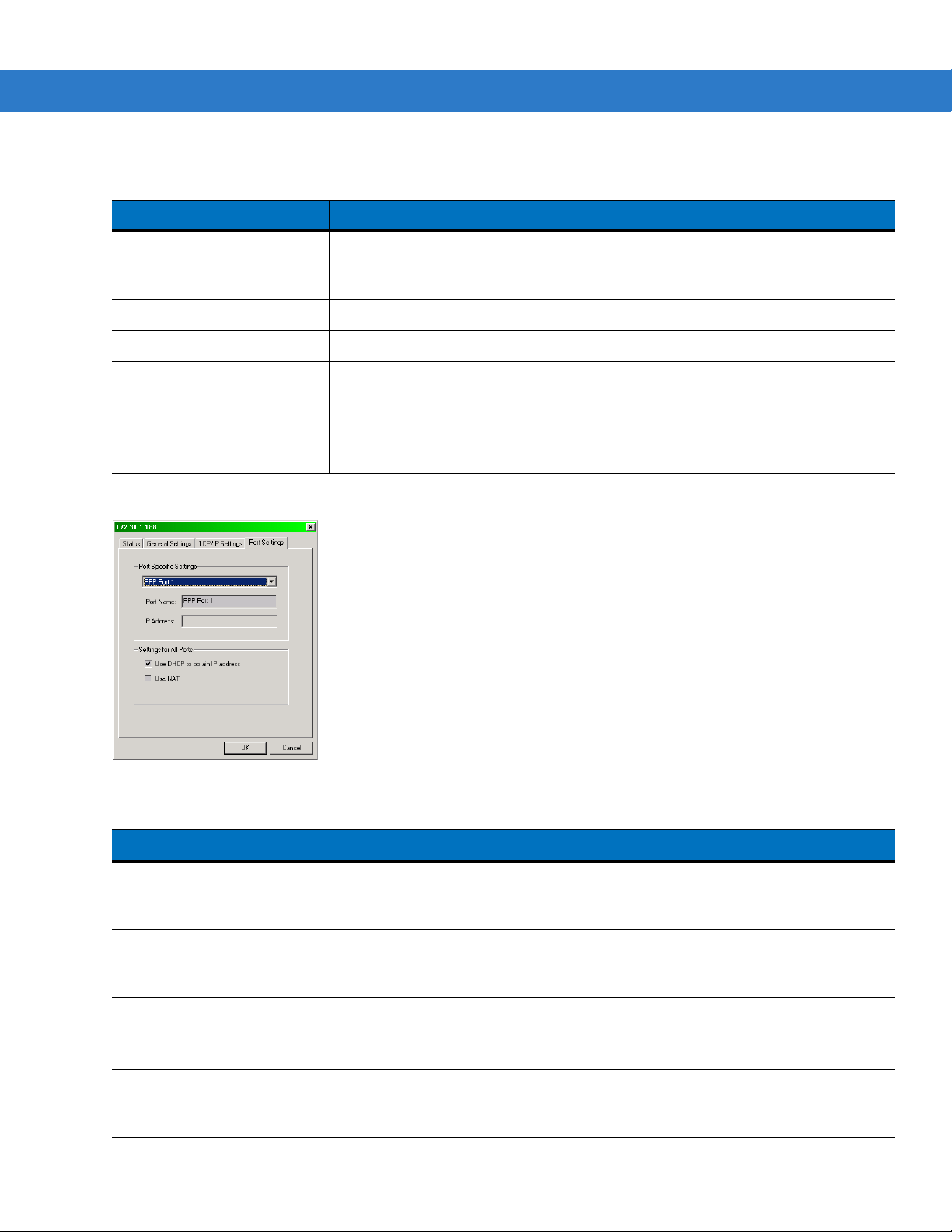
Getting Started 2 - 15
Table 2-4
Cradle Settings - TCP/IP Settings Fields
Field Description
Use DHCP If check box is selected, necessary information is retrieved from the DHCP server.
If check box is not selected, static configuration is used (information needs to be
entered).
IP Address The IP address that the MobileDox uses when communicating on the network.
Subnet Mask The subnet mask that the MobileDox uses when communicating on the network.
Gateway Address The IP address that the MobileDox uses to send non-local IP network data.
DNS Address The IP address of a server(s) that can resolve Internet names into IP addresses.
WINS Address The IP address of a server(s) that can resolve Windows network names into IP
addresses. This field must be populated correctly when using ActiveSync.
6. Use the Port Settings tab to modify the USB port settings of the cradle.
Figure 2-13
Table 2-5
Cradle Settings Window - Port Settings Tab
Cradle Settings - Port Settings Fields
Field Description
Port Name A text string used to describe the device attached to the port. Any 15-character
string can be entered.
You can specify up to four port names, one for each of the cradle’s slots.
IP Address The IP address assigned to the cradled device. There should be one IP address p er
cradle slot. This box is disabled for all devices if DHCP is used to obtain the IP
address.
Use DHCP to obtain IP
Address check box
The cradle uses DHCP to obtain an IP address for the handheld.
Unchecking this selection allows the cradle to use Static IP address for the
handheld.
Use NAT check box The cradle uses Network Address Translation (NAT) when forwarding handheld
traffic onto the network. No IP addresses are necessary for the handhelds. This
must be disable when using ActiveSync.
7. Click OK.

2 - 16 MC909X Integrator Guide
Four Slot Charge Only Cradle
CAUTION Ensure that you follow the guidelines for battery safety described in Battery Safety Guidelines on page
10-1.
This section describes how to set up and use a Four Slot Charge Only cradle with the mobile computer.
Figure 2-14
The Four Slot Charge Only cradle:
•
•
Four Slot Charge Only Cradle
CAUTION Do not place coins, keys or paper clips in cradle well.
Provides 12VDC power for operating the mobile computer.
Simultaneously charges up to four batteries in the mobile computer.

Setup
AC Line Cord
Power Supply
DC Cable
Power Port
Getting Started 2 - 17
CAUTION Use only a Symb ol approved power supply output rated 12 VDC and minimum 9 A. Use of an
alternative power supply will void the product warranty and may cause product damage. Refer to the
MC909X User Guide for the power supply regulatory compliance statement.
Figure 2-15
Four Slot Charge Only Cradle Power Connection
Battery Charging Indicators
The mobile computer’s amber charge LED, located in the Indicator LED Bar, shows the status of the battery
charging in the mobile computer. See Table 1-2 on page 1-8 for charging status indications. The battery usually
charges in less than four hours.

2 - 18 MC909X Integrator Guide
MC909X-S Battery
Spare Battery Charging
LEDs (4)
Spare MC909X-G/K Battery
Short Battery Adapter
Spare Battery Charging Well (4)
Four Slot Spare Battery Charger
CAUTION Ensure that you follow the guidelines for battery safety described in Battery Safety Guidelines on page
10-1.
This section describes how to set up and use the Four Slot Spare Battery Charger to charge up to four spare
batteries.
Figure 2-16
Four Slot Spare Battery Charger

Setup
Power Supply
AC Cord
DC Cable
Power Port
Getting Started 2 - 19
CAUTION Use only a Symb ol approved power supply output rated 15 VDC and minimum 5 A. Use of an alternative
power supply will void the product warranty and may cause product da mage. Refer to the MC909X User
Guide for the power supply regulatory compliance statement.
Figure 2-17
Four Slot Spare Battery Charger Power Connection
Spare Battery Charging with the Four Slot Spare Battery Charger
1. Connect the charger to a power source as shown in Figure 2-17.
2. Insert the battery into a spare battery charging slot and gently press down on the battery to ensure proper
contact.
Battery Charging Indicators
An amber LED is provided on each battery charging well (see Figure 2-16 on page 2-18). See Table 2-6 for
charging status indications.
The battery usually charges in less than four hours.
Table 2-6
Off No spare battery in slot; spare battery not placed correctly; cradle is not powered.
Fast Blinking Amber Error in charging; check placement of spare battery.
Slow Blinking Amber Spare battery is charging.
Solid Amber Charging complete.
Spare Battery LED Charging Indicators
LED Indication

2 - 20 MC909X Integrator Guide
Card Reader Slot
Latches
Power Port
Communications Port
Pogo Pin
Pass-through
Connector
Latch Grip
Magnetic Stripe Reader
This section describes how to set up and use the snap-on MSR with the mobile computer. The MSR snaps on to
the bottom of the mobile computer and can be easily removed when not in use.
Figure 2-18
When attached to the mobile computer, the MSR:
•
•
•
•
•
Magnetic Stripe Reader
Provides power for operating the mobile computer, with the appropriate power connection.
Allows the mobile computer to capture data from magnetic stripe cards. (To download MSR data capture
software, visit: http://support.symbol.com.)
NOTE When a mobile computer with Windows Mobile 5.0 is connected to a host computer through the MSR and
an ActiveSync connection is made, the WLAN and WWAN radios (if applicable) are disabled. This is a
Microsoft security feature to prevent connection to two networks at the same time.
Provides serial connection through the serial pass-through port for communication with a serial device, such
as a host computer. For communication setup procedures, see Serial Communication Setup on page 2-44.
Provides USB connection through the USB pass-through port for communication with a USB device, such as
a host computer. For communication setup procedures, see Serial Communication Setup on page 2-44 .
Charges the mobile computer’s battery, when used with the appropriate power supply.

Attaching and Removing
Latch Grip
(one on each side)
Vehicle Power
Supply
AC Power
Supply
Into Cigarette
Lighter
To attach, snap the MSR onto the bottom of the mobile computer.
Getting Started 2 - 21
Figure 2-19
Attaching the MSR
To remove, squeeze the latch grips and pull the MSR from the mobile computer.
NOTE Remove the MSR from the bottom of the mobile computer before using a cradle for charging and
communication.
Setup
CAUTION Use only a Symbol approved power supply output rated 12 VDC and minimum 3.3 A. Use of an alternative
power supply will void the product warranty and may cause product da mage. Refer to the MC909X User
Guide for the power supply regulatory compliance statement.
Figure 2-20
MSR Power Connection

2 - 22 MC909X Integrator Guide
To Device
Serial/USB
Port
Serial Port
Figure 2-21
MSR Serial/USB Connection
Battery Charging Indicators
To charge the mobile computer’s battery through the MSR, connect the power supply to the MSR (see Figure 2-20
on page 2-21), then attach the MSR to the mobile computer. The mobile computer begins charging automatically.
NOTE Batteries must be charged within the 32° to 104° F (0° to +40° C) ambient temperature range.
The mobile computer’s amber charge LED, located in the Indicator LED Bar, shows the status of the battery
charging in the mobile computer. See Table 1-2 on page 1-8 for charging status indications.
The battery usually charges in less than four hours, if the mobile computer is not in use.
Serial/USB Connection
The MSR can connect to and communicate with a serial/USB device, such as a printer or host computer, through
its serial port. See Serial Communication Setup on page 2-44 for the host computer communication setup
procedure.
To connect the MSR to a serial/USB device, connect one end of the serial device cable into the serial port on the
MSR and the other end into the serial/USB port on the device.
Using the MSR
The MSR9000 sample application is designed to work with the MSR. This sample application illustrates how an
application should handle MSR inputs (refer to the Symbol Application Guide for Symbol Devices).
NOTE The MSR does not need to be attached to the power supply to read magnetic stripes.
To use the MSR:
1. Attach the MSR to the mobile computer (see Attaching and Removing on page 2-21).
2. Power on the mobile computer.
3. Tap Start > 9000 Demo > Test Apps > MSR 9000 or MSR Cameo to start the sample application.

Getting Started 2 - 23
Latches
Power Port
Communications Port
Pogo Pin
Pass-through
Connector
Latch Grip
4. Swipe the magnetic stripe card through the MSR, ensuring the magnetic stripe on the card faces the mobile
computer. The card may be swiped in either direction, from left to right or from right to left. For best results,
gently press down on the card while swiping to ensure contact with the bottom of the reader.
Figure 2-22
Magnetic Stripe Card Swiping
Cable Adapter Module
This section describes how to set up and use the snap-on CAM with the mobile computer. The CAM snaps on to
the bottom of the mobile computer and can be easily removed when not in use.
Figure 2-23
When attached to the mobile computer, the CAM:
Cable Adapter Module
•
Provides power for operating the mobile computer, with the appropriate power connection.
NOTE When a mobile computer with Windows Mobile 5.0 is connected to a host computer through the CAM and an
ActiveSync connection is made, the WLAN and WWAN radios (if applicable) are disabled. This is a Microsoft
security feature to prevent connection to two networks at the same time.

2 - 24 MC909X Integrator Guide
Latch Grip
(one on each side)
OR
Vehicle Power
Supply
AC Power
Supply
Into Cigarette
Lighter
•
Provides serial connection through the serial pass-through port for communication with a serial device, such
as a host computer. For communication setup procedures, see Serial Communication Setup on page 2-44.
•
Provides USB connection through the USB pass-through port for communication with a USB device, such as
a host computer. For communication setup procedures, see Serial Communication Setup on page 2-44 .
•
Charges the mobile computer’s battery, when used with the appropriate power supply.
Attaching and Removing
To attach, snap the CAM onto the bottom of the mobile computer.
Figure 2-24
Attaching the CAM (MC909X-K shown)
To remove, squeeze the latch grips and pull the CAM from the mobile computer.
NOTE Remove the CAM from the bottom of the mobile computer before using a cradle for charging and
communication.
Setup
CAUTION Use only a Symbol approved power supply output rated 12 VDC and minimum 3.3 A. Use of an alternative
power supply will void the product warranty and may cause product da mage. Refer to the MC909X User
Guide for the power supply regulatory compliance statement.
Figure 2-25
CAM Power Connection

Getting Started 2 - 25
Serial Port
To Device
Serial/USB
Port
Figure 2-26
CAM Serial Connection
Battery Charging Indicators
To charge the mobile computer’s battery through the CAM, connect the power supply to the CAM (see Figure 2-25
on page 2-24), then attach the CAM to the mobile computer. The mobile computer begins charging automatically.
NOTE Batteries must be charged within the 32° to 104° F (0° to +40° C) ambient temperature range.
The mobile computer’s amber charge LED, located in the Indicator LED Bar, shows the status of the battery
charging in the mobile computer. See Table 1-2 on page 1-8 for charging status indications. The battery usually
charges in less than four hours, if the mobile computer is not in use.
Serial/USB Connection
The CAM can connect to and communicate with a serial/USB device, such as a printer or host computer, through
its serial port. See Serial Communication Setup on page 2-44 for the host computer communication setup
procedure.
To connect the CAM to a serial/USB device, connect one end of the serial device cable into the serial port on the
CAM and the other end into the serial/USB port on the device.
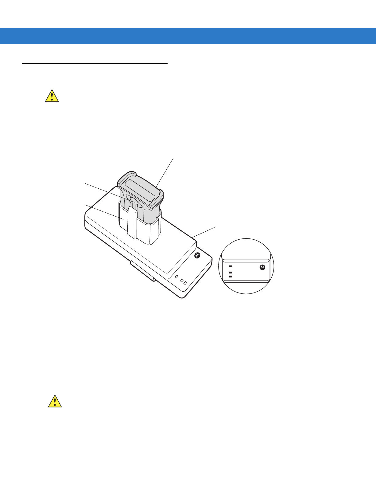
2 - 26 MC909X Integrator Guide
UBC Adapter
Battery Release
Battery
Battery Well
Universal Battery Charger (UBC) Adapter
CAUTION Ensure that you follow the guidelines for battery safety described in Battery Safety Guidelines on page
10-1.
This section describes how to use the UBC adapter to charge a spare battery.
The UBC can be used with a power supply as a standalone spare battery charger or it can be used with the four
station UBC2000 to provide charging to simultaneously charge up to four spare batteries. For additional
information about the UBC2000, see the UBC 2000 Universal Battery Charger Product Guide (p/n 70-33188-xx)
.
Inserting and Removing a Battery
Setup
POWER
READY or STANDBY or FA ULT
(Green) (Flashing Yellow) (Solid Yellow)
CHARGING
(Solid Yellow)
Figure 2-27
Insert the battery into the battery well with the charging cont act s fa cing down (over cha rging pins) and gently press
down on the battery to ensure proper contact.
UBC Adapter
To remove the battery, press the battery release and lift battery out of the well.
CAUTION Use only a Symbol approved power supply output rated 15 VDC and minimum 1.5 A. Use of an alternative
power supply will void the product warranty and may cause product da mage. Refer to the MC909X User
Guide for the power supply regulatory compliance statement.
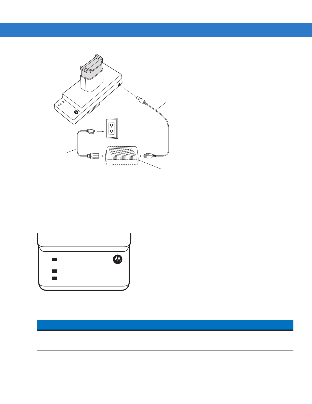
Getting Started 2 - 27
Power Supply
AC Line Cord
DC Cable
POWER
READY or STANDBY or FAULT
CHARGING
(Green) (Flashing Yellow) (Solid Y ellow)
(Solid Yellow)
Figure 2-28
UBC Adapter Power Connection
Battery Charging Indicators
To charge a spare battery using the UBC adapter, connect the power supply to the UBC (see Figure 2-28 on page
2-27), then insert the spare battery . The spare battery begins charging automatically. The UBC’s charge LEDs (see
Figure 2-29)) show the status of the battery charging in the adapter. Table 2-7 shows battery charging status
indications. The battery usually charges in three hours.
Figure 2-29
Table 2-7
POWER Green Power is connected to the UBC Adapter.
UBC Adapter LEDs
UBC Adapter Charge LED Status Indications
LED Indication Description
READY or Green Charging complete.

2 - 28 MC909X Integrator Guide
Serial Port
Line In Port
LEDs
Phone Port
Table 2-7
STANDBY or Flashing-Yellow The battery was deeply discharged and is being trickle charged to bring the
FAULT Yellow Charging error, check placement of mobile computer/spare battery.
CHARGING Yellow Normal charge.
UBC Adapter Charge LED Status Indications (Co ntinued)
LED Indication Description
Modem Module
This section describes how to setup and use the MDM9000 Modem Module.
voltage up to the operating level. After operating level voltage is achieved the
battery charges normally.
Figure 2-30
The Modem Module enables data communication between the mobile computer and a host computer, remotely
through the phone lines, and synchronizes information between the mobile computer and a host computer.
The following items are required for a modem conn ect ion :
•
•
•
•
The following items are required for communication:
•
•
•
•
Modem Module
Telephone number, IP address and DNS/WINS address information from the dial-in server administrator
Dial-in account on the host system, including a user ID and password
RJ1 1 or RJ12 modem cable
Functioning telephone jack that supports plug-in modems connected to the local telephone system
Setup of Country Codes to use the modem with the appropriate country’s telephone network.
MC909X mobile computer
Cable Adapter Module (CAM), Symbol p/n ADP9000-100 (see Cable Adapter Module on page 2-23)
Serial Adapter Cable (for communication via cradle), Symbol p/n 25-63856-01
Microsoft ActiveSync
Setup of host computer and mobile computer.
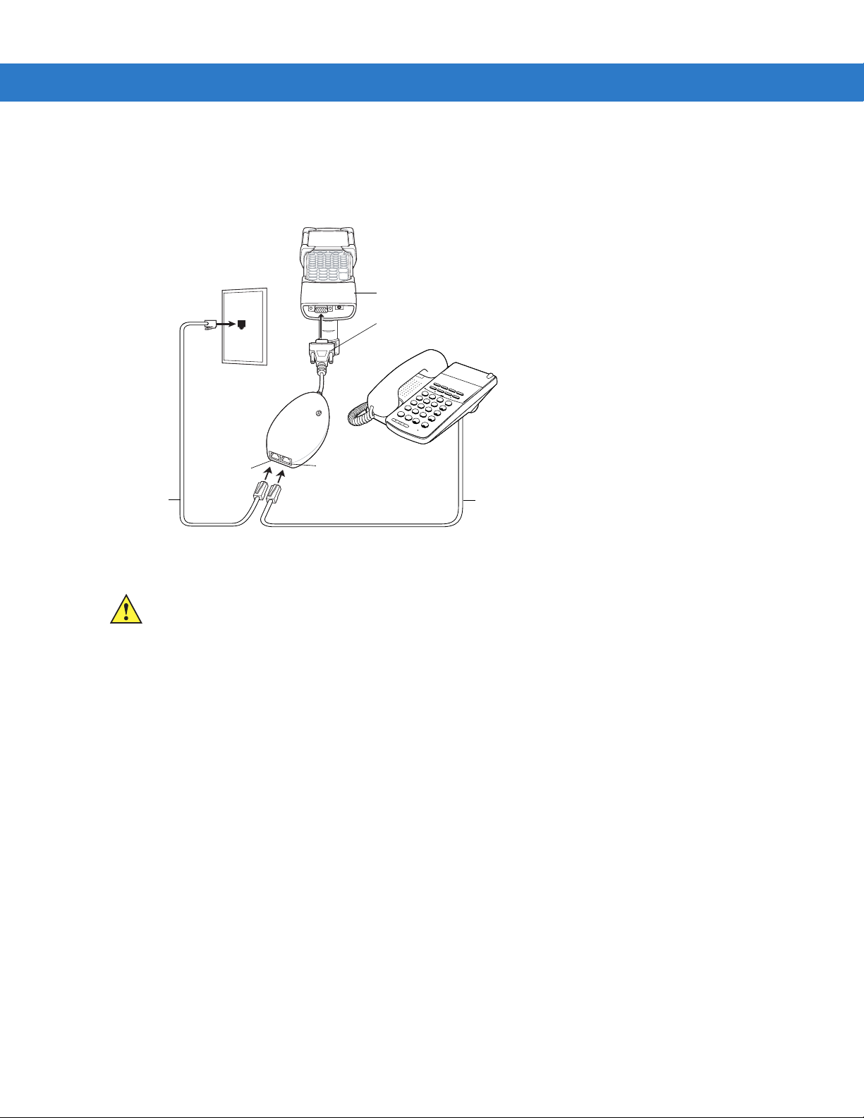
Setup
CAM
Male 15-pin
connector
Phone cord
Line In port
Phone cord
Phone port
Connecting to the Mobile Computer
Getting Started 2 - 29
1
2
A
B
4
C
G
H
I
3
D
E
5
F
J
K
7
L
R
E
C
P
A
R
L
S
6
L
M
NO
8
T
UV
F
N
C
9
W
*
X
Y
0
O
P
C
E
N
R
F
H
O
L
D
#
L
NR
TRF
S
P
D
A
NS
S
P
KR
Figure 2-31
Modem Module Connection - Mobile Computer
CAUTION Do not connect the modem's 15-pin connector into a VGA port of a host computer.
Using the Correct Telephone Line Type
Use a standard analog phone line, as in most households. In an office, use a line connected to a fax machine or
modem. In a hotel, request a room with a stand ard phone line o r data port. If necessary, check with the local phone
company or administrator to make sure you are using the right type of line before sending data.
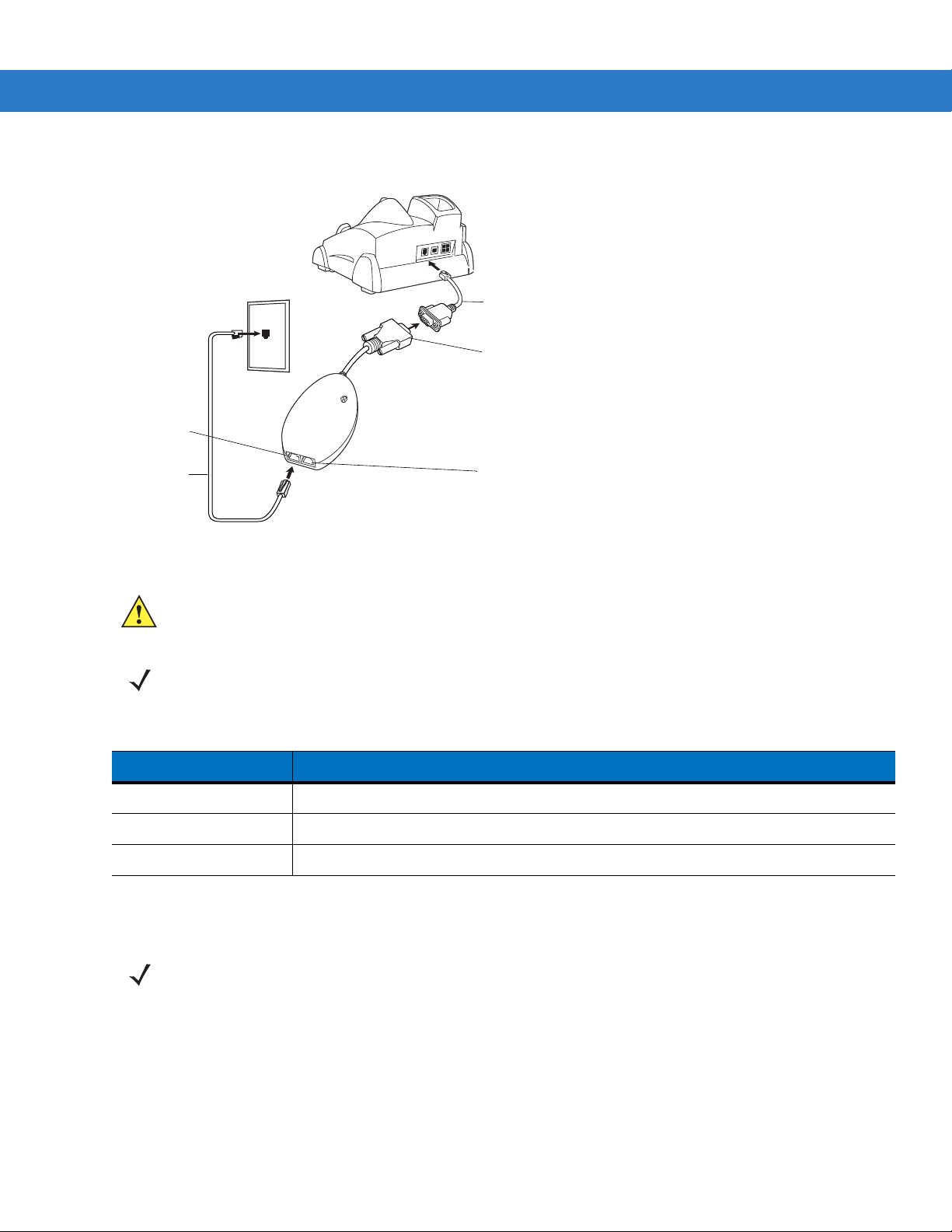
2 - 30 MC909X Integrator Guide
Adapter cable
Phone cord
Male 15-pin connector
Line In port
Phone port
Connecting to the Single Slot Serial/USB Cradle
Figure 2-32
Table 2-8
Modem Module Connection - Single Slot Serial/USB Cradle
CAUTION Do not connect the modem's 15-pin connector into a VGA port of a host computer.
NOTE If using a phone, connect the cord from the phone to the Phone port on the modem.
Modem Indicators
LED Indication
Off Modem is not properly connected to the mobile computer; modem is not receiving power.
Green Modem is connected to the mobile computer and is receiving power.
Solid Amber Mobile computer is communicating with the host computer.
Configuring the Mobile Computer for the Modem (Windows Mobile 5.0)
NOTE To edit an existing modem connection using Manage existing connections, see Changing the Initialization
String (Windows Mobile 2005) on page 2-36.
To create a new modem connection on the mobile computer:
1. Connect the modem to the mobile computer as described in Connecting to the M obile Computer on p ag e 2-29.
2. Tap Start > Settings > Connections tab > Connections icon.
3. In the Connections window, select Add a new modem connection to create a connection.
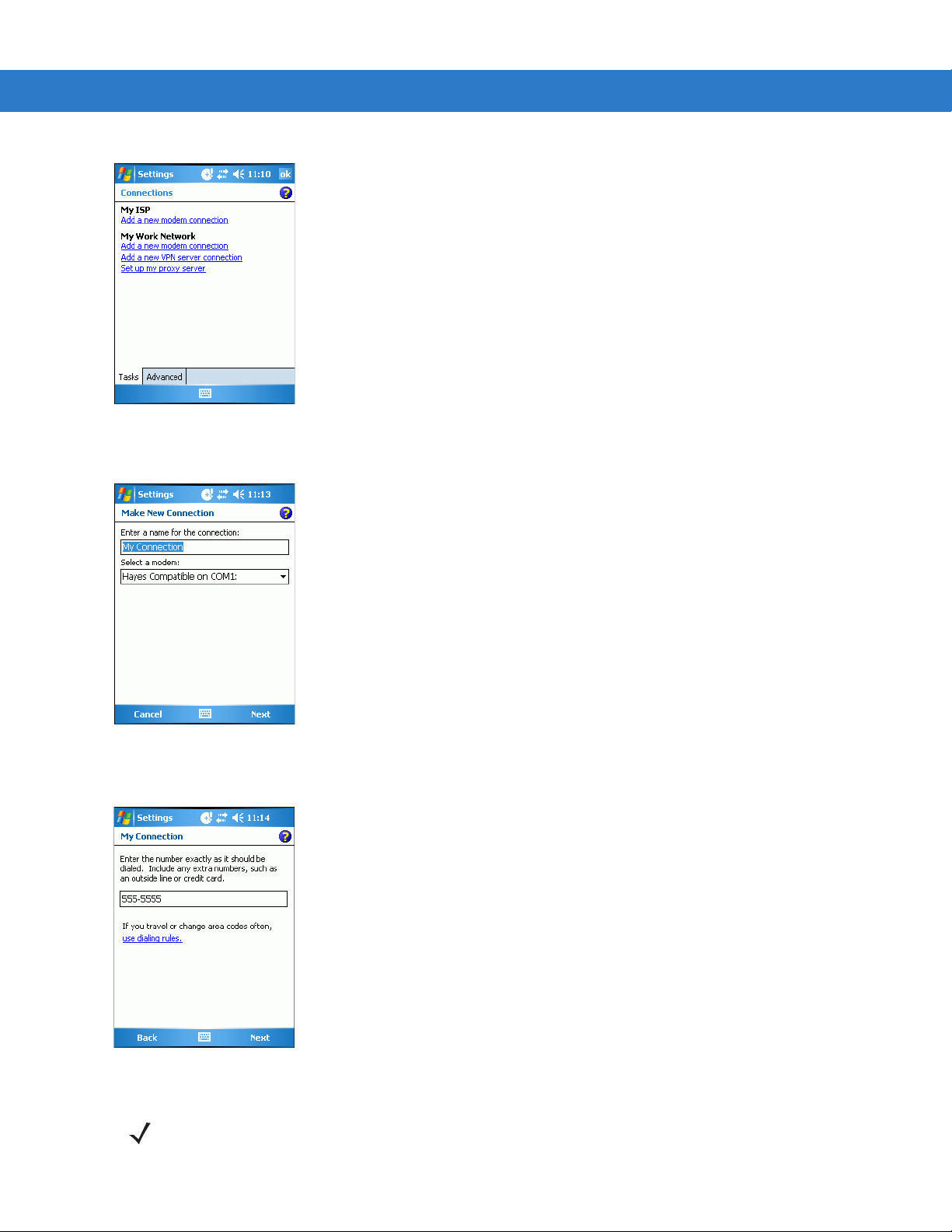
Getting Started 2 - 31
Figure 2-33
4. Enter a name for the connection. In the drop-down menu, select Hayes Compatible on COM1, then tap Next.
Figure 2-34
5. Enter the access phone number in the My Connection window and tap Next.
Connections Window
New Connection Window
Figure 2-35
NOTE Depending on the location when dialing, additional numbers may need to be dialed (e.g., a 9 prefix is often
My Connection Window - Phone Number
required if dialing from work; a country code is needed if dialing internationally). To avoid creating new modem
connections for each situation, tap use dialing rules to define frequently used dialing locations.

2 - 32 MC909X Integrator Guide
6. If necessary, enter the user name, password and domain.
Figure 2-36
7. Tap Advanced... to edit the Extra dial-string modem commands: text box to set country parameters to operate
My Connection Window - User Information Settings
the modem with other country telephone networks.
Figure 2-37
Advanced Window - Extra Dial-String Modem Commands
The modem defaults to operation with US telephone networks (country code: B5). To operate the modem with
other country telephone networks, a country code must be entered. The modem adjusts its operating
parameters to comply with the telephone network in the country specified. See Modem Country Setup on page
2-35 for the appropriate syntax and a list of country codes.
8. Tap ok to exit the Advanced window.
9. Tap Finish.
Configuring the Mobile Computer for the Modem (Windows CE 5.0)
To create a modem connection on the mobile computer:
1. Connect the modem to the mobile computer, see Connecting to the Mobile Computer on page 2-29.
2. On the MC909X, tap Settings > Control Panel. Double-tap the Network and Dial-up Connections icon.
3. In the Connection window, double-tap Make New Connection to create a connection.

Getting Started 2 - 33
Figure 2-38
4. Enter a name for the connection on the Make New Connection window, then tap Next.
5. In the Select a modem list, select Hayes Compatible on COM1, then tap Next.
Figure 2-39
6. In the Phone Number window, enter the phone number for the connection, then tap Finish.
Network and Connections Windows
New Connection and Modem Windows
Figure 2-40
NOTE Depending on the location when dialing, additional numbers may need to be dialed (e.g., a 9 prefix is often
Phone Number Window
required if dialing from work; a country code is needed if dialing internationally). To avoid creating new modem
connections for each situation, tap use dialing rules to define frequently used dialin g locations.
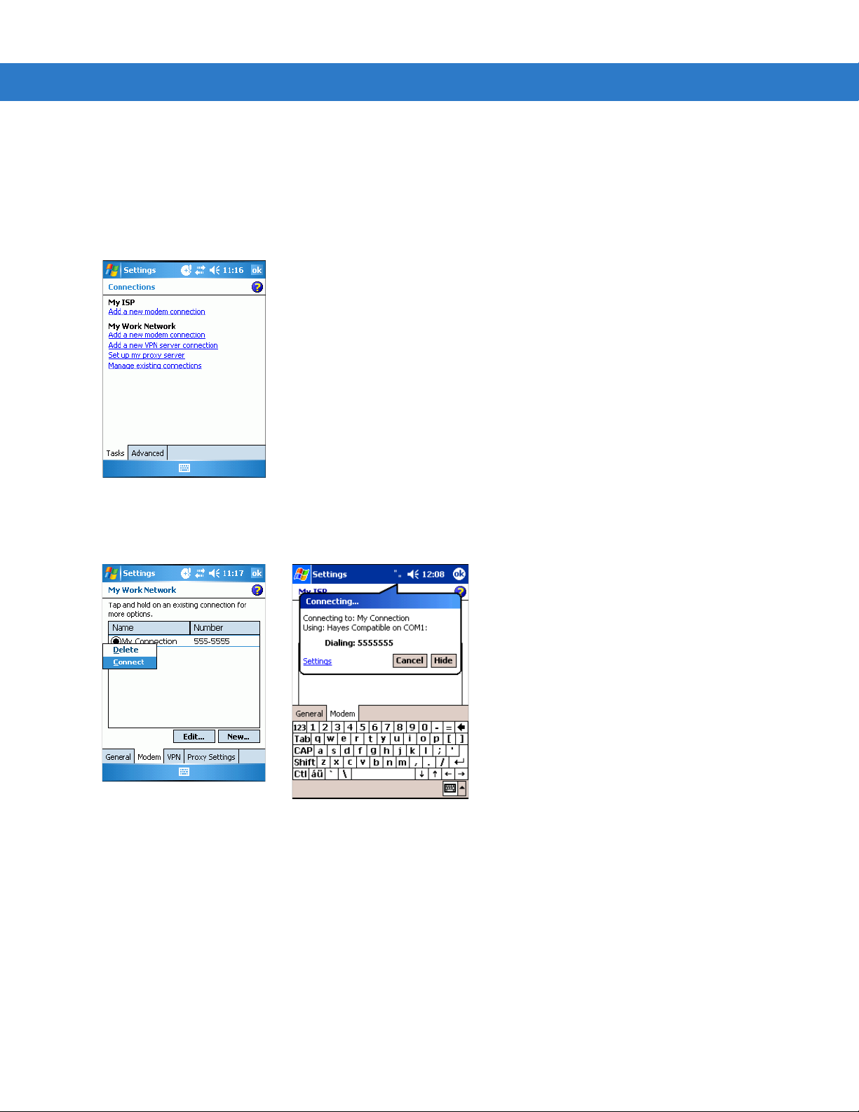
2 - 34 MC909X Integrator Guide
Connecting the Modem (Windows Mobile 5.0)
To start the connection:
1. Tap Start > Settings > Connections tab > Connections.
2. In the Connections window, tap Manage existing connections.
Figure 2-41
3. Tap and hold the connection name, then select Connect from the menu that appears. The modem attempts to
My Connections Window
connect.
Figure 2-42
Creating a Connection
Connecting the Modem (Windows CE 5.0)
To connect to the host computer using the modem connection created in the last section:
1. Tap Start > Settings > Control Panel. Double-tap the Network and Dialup Connections icon.
2. In the Connection window, double-t ap the name of the connection create d in Creating a Connecting the Modem
(Windows CE 5.0) on page 2-34.
3. To modify dial-up properties, tap Dial Properties..., make the selections in the Device Properties window, then
tap
OK.
4. Tap Connect. The modem attempts to connect.

Getting Started 2 - 35
Figure 2-43
Dial-Up and Dial Properties Window
Modem Country Setup
Edit the Extra dial-string modem commands: text box in the mobile computer to set co untry p arameters. Th e synta x
used is: +GCI=<country_code>.
Supported Countries
Table 2-9
Australia 09 Greece FD or 46 Norway FD or 82
Austria FD or 0A Iceland FD Portugal FD or 8B
Belgium FD or 0F Ireland FD or 57 Spain FD or A0
Brazil 16 Italy FD or 59 Sweden FD or A5
Canada 20 Liechtenstein FD Switzerland FD or A6
Denmark FD or 31 Luxembourg FD TBR-21 (Europe) FD
Finland FD or 3C Mexico 73 United Kingdom FD or B4
Supported Countries
Country Code Country Code Country Code
France FD or 3D Netherlands FD or 7B United States B5 (Default)
Germany FD or 42 New Zealand 7E
Note:
Use FD where possible. If connection problems occur, use the alternate code where provided.
AT Commands
The AT Command Set allows you to custom-configure the modem.
NOTE Only experienced users having difficulty with default settings should use this feature.

2 - 36 MC909X Integrator Guide
Changing the Initialization String (Windows Mobile 2005)
To enter AT commands:
1. Tap Start > Settings > Connections tab > Connections icon.
2. If creating a new connection, select Add a new modem connection in the Connections window. Then follow
steps 1 through 6 in Configuring the Mobile Computer for the Modem (Windows Mobile 5.0) on page 2-30 and
proceed to step 6.
.
Figure 2-44
3. If entering AT commands for an existing connection, select Manage existing connections in the Connections
Connections Window
window.
4. On the Modem tab, select the radio button of the item to edit and tap Edit... .
Figure 2-45
5. Tap Next until the User Information Settings window appears.
6. Tap Advanced... .
New Connection Window

Getting Started 2 - 37
Figure 2-46
7. Enter AT commands in the Extra dial-string modem commands: text box. See Basic AT Command Syntax on
My Connection Window - User Information Settings
page 2-39.
Figure 2-47
8. Tap ok to exit the Advanced window.
9. Tap Finish.
Advanced Window - Extra Dial-String Modem Commands
Changing the Initialization String (Windows CE 5.0)
To enter AT commands:
1. On the mobile computer, tap Settings >Control Panel. Double-tap the Network and Dial-up Connections icon.
2. In the Connection window, double-tap the My Connection icon to edit the settings.

2 - 38 MC909X Integrator Guide
Figure 2-48
3. To modify dial-up properties, tap Dial Properties, make the selections in the Device Properties window.
4. To edit the Dialing Patterns, tap Edit.
Figure 2-49
5. The Edit Dialing Patterns window appears.
Network and Connections Windows
Dial-Up and Dial Properties Window
Figure 2-50
6. Edit the dialing properties, see Table 2-10 on page 2-40.
7. Tap OK to exit the Edit Dialing Patterns window.
8. Tap OK to exit the Dialing Patterns window.
9. Tap Connect at the Dial-Up Connection window. The modem attempts to connect.
Edit Dialing Patterns Window

Getting Started 2 - 39
Basic AT Command Syntax
A command line is made up of three elements:
•
Prefix - consists of the characters “AT” or “at” or, to repeat the execution of the previous command line, “A/”
or “a/”.
•
Body - made up of individual commands described later. Space characters (IA5 2/0) are ignored and may be
used for formatting purposes, unless they are embedded in numeric or string constants. The termination
character may not appear in the body. The modem can accept at least 40 characters in the body.
•
Termination character - may be selected by a user option (parameter S3). The default is CR.
The format of Basic Syntax commands, except for the D and S commands, is as follows:
<command>[<number>]
where:
•
<command> is either a single character, or the “&” character followed by a single char acter p er V.250; or the
“%” character followed by a single character, the “*” character followed by a single character, or the “^”
character followed by a single character.
•
<number> is a string of one or more characters from “0” through “9” representing a decimal integer value.
Commands expecting a <number> are noted in the descr iption of the command. If <number> is missing from
such a command (<command> is immediately followed by another <command> or the termination
character), the value “0” is assumed. If a command does not expect a <number> and a number is present, an
error occurs. All leading “0”s in <number> are ignored by the modem.
Additional commands may follow a command (and associat ed parameter, if any) on the same command line with a
separation character. The actions of some commands cause the rest of the command line to be ignored.
S-Parameters
Commands that begin with the letter “S” are known as “S-parameters”. The number following the “S” indicates the
“parameter number” referenced. If the number is not recognized as a valid p arameter number, an ERROR result
code issues. Immediately following this number, either a “?” or “=” character must appear. “?” is used to read the
current value of the indicated S-parameter; “=” sets the S-parameter to a new value.
S<parameter_number>?
S<parameter_number>=[<value>]
If the “=” is used, the new value to be stor ed in the S-p ara meter is specified in decimal following the “=”. If no value
is given (i.e., the end of the command line occurs or the next command follows immediately), the S-parameter
specified may be set to 0, or an ERROR result code issues and the stored value remains. The ranges of
acceptable values are given in the description of each S-parameter.
If the “?” is used, the modem transmits a single line of information text to the DTE. The text portion of this
information text consists of exactly three characters, giving the value of the S-parameter in decimal, with leading
zeroes included.

2 - 40 MC909X Integrator Guide
Commands
The tables that follow summarize the AT commands, result codes, and S-Registers for the MDM 3000. <string>
represents a letter, number, or symbol to be entered. <val ue> repr esent s a num ber to be e ntered. Possible val ues
are listed below the command.
Table 2-10
Command Description
D Dial “D<string>”
AT Command Table
0-9 DTMF digits 0-9
* The ‘star’ digit (tone dialing only)
# The ‘gate’ digit (tone dialing only)
A-D DTMF digits A,B,C,D X
L Re-dial last number
P Pulse dialing X
T Tone dialing
W Wait for dial tone. (Modem waits for dial tone before dialing digits
following “W”.)
@ Wait for silence. (Modem waits for at least 5 seconds of silence in the
call progress
frequency band before continuing with next dial string parameter.)
& Wait for credit card dialing tone before continuing with the dial string.
Country
Specific
‘ Dial pause. (Modem pauses for a time specified by S8 before dialing
the digits following “,”)
; Return to command state. (Modem goes off hook and allows entering
additional AT commands. Use “H” to go back to on hook.)
() -
<space>
A Off-hook and attempt to answer a call
H Disconnect – Hang UP
O Return to On-Line Data Mode. O <value>
0 Enters on-line data mode without a retrain.
1 Enters on-line data mode with a retrain.
L Speaker volume (Not used)
M Speaker control. M <value>
0 Always off.
1 On during call establishment. Off when receiving carrier. (default)
Ignored. (Might be used to format the dial string.)

Getting Started 2 - 41
Table 2-10
Command Description
&G Guard tone. &G<value> X
&V1 Displays last connection statistics
+MS Modulation Selection. +MS=<carrier> X
AT Command Table (Continued)
2 Always on.
3 Off when receiving carrier and during dialing. On during answering.
0 Disables guard tone. (default)
1 Disables guard tone.
2 Select 1800 Hz guard tone.
B103 Bell 103 (300)
B212 Bell 212 (1200 Rx/75 or 75Rx/1200 Tx)
V21 300
V22 1200
V22B 2400 or 1200
Country
Specific
V23C 1200
V32 9600 or 4800
V32B 14400, 12000, 9600, 7200 or 4800
V34 33600, 31200, 28800, 26400, 2400, 21600, 19200, 16800, 14400,
12000, 9600, 7200, 4800 or 2400
%E Enable/Disable Line Quality Monitor and Auto-Retrain or Fall back/Fall
forward. %E<value>
0 Disable line quality monitor and auto re-train.
1 Enable line quality monitor and auto re-train.
2 Enable line quality monitor and fallback/fall forward. (default).
B CCITT or Bell. B<value>
0 Select CCITT operation at 300 or 1200 bauds.
1 Selects Bell operation at 300 or 1200 bauds.
&L Leased Line Operation. &L<value>
0 Requests dial-up operation. Dial-up operation continues.

2 - 42 MC909X Integrator Guide
Table 2-11
Reg Function Range
S0 Rings to Auto Answer 0-255 0 * rings
S1 Ring Counter 0-255 0 * rings
S2 Escape Character 0-255 43 ASCII
S3 Carriage Return Character 0-127 13 ASCII
S4 Line Feed Character 0-127 10 ASCII
S5 Backspace Character 0-255 8 ASCII
S6 Wait Time before Blind Dialing or Dial Tone 2-255 2 * S
S7 Wait Time for Carrier, Silence or Dial Tone 1-255 50 * S
S8 Pause Time for Dial Delay Modifier 0-255 2 * S
S9 Carrier Detect Response Time 1-255 6 * 0.1 S
S10 Lost Carrier to Hangup Delay 1-255 14 * 0.1 S
S11 DTMF Tone Duration 50-255 95 * mS
S-Register Settings
Default
Default Saved
Units
S12 Escape Prompt Delay (EPD) 0-255 50 * .02 S
S14 General Bit Mapped Options Status - 138 (8Ah)
S16 Test Mode Bit Mapped Options Status - 0
S19 Reserved - 0
S20 Reserved - 0
S21 V.24 Bit Mapped Options Status - 52 (34h)
S22 Speaker/Results Bit Mapped Options - 117 (75h)
S23 General Bit Mapped Options Status - 62 (3Dh)
S24 Sleep Inactivity Timer 0-255 0 S
S25 Delay to DTR off 0-255 5 S
S26 RTS-to-CTS Delay 0-255 1 .01 S
S27 General Bit Mapped Options Status - 73 (49h)
S28 General Bit Mapped Options Status - 0
S29 Flash Dial Modifier Time 0-255 70 10 mS
S30 Disconnect Inactivity Timer 0-255 0 10 S
* Register value may be stored in on of two user
** Country-dependent

Getting Started 2 - 43
Table 2-11
Reg Function Range
S31 General Bit Mapped Options Status - 195 (C0h)
S36 LAPM Failure Control - 7 *
S38 Delay Before Forced Hangup 0-255 20 S
S39 Flow Control Bit Mapped Options Status - 3
S40 General Bit Mapped Options Status - 104 (68h) *
S41 General Bit Mapped Options Status - 195 (C3h) *
S46 Data Compression Control - 138 *
S48 V.42 Negotiation Control - 7
S86 Call Failure Indication 0-26 0
S91 PSTN Transmit Attenuation Level 0-15 10** dBm
S92 Fax Transmit Attenuation Level 0-15 10** dBm
S95 Extended Result Codes Control 0 *
S-Register Settings (Continued)
Default
Default Saved
Units
S210 V.34 Symbol Rate 0-255 13 (0Dh)
* Register value may be stored in on of two user
** Country-dependent

2 - 44 MC909X Integrator Guide
Serial Communication Setup
The serial communications setup can be used to set up to communicate with a Single Slot Serial/USB Cradle, MSR
or a CAM.
NOTE For serial communication using accessories that can communicate with either a serial or USB connection,
connect only the serial cable. Do not connect both the serial and USB cables. If both serial and USB
communication cables are required, the host computer’s USB port must be disabled in ActiveSync befo re
serial communication can be enabled.
Setting Up a Connection on the Mobile Computer
1. On the mobile computer tap Start > Programs > ActiveSync to display the ActiveSync window.
Figure 2-51
2. Tap Menu > Connections. The Connections window appears.
ActiveSync Window
(Windows Mobile 2005)
Figure 2-52
3. Select the Synchronize all PCs using this connection: check box.
4. Select the connection (e.g., serial COM port, Bluetooth, or USB) for synchronization from the drop-down list.
The default connection for synchronization is USB.
5. Tap ok to exit the Connections window.
Connections Window
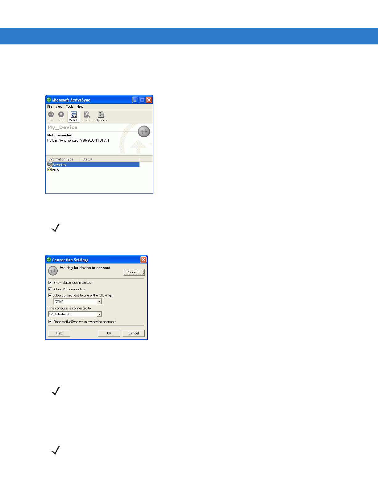
Getting Started 2 - 45
6. Ensure that ActiveSync is installed on the host computer and a partnership was created.
7. Select Start > Programs > Microsoft ActiveSync on the host computer, if it is not already running. The Microsoft
ActiveSync
window appears.
Figure 2-53
8. In the ActiveSync window, select File > Connection Settings. The Connection Settings window appears.
Figure 2-54
9. In the Connection Settings window, select the appropriate check box for the type of connection being used. If
ActiveSync - Not Connected
NOTE Every mobile computer should have a unique device name. Never try to synchronize more than one
mobile computer to the same name.
Connection Settings Window
using a serial connection, select the COM port from the drop-down list.
NOTE If serial, USB and Ethernet communication connections are used, all check boxes can be selected to avoid
having to update this window for different connections.
10. Tap OK to save any changes made.
11. Ensure the accessory being used to communicate is connected to the host computer and the appropriate
power source.
NOTE The accessory requires a dedicated port. It cannot share a port with any other device. Refer to the host
computer user manual supplied to locate the USB ports.
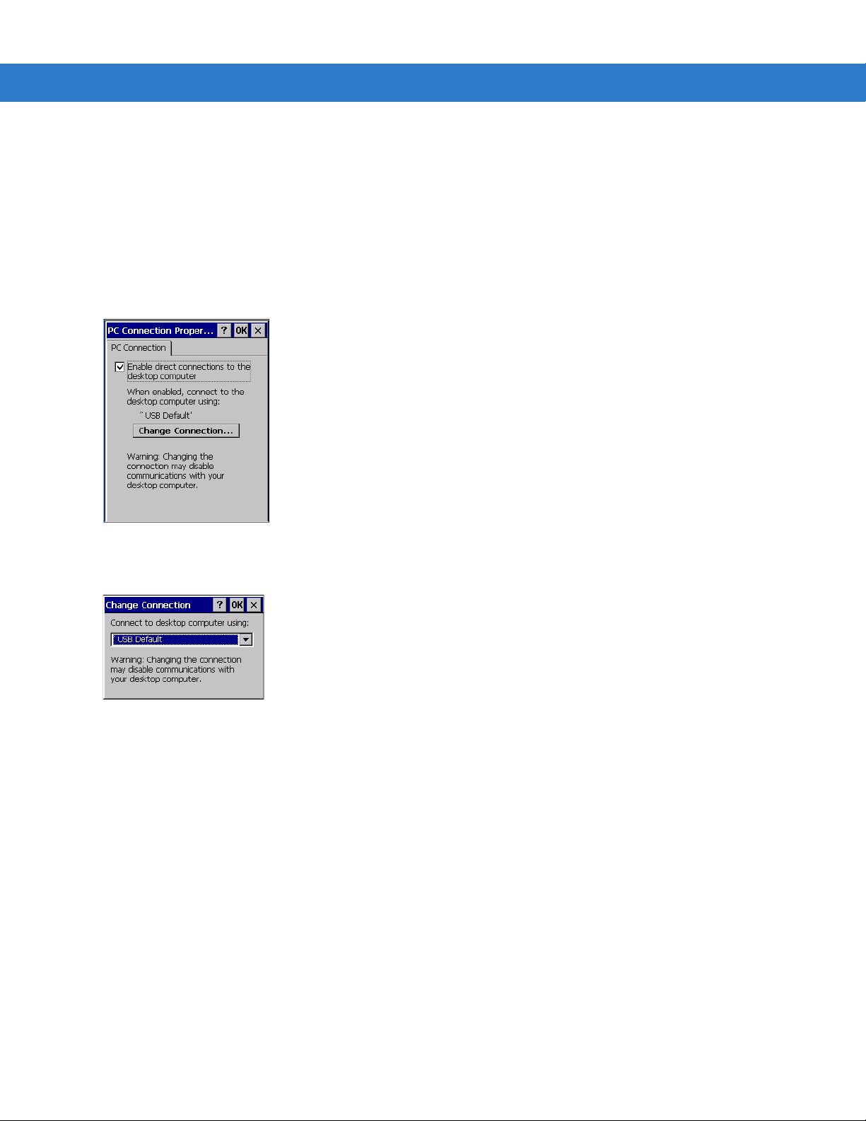
2 - 46 MC909X Integrator Guide
12. Connect the mobile computer to the accessory being used for communication.
13. Power on the mobile computer.
14. If a partnership was already created between the host computer and mobile compu ter, synchronization occurs
automatically upon connection.
Serial Connection Setup (Windows CE 5.0)
1. On the mobile computer tap Start > Settings > Control Panel > PC Connection icon.
Figure 2-55
2. Tap Change Connection... .
Figure 2-56
3. Select the serial communication type from the drop-down list.
4. Tap OK.
5. Tap OK.
6. Ensure that ActiveSync was installed on the host computer and a partnership was created.
7. Start ActiveSync if it is not running on the host computer. To start, select Start > Programs > Microsoft
ActiveSync
PC Connection Properties Window
Change Connection Window
.
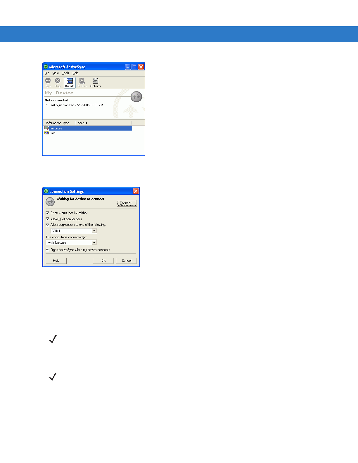
Getting Started 2 - 47
Figure 2-57
8. In the ActiveSync window, select File > Connection Settings. The Connection Settings window displays.
Figure 2-58
9. For a serial connection, select Allow connections to one of the following: check box and select the comm port
ActiveSync - Not Connected
Connection Settings
from the drop-down list.
10. For USB connection, select Allow USB connection check box.
11. Tap OK to save any changes made.
NOTE Every mobile computer should have a unique device name. Never try to synchronize more than one mobile
computer to the same name.
12. Connect the device to the host computer.
NOTE The cradle requires a dedicated port. It cannot share a port with an internal modem or other device. Refer to
the computer user manual supplied to locate the serial port(s).
13. Upon connection, synchronization occurs automatically.

2 - 48 MC909X Integrator Guide
USB Host Communication Setup
NOTE USB Host mode is only available on Windows Mobile 5.0 devices.
The mobile computer can be configured as a USB host device for use with USB client devices.
To configure the mobile computer as a USB host:
1. Tap Start > Settings > System > USBConfig icon.
Figure 2-59
2. Tap th e USB Host Mode radio button.
3. Tap OK.
USBConfig Settings Window
NOTE When the mobile computer is configured a a USB host, it cannot ActiveSync with a host computer.
To configure the mobile computer as a USB client:
1. Tap Start > Settings > System > USBConfig icon.
2. Tap th e USB Client Mode radio button.
3. Tap OK.
4. Remove the mobile computer from the cradle or CAM.
5. Re-insert the mobile computer into a cradle or re-connect the CAM.

Wall Mounting Bracket and Shelf Slide
Wall Mounting
Bracket
Shelf Slides
Mounts two single slot cradlesMounts one single slot cradle
This section describes how to install and set up the MC9000 Wall Mount Bracket and Shelf Slide to mount cradles
to a wall.
Getting Started 2 - 49
Figure 2-60
When installed on a wall, the mounting bracket and shelf slide enable mounting one or two single slot cradles to a
wall. Use two brackets to mount a four slot cradle.
Figure 2-61
Wall Mounting Bracket with Shelf Slide
Mounted Single Slot Cradle With Power Connection
Installing the Wall Mount Bracket
To install the wall mount bracket for use with one or two single slot cradles or four slot chargers, place the smaller
surface of the bracket against the wall or vertical support structur e, and secure with four 1/4” screws (use two of the
three screw holes in each row).

2 - 50 MC909X Integrator Guide
Insert screws
Insert screws
Insert screws from below
Pan-head Screw Holes
Figure 2-62
Wall Mounting Bracket Mounting Screws
If using the bracket and slide with a four slot cradle, secure a second bracket to the wall next to the first, aligning
the horizontal screw holes on the second with those of the firs t.
Attaching the Shelf Slide to the Wall Mount Bracket
One Single Slot Cradle/Four Slot Battery Charger
To attach the shelf slide to the wall mount bracket for use with one single slot cradle or four slot battery charger:
1. Place the slide on the bracket, aligning the larger pan-head screw holes in the slide with the center two screw
holes on the bracket.
2. Secure the slide to the bracket by inserting the two pan-head screws provided from below the bracket, up
through the bracket’s screw holes and then through the slide’s pan-head screw holes.
Figure 2-63
Two Single Slot Cradles/Four Slot Battery Chargers
To attach the shelf slide to the wall mount bracket for use with two single slot cradles or two four slot battery
chargers:
1. Place the slide on the bracket, aligning the larger pan-head screw holes in the slide with the left or right two
2. Secure the slide to the bracket by inserting the two pan-head screws provided from below the bracket, up
3. Secure a second slide to the remaining two screw holes on the bracket in the same manner.
Attaching One Shelf Slide
screw holes on the bracket.
through the bracket’s screw holes and then through the slide’s pan-head screw holes.

Getting Started 2 - 51
Insert screws from below
Pan-head
screw holes
Slide grooves on bottom of
cradle/charger over bracket slide
Figure 2-64
Attaching Two Shelf Slides
Four Slot Cradle
To attach the shelf slide to the wall mount bracket for use with a four slot cradle:
1. Place a slide on the left-hand bracket, aligning the larger pan-head screw holes in the slide with the left two
screw holes on the bracket.
2. Secure the slide to the bracket by inserting the two pan-head screws provided from below the bracket, up
through the bracket’s screw holes and then through the slide’s pan-head screw holes.
3. Place a slide on the right-hand bracket, aligning the larger pan-head screw holes in the slide with the right two
screw holes on the bracket.
4. Secure the second slide to the bracket as described in Step 2.
Installing the Cradle/Charger on the Bracket
Install the cradle or charger onto the bracket, inserting the bracket’s slide into the grooves on the bottom of the
cradle/charger and sliding the cradle/charger into the desired position.
For one single slot cradle/four slot charger, center it on the bracket.
Figure 2-65
For two single slot cradle/four slot chargers, slide one onto the left-hand slide, and one onto the right-hand slide.
Attaching Two Shelf Slides

2 - 52 MC909X Integrator Guide
Insert set screws
Figure 2-66
For a four slot cradle, slide the cradle on to the slides, across both brackets.
Secure each cradle or charger to its slide using the two set screws provided.
Attaching Two Shelf Slides
 Loading...