

Page 1
MC55A0
MC55N0
ENTERPRISE DIGITAL
ASSISTANT
USER GUIDE
Page 2

Page 3

MC55A0
MC55N0
ENTERPRISE DIGITAL ASSISTANT
USER GUIDE
72E-148113-01
Rev. A
August 2011
Page 4

ii MC55A0/MC55N0 Enterprise Digital Assistant User Guide
No part of this publication may be reproduced or used in any form, or by any electrical or mechanical means,
without permission in writing from Motorola. This includes electronic or mechanical means, such as
photocopying, recording, or information storage and retrieval systems. The material in this manual is subject to
change without notice.
The software is provided strictly on an “as is” basis. All software, including firmware, furnished to the user is on
a licensed basis. Motorola grants to the user a non-transferable and non-exclusive license to use each
software or firmware program delivered hereunder (licensed program). Except as noted below, such license
may not be assigned, sublicensed, or otherwise transferred by the user without prior written consent of
Motorola. No right to copy a licensed program in whole or in part is granted, except as permitted under
copyright law. The user shall not modify, merge, or incorporate any form or portion of a licensed program with
other program material, create a derivative work from a licensed program, or use a licensed program in a
network without written permission from Motorola. The user agrees to maintain Motorola’s copyright notice on
the licensed programs delivered hereunder, and to include the same on any authorized copies it makes, in
whole or in part. The user agrees not to decompile, disassemble, decode, or reverse engineer any licensed
program delivered to the user or any portion thereof.
Motorola reserves the right to make changes to any software or product to improve reliability, function, or
design.
Motorola does not assume any product liability arising out of, or in connection with, the application or use of
any product, circuit, or application described herein.
No license is granted, either expressly or by implication, estoppel, or otherwise under any Motorola, Inc.,
intellectual property rights. An implied license only exists for equipment, circuits, and subsystems contained in
Motorola products.
Page 5

Revision History
Changes to the original guide are listed below:
Change Date Description
-01 Rev A 8/2011 Initial release.
iii
Page 6

iv MC55A0/MC55N0 Enterprise Digital Assistant User Guide
Page 7

TABLE OF CONTENT
Revision History.............................................................................................................................. iii
About This Guide
Introduction..................................................................................................................................... xi
Documentation Set ................................................................................................................... xi
Configurations................................................................................................................................. xii
Software Versions..................................................................................................................... xii
Chapter Descriptions ...................................................................................................................... xiv
Notational Conventions................................................................................................................... xiv
Related Documents ........................................................................................................................ xv
Service Information......................................................................................................................... xv
Chapter 1: Getting Started
Introduction .................................................................................................................................... 1-1
Unpacking ...................................................................................................................................... 1-2
Getting Started ............................................................................................................................... 1-3
Installing a microSD Card (MC55A0) ....................................................................................... 1-3
Installing a microSD Card (MC55N0) ....................................................................................... 1-4
Installing the Battery ................................................................................................................ 1-5
Charging the Battery ................................................................................................................ 1-6
Charging the Main Battery ................................................................................................. 1-6
Charging Spare Batteries ................................................................................................... 1-7
Charging Temperature ....................................................................................................... 1-7
Powering On the MC55 ............................................................................................................ 1-7
Calibrating the Screen ........................................................................................................ 1-7
Checking Battery Status .......................................................................................................... 1-7
Replacing the Battery ..................................................................................................................... 1-8
Removing the microSD Card (MC55A0) ........................................................................................ 1-8
Removing the microSD Card (MC55N0) ........................................................................................ 1-9
Battery Management ...................................................................................................................... 1-9
Changing the Power Settings .................................................................................................. 1-9
Changing the Backlight Settings .............................................................................................. 1-10
Changing the Keypad Backlight Settings ................................................................................. 1-10
Page 8

vi MC55A0/MC55N0 Enterprise Digital Assistant User Guide
Turning Off the Radios ............................................................................................................. 1-10
Handstrap Replacement ................................................................................................................ 1-12
Removal ................................................................................................................................... 1-12
Installation ................................................................................................................................ 1-13
Chapter 2: Operation
Introduction .................................................................................................................................... 2-1
Finger Scrolling .............................................................................................................................. 2-1
Home Screen ................................................................................................................................. 2-1
Classic Today Screen .............................................................................................................. 2-3
Status Bar ................................................................................................................................ 2-4
Tile Bar ..................................................................................................................................... 2-6
Start Screen ............................................................................................................................. 2-6
UI Settings ..................................................................................................................................... 2-11
Start Screen Settings ............................................................................................................... 2-11
IE Zoom Mapping ..................................................................................................................... 2-12
Locking the MC55 .......................................................................................................................... 2-13
Locking without PIN or Password ............................................................................................ 2-13
Locking with Simple PIN .......................................................................................................... 2-13
Locking with Strong Password ................................................................................................. 2-14
Password Locking Setup ......................................................................................................... 2-14
Battery Status Indications .............................................................................................................. 2-15
Battery Reserve Options .......................................................................................................... 2-16
Main Battery Temperature Notifications ................................................................................... 2-16
Battery Health .......................................................................................................................... 2-17
LED Indicators ............................................................................................................................... 2-19
Resetting the MC55 ....................................................................................................................... 2-19
Performing a Warm Boot ......................................................................................................... 2-20
Performing a Cold Boot ............................................................................................................ 2-20
Waking the MC55 .......................................................................................................................... 2-20
Function Buttons ............................................................................................................................ 2-21
Stylus ............................................................................................................................................. 2-21
Entering Data ................................................................................................................................. 2-22
Using Voice-Over-IP ...................................................................................................................... 2-22
Interactive Sensor Technology ...................................................................................................... 2-23
Power Management ................................................................................................................. 2-23
Display Orientation ................................................................................................................... 2-23
Free Fall Detection ................................................................................................................... 2-23
USB Configuration ......................................................................................................................... 2-24
Chapter 3: Data Capture
Introduction .................................................................................................................................... 3-1
Linear Scanning ....................................................................................................................... 3-1
Imaging .................................................................................................................................... 3-1
Operational Modes ............................................................................................................. 3-2
Digital Camera ......................................................................................................................... 3-2
Scanning Considerations ............................................................................................................... 3-2
Linear Scanning ............................................................................................................................. 3-3
Imager Scanning ............................................................................................................................ 3-3
Page 9

Table of Contents vii
Using the RS507 Hands-free Imager ....................................................................................... 3-5
Digital Camera Scanning ............................................................................................................... 3-5
DataWedge .................................................................................................................................... 3-6
Installation ................................................................................................................................ 3-6
Enable DataWedge .................................................................................................................. 3-6
Disable DataWedge ................................................................................................................. 3-6
Taking Photos ................................................................................................................................ 3-7
Recording Video ............................................................................................................................ 3-7
Viewing Photos and Videos ........................................................................................................... 3-7
Chapter 4: Bluetooth
Introduction .................................................................................................................................... 4-1
Adaptive Frequency Hopping ......................................................................................................... 4-1
Security .......................................................................................................................................... 4-2
Security Mode 3 (Link Level Encryption) ................................................................................. 4-2
Microsoft Bluetooth Stack .................................................................................................. 4-2
StoneStreet One Bluetooth Stack ...................................................................................... 4-2
Bluetooth Configuration ................................................................................................................. 4-3
Bluetooth Power States ................................................................................................................. 4-4
Cold Boot ........................................................................................................................... 4-4
Warm Boot ......................................................................................................................... 4-4
Suspend ............................................................................................................................. 4-4
Resume .............................................................................................................................. 4-4
Using Microsoft Bluetooth Stack .................................................................................................... 4-5
Turning the Bluetooth Radio Mode On and Off ........................................................................ 4-5
Enabling Bluetooth ............................................................................................................. 4-5
Disabling Bluetooth ............................................................................................................ 4-5
Discovering Bluetooth Device(s) .............................................................................................. 4-6
Available Services .................................................................................................................... 4-8
Object Push Services via Beam ......................................................................................... 4-8
Internet Sharing .................................................................................................................. 4-9
Serial Port Services ............................................................................................................ 4-10
ActiveSync Using Serial Port Services ............................................................................... 4-11
Phone Book Access Profile Services ................................................................................. 4-13
Using Bluetooth StoneStreet One Bluetooth Stack ........................................................................ 4-14
Turning the Bluetooth Radio Mode On and Off ........................................................................ 4-14
Disabling Bluetooth ............................................................................................................ 4-14
Enabling Bluetooth ............................................................................................................. 4-14
Modes ...................................................................................................................................... 4-14
Wizard Mode ...................................................................................................................... 4-14
Explorer Mode .................................................................................................................... 4-14
Discovering Bluetooth Device(s) .............................................................................................. 4-15
Available Services .................................................................................................................... 4-18
File Transfer Services ........................................................................................................ 4-18
Connecting to the Internet Using an Access Point ............................................................. 4-20
Dial-Up Networking Services ............................................................................................. 4-20
Add a Dial-up Entry ............................................................................................................ 4-22
Object Exchange Push Services ........................................................................................ 4-23
Headset Services ............................................................................................................... 4-26
Serial Port Services ............................................................................................................ 4-27
Page 10

viii MC55A0/MC55N0 Enterprise Digital Assistant User Guide
ActiveSync Using Serial Port Services ............................................................................... 4-27
Personal Area Network Services ....................................................................................... 4-28
A2DP/AVRCP Services ..................................................................................................... 4-29
Connect to a HID Device ................................................................................................... 4-30
Bonding with Discovered Device(s) ......................................................................................... 4-30
Bluetooth Settings .................................................................................................................... 4-32
Device Info ......................................................................................................................... 4-32
Services ............................................................................................................................. 4-32
Security .............................................................................................................................. 4-36
Discovery ........................................................................................................................... 4-37
Virtual COM Port ................................................................................................................ 4-38
HID ..................................................................................................................................... 4-38
Profiles ............................................................................................................................... 4-39
System Parameters ........................................................................................................... 4-39
Miscellaneous .................................................................................................................... 4-39
Chapter 5: Accessories
Introduction .................................................................................................................................... 5-1
Single-slot USB Cradle .................................................................................................................. 5-3
Charging the MC55 Battery ..................................................................................................... 5-3
Charging the Spare Battery ..................................................................................................... 5-4
Battery Charging Indicators ..................................................................................................... 5-4
Charging Temperature ....................................................................................................... 5-4
Single-slot Ethernet/Modem/USB Cradle ...................................................................................... 5-6
Country Settings ...................................................................................................................... 5-6
Connection Setup .................................................................................................................... 5-6
Indicators ................................................................................................................................. 5-7
Operation ................................................................................................................................. 5-7
Ethernet Connection .......................................................................................................... 5-7
Modem Connection ............................................................................................................ 5-7
Four-slot Charge Only Cradle ........................................................................................................ 5-8
Charging .................................................................................................................................. 5-8
Battery Charging Indicators ..................................................................................................... 5-8
Charging Temperature ....................................................................................................... 5-8
Four-slot Ethernet Cradle .............................................................................................................. 5-9
Charging .................................................................................................................................. 5-9
Battery Charging Indicators ..................................................................................................... 5-9
Charging Temperature ....................................................................................................... 5-9
VCD5000 Vehicle Cradle ............................................................................................................... 5-10
Charging the MC55 Battery ..................................................................................................... 5-10
Removing the MC55 .......................................................................................................... 5-10
Battery Charging Indicators ..................................................................................................... 5-11
Charging Temperature ....................................................................................................... 5-11
Four-slot Battery Charger .............................................................................................................. 5-12
Battery Charging ..................................................................................................................... 5-12
Battery Charging Indicators ..................................................................................................... 5-12
Charging Temperature ....................................................................................................... 5-12
Cables ............................................................................................................................................ 5-13
Battery Charging and Operating Power ................................................................................... 5-13
LED Charge Indications ........................................................................................................... 5-14
Page 11

Table of Contents ix
Charging Temperature ....................................................................................................... 5-14
Vehicle Holder ................................................................................................................................ 5-15
Installation Reminders ............................................................................................................. 5-15
Device Mounting Precautions .................................................................................................. 5-15
Installation ................................................................................................................................ 5-16
Assembly ............................................................................................................................ 5-16
Windshield Installation ....................................................................................................... 5-16
Flat Surface Installation ...................................................................................................... 5-17
Trigger Handle ............................................................................................................................... 5-19
Inserting the MC55 into the Trigger Handle ............................................................................. 5-19
Removing the MC55 ................................................................................................................ 5-19
Scanning .................................................................................................................................. 5-20
Chapter 6: Maintenance & Troubleshooting
Introduction .................................................................................................................................... 6-1
Maintaining the MC55 .................................................................................................................... 6-1
Removing the Screen Protector ..................................................................................................... 6-2
Battery Safety Guidelines .............................................................................................................. 6-2
Cleaning ......................................................................................................................................... 6-3
Approved Cleanser Active Ingredients ..................................................................................... 6-3
Harmful Ingredients .................................................................................................................. 6-4
Cleaning Instructions ............................................................................................................... 6-4
Special Cleaning Notes ............................................................................................................ 6-4
Materials Required ................................................................................................................... 6-4
Cleaning the MC55 .................................................................................................................. 6-4
Housing .............................................................................................................................. 6-4
Display ............................................................................................................................... 6-4
Scanner Exit Window ......................................................................................................... 6-4
Connector ........................................................................................................................... 6-4
Cleaning Cradle Connectors .................................................................................................... 6-5
Cleaning Frequency ................................................................................................................. 6-5
Troubleshooting ............................................................................................................................. 6-6
MC55 ....................................................................................................................................... 6-6
Bluetooth Connection ............................................................................................................... 6-8
Single-slot USB Cradle ............................................................................................................ 6-9
Four-slot Ethernet Cradle ......................................................................................................... 6-10
Vehicle Cradle .......................................................................................................................... 6-11
Four-slot Battery Charger ........................................................................................................ 6-12
Cables ...................................................................................................................................... 6-12
Magnetic Stripe Reader ........................................................................................................... 6-13
Trigger Handle ......................................................................................................................... 6-13
Appendix A: Technical Specifications
MC55 Technical Specifications ...................................................................................................... A-1
MC55 ....................................................................................................................................... A-1
MC55 Accessory Specifications ..................................................................................................... A-6
Single-slot USB Cradle ............................................................................................................ A-6
Single-slot Ethernet/Modem/USB Cradle ................................................................................. A-6
Four-slot Battery Charger ........................................................................................................ A-7
Page 12

x MC55A0/MC55N0 Enterprise Digital Assistant User Guide
Four-slot Charge Only Cradle .................................................................................................. A-7
Four-slot Ethernet Cradle ......................................................................................................... A-8
Magstripe Reader .................................................................................................................... A-9
Vehicle Cradle .......................................................................................................................... A-9
Cables ...................................................................................................................................... A-10
Appendix B: Keypads
Numeric Keypad Configuration ................................................................................................ B-1
Alpha-numeric Keypad Configurations .................................................................................... B-5
PIM Keypad Configuration ....................................................................................................... B-13
Special Character Key ............................................................................................................. B-15
Appendix C: Voice Quality Manager
Introduction .................................................................................................................................... C-1
Features ......................................................................................................................................... C-1
Enabling VQM ................................................................................................................................ C-1
Audio Modes .................................................................................................................................. C-2
Changing Audio Modes ............................................................................................................ C-2
Voice Packet Prioritization ............................................................................................................. C-3
Acoustic Echo Cancellation ..................................................................................................... C-3
Limitations ................................................................................................................................ C-4
Disabling VQM ............................................................................................................................... C-4
Glossary
Index
Page 13

ABOUT THIS GUIDE
Introduction
This guide provides information about using the MC55A0 and MC55N0 Enterprise Digital Assistant (EDA) and
accessories.
NOTE Screens and windows pictured in this guide are samples and can differ from actual screens.
Documentation Set
The documentation set for the MC55A0 and MC55N0 provides information for specific user needs, and includes:
•
MC55A0/MC55N0 Quick Start Guide - describes how to get the MC55A0 and MC55N0 EDA up and
running.
•
MC55A0/MC55N0 User Guide - describes how to use the MC55A0 and MC55N0 EDA.
•
MC55A0/MC55N0 Integrator Guide - describes how to set up the MC55A0 and MC55N0 EDA and
accessories.
•
Microsoft® Applications for Windows Mobile 6 User Guide - describes how to use Microsoft developed
applications.
•
Enterprise Mobility Application Guide - describes how to use Enterprise Mobility developed sample
applications.
•
Enterprise Mobility Developer Kit (EMDK) Help File - provides API information for writing applications.
Page 14

xii MC55A0/MC55N0 Enterprise Digital Assistant User Guide
Configurations
This guide covers the following configurations:
Configuration Radios Display Memory
MC55A0 WLAN:
802.11a/b/g
WPAN: Bluetooth
v2.0 EDR
MC55A0-HC WLAN:
802.11a/b/g
WPAN: Bluetooth
v2.0 EDR
MC55N0 WLAN:
802.11a/b/g/n
WPAN: Bluetooth
v2.0 EDR
3.5” VGA
Color
3.5” VGA
Color
3.5” VGA
Color
256 MB
RAM/
1 GB Flash
256 MB
RAM/
1 GB Flash
256 MB
RAM/
1 GB Flash
Data Capture
Options
1D laser
scanner,
2D imager,
1D laser
scanner and
camera or
2D imager
and camera
2D imager
(SE4500-DL
only) or 2D
imager
(SE4500-DL
only) and
camera
1D laser
scanner,
2D imager,
1D laser
scanner and
camera or
2D imager
and camera
Operating
System
Windows
Mobile
6.5.3
Classic
Windows
Mobile
6.5.3
Classic
Windows
Mobile
6.5.3
Classic
Keypads
Numeric,
QWERTY,
QWERTZ,
AZWERTY or
PIM
Numeric,
QWERTY
Numeric,
QWERTY,
QWERTZ,
AZWERTY or
PIM (with
future
configurations)
Software Versions
This guide covers various software configurations and references are made to operating system or software
versions for:
•
Adaptation Kit Update (AKU) version
•
OEM version
•
BTExplorer version
•
Fusion version.
AKU Version
To determine the Adaptation Kit Update (AKU) version:
Tap > Settings > System > About > Version.
Page 15
About This Guide xiii
The second line lists the operating system version and the build number. The last part of the build number
represents the AKU number. For example, Build 23137.5.3.9 indicates that the device is running AKU version
5.3.9.
OEM Version
To determine the OEM software version:
Tap > Settings > System > System Info > System.
BTExplorer Software
To determine the BTExplorer software version, tap > BTExplorer > Menu > About to view version
information.
Page 16
xiv MC55A0/MC55N0 Enterprise Digital Assistant User Guide
Fusion Software
To determine the Fusion software version:
Tap Wireless Strength icon > Wireless Status > Versions.
Chapter Descriptions
Topics covered in this guide are as follows:
•
Chapter 1, Getting Started provides information on getting the MC55 up and running for the first time.
•
Chapter 2, Operation provides basic instructions for using the MC55, including powering on and resetting
the MC55.
•
Chapter 3, Data Capture provides instructions for capturing data.
•
Chapter 4, Bluetooth explains Bluetooth functionality on the MC55.
•
Chapter 5, Accessories describes the available accessories and how to use them with the MC55.
•
Chapter 6, Maintenance & Troubleshooting includes instructions on cleaning and storing the MC55, and
provides troubleshooting solutions for potential problems during MC55 operation.
•
Appendix A, Technical Specifications provides the technical specifications for the MC55.
•
Appendix B, Keypads provides keypad layouts and functionality.
•
Appendix C, Voice Quality Manager provides information on Voice Quality Manager software.
Notational Conventions
The following conventions are used in this document:
•
“EDA” and “MC55” refer to the Motorola MC55A0 and MC55N0 hand-held computers.
•
Italics are used to highlight the following:
• Chapters and sections in this and related documents
• Icons on a screen.
Page 17

•
Bold text is used to highlight the following:
• Dialog box, window, and screen names
• Drop-down list and list box names
• Check box and radio button names
• Key names on a keypad
• Button names on a screen.
•
bullets (•) indicate:
• Action items
• Lists of alternatives
• Lists of required steps that are not necessarily sequential
•
Sequential lists (e.g., those that describe step-by-step procedures) appear as numbered lists.
Related Documents
•
MC55A0/MC55N0 Quick Start Guide, p/n 72-148111-xx.
About This Guide xv
•
MC55A0/MC55N0 Regulatory Guide, p/n 72-148112-xx.
•
MC55A0/MC55N0 Integrator Guide, p/n 72E-148114-xx.
•
Microsoft® Applications for Windows Mobile 6 User Guide, p/n 72E-108299-xx.
•
Mobility Services Platform User Guide, p/n 72E-100158-xx.
•
Enterprise Mobility Application Guide, p/n 72E-68901-xx.
•
Enterprise Mobility Developer Kits (EMDKs), available at: http://supportcentral.motorola.com.
•
Latest ActiveSync software, available at: http://www.microsoft.com.
For the latest version of this guide and all guides, go to: http://supportcentral.motorola.com.
Service Information
If you have a problem with your equipment, contact Motorola Enterprise Mobility support for your region.
Contact information is available at: http://www.motorola.com/enterprisemobility/contactsupport.
When contacting Enterprise Mobility support, please have the following information available:
•
Serial number of the unit (found on manufacturing label)
•
Model number or product name (found on manufacturing label)
•
Software type and version number.
Page 18

xvi MC55A0/MC55N0 Enterprise Digital Assistant User Guide
Manufacturing label
Motorola responds to calls by email, telephone or fax within the time limits set forth in support agreements.
If your problem cannot be solved by Motorola Enterprise Mobility Support, you may need to return your
equipment for servicing and will be given specific directions. Motorola is not responsible for any damages
incurred during shipment if the approved shipping container is not used. Shipping the units improperly can
possibly void the warranty.
If you purchased your Enterprise Mobility business product from a Motorola business partner, contact that
business partner for support.
Page 19
CHAPTER 1 GETTING STARTED
Introduction
This chapter lists the parts of the MC55 and explains how to set up the MC55 for the first time.
Scan/Action
Button
Volume
Up/Down Button
Power Button
Microphone
Touch Screen with
Protective Overlay
Scan/Decode
LED
Keypad
(Alpha-Numeric Keypad Shown)
I/O Connector
Charging/Battery
Status LED
Figure 1-1
MC55 Front View
Page 20
1 - 2 MC55A0/MC55N0 Enterprise Digital Assistant User Guide
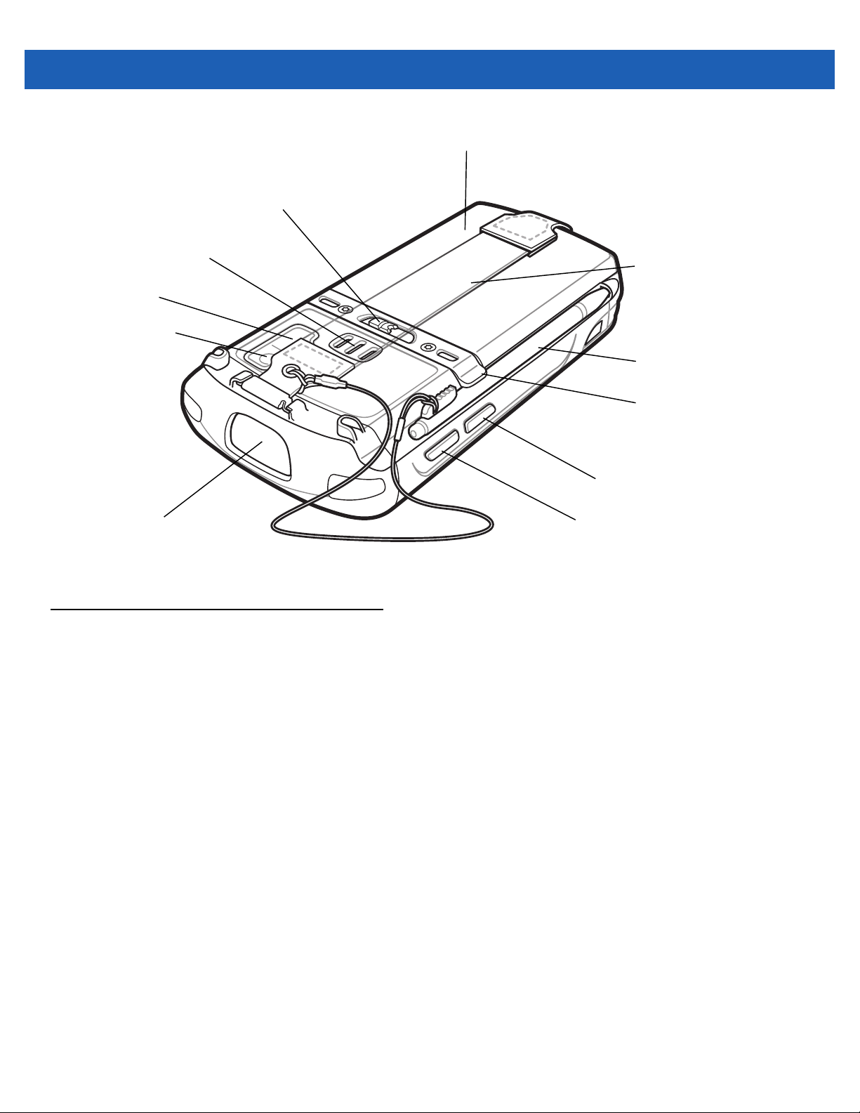
Battery
Battery Latch
Speaker
Camera Flash
Camera
Handstrap
Stylus
Stylus Clip
Exit Window
Figure 1-2
Unpacking
Carefully remove all protective material from the MC55 and save the shipping container for later storage and
shipping.
Verify that you received the following:
•
MC55 EDA
•
2400 or 3600 mAh Lithium-ion battery
•
stylus with tether (installed)
•
screen protector, installed on display window
•
Regulatory Guide
•
Quick Start Guide.
Action Button
Scan/Action Button
MC55 Rear View
Inspect the equipment for damage. If any equipment is missing or damaged, contact the Motorola Enterprise
Mobility Support center immediately. See page xv for contact information.
Prior to using the MC55 for the first time, remove the protective shipping film that covers the scan window,
display and camera window.
Page 21
Getting Started
To start using the MC55 for the first time:
•
Install a microSD card (optional)
•
Install the main battery.
•
Charge the MC55.
•
Power on the MC55.
Installing a microSD Card (MC55A0)
The microSD card slot provides secondary non-volatile storage. The slot is located under the battery. Refer to
the documentation provided with the card for more information, and follow the manufacturer’s
recommendations for use.
CAUTION Follow proper ESD precautions to avoid damaging the SD card. Proper ESD precautions include, but
are not limited to, working on an ESD mat and ensuring that the operator is properly grounded.
Getting Started 1 - 3
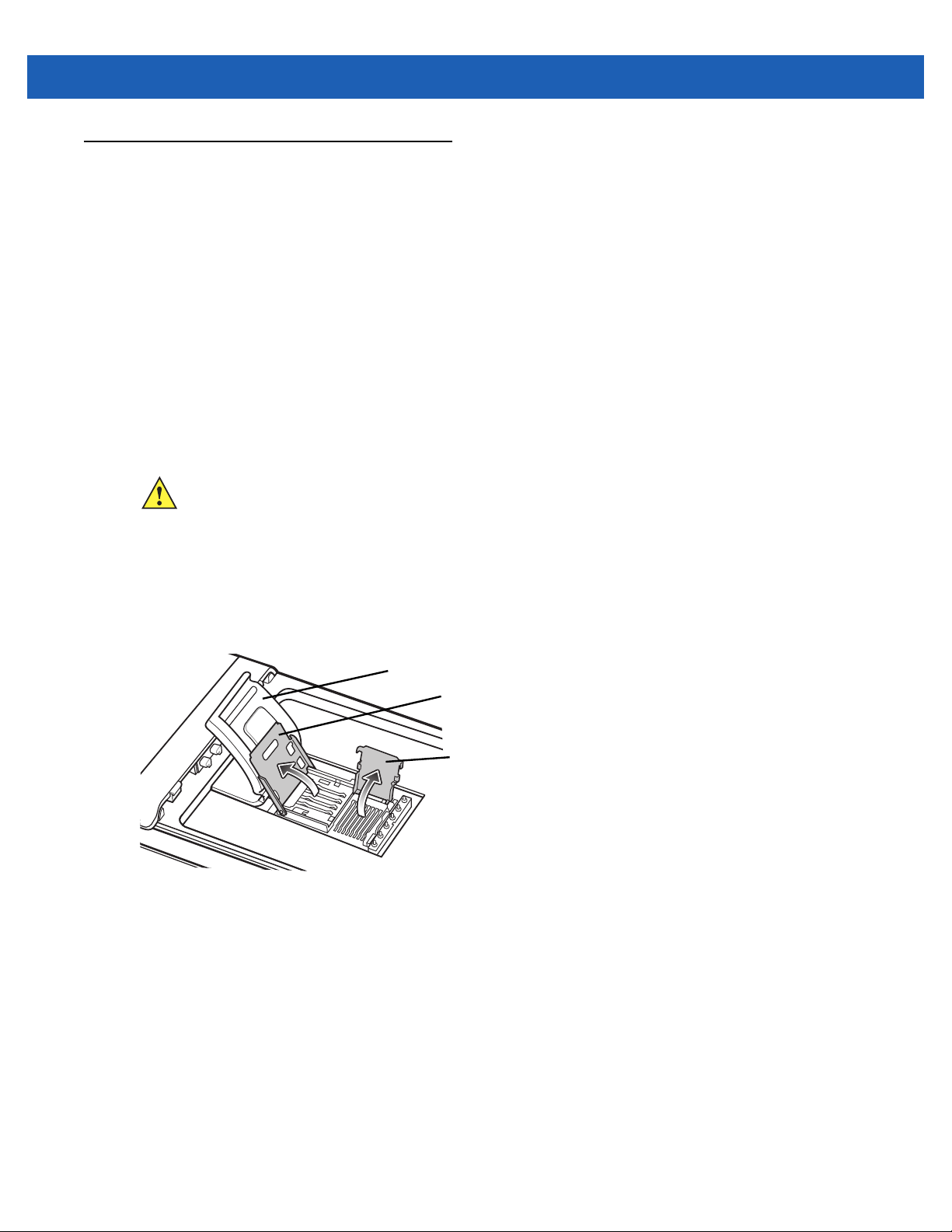
To install the microSD card:
1. Lift rubber access door.
2. Slide the SIM card holder door up to unlock.
3. Lift SIM card holder door.
Rubber access door
SIM card holder door
microSD card holder door
Figure 1-3
4. Lift microSD card holder door.
5. Insert the microSD card into card holder door ensuring that the card slides into the holding tabs on each
side of the door.
Lift SIM Slot Holder Door
Page 22
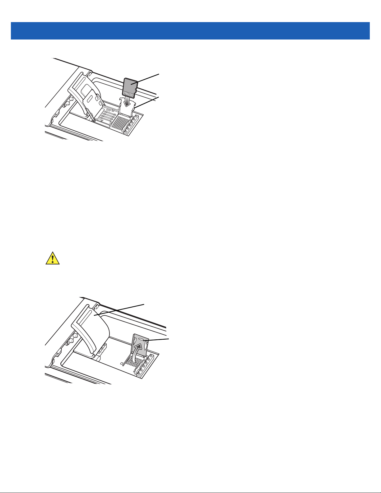
1 - 4 MC55A0/MC55N0 Enterprise Digital Assistant User Guide
microSD card
Holding tab
Figure 1-4
6. Close the card holder door and push down until it is securely into place.
7. Close SIM card holder door and slide down until it locks into place.
8. Close rubber access door.
Insert microSD Card in Holder
Installing a microSD Card (MC55N0)
The microSD card slot provides secondary non-volatile storage. The slot is located under the battery. Refer to
the documentation provided with the card for more information, and follow the manufacturer’s
recommendations for use.
CAUTION Follow proper ESD precautions to avoid damaging the SD card. Proper ESD precautions include, but
are not limited to, working on an ESD mat and ensuring that the operator is properly grounded.
To install the microSD card:
1. Lift rubber access door.
Rubber access door
microSD card holder door
Figure 1-5
2. Slide the microSD card holder door to the right to unlock.
3. Lift microSD card holder door.
4. Insert the microSD card into card holder door ensuring that the card slides into the holding tabs on each
Lift SIM Slot Holder Door
side of the door.
Page 23
microSD card
Holding tab
Getting Started 1 - 5
Figure 1-6
5. Close the card holder door.
6. Slide to the left to lock into place.
7. Close rubber access door.
Insert microSD Card in Holder
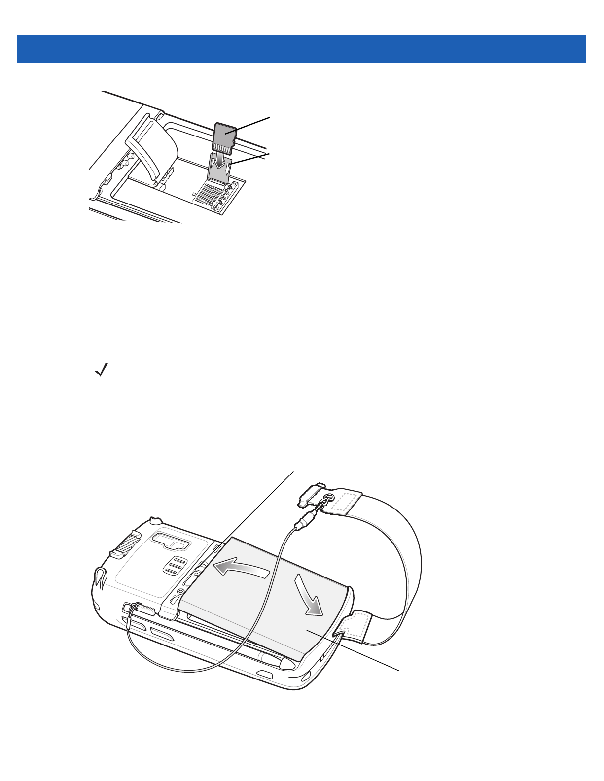
Installing the Battery
NOTE The MC55 ships with either a 2400 mAh or 3600 mAh battery. The 2400 mAh battery is shown in this
installation procedure.
To install the battery.
1. Insert the battery, bottom first, into the battery compartment in the back of the MC55.
2. Press the battery down into the battery compartment until the battery release latch snaps into place.
Battery Release Latch
2
1
Battery
Figure 1-7
Inserting the Battery
The MC55 powers up automatically after inserting the battery if the battery has been charged previously.
Page 24

1 - 6 MC55A0/MC55N0 Enterprise Digital Assistant User Guide
Charging the Battery
CAUTION Ensure that you follow the guidelines for battery safety described in Battery Safety Guidelines on page
6-2.
Charging the Main Battery
Before using the MC55 for the first time, charge the main battery until the amber Charging/Battery Status LED
remains lit (see Table 1-1 on page 1-6 for charge status indications). To charge the MC55, use a cable or a
cradle with the appropriate power supply. For information about the accessories available for the MC55, see
Chapter 5, Accessories.
The MC55 is equipped with a memory backup battery which automatically charges from the fully-charged main
battery. When using the MC55 for the first time, the backup battery requires approximately 40 hours to fully
charge. This is also true any time the backup battery is discharged, which occurs when the main battery is
removed for several hours. The backup battery retains RAM data in memory for at least 15 minutes (at room
temperature) when the MC55’s main battery is removed. When the MC55 reaches a very low battery state, the
combination of main battery and backup battery retains RAM data in memory for at least 48 hours.
For cable and cradle setup and charging procedures refer to the MC55 Integrator Guide.
•
USB Charging Cable
•
Charge Only Cable
•
Single-slot USB Cradle
•
Single-slot Ethernet/Modem/USB Cradle
•
Four-slot Charge Only Cradle.
To charge the main battery:
1. Connect the charging accessory to the appropriate power source.
2. Insert the MC55 into a cradle or attach to a cable. The MC55 begins charging. The Charging/Battery Status
LED blinks amber while charging, then turns solid amber when fully charged. See Table 1-1 for charging
indications.
The 2400 mAh battery fully charges in less than four hours and the 3600 mAh battery charges in less than six
hours.
Table 1-1
Off MC55 is not charging.
Slow Blinking Amber
(1 blink every 2 seconds)
LED Charge Indicators
Charging/Battery
Status LED
Indication
MC55 is not inserted correctly in the cradle or connected to a power source.
Charger/cradle is not powered.
MC55 is charging.
Solid Amber Charging complete.
Note: When the battery is initially inserted in the MC55, the amber LED flashes
once if the battery power is low or the battery is not fully inserted.
Page 25

Getting Started 1 - 7
Table 1-1
Fast Blinking Amber
(2 blinks/second)
Single Blink Amber (when
Power button pressed)
Blinking Amber (when
Power button pressed)
LED Charge Indicators (Continued)
Charging/Battery
Status LED
Charging error, e.g.:
•
•
Battery depleted.
Battery over-temperature condition.
Indication
Temperature is too low or too high.
Charging has gone on too long without completion (typically eight hours).
Charging Spare Batteries
See Chapter 5, Accessories for information on using accessories to change spare batteries.
Charging Temperature
Charge batteries in temperatures from 0°C to 40°C (32°F to 104°F). Note that charging is intelligently
controlled by the MC55.
To accomplish this, for small periods of time, the MC55 or accessory alternately enables and disables battery
charging to keep the battery at acceptable temperatures. The MC55 or accessory indicates when charging is
disabled due to abnormal temperatures via its LED. See Table 1-1.
Powering On the MC55
After inserting the battery or when turning the MC55 on for the first time, the splash screen displays for about a
minute as the MC55 initializes its flash file system, then the calibration window appears. Note that these
windows also appear upon cold boot.
Calibrating the Screen
NOTE The Calibration screen can be accessed by pressing Blue key then Backspace key.
To calibrate the screen so the cursor on the touch screen aligns with the tip of the stylus:
1. Remove the stylus from its holder on the side of the MC55.
2. Carefully press and briefly hold the tip of stylus on the center of each target that appears on the screen.
3. Repeat as the target moves around the screen, then tap the screen to continue.
Checking Battery Status
NOTE To check battery status, remove the MC55 from any AC power source (cradle, cables, etc.)
To check the charge status of the main battery in the MC55, tap > Settings > System > Power to display
the Power window.
To save battery power, tap the Advanced tab and set the MC55 to turn off after a specified number of minutes.
Page 26
1 - 8 MC55A0/MC55N0 Enterprise Digital Assistant User Guide
1
Replacing the Battery
1. Press the red Power button to suspend the MC55. The PowerKey Action window appears.
2. Tap Safe Battery Swap. The Decode LED lights red and then turns off.
3. Unlatch the handstrap.
4. Use finger or stylus to slide the battery latch to the right releasing the battery. The battery ejects slightly.
Battery Latch
2
Figure 1-8
5. Lift the battery from the MC55.
6. Insert the replacement battery, bottom first, into the battery compartment in the back of the MC55.
7. Press the battery down until the battery release latch snaps into place.
8. Re-attach the handstrap.
Removing the Battery
Removing the microSD Card (MC55A0)
To remove an microSD card:
1. Press the red Power button to suspend the MC55. The PowerKey Action window appears.
2. Tap Safe Battery Swap. The Decode LED lights red and then turns off.
3. Unlatch the handstrap.
4. Remove the battery.
5. Lift the rubber access door.
6. Slide SIM card holder door up to unlock.
7. Lift SIM Card holder door.
8. Lift the microSD card holder door.
9. Remove microSD card from holder.
10. Close microSD card holder door.
Page 27

11. Close SIM card holder door.
12. Slide SIM card holder door down to lock into place.
13. Close the rubber access door.
14. Replace the battery.
15. Re-attach the handstrap.
Removing the microSD Card (MC55N0)
To remove an microSD card:
1. Press the red Power button to suspend the MC55. The PowerKey Action window appears.
2. Tap Safe Battery Swap. The Decode LED lights red and then turns off.
3. Unlatch the handstrap.
4. Remove the battery.
Getting Started 1 - 9
5. Lift the rubber access door.
6. Slide the microSD card holder door to the right to unlock.
7. Lift the microSD card holder door.
8. Remove microSD card from holder.
9. Close microSD card holder door.
10. Slide the microSD card holder door to the left to lock.
11. Close the rubber access door.
12. Replace the battery.
13. Re-attach the handstrap.
Battery Management
Observe the following battery saving tips:
•
Leave the MC55 connected to AC power at all times when not in use.
•
Set the MC55 to turn off after a short period of non-use.
•
Set the backlight to turn off after a short period of non-use.
•
Turn off all wireless activities when not in use.
Changing the Power Settings
To set the MC55 to turn off after a short period of non-use:
1. Tap > Settings > System > Power > Advanced tab.
Page 28
1 - 10 MC55A0/MC55N0 Enterprise Digital Assistant User Guide
2. Select the On battery power: Turn off device if not used for check box and select a value from the
drop-down list.
3. Select OK.
Changing the Backlight Settings
To change the backlight settings in order to conserve more battery power:
1. Tap > Settings > System > Backlight > Battery Power.
2. Select the Disable backlight if device is not used for check box and select a value from the drop-down
list.
3. Select Brightness.
4. Tap the Disable backlight check box to turn off the display backlight, or use the slider to set a low value
for the backlight.
5. Select OK.
Changing the Keypad Backlight Settings
To change the keypad backlight settings in order to conserve more battery power:
1. Tap > Settings > System > Keylight > Battery Power.
2. Select the On battery power: Disable keylight if device if not used for check box and select a value
from the drop-down list.
3. Select Advanced.
4. Tap the Disable keylight check box to turn off the keypad backlight.
5. Select OK.
Turning Off the Radios
To open Wireless Manager, tap status bar and then select the Connectivity icon.
Connectivity icon
Figure 1-9
Opening Wireless Manager
Page 29
Select Wireless Manager.
Getting Started 1 - 11
Figure 1-10
To enable or disable a wireless connection, tap the specific button.
To enable or disable all wireless connections, tap and hold the All button.
To configure settings for a connection, tap Menu.
Wireless Manager Window
Page 30
1 - 12 MC55A0/MC55N0 Enterprise Digital Assistant User Guide
Handstrap Replacement
Removal
To remove the handstrap:
1. Press the red Power button to suspend the MC55. The PowerKey Action window appears.
2. Tap Safe Battery Swap. The Decode LED lights red and then turns off.
3. Slide the handstrap clip out of the handstrap slot.
Figure 1-11
4. Remove the stylus tether from the handstrap.
5. Remove the battery.
6. Using a small flat screwdriver, push the head of the screwdriver between the handstrap pin and the bottom
of the housing as shown below.
7. Pry the handstrap and pin up and out of the handstrap mounting area.
Handstrap Clip Removal
CAUTION When removing handstrap pin, be carefully not to damage handstrap mounting area.
Page 31

Getting Started 1 - 13
12
34
Figure 1-12
8. Repeat for the other side of the handstrap.
9. Remove the pin from the handstrap.
Figure 1-13
10. Pull the handstrap through the handstrap slot.
Handstrap and Pin Removal
Pin Removal
Installation
To install the handstrap:
1. Feed the bottom end of the handstrap into the handstrap slot on the bottom of the MC55.
Page 32

1 - 14 MC55A0/MC55N0 Enterprise Digital Assistant User Guide
Figure 1-14
2. Slide the pin into the bottom of the handstrap.
3. Center the pin in the handstrap loop.
4. Pull the handstrap so that the pin and bottom of the handstrap slide into position in the mounting area.
Figure 1-15
5. Replace the battery.
Feed Handstrap into Handstrap Slot
NOTE Handstrap and pin should fit securely into the handstrap mounting area. When pulling on handstrap use
enough force to engage pin into place.
Pin and Handstrap in Mounting Area
6. Replace the stylus tether onto the handstrap.
Figure 1-16
7. Insert the handstrap clip into the slot on the MC55. Ensure that it is securely in place.
Slide Handstrap and Tether Over Handstrap Mount
Page 33

CHAPTER 2 OPERATION
Introduction
This chapter explains the buttons, status icons, and controls on the MC55, and provides basic instructions for
using the MC55, including powering on and resetting.
Finger Scrolling
Finger scrolling can be used to scroll up and down web pages, documents, and lists such as the contacts list,
file list, message list, calendar appointments list, and more.
When finger scrolling, swipe or flick your finger on the screen.
To scroll down, swipe your finger upward on the screen. To scroll up, swipe your finger downward on the
screen.
To auto-scroll, flick your finger upward or downward on the screen. Touch the screen to stop scrolling.
Home Screen
The default home screen on the MC55 is the Windows Mobile Home screen. The Home screen contains a
Status Bar at the top of the screen and a Tile Bar at the bottom of the screen.
The Home screen is scrollable and contains a list of application plug-ins and an Information Status bar. The
Information Status bar highlights the application plug-in that is under it and provides additional information.
Page 34

2 - 2 MC55A0/MC55N0 Enterprise Digital Assistant User Guide
Status Bar
Home Screen
Tile Bar
Open the Start Menu
Figure 2-1
Windows Mobile Home Screen
Tiles
Touch and hold the screen with your finger and move the Home screen up and down. As the application names
move under the Information Status bar, information relevant to that application appear in the bar.
Figure 2-2
Moving Today Screen
You can also touch and hold the Information Status bar and move it up and down over an application name.
Remove your finger and the Information Status bar and application name center in the screen.
Figure 2-3
Moving Information Status Bar
Page 35

Application Icon
Application Information
Operation 2 - 3
Figure 2-4
To customize the
Information Bar Example
Home screen, tap > Settings > Today. On the horizontal scroll, use Appearance to
customize the background and the Items to change the display format.
Classic Today Screen
The user can change to the classic Today screen layout that is used in Windows Mobile 6.1.
Status Bar
Today Screen
Task Tray
Tile Bar
Figure 2-5
Classic Today Screen
To change to the classic view tap > Settings > Home > Items.
Page 36

2 - 4 MC55A0/MC55N0 Enterprise Digital Assistant User Guide
Figure 2-6
Deselect the Windows Default checkbox and select any of the other checkboxes.
Tap .
The task bar at the bottom of the screen can contain the task tray icons listed in Table 2-1.
Table 2-1
Icon Name Description
Home Screen Settings
Task Tray Icons
Wireless connection
status
Bluetooth Enabled The
Bluetooth Disabled The
Bluetooth
Communication
Wireless connection status icon. Indicates WLAN signal strength and opens
the Wireless Applications menu.
Bluetooth radio is on (Displays only if the StoneStreet One Bluetooth stack
is enabled).
Bluetooth radio is off (Displays only if the StoneStreet One Bluetooth stack
is enabled).
The
that the mobile computer is communicating with another Bluetooth device
(Displays only if the StoneStreet One Bluetooth stack is enabled).
Bluetooth Enabled
Bluetooth Disabled
Bluetooth Communication
icon appears in the task tray and indicates that the
icon appears in the task tray and indicates that the
icon appears in the task tray and indicates
Status Bar
The Status Bar at the top of the screen displays the status icons listed in Table 2-2.
Page 37

Notifications
Connectivity
Audio
Battery
Battery
Clock
Operation 2 - 5
Figure 2-7
Table 2-2
Status Bar Icons
Status Bar Icons
Icon Description Icon Description
Notifications
Indicates a reminder of an upcoming
calendar event.
Notification that one or more e-mail/text
messages were received.
Notification that one or more instant
messages were received.
There are more notification icons than can
be displayed.
Indicates that the backup battery is very low. Indicates that a wireless stereo headset is
connected to the MC55.
Connectivity
Connection is active. Connection is not active.
Synchronization is occurring. Wi-Fi available.
Wi-Fi in use.
Audio
All sounds are on. All sounds are off.
Vibrate is on.
Battery
Battery is charging. Battery has a full charge.
Battery has a high charge. Battery has a medium charge.
Battery has a low charge. Battery has a very low charge.
Tap the Status Bar to display an icon bar. Tap an icon to get additional notification or status information.
Page 38

2 - 6 MC55A0/MC55N0 Enterprise Digital Assistant User Guide
Icon Bar
Figure 2-8
Table 2-3
Icon Name Description
Icon Bar
Task Tray Icons
Magnify Enlarges the screen.
Notifications Indicates that notifications are available.
Headset Indicates that a wireless stereo headset is connected to the MC55.
Connectivity Displays the Connectivity dialog box.
Volume Displays the Volume dialog box.
Power Displays the Power window.
Clock & Alarms Opens the Clocks & Alarms window.
Tile Bar
The Tile Bar, located at the bottom of the screen, contains the Start tile to open the Start Menu. It also
displays tiles that vary depending upon the open application.
Figure 2-9
Tile Bar Examples
Start Screen
To open the Start screen, tap at the bottom left corner of the screen, or press the START key on the
keypad.
Page 39

Operation 2 - 7
Swipe upward to view more program and folder icons.
Move often-used program and folder icons anywhere on the Start screen for easy access. Press and hold the
icon and drag the icon to a new location and release.
Table 2-4 lists the default icons available on the Start screen.
Table 2-4
Icon Name Description Icon Name Description
Programs on the Start Screen
Home Displays the Home screen. Text Send an SMS text message.
Battery Swap Properly shuts down the
MC55 during battery
replacement.
Contacts Keep track of friends and
colleagues.
Internet
Explorer
Calendar Keep track of appointments
Browse Web and WAP sites
as well as download new
programs and files from the
Internet.
and create meeting
requests.
E-mail Send an Email.
Settings Open the Settings folder.
Table 2-5
icons available on the
Settings folder.
Getting
Started
Alarms Set the device clock to the
Launch the Getting Started
application.
date and time of your locale.
Alarms can also be set at
specified days and times of
a week.
lists the default
Pictures &
Videos
Windows
Media
Marketplace Purchase applications from
Windows
Live
MSN Money Keep track of your finances. Notes Create handwritten or typed
View and manage pictures,
animated GIFs, and video
files.
Play back audio and video
files.
the Marketplace.
Use this mobile version of
Windows Live™ to find
information on the web.
Messenger Use this mobile version of
Windows Live Messenger.
Microsoft My
Phone
MSN
Weather
Games Play games.
Synchronizes the MC55’s
contacts, calendar, tasks,
text messages, music,
photos videos and
documents with a Microsoft
My Phone account.
Check the local weather.
notes, drawings, and voice
recordings.
Page 40

2 - 8 MC55A0/MC55N0 Enterprise Digital Assistant User Guide
Table 2-4
Icon Name Description Icon Name Description
Programs on the Start Screen (Continued)
Calculator Perform basic arithmetic
and calculations, such as
addition, subtraction,
multiplication, and division.
Office Mobile Use the complete suite of
Microsoft® Office
applications for your mobile
device.
File Explorer Organize and manage files
on your device.
ActiveSync Synchronize information
between the MC55 and a
host computer or the
Exchange Server.
Tasks Keep track of your tasks.
Internet
Sharing
Task
Manager
Search
Phone
Connect a notebook
computer to the Internet
using the MC55's data
connection.
Enables viewing of memory
and CPU allocations and
stops running processes.
Refer to the Microsoft
Applications for Windows
Mobile 6 User Guide for
more information.
Search contacts, data, and
other information on the
MC55. Refer to the
Microsoft Applications for
Windows Mobile 6 User
Guide for more information.
Help Access on-line Help topics. BT
Information
Wireless
Companion
AirBEAM
Client
Open the Wireless
Companion folder.
Allows legacy customers to
deploy AirBEAM Smart™
packages to devices.
BTScanner
CtlPanel
Adobe
Reader
Display information about
the Bluetooth radio and
generate a Bluetooth
address bar code.
Set com port to use with a
Bluetooth scanner.
View pdf files.
Page 41

Operation 2 - 9
Table 2-4
Icon Name Description Icon Name Description
Programs on the Start Screen (Continued)
Modem Link Enables the MC55 to be
used as a modem.
MSP Agent Enables management of the
MC55 from an MSP Server.
Requires the purchase of an
appropriate MSP client
license per device to suit the
level of management
functionality required.
DEMO Provides a link to Motorola’s
featured demos.
Remote
Desktop
Mobile
Rapid
Deployment
Client
BTExplorer Manages StoneStreet One
Log onto Windows NT
server type computers and
use all of the programs that
are available on that
computer from the MC55.
Allows the MC55 user to
stage a device for initial use
by initiating the deployment
of settings, firmware, and
software. Requires the
purchase of an MSP client
license per device.
Bluetooth connections.
Refer to the MC55 Series
Mobile Computer Integrator
Guide for more information.
Appears only if the
StoneStreet One Bluetooth
stack is enabled.
Table 2-5
Icon Name Description Icon Name Description
Setting Applications
Clock &
Alarms
Home Customize the appearance
Personal
Folder
System Folder Contains system setting
Set the device clock to the
date and time of your
locale. Alarms can also be
set at specified days and
times of a week.
of the Home screen and the
information to display on it.
Contains personal setting
applications.
applications.
Lock Set a password for the
MC55.
Sounds &
Notifications
Connections
Folder
Microsoft My
Phone
Enable sounds for events,
notifications, and more, and
set the type of notification
for different events.
Contains connection setting
applications.
Synchronizes the phone’s
contacts, calendar, tasks,
text messages, music,
photos, videos and other
documents with your My
Phone account at
www.microsoft.com.
Page 42

2 - 10 MC55A0/MC55N0 Enterprise Digital Assistant User Guide
Table 2-5
Icon Name Description Icon Name Description
Connections Folder
Setting Applications (Continued)
Beam Set the MC55 to receive
incoming IrDA beams. Not
supported on MC55.
Bluetooth Open the Bluetooth
application, set the MC55
to visible mode and scan
for other Bluetooth devices
in the area.
Wi-Fi Setup wireless network
connection and customize
settings.
Connections Set up one or more types of
modem connections for your
device, such as phone
dial-up, GPRS, Bluetooth,
and more, so that your
device can connect to the
Internet or a private local
network.
Domain
Enroll
USB to PC Enables or disables the
Make your device an AD
domain member for device
management and security.
Refer to the Microsoft
Applications for Windows
Mobile 6 User Guide for
more information.
enhanced network
connectivity.
Wireless
Manager
Personal Folder
Buttons Assign a program to a
System Folder
About View basic information
Backlight Set backlight settings. Customer
Error
Reporting
Enables or disables the
MC55’s wireless radios and
customizes Wi-Fi, and
Bluetooth settings.
button.
such as the Windows
Mobile® version and type of
processor used on the
MC55.
Enable or disable the
Microsoft’s error reporting
function.
Owner
Information
Certificates See information about
Feedback
Encryption Allow files on a storage card
Enter personal information
on the MC55.
certificates installed on the
MC55.
Submit feedback on the
Windows Mobile 6 software.
to be encrypted. Encrypted
files are readable only on
your device.
Managed
Programs
Displays the programs that
were installed on the MC55
using Mobile Device
Manager.
Keylight Set the keypad backlight
time-out.
Page 43

Operation 2 - 11
Table 2-5
Icon Name Description Icon Name Description
Setting Applications (Continued)
Memory Check the device memory
allocation status and
memory card information
and stop currently running
programs.
Power Check battery power and
set the time-out for turning
off the display to conserve
battery power.
Screen Change the screen
orientation, re-calibrate the
screen, and change the
screen text size.
Task Manager Stop running programs. USBConfig Configure the MC55 USB
UI Settings Set Start Screen layout and
IE zoom feature.
Regional
Settings
Remove
Programs
System Info Displays the MC55’s
DataWedge Sample scanning
Set the regional
configuration to use,
including the format for
displaying numbers,
currency, date, and time on
the MC55.
Remove programs that you
installed on the MC55.
software and hardware
information.
port.
application.
IST Settings Configure the MC55
UI Settings
Use the UI Settings application to change the grid view in the Start screen and to control Zooming in Internet
Explorer.
Start Screen Settings
To change the grid view of the Start screen:
1. Tap > Settings > System > UI Settings.
2. Tap the Start Screen Settings tab.
accelerometer.
Page 44

2 - 12 MC55A0/MC55N0 Enterprise Digital Assistant User Guide
Figure 2-10
3. Select the number of columns.
4. Tap OK.
5. Tap OK.
6. Preform a warm boot.
Start Screen Settings Tab
NOTE Tap Reset to return to the default 3 Column setting.
IE Zoom Mapping
When Internet Explorer opens, the volume keys on the side of the MC55 are used to zoom in and out. To
disable IE zoom mapping:
1. Tap > Settings > > System > UI Settings.
2. Tap the IE Zoom Mapping tab.
Figure 2-11
3. Select Off.
4. Tap OK.
5. Tap OK to turn off mapping.
IE Zoom Mapping Tab
Page 45

Locking the MC55
Lock the MC55 by disabling key presses and screen tap or by requiring a password.
Locking the MC55 turns off keyboard and touch screen functionality. This is helpful when the MC55 is turned
on and you want to prevent accidental key presses.
To lock the device, tap > .
Locking without PIN or Password
When the MC55 is locked, the Lock screen appears.
Operation 2 - 13
Figure 2-12
Tap Unlock and then tap Unlock again.
Lock Screen
Locking with Simple PIN
When the MC55 is locked, the Lock screen appears.
Figure 2-13
Enter the PIN and then tap Unlock.
Simple PIN Lock Screen
Page 46

2 - 14 MC55A0/MC55N0 Enterprise Digital Assistant User Guide
Locking with Strong Password
When the MC55 is locked, the Lock screen appears.
Figure 2-14
Strong Password Lock Screen
Enter the strong password and then tap Unlock.
Password Locking Setup
Use the Password window to set a password to disable unauthorized access to the MC55.
NOTE If the device is configured to connect to a network, use a strong (difficult to figure out) password to help
protect network security. Password cracking tools continue to improve and the computers used to crack
passwords are more powerful than ever.
1. Tap > Settings > Lock > Password.
Figure 2-15
2. Select Prompt if device unused for check box to enable password protection.
3. From the drop-down list, select a time value for the protection to take affect after non-use.
4. From the Password type: drop-down list, select either Simple PIN or Strong alphanumeric.
5. For a simple password, enter a four-digit password in the Password field.
Password Window
For a stronger password:
Page 47

a. Enter a seven character password in the Password: field. A strong password must contain at least
seven characters and contain at least three of the following: uppercase and lowercase letters,
numerals, and punctuation.
b. Re-enter the password in the Confirm: field.
6. Tap OK.
7. Tap OK.
Battery Status Indications
Battery icons appear on the navigation bar indicating the battery power level. When the main battery power
falls below a predetermined level the icon indicates the status and a battery dialog box appears indicating the
status of the battery.
Operation 2 - 15
Figure 2-16
The Battery icon always appears in the Status bar. The icon indicates the battery power level. The message
displays until the Dismiss button is pressed.
Also view the battery status using the Power window. Either:
•
•
Figure 2-17
Battery Status Dialog Box
Tap the Status bar and then the Battery icon.
Tap > Settings > System > Power.
Settings Power Window
Page 48

2 - 16 MC55A0/MC55N0 Enterprise Digital Assistant User Guide
Battery Reserve Options
If the charge of the battery reaches a critical threshold, the MC55 shuts down. This threshold can be changed
but affects the amount of time that data can be retained.
1. Tap > Settings > System > Power > RunTime. A warning message appears.
Figure 2-18
2. Read the warning message and tap OK.
Figure 2-19
3. Select one of the Battery Reserve Options.
•
•
Warning Message
RunTime Tab
Option 1: Minimum - After a low battery shutdown, data will be retained for minimum amount of time.
Battery should be replaced immediately to avoid data loss.
Option 2: Less - After a low battery shutdown, data will be retained for less than normal amount of time.
•
Option 3: Normal - After a low battery shutdown, data will be retained for maximum amount of time.
4. Tap OK.
Main Battery Temperature Notifications
The temperature notification system implements three levels of notification when the temperature within the
battery exceeds specific temperature thresholds:
Page 49

Operation 2 - 17
•
Level 1: Temperature Watch; this level is similar to main battery low warning. It indicates that the
battery temperature has reached the first threshold level. The user should move to an environment within
proper operating temperature.
•
Level 2: Temperature Warning; this level is similar to main battery very low warning. It indicates the
battery temperature has reached the second threshold level. The user should close all running
applications and stop using the MC55.
•
Level 3: Temperature Error; this level indicates the battery has reached an unusable temperature
threshold and immediately suspends the MC55. This level does not have any graphical notification
associated with it.
Figure 2-20
Figure 2-21
Main Battery Temperature Watch Dialog Box
Main Battery Temperature Warning Dialog Box
NOTE The Temperature Warning dialog box remains visible until you tap Hide.
Battery Health
The health of the battery can be viewed on the MC55 Power applet. Tap > Settings > System > Power >
BatteryMgmt.
Page 50

2 - 18 MC55A0/MC55N0 Enterprise Digital Assistant User Guide
Figure 2-22
Table 2-6
State of Health Indicates the current state of the battery (Healthy or Unhealthy).
Battery Usage Indicator Indicates the usage of the battery.
Battery Usage Threshold Indicates the usage indicator threshold.
Battery Serial # Displays the serial number of the battery.
For information on changing the Battery Usage Threshold, refer to the MC55 Integrator Guide.
Battery Management Dialog Box
Battery Information
Item Description
Page 51

LED Indicators
The MC55 has three LED indicators. The Scan/Decode LED indicates status for scanning. The
Charging/Battery Status LED indicates battery charging and status.
Scan/Decode
LED
Charging/Battery
Charging/Battery
Status LED
Status LED
Operation 2 - 19
Figure 2-23
Table 2-7
Scan/Decode LED
Solid Green Successful decode/capture.
Solid Red Laser enabled, scanning/imaging in process.
Off Not enabled.
Charging/Battery Status LED
Slow Blinking Amber Main battery in MC55 is charging.
Solid Amber Main battery in MC55 is fully charged.
Fast Blinking Amber Charging error.
Off Not charging.
Single Blink Amber (when Power button pressed) Battery depleted.
Blinking Amber (when Power button pressed) Battery over-temperature condition.
LED Indicators
LED Indications
LED State Indication
NOTE For information about scanning/decoding, see Chapter 3, Data Capture.
Resetting the MC55
There are two reset functions, warm boot and cold boot. A warm boot restarts the MC55 by closing all running
programs. A cold boot also restarts the MC55, and also initializes some drivers. Data saved in flash memory or
a memory card is not lost.
If the MC55 is not functioning properly, perform a warm boot first. If the MC55 still does not respond, perform a
cold boot.
Page 52

2 - 20 MC55A0/MC55N0 Enterprise Digital Assistant User Guide
Performing a Warm Boot
Hold down the red Power button for approximately five seconds. As soon as the MC55 starts to boot (splash
screen displays) release the Power button.
Performing a Cold Boot
To perform a cold boot:
•
On a numeric keypad, simultaneously press the red Power button and the and keys.
•
On an alphanumeric keypad, simultaneously press the red Power button and the and keys.
•
On an PIM keypad, simultaneously press the red Power button and the and keys.
Waking the MC55
The wake-up conditions define what actions wake up the mobile computer after it has gone into suspend
mode. The mobile computer can go into suspend mode by either pressing the Power button or automatically by
Control Panel time-out settings. These settings are configurable and the factory default settings are shown in
Table 2-8 are subject to change/update.
Table 2-8
AC power is applied. No Yes
Mobile computer is inserted into a cradle. No Yes
Mobile computer is removed from a cradle. No Yes
Mobile computer is connected to a USB device. Yes Yes
A key is pressed. No Yes
The scan triggered is pressed. No Yes
The screen is touched. No No
Bluetooth communication Yes Yes
IST activity No Yes
USB Host connected No No
Wake-up Default Settings
Condition for Wake-up Power Button Automatic Time-out
Page 53

Function Buttons
The MC55’s buttons perform certain functions.
Scan/Action
Button
Volume
Up/Down
Button
Operation 2 - 21
Action Button
Stylus
Scan/Action
Power Button
Figure 2-24
•
•
•
•
Use the MC55 stylus to select items and enter information. The stylus functions as a mouse.
•
Function Buttons
Power: Press the red Power button to turn the MC55 screen on and off. The MC55 is in suspend mode
when the screen is off. For more information, see Powering On the MC55 on page 1-7. Also use the
Power button to reset the MC55 by performing a warm or cold boot. See Resetting the MC55 on page
2-19.
Scan/Action: Press to scan bar codes or capture images. See Chapter 3, Data Capture.
Or, press to open an application or perform a function. See the Microsoft® Applications for Mobile 6 User
Guide to set an application to open.
Volume Up/Down: Press to increase or decrease the MC55’s volume.
Action: Press to open an application or perform a function. See the Microsoft® Applications for Windows
Mobile 6 User Guide to set an application to open.
Tap: Touch the screen once with the stylus to press option buttons and open menu items.
Button
•
Tap and Hold: Tap and hold the stylus on an item to see a list of actions available for that item. On the
pop-up menu that appears, tap the action to perform.
•
Drag: Hold the stylus on the screen and drag across the screen to select text and images. Drag in a list to
select multiple items.
CAUTION To prevent damage to the screen, do not use any device other than the Motorola-provided stylus.
Page 54

2 - 22 MC55A0/MC55N0 Enterprise Digital Assistant User Guide
Entering Data
When entering data on the keypad, use either the single-hand method or the two-hand method as shown in
Figure 2-25.
Single-hand Method
Figure 2-25
Entering Data on the Keypad
Using Voice-Over-IP
NOTE Voice-Over-IP is currently supported on the MC55A0. It will be supported on the MC55N0 in a
future update.
The MC55 supports Voice over IP over WLAN (VoWLAN) using Motorola or third party voice clients. The MC55
can communicate using VoIP either using the MC55 supports several audio outputs, including back speaker
phone, front receiver or handset, and Bluetooth headset.
It is recommended that the wireless network use the 802.11a (5 GHz) band for voice applications. Using the 5
GHz band avoids some noise sources that may occur on the 802.11b/g (2.4 GHz) band due to wireless
interference.
When using a Bluetooth headset with the MC55 and VoWLAN, it is required to use the Bluetooth Headset
profile instead of Hands-free profile. Use the buttons on the MC55 to answer and end calls. See Chapter 4,
Bluetooth for information on setting up a Bluetooth Headset Profile.
Two-hand Method
Page 55

Interactive Sensor Technology
The Interactive Sensor Technology (IST) supports the following features:
•
Power Management – manages power by configuring IST to control switching on/off the backlight,
control suspend mode of the MC55 by monitoring motion and orientation.
•
Display Orientation – switches the screen orientation to either landscape or portrait depending on the
MC55 orientation.
•
Free Fall Detection – monitors free fall duration and records the time and type of the drop event.
Power Management
The MC55 orientation and motion sensitive data can be used as an indicator of MC55 usage and can be used
to manage the battery power of the mobile computer. For example, IST can be configured to control the
backlight on and off functionality or go into suspend according to a user gesture by placing screen facing down.
It can also be used to keep the MC55 active while it is in movement to prevent it from quickly going into
suspend mode while in use.
Operation 2 - 23
Display Orientation
The screen can be rotated between portrait and landscape modes automatically, depending on the physical
orientation of the MC55. For example, if the MC55 is rotated 90° counterclockwise, IST rotates the display
counterclockwise 90° so that the screen display appears correct.
This functionality is achieved by monitoring screen angle and rotating the display to counter any changes. IST
only rotates the screen in multiples of 90°.
Free Fall Detection
IST continuously monitors gravitational force on the MC55 according to its current position. When the MC55
free falls, IST detects the absence of gravitational force and records the event data if it detects a free fall more
than 450 ms, which may indicates nearly a one meter drop. This data can be used as an indicator of potential
abuse or misuse.
IST features a log for recording the free fall events. This log records the date, time and the time period of the
free fall.
Page 56

2 - 24 MC55A0/MC55N0 Enterprise Digital Assistant User Guide
USB Configuration
The MC55 can be placed into any of the following USB modes:
•
USB Client - Sets the MC55 to USB Client mode.
•
USB Host - Sets the MC55 to USB Host mode.
•
USB On-the-Go - Sets the MC55 to automatically determine necessary mode (default).
To place the MC55 into one of these modes:
1. Tap > Settings > System > USBConfig.
2. Select on of the USB radio buttons.
3. Tap OK.
Page 57

CHAPTER 3 DATA CAPTURE
Introduction
The MC55 offers three types of data capture options:
•
Linear scanning
•
Imaging
•
Digital camera.
NOTE To perform data capture a scanning enabled application must be installed on the MC55. A sample
scanning application can be downloaded from the Motorola Support site at http://support.symbol.com.
Linear Scanning
MC55 with an integrated linear scanner have the following features:
•
Reading of a variety of bar code symbologies, including the most popular linear, postal, and 1-D code
types.
•
Intuitive aiming for easy point-and-shoot operation.
Imaging
MC55 with an integrated imager have the following features:
•
Omnidirectional reading of a variety of bar code symbologies, including the most popular linear, postal,
PDF417, and 2D matrix code types.
•
The ability to capture and download images to a host for a variety of imaging applications.
•
Advanced intuitive laser aiming cross-hair and dot aiming) for easy point-and-shoot operation.
The imager uses digital camera technology to take a digital picture of a bar code, stores the resulting image in
its memory, and executes state-of-the-art software decoding algorithms to extract the data from the image.
Page 58

3 - 2 MC55A0/MC55N0 Enterprise Digital Assistant User Guide
Operational Modes
MC55 with an integrated imager support three modes of operation, listed below. Activate each mode by
pressing the Scan button.
•
Decode Mode: In this mode, the MC55 attempts to locate and decode enabled bar codes within its field
of view. The imager remains in this mode as long as you hold the scan button, or until it decodes a bar
code.
NOTE To enable Pick List Mode, download the Control Panel applet from the Support Central web site at
http://support.symbol.com. Pick List can also be set in an application using a API command.
•
Pick List Mode: This mode allows you to selectively decode a bar code when more than one bar code is
in the MC55’s field of view. To accomplish this, move the aiming crosshair or dot over the required bar
code to decode only this bar code. This feature is ideal for pick lists containing multiple bar codes and
manufacturing or transport labels containing more than one bar code type (either 1D or 2D).
•
Image Capture Mode: Use this mode to capture an image within the MC55’s field of view. This is useful
for capturing signatures or images of items like damaged boxes.
Digital Camera
MC55 with an integrated digital camera have the following features:
•
Omnidirectional reading of a variety of bar code symbologies, including the most popular linear, postal,
PDF417, and 2D matrix code types.
•
Advanced intuitive aiming for easy point-and-shoot operation.
The camera uses digital camera technology to take a digital picture of a bar code, stores the resulting image in
its memory, and executes state-of-the-art software decoding algorithms to extract the data from the image.
Scanning Considerations
Typically, scanning is a simple matter of aim, scan, and decode and a few quick trial efforts master it. However,
consider the following to optimize scanning performance:
•
Range
Any scanning device decodes well over a particular working range — minimum and maximum distances
from the bar code. This range varies according to bar code density and scanning device optics.
Scanning within range brings quick and constant decodes; scanning too close or too far away prevents
decodes. Move the scanner closer and further away to find the right working range for the bar codes
being scanned.
•
Angle
Scanning angle is important for promoting quick decodes. When laser beams reflect directly back into the
scanner from the bar code, this specular reflection can “blind” the scanner.
To avoid this, scan the bar code so that the beam does not bounce directly back. But don’t scan at too
sharp an angle; the scanner needs to collect scattered reflections from the scan to make a successful
decode. Practice quickly shows what tolerances to work within.
•
Hold the MC55 farther away for larger symbols.
•
Move the MC55 closer for symbols with bars that are close together.
Page 59

NOTE Scanning procedures depend on the application and MC55 configuration. An application may use different
Linear Scanning
To read a bar code, a scan-enabled application is required. The MC55 contains the DataWedge application
that allows the user to enable the scanner to decode bar code data and display the bar code content.
1. Ensure that a scan enabled application (DataWedge) is loaded on the MC55. See DataWedge on page
3-6.
2. Aim the scan window at the bar code.
Data Capture 3 - 3
scanning procedures from the one listed above.
Figure 3-1
3. Press the scan button. Ensure the red scan beam covers the entire bar code. The Scan/Decode LED lights
red to indicate that scanning is in process, then lights green and a beep sounds, by default, to indicate the
bar code was decoded successfully.
Figure 3-2
Linear Scanning
Correct Incorrect
Linear Scanner Aiming Pattern
Imager Scanning
To read a bar code, a scan-enabled application is required. The MC55 contains the DataWedge application
that allows the user to enable the scanner to decode bar code data and display the bar code content.
1. Ensure that a scan-enabled application (DataWedge) is loaded on the MC55. See DataWedge on page
3-6.
2. Aim the scan window at the bar code.
Page 60

3 - 4 MC55A0/MC55N0 Enterprise Digital Assistant User Guide
Figure 3-3
3. Press the scan button.
Imager Scanning
The red laser aiming pattern or aiming dot turns on to assist in aiming. Ensure the bar code is within the
area formed by the brackets in the aiming pattern or close to the aiming dot. The aiming dot is used for
increased visibility in bright lighting conditions.
The Scan/Decode LED lights red to indicate that scanning is in process, then lights green and a beep
sounds, by default, to indicate the bar code was decoded successfully. Note that when the MC55 is in Pick
List Mode, the imager does not decode the bar code until the crosshair or aiming dot touches the bar code.
Figure 3-4
Imager Aiming Pattern: Bar Code Centered
Correct
Figure 3-5
Decoded Not Decoded
Figure 3-6
4. Release the scan button.
Imager Aiming Pattern: Bar Code Not Centered
Pick List Mode with Multiple Bar Codes in Aiming Pattern
NOTE Imager decoding usually occurs instantaneously. The MC55 repeats the steps required to take a digital
picture (image) of a poor or difficult bar code as long as the scan button remains pressed.
Incorrect
Page 61

Data Capture 3 - 5
Using the RS507 Hands-free Imager
An RS507 Hands-free Imager can be used with the MC55 to capture bar code data.
To set up the MC55 and RS507:
1. Tap > BTScannerCtlPanel icon.
2. Select the BT Scanner checkbox and then select the appropriate Com port from the drop-down list.
3. Tap Save and Exit.
4. Tap > Display_BD_Address icon. A bar code displays.
5. Point the RS507 to the bar code. The RS507 reads the bar code and begins pairing with the MC55. If
required, enter PIN (12345).
6. Launch a scanning enabled application.
7. Point the RS507 at a bar code to read the bar code data.
Refer to the RS507 Hands-free Imager Product Reference Guide for more information.
Digital Camera Scanning
1. Ensure that a scan-enabled application (DataWedge) is loaded on the MC55. See DataWedge on page
3-6.
2. Aim the camera lens on the back of the MC55 at a bar code.
3. Press and hold the scan button. A preview window appears on the display window with a red aiming reticle
in the center. The Scan/Decode LED lights red to indicate that scanning is in process.
Figure 3-7
Sample Scan Application with Preview Window
4. Move the MC55 until the red aiming reticle is over the bar code to scan.
5. The Scan/Decode LED lights green and a beep sounds, by default, to indicate the bar code was decoded
successfully.
NOTE The camera decode feature is set by default to automatically decode the bar code when read. This feature can
be programmed to display a green aiming rectile upon good decode indicating that the bar code has been
successfully decoded and to release the scan button.
Page 62

3 - 6 MC55A0/MC55N0 Enterprise Digital Assistant User Guide
DataWedge
NOTE On MC55N0, by default, DataWedge is loaded but not installed on the MC55. An installation file resides in
the Windows folder.
Installation
NOTE For MC55N0 only.
To install DataWedge:
1. Tap > File Explorer.
2. Navigate to the Windows folder.
3. Scroll to the DataWedge file.
4. Tap the DataWedge file. The installation begins. Follow the on-screen instructions to complete the
installation.
Enable DataWedge
To enable DataWedge:
1. Tap > Settings > System > DataWedge.
2. Tap Basic configuration.
3. Tap 1. Barcode input.
4. Tap one of the following:
a. 1. 1D Scanner Driver or 1. Block Buster Imager.
b. 2. Camera Scanner Driver
c. 3. Bluetooth SSI Scanner Driver
5. Ensure that a check mark is next to 1. Enabled. If not, tap 1. Enabled.
6. Tap 0. Back.
7. Tap 0. Back.
8. Tap 0. Exit and then tap OK.
9. Tap Running to start the DataWedge process. The DataWedge Status changes to Ready.
10. Tap OK.
Disable DataWedge
To disable DataWedge:
1. Tap > Settings > System > DataWedge.
2. Tap the Running option to end the DataWedge process. The DataWedge Status changes to Stopped.
Page 63

3. Tap OK.
Taking Photos
To take a photo:
1. Tap > Programs > Pictures & Videos icon.
2. Tap Camera on the command bar.
3. Check the image on the view finder, adjust if necessary.
4. Press the Enter key to take the picture. Hold the MC55 still until the shutter sound is heard.
Recording Video
To record a video clip:
1. Tap > Programs > Pictures & Videos icon.
Data Capture 3 - 7
2. Tap Camera on the command bar.
3. Tap Menu > Video to set shooting mode to video.
The available recording time displays on the screen.
NOTE By default, the time limit for recording videos is set to 30 seconds.
4. Press the Enter key to begin recording.
Recording stops when you press the Enter button again.
Viewing Photos and Videos
To view photos and video clips:
1. Tap > Programs > Pictures & Videos icon.
2. Tap the picture or video clip to view.
Page 64

3 - 8 MC55A0/MC55N0 Enterprise Digital Assistant User Guide
Page 65

CHAPTER 4 BLUETOOTH
Introduction
Bluetooth-equipped devices can communicate without wires, using frequency-hopping spread spectrum
(FHSS) radio frequency (RF) to transmit and receive data in the 2.4 GHz Industry Scientific and Medical (ISM)
band (802.15.1). Bluetooth wireless technology is specifically designed for short-range (30 feet/10 meters)
communication and low power consumption.
MC55s with Bluetooth capabilities can exchange information (e.g., files, appointments, and tasks) with other
Bluetooth enabled devices such as phones, printers, access points, and other mobile computers. To use the
MC55 as a modem, create a dial-up modem connection between a computer and MC55.
TheMC55 with Bluetooth technology uses either the StoneStreet Bluetooth stack or the Microsoft Bluetooth
stack. To write an application that uses the StoneStreet One Bluetooth stack APIs, refer to the Enterprise
Mobility Developer Kit (EMDK) Help.
Adaptive Frequency Hopping
Adaptive Frequency Hopping (AFH) is a method of avoiding fixed frequency interferers, and can be used with
Bluetooth voice. All devices in the piconet (Bluetooth network) must be AFH-capable in order for AFH to work.
There is no AFH when connecting and discovering devices. Avoid making Bluetooth connections and
discoveries during critical 802.11b communications. AFH for Bluetooth consists of four main sections:
•
Channel Classification - A method of detecting an interference on a channel-by-channel basis, or
pre-defined channel mask.
•
Link Management - Coordinates and distributes the AFH information to the rest of the Bluetooth network.
•
Hop Sequence Modification - Avoids interference by selectively reducing the number of hopping
channels.
•
Channel Maintenance - A method for periodically re-evaluating the channels.
When AFH is enabled, the Bluetooth radio “hops around” (instead of through) the 802.11b high-rate channels.
AFH coexistence allows Motorola mobile computers to operate in any infrastructure.
Page 66

4 - 2 MC55A0/MC55N0 Enterprise Digital Assistant User Guide
The Bluetooth radio in this MC55 operates as a Class 2 device power class. The maximum output power is
2.5mW and the expected range is 32.8 feet (10 meters). A definition of ranges based on power class is difficult
to obtain due to power and device differences, and whether one measures open space or closed office space.
NOTE It is not recommended to perform Bluetooth wireless technology inquiry when high rate 802.11b
operation is required.
Security
The current Bluetooth specification defines security at the link level. Application-level security is not specified.
This allows application developers to define security mechanisms tailored to their specific need. Link-level
security occurs between devices, not users, while application-level security can be implemented on a per-user
basis. The Bluetooth specification defines security algorithms and procedures needed to authenticate devices,
and if needed, encrypt the data flowing on the link between the devices. Device authentication is a mandatory
feature of Bluetooth while link encryption is optional.
Pairing of Bluetooth devices is accomplished by creating an initialization key that is used to authenticate the
devices and create a link key for them. Entering a common PIN number in the devices being paired generates
the initialization key. The PIN number is never sent over the air. By default, the Bluetooth stack responds with
no key when a key is requested (it is up to user to respond to the key request event). Authentication of
Bluetooth devices is based-upon a challenge-response transaction. Bluetooth allows for a PIN number or
passkey that is used to create other 128-bit keys used for security and encryption. The encryption key is
derived from the link key used to authenticate the pairing devices. Also worthy of note is the limited range and
fast frequency hopping of the Bluetooth radios that makes long-distance eavesdropping difficult.
Recommendations are:
•
Perform pairing in a secure environment
•
Keep PIN codes private and don't store the PIN codes in the mobile computer
•
Implement application-level security.
The Microsoft stack supports Smart-pairing. For detailed information, refer to the Microsoft MSDN.
Security Mode 3 (Link Level Encryption)
The MC55 supports Security Level 3 (Link Level Encryption). Link level encryption is the data security process
of encrypting information at the data link level as it is transmitted between two devices.
Microsoft Bluetooth Stack
When pairing with a remote device using the Microsoft Bluetooth UI, Security Level 3 (Link Level Encryption) is
automatically used. When developing applications using the Microsoft Bluetooth stack, enable Security Mode 3
using the BthSetEncryption API call. Refer to the Microsoft MSDN for more information.
StoneStreet One Bluetooth Stack
To set Security Mode 3 on outgoing serial port connections, set Encrypt Link On All Outgoing Connections
checkbox in the Settings > Security. See Security on page 4-36 for more information.
Page 67

Bluetooth Configuration
By default, the MC55 is configured to using the Microsoft Bluetooth stack. Refer to the MC55 Integrator Guide,
Appendix B, for information on switching to the StoneStreet One Bluetooth stack.
Table 4-1 list the services supported by the Microsoft Bluetooth stack and the StoneStreet One Bluetooth stack.
Bluetooth 4 - 3
Table 4-1
Dial-Up Networking Services File Transfer Services
OBEX Object Push Services Dial-Up Networking Services
PBAP Services OBEX Object Push Services
Serial Port Services Headset Audio Gateway Services
Personal Area Networking Services Serial Port Services
A2DP/AVRCP Services Personal Area Networking Services
Table 4-2 list the COM ports available for the StoneStreet One Bluetooth stack and the Microsoft Bluetooth
stack.
Table 4-2
Microsoft Bluetooth Stack StoneStreet One Bluetooth Stack
COM5 COM5
Bluetooth Services
Microsoft Bluetooth Stack StoneStreet One Bluetooth Stack
HID Host Services
A2DP/AVRCP Services
COM Ports
COM9 COM9
COM11
COM21
COM22
COM23
Page 68

4 - 4 MC55A0/MC55N0 Enterprise Digital Assistant User Guide
Bluetooth Power States
Cold Boot
With StoneStreet One Bluetooth Stack
Performing a cold boot on the MC55 turns off Bluetooth after initialization (which takes a few moments). It is
normal to see the Bluetooth icon appear and disappear (when using the Classic Home screen), as well as a
wait cursor, when initialization proceeds in all modes.
With Microsoft Bluetooth Stack
Performing a cold boot retain the state of the Bluetooth radio prior to the cold boot.
Warm Boot
With StoneStreet One Bluetooth Stack
Performing a warm boot on the MC55 turns off Bluetooth.
With Microsoft Bluetooth Stack
Performing a warm boot retain the state of the Bluetooth radio prior to the warm boot.
Suspend
When there is an active Bluetooth connection, the Bluetooth radio goes into low power mode maintaining the
active connection. When there is no active connection, the Bluetooth radio turns off.
With StoneStreet One Bluetooth Stack
NOTE If there is an active Bluetooth connection between the MC55 and another Bluetooth device, the MC55 will
not timeout. However, if the user presses the Power button on the MC55, the MC55 will suspend and
upon receiving data from a remote Bluetooth device, the MC55 will wake from suspend mode. For
example, Bluetooth scanner sending data to the MC55.
With Microsoft Bluetooth Stack
NOTE If there is an active Bluetooth connection between the MC55 and another Bluetooth device and there is
no data activity, the MC55 will timeout. However, if the user presses the Power button on the MC55, the
MC55 will suspend and upon receiving data from a remote Bluetooth device, the MC55 will wake from
suspend mode. For example, Bluetooth scanner sending data to the MC55.
Resume
When the MC55 resumes, Bluetooth turns on if it was on prior to suspend.
Page 69

Using Microsoft Bluetooth Stack
The following sections provide information on using the Microsoft Bluetooth stack.
Turning the Bluetooth Radio Mode On and Off
NOTE On devices with Windows Mobile 6.5.3, turn the Bluetooth radio on or off using the Wireless Manager.
Tap the Status bar and select the Connectivity icon. Tap Wireless Manager.
Turn off the Bluetooth radio to save power or if entering an area with radio restrictions (e.g., an airplane). When
the radio is off, other Bluetooth devices cannot see or connect to the MC55. Turn on the Bluetooth radio to
exchange information with other Bluetooth devices (within range). Communicate only with Bluetooth radios in
close proximity.
NOTE To achieve the best battery life turn off radios not in use.
Enabling Bluetooth
To enable Bluetooth:
Bluetooth 4 - 5
1. Tap Wireless Manager and then tap the Bluetooth bar or
Tap > Setting > Connections > Bluetooth icon > Mode.
Figure 4-1
2. Check the Turn On Bluetooth checkbox.
3. Tap OK.
Bluetooth Mode
Disabling Bluetooth
To disable Bluetooth:
1. Tap Wireless Manager and then tap the Bluetooth bar or
Tap > Setting > Connections > Bluetooth icon > Mode.
2. Un-check the Turn On Bluetooth checkbox.
3. Tap OK.
Page 70

4 - 6 MC55A0/MC55N0 Enterprise Digital Assistant User Guide
Discovering Bluetooth Device(s)
The MC55 can receive information from discovered devices without bonding. However, once bonded, the
MC55 and a bonded device exchange information automatically when you turn the Bluetooth radio on. See
Bonding with Discovered Device(s) on page 4-30 for more information.
To find Bluetooth devices in the area:
1. Ensure that Bluetooth is enabled on both devices.
2. Ensure that the Bluetooth device to discover is in discoverable and connectable modes.
3. Ensure that the two devices are within 30 feet (10 meters) of one another.
4. Tap > Settings > Connections > Bluetooth > Devices.
Figure 4-2
5. Tap Add new device. The MC55 begins searching for discoverable Bluetooth devices in the area.
Figure 4-3
6. Select a device from the list.
Bluetooth - Devices
Searching for Bluetooth Devices
Page 71

Bluetooth 4 - 7
Figure 4-4
7. Tap Next. The Enter Passcode window appears.
Figure 4-5
8. Enter the Passcode on the other device. The device is added to the Bluetooth list.
Select a Bluetooth Device
NOTE If Smart-pairing is configured and the device is requesting one of the pre-defined PINs, the Enter
Passcode window does not appear.
Enter Passcode
You are prompted to enter a passcode. If the device has a specific passcode, enter it in the Passcode field
and tap Next. If the device does not have a specific passcode, enter one in the Passcode field and tap
Next. The Bluetooth radio tries to connect with the device.
9. If you created a passcode, you will be prompted by the other device to enter the same passcode. Enter the
created passcode to establish a paired connection. (If you entered a passcode from the device, you
shouldn’t have to do anything on the other device.)
10. When the connection is complete, a list of matching and supported services on the device appears.
11. Select the services you want to use and tap Finish. The services on the new devices have to be selected
or else the pairing won’t include those services, even though the devices are paired. If services are not
selected, you will be continually reprompted for the passcode from the device.
12. The device appears in the list on the main window.
After the passcodes have been accepted on both sides, you have a trusted (“paired”) connection.
Page 72

4 - 8 MC55A0/MC55N0 Enterprise Digital Assistant User Guide
Available Services
NOTE Some devices might not require a PIN. This depends upon the device’s authentication.
The MC55 with Microsoft Bluetooth stack offers the following services:
•
OBEX Object Push Services via Beam
•
Serial Port Services
•
Personal Area Networking Services
•
PBAP Services
•
Dial-up Networking Services
•
A2DP/AVRCP Services.
See the following sections for information on these services.
Object Push Services via Beam
NOTE You can only send files to a remote device using the Beam function.
Use the OBEX Push Service to send files and contacts to another Bluetooth device. To transfer files between
the MC55 and another Bluetooth enabled device:
1. Ensure that Bluetooth is enabled and discoverable on both devices.
2. Ensure that the two devices are within 30 feet (10 meters) of one another.
3. Tap > Programs > File Explorer.
4. Navigate to the file to transfer.
5. Tap and hold on the filename until the pop-up menu appears.
Figure 4-6
6. Select Beam File. The MC55 searches for Bluetooth devices in the area.
7. Tap Tap to send next to the Bluetooth device to send the file to. The MC55 communicates with the device
and send the file. When completed, Tap to send changes to Done.
File Explorer Window
Page 73

Bluetooth 4 - 9
Figure 4-7
Beam File Window
To transfer a contact between the MC55 and another Bluetooth enabled device:
1. Ensure that Bluetooth is enabled and discoverable on both devices.
2. Ensure that the two devices are within 30 feet (10 meters) of one another.
3. Tap > Contacts.
4. Navigate to the contact to transfer.
5. Tap and hold on the contact until the pop-up menu appears.
Figure 4-8
6. Select Send Contact > Beam. The MC55 searches for Bluetooth devices in the area.
7. Tap Tap to send next to the Bluetooth device to send the file to. The MC55 communicates with the device
Contact Window
and send the contact. When completed, Tap to send changes to Done.
Internet Sharing
Internet Sharing allows the user to connect a computer or laptop to the MC55 and use the MC55 as a modem
to connect to an office network or ISP.
To use MC55 as a modem using Bluetooth:
1. Ensure that the device is not connected to the computer or laptop.
2. On the MC55, ensure that the Phone is on and a data connection is configured.
Page 74

4 - 10 MC55A0/MC55N0 Enterprise Digital Assistant User Guide
3. Tap > Programs > Internet Sharing.
4. In the PC Connection list, select Bluetooth PAN.
5. In the Network Connection list, select the connection type.
Select the network connection that the device should use to connect to the Internet.
6. Tap Connect.
7. On the computer or laptop, setup a Bluetooth PAN with your device.
a. Select > Control Panel > Network Connections.
b. Under Personal Area Network, select Bluetooth Network Connection.
c. Right-click on Bluetooth Network Connection and select View Bluetooth network devices.
d. In the Bluetooth Personal Area Network Devices window select your device.
e. Click Connect. The computer connects to the device via Bluetooth.
NOTE If your computer is Bluetooth-enabled and you select Bluetooth as the PC connection, you must initiate
and complete the Bluetooth PAN partnership before Internet Sharing will work. For more information, refer
to Windows Help and Support.
8. To verify, on the PC or laptop, launch Internet Explorer and open a web site.
9. To end dial-up networking, on the MC55 tap Disconnect.
Serial Port Services
Use the wireless Bluetooth serial port connection as you would a physical serial cable connection. Configure
the application that will use the connection to the correct serial port.
To establish a serial port connection:
1. Ensure that Bluetooth is enabled and discoverable on both devices.
2. Ensure that the two devices are within 30 feet (10 meters) of one another.
3. Tap > Settings > Connections > Bluetooth > Devices.
4. Tap Add new device. The MC55 begins searching for discoverable Bluetooth devices in the area.
5. Select a device from the list.
6. Tap Next. The Enter Passcode window appears.
NOTE If Smart-pairing is configured and the device is requesting one of the pre-defined PINs, the Enter
Passcode window does not appear.
7. Enter the Passcode and the tap Next. The device is added to the Bluetooth list.
8. In the device list, tap the serial device. The Partnership Settings window displays.
9. Select the Serial Port checkbox.
10. Tap Save.
11. Tap COM Ports.
12. Tap New Outgoing Port. The add device window appears.
Page 75

Bluetooth 4 - 11
NOTE By default, Secure Connection checkbox is set enabling Security Level 3 (Linked Level Encryption).
13. Select the serial device in the list and then tap Next.
14. Select a COM port from the drop-down list.
15. Tap Finish.
NOTE No connection is made at this point. An application must open the selected COM port to trigger Microsoft
Bluetooth stack to open the connection.
ActiveSync Using Serial Port Services
Use the wireless Bluetooth serial port connection for ActiveSync just as you would a physical serial cable
connection. You must configure the application that will use the connection to the correct serial port.
To set up a Bluetooth ActiveSync connection:
Before setting up a Bluetooth ActiveSync connection, configure the Bluetooth function of your device.
NOTE For additional security, disable network bridging on the computer (specifically, bridging to a Remote NDIS
adapter) before connecting to the computer to pass though to the Internet or a network. For more
information on network bridging, see Windows Help on your computer.
The instructions below are for computers that support the Windows XP SP2 or later version operating
system.
1. Ensure that Bluetooth is enabled and discoverable on both devices.
2. Ensure that the two devices are within 30 feet (10 meters) of one another.
3. On the computer, click > Settings > Control Panel.
4. Double-click Bluetooth Devices.
5. On the Options tab, select the Turn discovery on and Allow Bluetooth devices to connect to this
computer checkboxes.
Page 76

4 - 12 MC55A0/MC55N0 Enterprise Digital Assistant User Guide
Figure 4-9
6. On the COM Ports tab, click Add.
7. Select the Incoming (device initiates the connection) option, then click OK.
Computer Bluetooth Devices Window
Note the number of the COM port that was added.
8. Click OK.
9. Click > All Programs > Microsoft ActiveSync.
10. Click File > Connection Settings.
Figure 4-10
11. On the Allow connections to one of the following drop-down list, select the COM port with the number
ActiveSync Connection Settings
you noted earlier.
12. On the MC55, tap > Programs > ActiveSync.
13. Tap Menu > Connect via Bluetooth.
Synchronization is automatically initiated. The ActiveSync icon appears on the lower right corner of the
Today screen.
Page 77

Bluetooth 4 - 13
If an Authentication is required, the Enter Passcode screen appears, type an alphanumeric passkey (PIN
code), then tap Next; enter the same passkey on the other device.
The passkey is recommended for enhanced security. Your passkey must be between 1 to 16 alphanumeric
characters.
If you do not want to use a passkey, tap Next.
14. To disconnect the ActiveSync connection, tap the ActiveSync icon on the Today screen.
15. Tap Disconnect.
Phone Book Access Profile Services
Phone Book Access profile (PBAP) is used to synchronize contacts between a remote device and the MC55.
To establish an PBAP synchronization:
1. Ensure that Bluetooth is enabled and discoverable on both devices.
2. Ensure that the two devices are within 30 feet (10 meters) of one another.
3. Tap > Settings > Connection > Bluetooth icon > Devices.
4. Tap Add New Device.The MC55 searches for a Bluetooth device, such as a Car Kit.
5. Select a device from the list.
6. Tap Next. The Enter Passcode window appears.
NOTE If Smart-pairing is configured and the device is requesting one of the pre-defined PINs, the Enter
Passcode window does not appear.
7. Enter the Passcode and the tap Next. The device is added to the Bluetooth list.
8. A dialog box appears requesting if you want to transfer contacts to the car kit.
9. Select Yes or No.
10. If Yes is selected, contacts from the MC55 are transferred to the car kit.
Page 78

4 - 14 MC55A0/MC55N0 Enterprise Digital Assistant User Guide
Using Bluetooth StoneStreet One Bluetooth Stack
The following sections provide information on using the Stone Street One Bluetooth stack.
Turning the Bluetooth Radio Mode On and Off
Turn off the Bluetooth radio to save power or if entering an area with radio restrictions (e.g., an airplane). When
the radio is off, other Bluetooth devices cannot see or connect to the MC55. Turn on the Bluetooth radio to
exchange information with other Bluetooth devices (within range). Communicate only with Bluetooth radios in
close proximity.
NOTE To achieve the best battery life turn off radios not in use.
Disabling Bluetooth
To disable Bluetooth, tap the Connection icon on the Status bar and select Wireless Manager in the
Connectivity dialog box. Tap the blue Bluetooth bar to turn off the Bluetooth radio.
Enabling Bluetooth
To enable Bluetooth, tap the Connection icon on the Status bar and select Wireless Manager in the
Connectivity dialog box. Tap the blue Bluetooth bar to turn on the Bluetooth radio.
Modes
The BTExplorer application has two modes for managing Bluetooth connections: Wizard Mode and Explorer
Mode. The Wizard Mode is for novice Bluetooth users and the Explorer Mode is for experienced Bluetooth
users. To switch between modes, select View > Wizard Mode or View > Explorer Mode.
Wizard Mode
Wizard Mode provides a simple process for discovering and connecting to Bluetooth devices.
NOTE Switching between Wizard Mode and Explorer Mode closes all active connections.
Wizard Mode shows the devices and services in a simple Favorites view created by following the step-by-step
wizard.
Explorer Mode
The Explorer Mode window is easy to navigate and provides greater control to users familiar with Bluetooth.
The menu bar provides quick access to the options and tools used to connect to devices. To access Explorer
Mode, tap View > Explorer Mode.
Page 79

Bluetooth 4 - 15
Figure 4-11
Explorer Mode Window
You can also use the “tap and hold” technique to view available options. Scroll bars and view options are
similar to those on the Windows desktop. The tree structure lists the following sub-items:
•
Local Device - This device
•
Remote Device - Other Bluetooth devices
• Trusted Devices - Bonded (paired) Bluetooth devices
• Untrusted Devices - Discovered devices that are not bonded
•
Favorites - Selected services that are set as Favorite for quick access.
NOTE Switching between Wizard Mode and Explorer Mode closes all active connections.
Discovering Bluetooth Device(s)
The MC55 can receive information from discovered devices without bonding. However, once bonded, the
MC55 and a bonded device exchange information automatically when you turn the Bluetooth radio on. See
Bonding with Discovered Device(s) on page 4-30 for more information.
To find Bluetooth devices in the area:
1. Ensure that Bluetooth is enabled on both devices.
2. Ensure that the Bluetooth device to discover is in discoverable and connectable modes.
3. Ensure that the require profile is enabled on the MC55. See Profiles on page 4-39 for more information.
4. Ensure that the two devices are within 30 feet (10 meters) of one another.
5. Tap the Bluetooth icon and select Show BTExplorer. The BTExplorer window appears.
NOTE If favorite connections have already been created, the Favorites screen displays. If no favorite
connections have been created, the New Connection Wizard screen displays.
6. Tap Menu > New Connection.The New Connection Wizard appears.
Page 80

4 - 16 MC55A0/MC55N0 Enterprise Digital Assistant User Guide
Figure 4-12
7. Select Explore Services on Remote Device or another from the drop-down list and tap Next.
8. BTExplorer searches for Bluetooth devices in the area.
BTExplorer Window
NOTE If a device discovery action has not been previously performed, a device discovery is automatically
initiated. If a device discovery has previously been performed, the device discovery process is skipped,
and the previously found list of devices displays. To start a new device discovery, tap and hold in the
window and select
Discover Devices from the pop-up menu.
Figure 4-13
Discover Devices Dialog Box
The discovered devices display in the Select Remote Device window.
Page 81

Bluetooth 4 - 17
Figure 4-14
9. Select a device from the list and tap Next. The MC55 searches for services on the selected Bluetooth
Select Remote Device Window
device.
Figure 4-15
10. Select a service from the list and press Next. The Connection Favorite Options window appears.
Device Services
NOTE If the MC55 discovers a service but the service is not supported, the service icon is grayed-out.
Figure 4-16
11. In the Favorite Name text box, enter a name for this service that will appear in the Favorite window.
Connection Favorite Options Window
Page 82

4 - 18 MC55A0/MC55N0 Enterprise Digital Assistant User Guide
12. Tap Next. The Connection Summary window appears.
13. Tap Connect to add the service to the Favorite window and connect to the service.
Figure 4-17
Favorites Window
Available Services
NOTE Some devices might not require a PIN. This depends upon the device’s authentication.
See the following sections for information on these services.
File Transfer Services
NOTE Shared folders are a security risk.
To transfer files between the MC55 and another Bluetooth enabled device:
1. Ensure that OBEX File Transfer profile is enabled on the MC55. See Profiles on page 4-39 for more
information.
NOTE If favorite connections have already been created, the Favorites screen displays. If no favorite
connections have been created, the New Connection Wizard screen displays.
2. Use the Connection Wizard to search for a Bluetooth device.
3. Select the device and tap Next. The Select Remote Service window appears.
4. Select File Transfer and tap Next. The Connection Favorite Options window appears.
5. Tap Next. The Connection Summary window appears.
6. Tap Connect. The remote device’s accessible folders appear.
Page 83

Bluetooth 4 - 19
Figure 4-18
7. Double-tap the file to copy. The Save Remote File window appears.
Figure 4-19
8. Tap and hold on the file. A pop-up menu appears.
9. Select the action to perform:
•
•
File Transfer Window
Save Remote File Window
New - create a new file or folder on the remote device
Delete - delete the selected file on the remote device.
•
Get File - copy the file from the remote device to the MC55.
•
Put File - copy a file from the MC55 to the remote device.
Creating a New File or Folder
To create a new folder or file on the remote device:
1. Tap and hold on the screen and select New > Folder or New > File. The Create New Folder or Create
New File window appears.
2. Enter the name for the new folder or file.
3. Tap OK to create the new folder or file on the remote device.
Deleting a File
To delete a file from the remote device:
Page 84

4 - 20 MC55A0/MC55N0 Enterprise Digital Assistant User Guide
1. Tap and hold on the file to delete and select Delete.
2. In the Delete Remote Device File dialog box tap Yes.
Getting a File
To copy a file from a remote device:
1. Double-tap or tap and hold on the file and select Get. The Save Remote File window appears.
2. Navigate to the directory to save the file.
3. Tap Save. The file is transferred from the remote device to the MC55.
Copying a File
To copy a file to a remote device:
1. Tap Action > Put. The Send Local File window appears.
2. Navigate to the directory to save the file and select a file.
3. Tap Open. The file copies from the MC55 to the remote device.
Connecting to the Internet Using an Access Point
This section explains how to access a Bluetooth-enabled LAN access point (AP) for a network connection. Use
Internet Explorer to connect to a server.
1. Ensure the MC55 is discoverable and connectable. See Device Info on page 4-32.
2. Ensure that the Personal Area Networking profile is enabled on the MC55. See Profiles on page 4-39 for
more information.
3. Use the Connection Wizard to search for a Bluetooth AP.
NOTE If favorite connections have already been created, the Favorites screen displays. If no favorite
connections have been created, the New Connection Wizard screen displays.
4. Select the Personal Area Network or Network Access service and select Connect from the pop-up
menu. The MC55 connects with the access point.
5. Tap > Internet Explorer. The Internet Explorer window appears.
6. In the address field, enter an internet address and tap the Enter button. The web page loads.
NOTE Network Access profile is not supported.
Dial-Up Networking Services
Dial-up networking allows the user to connect the MC55 to a Bluetooth Phone and use the Bluetooth Phone as
a modem to connect to an office network or ISP.
Before setting up dial-up networking, obtain dial-up information and other necessary settings (username,
password and domain name, if required) for the office network or ISP.
To create a new Bluetooth connection:
Page 85

Bluetooth 4 - 21
1. Ensure the Bluetooth Phone is discoverable and connectable.
2. Ensure that the Dial-Up Networking profile is enabled on the MC55. See Profiles on page 4-39 for more
information.
3. Tap Menu > New Connection.
4. Select Explore Services on Remote Device or another from the drop-down list and tap Next.
5. BTExplorer searches for Bluetooth devices in the area.
The discovered devices display in the Select Remote Device window.
6. Select the Bluetooth Phone from the list and tap Next. The MC55 searches for services on the Bluetooth
Phone.
Figure 4-20
7. Select Dial-up Networking Gateway service from the list and tap Next. The Connection Favorite
Select Remote Service Window
Options window appears.
Figure 4-21
8. In the Favorite Name text box, enter a name for this service that will appear in the Favorite window.
9. Tap Next. The Connection Summary window appears.
10. Tap Connect. The Select Dial-up Networking Entry window appears.
Connection Favorite Options Window
Page 86

4 - 22 MC55A0/MC55N0 Enterprise Digital Assistant User Guide
Figure 4-22
11. Select the entry and tap OK. The MC55 begins to communicate with the Bluetooth phone. If required, the
Select Dial-up Networking Entry Window
phone requests permission to communicate with the MC55.
12. Confirm the connection on the phone. The Network Log On window appears.
13. In the User name text box, enter the user name for this connection.
14. In the Password text box, enter the password for this connection.
15. In the Domain text box, enter the domain name for this connection, if required.
16. Tap Finish or Connect.
17. The phone begins dialing and connects to the network.
18. To end a session, tap the Connection icon and then tap Disconnect in the dialog box.
Add a Dial-up Entry
To add a dial-up entry:
1. In the Select Dial-up Networking Entry window, tap and hold and then select Add Entry from the pop-up
menu.
Figure 4-23
2. The Add Phone Book Entry window appears.
Select Dial-up Networking Entry Window
Page 87

Bluetooth 4 - 23
Figure 4-24
3. In the Name for the connection text box, enter a name for this connection.
4. In the Country Code text box, enter the country code for the country that you are calling.
5. In the Area Code text box, enter the area code.
6. In the Phone Number text box, enter the phone number.
7. Tap OK.
Add Phone Book Entry Window
Object Exchange Push Services
Object Exchange (OBEX) is a set of protocols that allows sharing objects such as Contacts or pictures using
Bluetooth.
To exchange contact information with another Bluetooth enabled device:
1. Ensure the MC55 is discoverable and connectable. See Device Info on page 4-32.
2. Ensure that the OBEX Object Push profile is enabled on the MC55. See Profiles on page 4-39 for more
information.
NOTE If favorite connections have already been created, the Favorites screen displays. If no favorite
connections have been created, the New Connection Wizard screen displays.
3. Use the Connection Wizard to search for a Bluetooth device.
4. Select the device and tap Next.
5. Select the OBEX Object Push service and tap Next. The Connection Favorite Options window
appears.
6. Tap Next. The Connection Summary window appears.
7. Tap Connect. The OBEX Object Push window appears.
8. In the Action drop-down list, select one of the following options: Send Contact Information, Swap
Contact Information, Fetch Contact Information, or Send a Picture.
Page 88

4 - 24 MC55A0/MC55N0 Enterprise Digital Assistant User Guide
Sending a Contact
To send a contact to another device:
NOTE Prior to sending and receiving contacts, a default contact must be set up before attempting to send a
contact.
1. Tap and hold on OBEX Object Push and select Connect.
Figure 4-25
2. In the Action: drop-down list, select Send Contact Information.
3. Tap .
4. Select a contact to send to the other device.
5. Tap OK.
6. Tap OK to send the contact to the other device and display a confirmation dialog box on the other device to
OBEX Object Push Window
accept the contact. A Send Contact dialog appears.
7. Tap Ok.
Swapping Contacts
To swap contacts with another device:
NOTE Prior to swapping contacts, a default contact must be set up before attempting to send a contact.
Ensure that the MC55 is connectable.
1. Tap and hold on OBEX Object Push and select Connect. The OBEX Object Push window appears.
Page 89

Bluetooth 4 - 25
Figure 4-26
2. In the Action: drop-down list, select Swap Contact Information.
3. Tap . The Select Contact Entry window appears.
4. Select a contact to send to the other device.
5. Tap OK.
6. Tap OK to swap contacts with the other device and display a confirmation dialog box on the other device to
OBEX Object Push Window
accept the contact.
7. Tap Ok.
Fetching a Contact
To fetch a contact from another device:
NOTE Prior to sending and receiving contacts, a default contact must be set up before attempting to send a
contact.
Ensure that the MC55 is connectable.
1. Tap and hold on OBEX Object Push and select Connect. The OBEX Object Push window appears.
Figure 4-27
2. In the Action: drop-down list, select Fetch Contact information.
3. Tap OK. The contact on the other device is copied.
OBEX Object Push Window
Page 90

4 - 26 MC55A0/MC55N0 Enterprise Digital Assistant User Guide
Sending a Picture
To send a picture to another device:
1. Tap and hold on OBEX Object Push and select Connect. The OBEX Object Push window appears.
Figure 4-28
2. In the Action: drop-down list, select Send A Picture.
3. Tap . The Send Local Picture window appears.
Figure 4-29
4. Navigate to the picture to send to the other device.
5. Tap Open.
OBEX Object Push Window
Send Local Picture Window
6. Tap OK to send the picture to the other device and display a confirmation dialog box on the other device to
accept the picture. A Send Picture dialog appears.
7. Tap Ok.
Headset Services
To connect to a Bluetooth headset:
NOTE Newer Bluetooth headsets are device dependant and remember the last device they connected to. If
problems occur while connecting to the headset, place the headset in discovery mode. Refer to the
headset user manual for more information.
Page 91

Bluetooth 4 - 27
1. Ensure the MC55 is connectable (required when automatic re-connect is initiated). See Device Info on
page 4-32.
2. Ensure that the Headset profile is enabled on the MC55. See Profiles on page 4-39 for more information.
3. Use the Connection Wizard to search for a Bluetooth headset.
4. Select the device and tap Next.
5. Select the Headset service name and select Connect. The MC55 connects to the headset. Refer to the
headset user manual for instructions on communicating with a Bluetooth device.
NOTE When using a Bluetooth headset with Headset Services, you cannot accept or end a call from the
headset. You must accept or end a call on the MC55.
6. Press the communication button on the headset. This routes both system and WAN call audio to the
headset.
7. When a call is received on the MC55, tap the Accept button to answer the call.
8. Press the communication button on the headset to route the audio back to the MC55.
Serial Port Services
Use the wireless Bluetooth serial port connection as you would a physical serial cable connection. Configure
the application that will use the connection to the correct serial port.
To establish a serial port connection:
1. Use the Connection Wizard to search for a Bluetooth serial device.
2. Select the device and tap Next. The Connection Favorite Options window appears.
3. In the Local COM Port: drop-down list select a COM port.
4. Tap Finish.
ActiveSync Using Serial Port Services
NOTE By default, COM ports COM5, COM9, COM11, COM21, COM22 and COM23 are Bluetooth virtual ports.
If an application opens one of these ports, the Bluetooth driver activates and guides you through a
Bluetooth connection.
Use the wireless Bluetooth serial port connection for ActiveSync just as you would a physical serial cable
connection. You must configure the application that will use the connection to the correct serial port.
Page 92

4 - 28 MC55A0/MC55N0 Enterprise Digital Assistant User Guide
Figure 4-30
ActiveSync Connection Settings Window on PC
To establish an ActiveSync connection:
NOTE When creating an ActiveSync connection, only use StoneStreet One Bluetooth Explorer in Wizard mode.
1. Use the Connection Wizard to search for a Bluetooth device, such as a computer. In the drop-down list
select ActiveSync via Bluetooth.
2. Select the device and tap Next. The Connection Favorite Options window appears.
3. Tap Connect. The Remote Service Connection window appears.
Figure 4-31
4. In the Service Type drop-down list, select Active Sync.
5. Tap OK. The MC55 connects the PC and an ActiveSync session begins.
6. Tap Finish. The Connection Favorite Options window appears.
7. To end the session, tap the ActiveSync icon in the Favorite window and select Disconnect from the
Remote Service Connection Window
pop-up window.
Personal Area Network Services
NOTE This profile supports Ad-hoc and PAN User. Network Access Profile is not supported.
Page 93

Bluetooth 4 - 29
Connect two or more Bluetooth devices to share files, collaborate, or play multi-player games. To establish a
Personal Area Network connection:
1. Ensure that the Personal Area Networking profile is enabled on the MC55. See Profiles on page 4-39 for
more information.
2. Use the Connection Wizard to search for a Bluetooth device.
3. Select the device and tap Next. The Connection Favorite Options window appears.
4. Tap Next. The Connection Summary window appears.
5. Tap Connect. The MC55 connects to the Bluetooth device.
A2DP/AVRCP Services
A2DP/AVRCP is used to connect to a high-quality stereo headset:
1. Ensure the MC55 is connectable (required when automatic re-connect is initiated). See Device Info on
page 4-32.
2. Ensure that the remote Bluetooth device is in discoverable mode. See the devices user manual for
instructions.
3. Ensure that the A2DP/AVRCP profile is enabled on the MC55. See Profiles on page 4-39 for more
information.
4. Tap Menu > Settings > Services.
5. Tap Add button.
6. Select Advanced Audio Distribution Services.
7. Tap OK. The Edit Local Services window appears.
8. Tap OK twice.
9. Tap Menu > New Connection.
10. Select Connect to High-Quality Audio from the drop-down list.
11. Tap Next.
12. Select the device and tap Next.
13. Enter the PIN Code for the remote device and then tap OK. The Connection Favorite Options window
appears.
14. Tap Next.
15. Tap Connect. The MC55 connects to the high-quality audio headset.
For stereo headsets that can use hands-free services, connect to the hands-free service after connecting to
the A2DP service:
1. Tap Menu > New Connection.
2. Select Connect to Headset from the drop-down list.
3. Tap Next.
4. Select the stereo headset and tap Next.
5. Select the Hands-Free unit service and then tap Next.
Page 94

4 - 30 MC55A0/MC55N0 Enterprise Digital Assistant User Guide
6. Tap Next.
7. Tap Connect.
Connect to a HID Device
The MC55 can connect to an Human Interface Device (HID) device such as a Bluetooth keyboard:
1. Ensure the MC55 is connectable (required when automatic re-connect is initiated). See Device Info on
page 4-32.
2. Ensure that the remote Bluetooth device is in discoverable mode. See the device user manual for
instructions.
3. Ensure that the HID Client profile is enabled on the MC55. See Profiles on page 4-39 for more information.
4. Tap Menu > New Connection.
5. Select Explore Services on Remote Device from the drop-down list.
6. Tap Next.
7. Select the device and tap Next.
8. Select the service and tap Next.
9. The Connection Favorite Options window appears.
10. Tap Next.
11. Tap Connect. The MC55 connects to the HID device.
Bonding with Discovered Device(s)
A bond is a relationship created between the MC55 and another Bluetooth device in order to exchange
information in a secure manner. Creating a bond involves entering the same PIN on the two devices. After
creating a bond and turning on the Bluetooth radios, the devices recognize the bond and can exchange
information without re-entering a PIN.
To bond with a discovered Bluetooth device:
NOTE If favorite connections have already been created, the Favorites screen displays. If no favorite
connections have been created, the New Connection Wizard screen displays.
1. Tap the Bluetooth icon and select Show BTExplorer. The BTExplorer window appears.
2. Tap Menu > New Connection. The New Connection Wizard window appears.
3. In the drop-down list, select Pair with Remote Device.
4. Tap Next. The Select Remote Device window appears.
NOTE Devices discovered previously are listed to save time. To start a new device discovery, tap and hold on the list
area and select
Discover Devices from the pop-up menu.
Page 95

Bluetooth 4 - 31
Figure 4-32
5. Select a device from the list and tap Next. The PIN Code Request window appears.
Figure 4-33
6. In the PIN Code field, enter the PIN code.
7. Tap OK. The Pairing Status window displays.
8. Tap Finish. The devices are successfully paired. The device name moves to the Trusted Devices window.
Select Remote Device Window
Connection Favorite Options Window
Deleting a Bonded Device
To delete a device no longer needed:
1. Tap the Bluetooth icon and select Show BTExplorer. The BTExplorer window appears.
2. Tap Menu > Trusted Devices. The Trusted Devices window appears.
3. Tap and hold on the device select Delete Link Key in the pop-up menu.
4. A confirmation dialog appears. Tap Yes.
Accepting a Bond
When a remote device wants to bond with the MC55, enter a PIN when requested to grant permission.
1. Ensure that the MC55 is set to discoverable and connectable. See Bluetooth Settings on page 4-32. When
prompted to bond with the remote device the PIN Code Request window appears.
Page 96

4 - 32 MC55A0/MC55N0 Enterprise Digital Assistant User Guide
Figure 4-34
2. In the PIN Code: text box, enter the same PIN entered on the device requesting the bond. The PIN must
be between 1 and 16 characters.
3. In the Device Name: text box, edit the name of the device requesting the bond, if desired.
4. Tap OK to create the bond. The MC55 can now exchange information with the other device.
PIN Code Request Window
Bluetooth Settings
Use the BTExplorer Settings window to configure the operation of the BTExplorer application. Tap Menu >
Settings.
Device Info
Use Device Info to configure the MC55’s Bluetooth connection modes.
Table 4-3
Device Name Displays the name of the MC55.
Discoverable Mode Select whether or not the MC55 is discoverable by other Bluetooth devices.
Device Info Data
Item Description
Connectable Mode Select whether or not the MC55 is connectable by other Bluetooth devices.
Services
NOTE Ensure that the MC55 is discoverable and connectable when remote devices use MC55 services.
Use Services to add or delete Bluetooth services.
Page 97

Bluetooth 4 - 33
Figure 4-35
BTExplorer Settings - Services
To add a service:
1. Tap Add.
Figure 4-36
2. In the list, select a service to add.
3. Tap OK. The Edit Local Service window displays for the selected service.
4. Select the appropriate information and then tap OK. See the following sections for information on the
Add Local Service Window
available services.
Dial-Up Networking Service
Dial-up Networking allows other Bluetooth devices to access a dial-up modem.
Table 4-4
Service Name Displays the name of the service.
Service Security Select the type of security from the drop-down list. Options are None, Authenticate,
Dial-up Networking Information Data
Item Description
or Authenticate/Encrypt.
Page 98

4 - 34 MC55A0/MC55N0 Enterprise Digital Assistant User Guide
Table 4-4
Local COM Port Select the COM port.
Local Baud Rate Select the communication baud rate.
Local Port Options Select the port option.
Dial-up Networking Information Data
Item Description
File Transfer Service
File transfer allows other Bluetooth devices to browse files.
Figure 4-37
Table 4-5
Service Name Displays the name of the service.
Service Security Select the type of security from the drop-down list. Options are None,
Root Directory Select the directory that other Bluetooth devices can access.
File Permissions Select the file permissions for the selected directory. Check the appropriate box
BTExplorer Settings - File Transfer Information
File Transfer Information Data
Item Description
Authenticate, or Authenticate/Encrypt.
to grant read access, write access, and delete access.
Hands-Free Audio Gateway Service
Hands-Free Service Audio Gateway allows connection to hands-free devices.
Table 4-6
Service Name Lists the name of the audio service.
Hands-Free Audio Gateway Data
item Description
Headset Audio Gateway Service
Headset Service Audio Gateway allows connection to headset devices.
Page 99

Bluetooth 4 - 35
Table 4-7
Service Name Lists the name of the audio service.
Headset Audio Gateway Data
Item Description
IrMC Synchronization Service
The IrMC Synchronization service used to synchronize PIM contacts between a remote device and the MC55.
Table 4-8
Service Name Displays the name of the service.
Service Security Select the type of security from the drop-down list. Options are None, Authenticate,
Phonebook Select the Phonebook checkbox to allow synchronization with the MC55’s contacts.
IrMC Synchronization Data
Item Description
or Authenticate/Encrypt.
Select Read, Write, Create and/or Delete to allow phonebook permissions.
OBEX Object Push Service
OBEX Object Push allows other Bluetooth devices to push contacts, business cards, pictures, appointments,
and tasks to the MC55.
Table 4-9
Service Name Displays the name of the service.
Service Security Select the type of security from the drop-down list. Options are
Do not allow clients to push objects Disables clients from pushing objects to the MC55.
Inbox Directory Select a directory where another Bluetooth device can store files.
OBEX Exchange Information Data
Item Description
None, Authenticate, or Authenticate/Encrypt.
Personal Area Networking Service
Personal Area Networking hosts a Personal Area Network which allows communication with other Bluetooth
devices.
Table 4-10
Service Name Displays the name of the service.
Service Security Select the type of security from the drop-down list. Options are None,
Personal Area Networking Data
Item Description
Authenticate, or Authenticate/Encrypt.
Support Group Ad-Hoc
Networking
Select to enable Ad-Hoc networking.
Page 100

4 - 36 MC55A0/MC55N0 Enterprise Digital Assistant User Guide
Serial Port Service
Serial port allows other Bluetooth devices to access COM ports.
Table 4-11
Service Name Displays the name of the service.
Service Security Select the type of security from the drop-down list. Options are None, Authenticate,
Local COM Port Select the COM port.
Local Baud Rate Select the communication baud rate.
Local Port Options Select the port option.
Serial Port Services Data
Item Description
or Authenticate/Encrypt.
Advanced Audio Distribution Service
Advanced Audio Distribution hosts connects from Bluetooth devices supporting high-quality stereo audio.
Table 4-12
Service Name Lists the name of the audio service.
Advanced Audio Distribution Data
Item Description
Audio Video Remote Control Service
Audio Video Remote Control hosts connections from Bluetooth devices supporting audio remote-control
functionality.
Table 4-13
Service Name Lists the name of the audio service.
Audio Video Remote Control Data
Item Description
Security
Security settings allows you to set global security policies for Bluetooth. Note that these settings are only active
on local Services that are set to Authenticate or Authenticate/Encryption. You can set authentication on local
Services under Services.
To adjust the security settings for an individual service, select Services first, then select the individual service,
then Properties.
 Loading...