

Motorola MC145505L, MC145505P, MC145505DW, MC145502P, MC145503DW Datasheet
...
MC145500•MC145501•MC145502•MC145503•MC145505MOTOROLA
1
The MC145500, MC145501, MC145502, MC145503, and MC145505 are all
per channel PCM Codec–Filter mono–circuits. These devices perform the voice
digitization and reconstruction as well as the band limiting and smoothing
required for PCM systems. The MC145500 and MC145503 are general
purpose devices that are offered in a 16–pin package. They are designed to
operate in both synchronous and asynchronous applications and contain an
on–chip precision reference voltage. The MC145501 is offered in an 18–pin
package and adds the capability of selecting from three peak overload voltages
(2.5, 3.15, and 3.78 V). The MC145505 is a synchronous device offered in a
16–pin DIP and wide body SOIC package intended for instrument use. The
MC145502 is the full–featured device which presents all of the options of the
chip. This device is packaged in a 22–pin DIP and a 28–pin chip carrier package
and contains all the features of the MC145500 and MC145501 plus several
more. Most of these features can be made available in a l ower pin count
package tailored to a specific user’s application. Contact the factory for further
details.
These devices are pin–for–pin replacements for Motorola’s first generation of
MC14400/01/02/03/05 PCM mono–circuits and are upwardly compatible with
the MC14404/06/07 codecs and other industry standard codecs. They also
maintain compatibility with Motorola’s family of MC33120 and MC3419 SLIC
products.
The MC145500 family of PCM Codec–Filter mono–circuits utilizes CMOS
due to its reliable low–power performance and proven capability for complex
analog/digital VLSI functions.
MC145500 (This Device is Not Recommended for New Designs)
• 16–Pin Package
• Transmit Bandpass and Receive Low–Pass Filter On–Chip
• Pin Selectable Mu–Law/A–Law Companding with Corresponding Data
Format
• On–Chip Precision Reference Voltage (3.15 V)
• Power Dissipation of 50 mW, Power–Down of 0.1 mW at ±
5 V
• Automatic Prescaler Accepts 128 kHz, 1.536, 1.544, 2.048, and 2.56 MHz
for Internal Sequencing
MC145501 — All of the Above Plus:
(This Device is Not Recommended for New Designs)
• 18–Pin Package
• Selectable Peak Overload Voltages (2.5, 3.15, 3.78 V)
• Access to the Inverting Input of the TxI Input Operational Amplifier
MC145502 — All of the Above Plus:
• 22–Pin and 28–Pin Packages
• Variable Data Clock Rates (64 kHz to 4.1 MHz)
• Complete Access to the Three Terminal Transmit Input Operational
Amplifiers
• An External Precision Reference May Be Used
MC145503 — All of the Above Features of the MC145500 Plus:
• 16–Pin Package
• Complete Access to the Three Terminal Transmit Input Operational Amplifiers
MC145505 — Same as MC145503 Except:
• 16–Pin Package
• Common 64 kHz to 4.1 MHz Transmit/Receive Data Clock
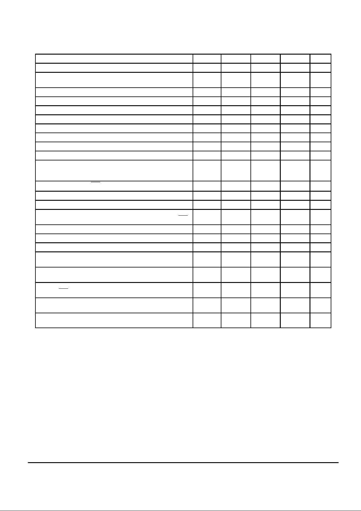
Order this document
by MC145500/D
SEMICONDUCTOR TECHNICAL DATA
L SUFFIX
CERAMIC PACKAGE
CASE 620
MC145500/03/05
P SUFFIX
PLASTIC DIP
CASE 648
MC145503/05
16
1
16
1
L SUFFIX
CERAMIC PACKAGE
CASE 726
MC145501
18
1
22
1
L SUFFIX
CERAMIC PACKAGE
CASE 736
MC145502
22
1
P SUFFIX
PLASTIC DIP
CASE 708
MC145502
DW SUFFIX
SOG PACKAGE
CASE 751G
MC145503/05
FN SUFFIX
PLCC PACKAGE
CASE 776
MC145502
16
1
28
1
Motorola, Inc. 1995
REV 1
9/95 (Replaces ADI1287)
MC145500•MC145501•MC145502•MC145503•MC145505 MOTOROLA
2
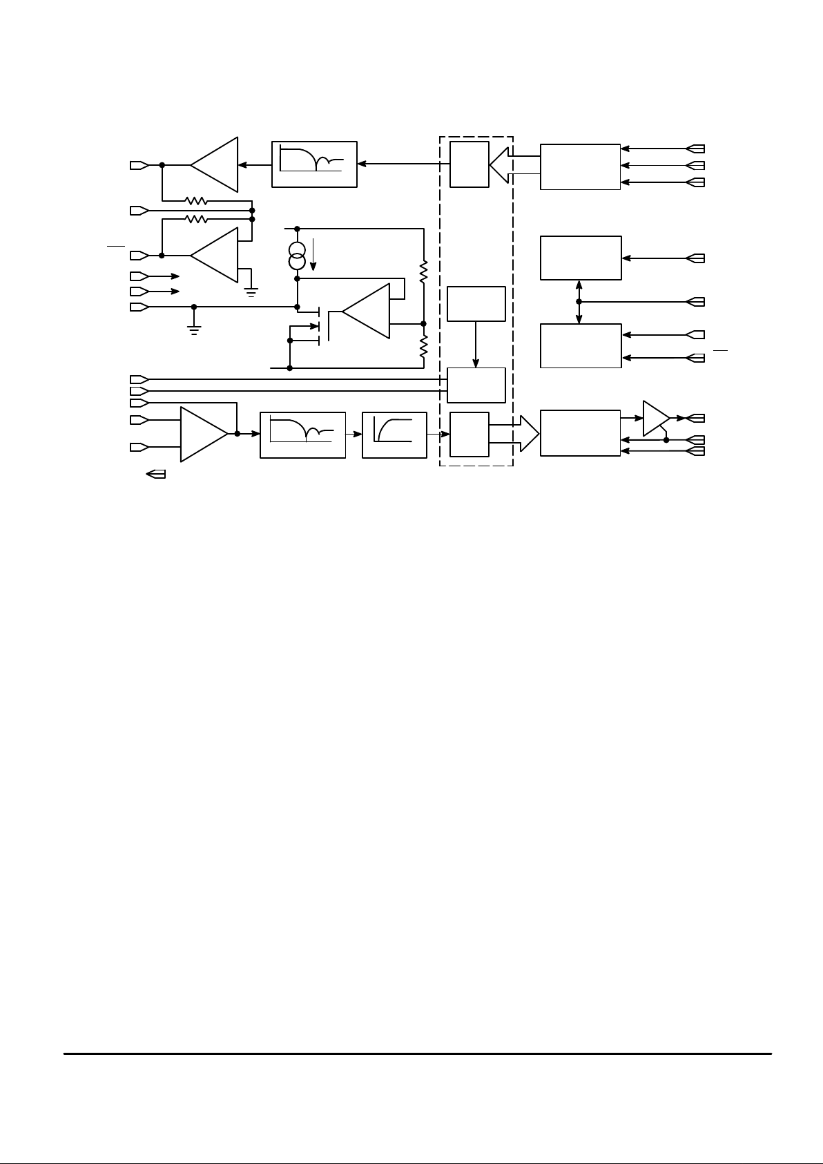
MC145500/01/02/03/05 PCM CODEC–FILTER MONO–CIRCUIT BLOCK DIAGRAM
RCE
RDC
RECEIVE SHIFT
REGISTER
D/A
SHARED
DAC
÷
1, 12, 16, 20
CCI PRESCALER
SEQUENCE
AND
CONTROL
TRANSMIT SHIFT
REGISTER
CCI
MSI
V
LS
PDI
TDD
TDE
TDC
2.5 V
REF
RSI
CIRCUITRY
A/D
FREQUENCY
FREQUENCY
FREQUENCY
Controlled by V
LS
Rx ≈
100 kΩ (internal resistors)
V
DD
V
SS
RxO
RxG
RxO
V
DD
V
SS
V
AG
V
ref
RSI
TxI
– Tx
+ Tx
Rx
Rx
400
µ
A
RDD
+
–
+
–
–
+
1
NOTES:
MC145500•MC145501•MC145502•MC145503•MC145505MOTOROLA
3
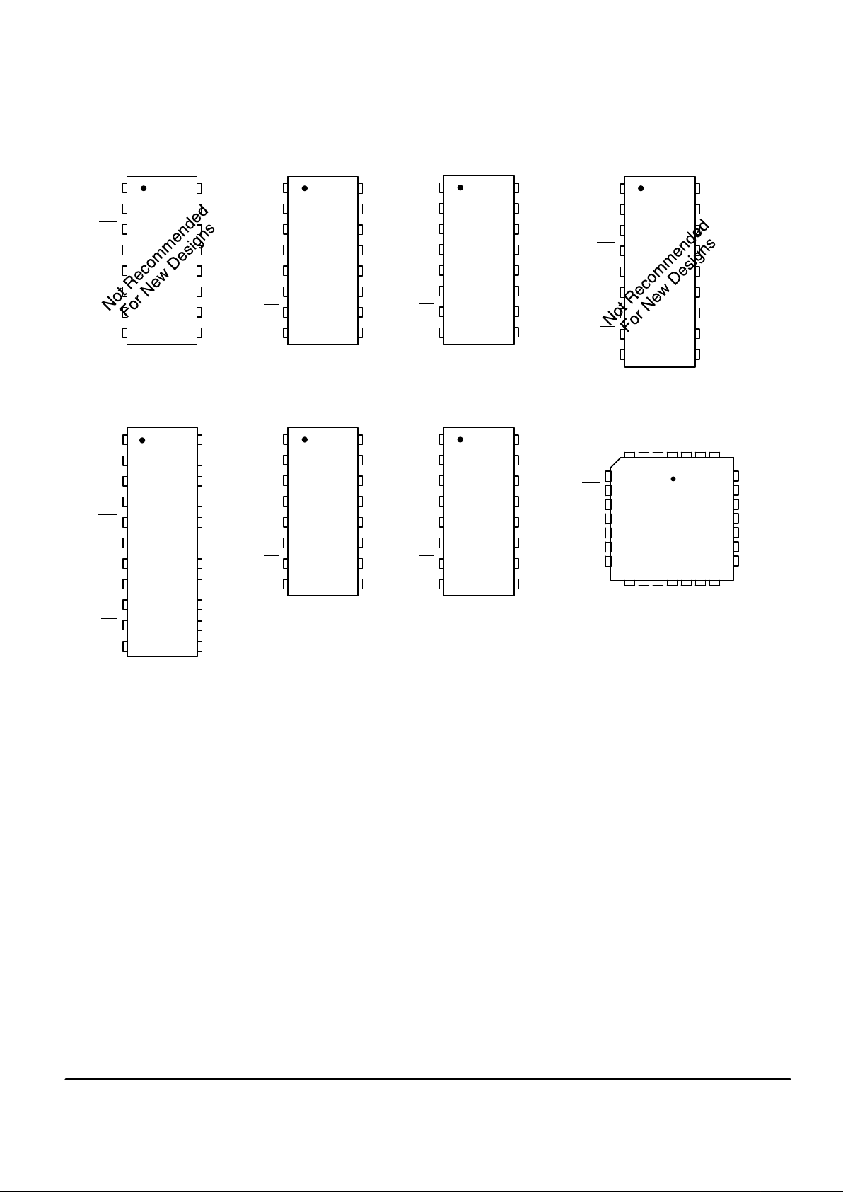
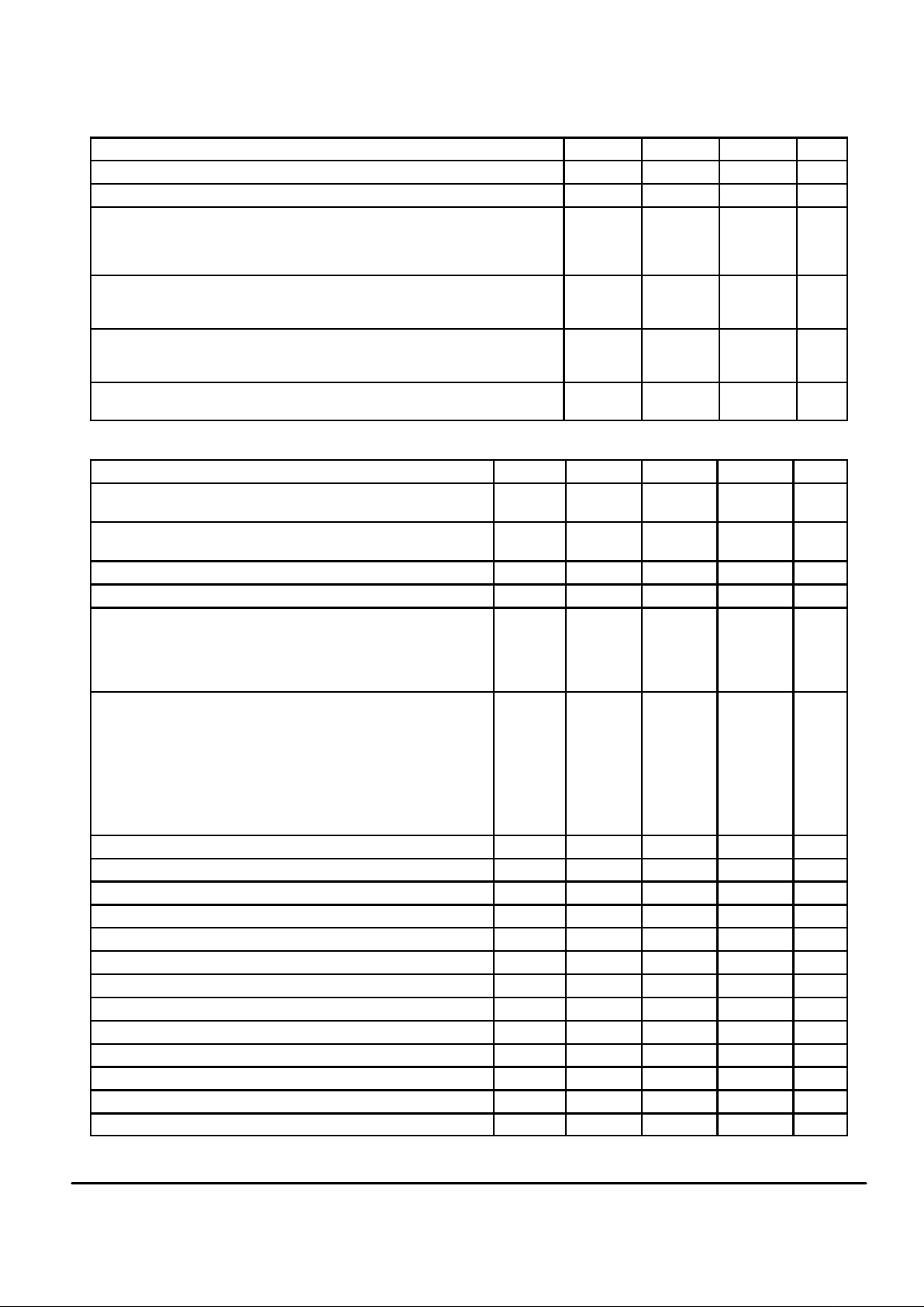
PIN ASSIGNMENTS
(DRAWINGS DO NOT REFLECT RELATIVE SIZE)
5
4
3
2
1
10
9
8
7
6
11
14
15
16
17
18
19
20
13
21
22
12
+ Tx
RxG
RxO
V
AG
V
ref
– Tx
TxI
RxO
V
SS
PDI
Mu/A
RDC
RCE
RDD
V
DD
RSI
MSI
TDE
TDD
V
LS
CCI
MC145502L, P
13
14
15
16
9
10
11
125
4
3
2
1
8
7
6
RDC
RCE
RDD
MSI
TDE
TDD
TxI
RxO
RxO
V
LS
V
SS
PDI
Mu/A
TxI
RxO
V
AG
RSI
V
SS
PDI
Mu/A
– Tx
RxO
RDC
RCE
RDD
V
DD
V
LS
MSI
TDE
TDD
TDC
14
15
16
17
18
10
11
12
13
5
4
3
2
1
9
8
7
6
MC145500L MC145501LMC145503L, P
MC145505L, P
V
AG
V
DD
TDC
MC145503DW MC145505DW
28–PIN PQLCC
(TOP VIEW)
TDC
13
14
15
16
9
10
11
125
4
3
2
1
8
7
6
RDC
RCE
RDD
V
LS
TDE
TDD
TxI
+ Tx
RxO
V
SS
PDI
Mu/A
– Tx
V
AG
V
DD
TDC
13
14
15
16
9
10
11
125
4
3
2
1
8
7
6
DCLK
RCE
RDD
V
LS
TDE
TDD
TxI
+ Tx
RxO
V
SS
PDI
Mu/A
– Tx
V
AG
V
DD
CCI
13
14
15
16
9
10
11
125
4
3
2
1
8
7
6
RDC
RCE
RDD
V
LS
TDE
TDD
TxI
+ Tx
RxO
V
SS
PDI
Mu/A
– Tx
V
AG
V
DD
TDC
13
14
15
16
9
10
11
125
4
3
2
1
8
7
6
DCLK
RCE
RDD
V
LS
TDE
TDD
TxI
+ Tx
RxO
V
SS
PDI
Mu/A
– Tx
V
AG
V
DD
CCI
4 3 2 1 28 27 26
8
7
6
10
9
11
5
19
21
22
20
23
24
25
12 13 14 15 16 17 18
+ Tx
RxO
RxG
– Tx
TxI
NC
NC
TDC
RDC
RCE
TDD
CCI
NC
NC
Mu/A
PDI
NC
MSI
TDE
V
LS
V
SS
RxO
NC
RSI
RDD
VAGV
ref
V
DD
NC = NO CONNECTION
MC145502FN

MC145500•MC145501•MC145502•MC145503•MC145505 MOTOROLA
4
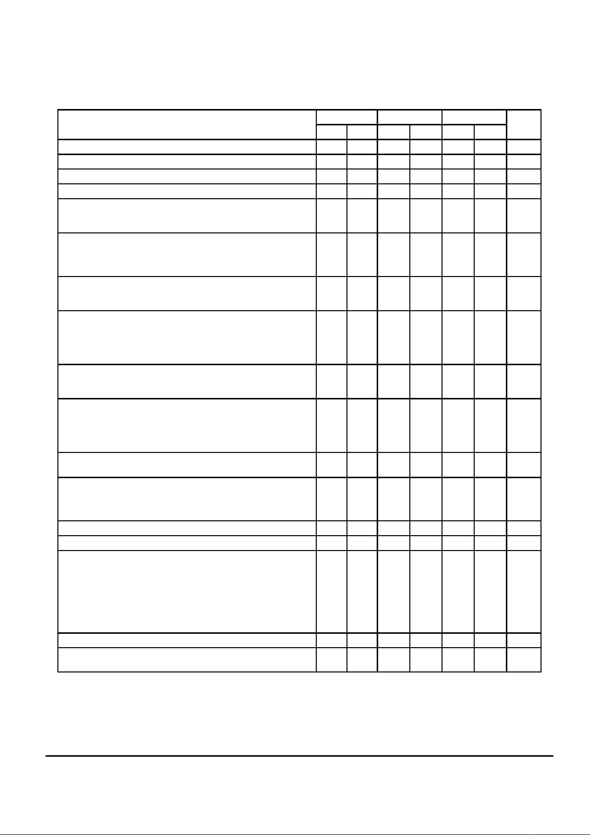
ABSOLUTE MAXIMUM RATINGS (Voltage Referenced to V
SS
)
Rating
Symbol Value Unit
DC Supply Voltage VDD, V
SS
– 0.5 to 13 V
Voltage, Any Pin to V
SS
V – 0.5 to VDD + 0.5 V
DC Drain Per Pin (Excluding VDD, VSS) I 10 mA
Operating Temperature Range T
A
– 40 to + 85 °C
Storage Temperature Range T
stg
– 85 to + 150 °C
RECOMMENDED OPERATING CONDITIONS (T
A
= – 40 to + 85°C)
Characteristic
Min Typ Max Unit
DC Supply Voltage
Dual Supplies: VDD = – VSS, (VAG = VLS = 0 V)
Single Supply: VDD to VSS (VAG is an Output, VLS = VDD or VSS)
MC145500, MC145501, MC145502, MC145503, MC145505 (Using Internal
3.15 V Reference)
MC145501, MC145502 Using Internal 2.5 V Reference
MC145501, MC145502 Using Internal 3.78 V Reference
MC145502 Using External 1.5 V Reference, Referenced to V
AG
4.75
8.5
7.0
9.5
4.75
5.0
—
—
—
—
6.3
12.6
12.6
12.6
12.6
V
Power Dissipation
CMOS Logic Mode (VDD to VSS = 10 V, VLS = VDD)
TTL Logic Mode (VDD = + 5 V, VSS = – 5 V, VLS = VAG = 0 V)
—
—
40
50
70
90
mW
Power Down Dissipation — 0.1 1.0 mW
Frame Rate Transmit and Receive 7.5 8.0 8.5 kHz
Data Rate
MC145500, MC145501, MC145503
Must Use One of These Frequencies, Relative to MSI Frequency of 8 kHz
—
—
—
—
—
128
1536
1544
2048
2560
—
—
—
—
—
kHz
Data Rate for MC145502, MC145505 64 — 4096 kHz
Full Scale Analog Input and Output Level
MC145500, MC145503, MC145505
MC145501, MC145502 (V
ref
= VSS) RSI = V
DD
RSI = V
SS
RSI = V
AG
MC145502 Using an External Reference Voltage Applied at V
ref
Pin RSI = V
DD
RSI = V
SS
RSI = V
AG
—
—
—
—
—
—
—
3.15
3.78
3.15
2.5
1.51 x V
ref
1.26 x V
ref
V
ref
—
—
—
—
—
—
—
Vp
DIGITAL LEVELS (V
SS
to VDD = 4.75 V to 12.6 V, TA = – 40 to + 85°C)
Characteristic
Symbol Min Max Unit
Input Voltage Levels (TDE, TDC, RCE, RDC, RDD, DC, MSI, CCI, PDI)
CMOS Mode (VLS = VDD, VSS is Digital Ground) “0”
“1”
TTL Mode (VLS ≤
V
DD
– 4.0 V, VLS is Digital Ground) “0”
“1”
V
IL
V
IH
V
IL
V
IH
—
0.7 x V
DD
—
VLS + 2.0 V
0.3 x V
DD
—
VLS + 0.8 V
—
V
Output Current for TDD (Transmit Digital Data)
CMOS Mode (VLS = VDD, VSS = 0 V and is Digital Ground)
(VDD = 5 V, V
out
= 0.4 V)
(VDD = 10 V, V
out
= 0.5 V)
(VDD = 5 V, V
out
= 4.5 V)
(VDD = 10 V, V
out
= 9.5 V)
TTL Mode (VLS ≤
V
DD
– 4.75 V, VLS = 0 V and is Digital Ground) (VOL = 0.4 V)
(VOH = 2.4 V)
I
OL
I
OH
I
OL
I
OH
1.0
3.0
– 1.0
– 3.0
1.6
– 0.2
—
—
—
—
—
—
mA
This device contains circuitry to protect
against damage due to high static voltages or
electric fields; however, it is advised that
normal precautions be taken to avoid application of any voltage higher than maximum rated
voltages to this high impedance circuit. For
proper operation it is recommended that V
in
and V
out
be constrained to the range VSS ≤ (V
in
or V
out
) ≤ VDD.
Unused inputs must always be tied to an
appropriate logic voltage level (e.g., VSS, VDD,
VLS, or VAG).
MC145500•MC145501•MC145502•MC145503•MC145505MOTOROLA
5
ANALOG TRANSMISSION PERFORMANCE
(VDD = + 5 V ± 5%, VSS = – 5 V ± 5%, VLS = VAG = 0 V, V
ref
= RSI = VSS (Internal 3.15 V Reference), 0 dBm0 = 1.546 Vrms = + 6 dBm @
600 Ω, TA = – 40 to + 85°C, TDC = RDC = CC = 2.048 MHz, TDE = RCE = MSI = 8 kHz, Unless Otherwise Noted)
End–to–End A/D D/A
Characteristic
Min Max Min Max Min Max Unit
Absolute Gain (0 dBm0 @ 1.02 kHz, TA = 25°C, VDD = 5 V, VSS = – 5 V) — — – 0.30 + 0.30 – 0.30 + 0.30 dB
Absolute Gain Variation with Temperature 0 to + 70°C — — — ± 0.03 — ± 0.03 dB
Absolute Gain Variation with Temperature – 40 to +85°C — — — ± 0.1 — ± 0.1 dB
Absolute Gain Variation with Power Supply (VDD = 5 V, VSS = – 5 V, 5%) — — — ± 0.02 — ± 0.02 dB
Gain vs Level Tone (Relative to – 10 dBm0, 1.02 kHz) + 3 to – 40 dBm0
– 40 to – 50 dBm0
– 50 to – 55 dBm0
– 0.4
– 0.8
– 1.6
+ 0.4
+ 0.8
+ 1.6
– 0.2
– 0.4
– 0.8
+ 0.2
+ 0.4
+ 0.8
– 0.2
– 0.4
– 0.8
+ 0.2
+ 0.4
+ 0.8
dB
Gain vs Level Pseudo Noise (A–Law Relative to – 10 dBm0)
CCITT G.714 – 10 to – 40 dBm0
– 40 to – 50 dBm0
– 50 to – 55 dBm0
—
—
—
—
—
—
– 0.25
– 0.30
– 0.45
+ 0.25
+ 0.30
+ 0.45
– 0.25
– 0.30
– 0.45
+ 0.25
+ 0.30
+ 0.45
dB
Total Distortion – 1.02 kHz Tone (C–Message) 0 to – 30 dBm0
– 40 dBm0
– 45 dBm0
35
29
24
—
—
—
36
29
24
—
—
—
36
30
25
—
—
—
dBC
Total Distortion With Pseudo Noise (A–Law) – 3 dBm0
CCITT G.714 – 6 to – 27 dBm0
– 34 dBm0
– 40 dBm0
– 55 dBm0
27.5
35
33.1
28.2
13.2
—
—
—
—
—
28
35.5
33.5
28.5
13.5
—
—
—
—
—
28.5
36
34.2
30.0
15.0
—
—
—
—
—
dB
Idle Channel Noise (For End–End and A/D, See Note 1)
Mu–Law, C–Message Weighted
A–Law, Psophometric Weighted
—
—15– 69——
15
– 69
—
—
9
– 78
dBrnC0
dBm0p
Frequency Response (Relative to 1.02 kHz @ 0 dBm0) 15 to 60 Hz
300 to 3000 Hz
3400 Hz
4000 Hz
≥ 4600 Hz
—
– 0.3
– 1.6
—
—
– 23
+ 0.3
0
– 28
– 60
—
– 0.15
– 0.8
—
—
– 23
+ 0.15
0
– 14
– 32
—
– 0.15
– 0.8
—
—
0.15
+ 0.15
0
– 14
– 30
dB
Inband Spurious (1.02 kHz @ 0 dBm0, Transmit and RxO)
300 to 3000 Hz
— — — – 43 — – 43 dBm0
Out–of–Band Spurious at RxO (300 – 3400 Hz @ 0 dBm0 In)
4600 to 7600 Hz
7600 to 8400 Hz
8400 to 100,000 Hz
—
—
—
– 30
– 40
– 30
—
—
—
—
—
—
—
—
—
– 30
– 40
– 30
dB
Idle Channel Noise Selective @ 8 kHz, Input = VAG, 30 Hz Bandwidth — – 70 — — — – 70 dBm0
Absolute Delay @ 1600 Hz (TDC = 2.048 MHz, TDE = 8 kHz) — — — 310 — 180 µs
Group Delay Referenced to 1600 Hz (TDC = 2048 kHz,
TDE = 8 kHz) 500 to 600 Hz
600 to 800 Hz
800 to 1000 Hz
1000 to 1600 Hz
1600 to 2600 Hz
2600 to 2800 Hz
2800 to 3000 Hz
—
—
—
—
—
—
—
—
—
—
—
—
—
—
—
—
—
—
—
—
—
200
140
70
40
75
110
170
– 40
– 40
– 30
– 20
—
—
—
—
—
—
—
90
120
160
µs
Crosstalk of 1020 Hz @ 0 dBm0 From A/D or D/A (Note 2) — — — – 75 — – 80 dB
Intermodulation Distortion of Two Frequencies of Amplitudes – 4 to
– 21 dBm0 from the Range 300 to 3400 Hz
— — — – 41 — – 41 dB
NOTES:
1. Extrapolated from a 1020 Hz @ – 50 dBm0 distortion measurement to correct for encoder enhancement.
2. Selectively measured while the A/D is stimulated with 2667 Hz @ – 50 dBm0.
MC145500•MC145501•MC145502•MC145503•MC145505 MOTOROLA
6
ANALOG ELECTRICAL CHARACTERISTICS (V
DD
= – VSS = 5 V to 6 V ± 5%, TA = – 40 to + 85°C)
Characteristic Symbol Min Typ Max Unit
Input Current +Tx, –Tx (Txl for MC145500) I
in
— ± 0.01 ± 0.2 µA
AC Input Impedance to VAG (1 kHz) +Tx, –Tx
Txl for MC145500
Z
in
5
0.1
10
0.2
—
—
MΩ
Input Capacitance +Tx, –Tx — — 10 pF
Input Offset Voltage of Txl Op Amp — < ± 30 — mV
Input Common Mode Voltage Range +Tx, –Tx V
ICR
VSS + 1.0 — VDD – 2.0 V
Input Common Mode Rejection Ratio +Tx, –Tx CMRR — 70 — dB
Txl Unity Gain Bandwidth RL ≥ 10 kΩ BW
p
— 1000 — kHz
Txl Open Loop Gain RL ≥ 10 kΩ A
VOL
— 75 — dB
Equivalent Input Noise (C–Message) Between +Tx and –Tx, at Txl — – 20 — dBrnC0
Output Load Capacitance for Txl Op Amp 0 — 100 pF
Output Voltage Range Txl Op Amp, RxO or RxO
RL = 10 kΩ to V
AG
RL = 600 Ω to V
AG
V
out
VSS + 0.8
VSS + 1.5
—
—
VDD – 1.0
VDD – 1.5
V
Output Current Txl, RxO, RxO VSS + 1.5 V ≤ V
out
≤ VDD – 1.5 V
± 5.5 — — mA
Output Impedance RxO, RxO* 0 to 3.4 kHz Z
out
— 3 — Ω
Output Load Capacitance for RxO and RxO* 0 — 200 pF
Output dc Offset Voltage Referenced to VAG Pin RxO
RxO
*
—
—
—
—
± 100
± 150
mV
Internal Gainsetting Resistors for RxG to RxO and RxO 62 100 225 kΩ
External Reference Voltage Applied to V
ref
(Referenced to VAG) 0.5 — VDD – 1.0 V
V
ref
Input Current — — 20 µA
VAG Output Bias Voltage — 0.53 VDD +
0.47 V
SS
— V
VAG Output Current Source
Sink
I
VAG
0.4
10.0
—
—
0.8
—
mA
Output Leakage Current During Power Down for the Txl Op Amp, VAG,
RxO, and RxO
— — ± 30 µA
Positive Power Supply Rejection Ratio, Transmit
0 – 100 kHz @ 250 mV, C–Message Weighting Receive
45
55
50
65
—
—
dBC
Negative Power Supply Rejection Ratio, Transmit
0 – 100 kHz @ 250 mV, C–Message Weighting Receive
50
50
55
60
—
—
dBC
*Assumes that RxG is not connected for gain modifications to RxO.
MC145500•MC145501•MC145502•MC145503•MC145505MOTOROLA
7
MODE CONTROL LOGIC (V
SS
to VDD = 4.75 V to 12.6 V, TA = – 40 to + 85°C)
Characteristic
Min Typ Max Unit
VLS Voltage for TTL Mode (TTL Logic Levels Referenced to VLS) V
SS
— VDD – 4.0 V
VLS Voltage for CMOS Mode (CMOS Logic Levels of VSS to VDD) VDD – 0.5 — V
DD
V
Mu/A Select Voltage
Mu–Law Mode
Sign Magnitude Mode
A–Law Mode
VDD – 0.5
VAG – 0.5
V
SS
—
—
—
V
DD
VAG + 0.5
VSS + 0.5
V
RSI Voltage for Reference Select Input (MC145501 and MC145502) 3.78 V Mode
2.5 V Mode
3.15 V Mode
VDD – 0.5
VAG – 0.5
V
SS
—
—
—
V
DD
VAG + 0.5
VSS + 0.5
V
V
ref
Voltage for Internal or External Reference (MC145502 Only)
Internal Reference Mode
External Reference Mode
V
SS
VAG + 0.5
—
—
VSS + 0.5
VDD – 1.0
V
Analog Test Mode Frequency, MS = CCI (MC145500, MC145501, MC145502 Only)
See Pin Description; Test Modes
— 128 — kHz
SWITCHING CHARACTERISTICS (V
SS
to VDD = 9.5 V to 12.6 V, TA = – 40 to + 85°C, CL = 150 pF, CMOS or TTL Mode)
Characteristic
Symbol Min Typ Max Unit
Output Rise Time TDD
Output Fall Time
t
TLH
t
THL
—
—
30
30
80
80
ns
Input Rise Time TDE, TDC, RCE, RDC, DC, MSI, CCI
Input Fall Time
t
TLH
t
THL
—
—
—
—
4
4
µs
Pulse Width TDE Low, TDC, RCE, RDC, DC, MSI, CCI t
w
100 — — ns
DCLK Pulse Frequency (MC145502/05 Only) TDC, RDC, DC f
CL
64 — 4096 kHz
CCI Clock Pulse Frequency (MSI = 8 kHz)
CCI is internally tied to TDC on the MC145500/01/03, therefore, the
transmit data clock must be one of these frequencies. This pin will accept
one of these discrete clock frequencies and will compensate to produce
internal sequencing.
f
CL1
f
CL2
f
CL3
f
CL4
f
CL5
—
—
—
—
—
128
1536
1544
2048
2560
—
—
—
—
—
kHz
Propagation Delay Time
TDE Rising to TDD Low Impedance TTL
CMOS
TDE Falling to TDD High Impedance TTL
CMOS
TDC Rising Edge to TDD Data, During TDE High TTL
CMOS
TDE Rising Edge to TDD Data, During TDC High TTL
CMOS
t
P1
t
P2
t
P3
t
P4
—
—
—
—
—
—
—
—
90
90
—
—
90
90
90
90
180
150
55
40
180
150
180
150
ns
TDC Falling Edge to TDE Rising Edge Setup Time t
su1
20 — — ns
TDE Rising Edge to TDC Falling Edge Setup Time t
su2
100 — — ns
TDE Falling Edge to TDC Rising Edge to Preserve the Next TDD Data t
su8
20 — — ns
RDC Falling Edge to RCE Rising Edge Setup Time t
su3
20 — — ns
RCE Rising Edge to RDC Falling Edge Setup Time t
su4
100 — — ns
RDD Valid to RDC Falling Edge Setup Time t
su5
60 — — ns
CCI Falling Edge to MSI Rising Edge Setup Time t
su6
20 — — ns
MSI Rising Edge to CCI Falling Edge Setup Time t
su7
100 — — ns
RDD Hold Time from RDC Falling Edge t
h
100 — — ns
TDE, TDC, RCE, RDC, RDD, DC, MSI, CCI Input Capacitance — — 10 pF
TDE,TDC, RCE, RDC, RDD, DC, MSI, CCI Input Current — ± 0.01 ± 10 µA
TDD Capacitance During High Impedance (TDE Low) — 12 15 pF
TDD Input Current During High Impedance (TDE Low) — ± 0.1 ± 10.0 µA

MC145500•MC145501•MC145502•MC145503•MC145505 MOTOROLA
8
DEVICE DESCRIPTIONS
A codec–filter is a device which is used for digitizing and
reconstructing the human voice. These devices were developed primarily for the telephone network to facilitate voice
switching and transmission. Once the voice is digitized, it
may be switched by digital switching methods or transmitted
long distance (T1, microwave, satellites, etc.) without degradation. The name codec is an acronym from “Coder” for the
A/D used to digitize voice, and “Decoder” for the D/A used for
reconstructing voice. A codec is a single device that does
both the A/D and D/A conversions.
To digitize intelligible voice requires a signal to distortion of
about 30 dB for a dynamic range of about 40 dB. This may be
accomplished with a linear 13–bit A/D and D/A, but will far
exceed the required signal to distortion at amplitudes greater
than 40 dB below the peak amplitude. This excess performance is at the expense of data per sample. Two methods of
data reduction are implemented by compressing the 13–bit
linear scheme to companded 8–bit schemes. These companding schemes follow a segmented or “piecewise–linear”
curve formatted as sign bit, three chord bits, and four step
bits. For a given chord, all 16 of the steps have the same voltage weighting. As the voltage of the analog input increases,
the four step bits increment and carry to the three chord bits
which increment. With the chord bits incremented, the step
bits double their voltage weighting. This results in an effective resolution of 6–bits (sign + chord + four step bits) across
a 42 dB dynamic range (7 chords above zero, by 6 dB per
chord). There are two companding schemes used; Mu–255
Law specifically in North America, and A–Law specifically in
Europe. These companding schemes are accepted world
wide. The tables show the linear quantization levels to PCM
words for the two companding schemes.
In a sampling environment, Nyquist theory says that to
properly sample a continuous signal, it must be sampled at a
frequency higher than twice the signal’s highest frequency
component. Voice contains spectral energy above 3 kHz, but
its absence is not detrimental to intelligibility. To reduce the
digital data rate, which is proportional to the sampling rate, a
sample rate of 8 kHz was adopted, consistent with a bandwidth of 3 kHz. This sampling requires a low–pass filter to
limit the high frequency energy above 3 kHz from distorting
the i nband signal. T he telephone line is a lso subject to
50/60 Hz power line coupling which must be attenuated from
the signal by a high–pass filter before the A/D converter.
The D/A process reconstructs a staircase version of the
desired inband signal which has spectral images of the inband signal modulated about the sample frequency and its
harmonics. These spectral images are called aliasing components which need to be attenuated to obtain the desired
signal. The low–pass filter used to attenuate filter aliasing
components is typically called a reconstruction or smoothing
filter.
The MC145500 series PCM Codec–Filters have the codec, both presampling and reconstruction filters, a precision
voltage reference on chip, and require no external components. There a re five distinct versions o f the Motorola
MC145500 Series.
MC145500
The MC145500 PCM Codec–Filter is intended for standard byte interleaved synchronous and asynchronous applications. The TDC pin on this device is the input to both the
TDC and CCI functions in the pin description. Consequently,
for MSI = 8 kHz, TDC can be one of five discrete frequencies.
These are 128 kHz (40 to 60% duty cycle) 1.536, 1.544,
2.048, or 2.56 MHz. (For other data clock frequencies, see
MC145502 or MC145505.) The internal reference is set for
3.15 V peak full scale, and the full scale input level at Txl and
output level at RxO is 6 .3 V peak–to–peak. This is the
+ 3 dBm0 level of the PCM Codec–Filter. All other functions
are described in the pin description.
MC145501
The MC145501 PCM Codec–Filter offers the same features and is for the same application as the MC145500, but
offers two additional pins and features. The reference select
input allows the full s cale level of the device to be set at
2.5 Vp, 3.15 Vp, or 3.78 Vp. The –Tx pin allows for external
transmit g ain adjust a nd simplifies the i nterface t o the
MC3419 SLIC. Otherwise, it is identical to MC145500.
MC145502
The MC145502 P CM Codec–Filter is the full f eature
22–pin device. It is intended for use in applications requiring
maximum flexibility. The MC145502 contains all the features
of the M C145500 and M C145501. The M C145502 is intended for bit interleaved or byte interleaved applications
with data clock frequencies which are nonstandard or time
varying. One of the five standard frequencies (listed above)
is applied to the CCI input, and the data clock inputs can be
any frequency between 64 kHz and 4.096 MHz. The V
ref
pin
allows for use of an external shared reference or selection of
the internal reference. The RxG pin accommodates gain adjustments for the inverted analog output. All three pins of the
input gain–setting operational amplifier are present, providing maximum flexibility for the analog interface.
MC145503
The MC145503 PCM Codec–Filter is intended for standard byte interleaved synchronous or asynchronous applications. TDC can be one of five discrete frequencies. These
are 128 kHz (40 to 60% duty cycle), 1.536, 1.544, 2.048, or
2.56 MHz. (For other data clock frequencies, see MC145502
or MC145505.) The internal reference is set for 3.15 V peak
full scale, and the full scale input level at Txl and output level
at RxO is 6.3 V peak–to–peak. This is the + 3 dBm0 level of
the PCM Codec–Filter. The +Tx and –Tx inputs provide maximum flexibility for analog interface. All other functions are
described in the pin description.
MC145505
The MC145505 PCM Codec–Filter is intended for byte interleaved synchronous applications. The MC145505 has all
the features of the MC145503 but internally connects TDC
and RDC (see pin description) to the DC pin. One of the five
standard frequencies (listed above) should be applied to

MC145500•MC145501•MC145502•MC145503•MC145505MOTOROLA
9
CCI. The data clock input (DC) can be any frequency between 64 kHz and 4.096 MHz.
PIN DESCRIPTIONS
DIGITAL
V
LS
Logic Level Select input and TTL Digital Ground
VLS controls the logic levels and digital ground reference
for all digital inputs and the digital output. These devices can
operate with logic levels from full supply (VSS to VDD) or
with TTL logic levels using VLS as digital ground. For VLS =
VDD, all I/O is full supply (VSS to VDD swing) with CMOS
switch points. For VSS < VLS < (VDD – 4 V), all inputs and
outputs are TTL compatible with VLS being the digital ground.
The pins controlled by VLS are inputs MSI, CCI, TDE, TDC,
RCE, RDC, RDD, PDI
, and output TDD.
MSI
Master Synchronization Input
MSI is used for determining the sample rate of the transmit
side and as a time base for selecting the internal prescale
divider for the convert clock input (CCI) pin. The MSI pin
should be tied to an 8 kHz clock which may be a frame sync
or system sync signal. MSI has no relation t o transmit or
receive data timing, except for determining the internal transmit strobe as described under the TDE pin description. MSI
should be derived from the transmit timing in asynchronous
applications. In many applications MSI can be tied to TDE.
(MSI is tied internally to TDE in MC145503/05.)
CCI
Convert Clock Input
CCI is designed to accept five discrete clock frequencies.
These are 128 kHz, 1.536 MHz, 1.544 MHz, 2.048 MHz, or
2.56 MHz. The frequency at this input is compared with MSI
and prescale divided to produce the internal s equencing
clock at 128 kHz (or 16 times the sampling rate). The duty
cycle of CCI is dictated by the minimum pulse width except
for 128 kHz, which is used directly for internal sequencing
and must have a 40 to 60% duty cycle. In asynchronous
applications, CCI should be derived from transmit timing.
(CCI is tied internally to TDC in MC145500/01/03.)
TDC
Transmit Data Clock Input
TDC can be any frequency from 64 kHz to 4.096 MHz, and
is often tied to CCI if the data rate is equal to one of the five
discrete frequencies. This clock is t he shift clock for the
transmit shift register and its rising edges produce successive data bits at TDD. TDE should be derived from this clock.
(TDC and RDC are tied together internally in the MC145505
and are c alled DC.) CCI is internally tied to TDC on t he
MC145500/ 01/03. Therefore, TDC must satisfy CCI timing
requirements also.
TDE
Transmit Data Enable Input
TDE serves three major functions. The first TDE rising
edge following an MSI rising edge generates the internal
transmit strobe which initiates an A/D conversion. The internal transmit strobe also transfers a new PCM data word into
the transmit shift register (sign bit first) ready to be output at
TDD. The TDE pin is the h igh impedance control for the
transmit digital data (TDD) output. As long as this pin is high,
the TDD output stays low impedance. This pin also enables
the output shift register for clocking out the 8–bit serial PCM
word. T he logical A ND of the TDE pin with the TDC pin
clocks out a new data bit at TDD. TDE should be held high
for eight consecutive TDC cycles to clock out a complete
PCM word for byte interleaved applications. The transmit
shift register feeds back on itself to allow multiple reads of
the transmit data. If the PCM word is clocked out once per
frame in a byte interleaved system, the MSI pin function is
transparent and may be connected to TDE.
The TDE pin may be cycled during a PCM word for bit interleaved applications. TDE controls both the high impedance state of the TDD output and the internal shift clock. TDE
must fall before TDC rises (t
su8
) to ensure integrity of the
next data bit. There must be at least two TDC falling edges
between the last TDE rising edge of one frame and the first
TDE rising edge of the next frame. MSI must be available
separate from TDE for bit interleaved applications.
TDD
Transmit Digital Data Output
The output levels at t his pin are controlled by the V
LS
pin. For VLS connected to VDD, the output levels are from
VSS to VDD. For a voltage of VLS between VDD – 4 V and VSS,
the output levels are TTL compatible with VLS being the digital g round supply. The TDD p in is a three–state o utput
controlled by the TDE pin. The timing of this pin is controlled
by TDC and TDE. When in TTL mode, this output may be
made high–speed CMOS compatible using a pull–up resistor. The data format (Mu–Law, A–Law, or sign magnitude) is
controlled by the Mu/A pin.
RDC
Receive Data Clock Input
RDC can be any frequency from 64 kHz to 4.096 MHz.
This pin is often tied to the TDC pin for applications that can
use a common clock for both transmit and receive data transfers. The receive shift register is controlled by the receive
clock enable (RCE) pin to clock data into the receive digital
data (RDD) pin on falling RDC edges. These three signals
can be asynchronous with all other digital pins. The RDC input is internally tied to the TDC input on the MC145505 and
called DC.
RCE
Receive Clock Enable Input
The rising edge of RCE should identify the sign bit of a receive PCM word on RDD. The next falling edge of RDC, after
a rising RCE, loads the first bit of the PCM word into the receive register. The next seven falling edges enter the remainder of the PCM word. On the ninth rising edge, the receive
PCM word is transferred to the receive buffer register and the
A/D sequence is interrupted to commence the decode process. In asynchronous applications with an 8 kHz transmit
sample rate, the receive sample rate should be between 7.5
and 8.5 kHz. Two receive PCM words may be decoded and
analog summed each transmit frame to allow on–chip conferencing. The two PCM words should be clocked in as two
single PCM words, a m inimum of 31.25 µs apart, with a
receive data clock of 512 kHz or faster.
 Loading...