


Cleartone CM5000
TETRA Mobile Repeater/Gateway
380 - 430 MHz (MT912CR)
Basic Service Manual
Part Number: 6866539D44-A
@6866539D44@
GCD-EMEA, Issued: 11.2007

ii CM5000 Mobile Terminal / Basic Service Manual COPYRIGHT
COPYRIGHT
Copyrights
© 2001 - 2007 Motorola Inc. All rights reserved.
No part of this manual may be reproduced, transmitted, stored in a retrieval system, or
translated into any language or computer language, in any form or by any means, without
the prior written permission of Motorola Inc.
Computer Software Copyrights
The Motorola products described in this manual may include copyrighted Motorola computer programs stored in semiconductor memories or other media. Laws in the United
States and other countries preserve for Motorola certain exclusive rights for copyrighted
computer programs including, but not limited to, the exclusive right to copy or reproduce in
any form the copyrighted computer program. Accordingly, any copyrighted Motorola computer programs contained in the Motorola products described in this manual may not be
copied, reproduced, modified, reverse-engineered, or distributed in any manner without the
express written permission of Motorola. Furthermore, the purchase of Motorola products
shall not be deemed to grant either directly or by implication, estoppel, or otherwise, any
license under the copyrights, patents or patent applications of Motorola, except for the normal non-exclusive royalty-free license to use that arises by operation of law in the sale of a
product.
Trademarks
Motorola, the Motorola Logo and all other trademarks identified as such herein are trademarks of Motorola Inc. All other product or service names are the property of their respective owners.

CONTENTS CM5000 Mobile Terminal / Detailed Service Manual iii
CONTENTS
COPYRIGHT . . . . . . . . . . . . . . . . . . . . . . . . . . . . . . . . . . . . . . . . . . . . . . . . . . . . . . . . . II
Copyrights . . . . . . . . . . . . . . . . . . . . . . . . . . . . . . . . . . . . . . . . . . . . . . . . . . . . ii
Computer Software Copyrights . . . . . . . . . . . . . . . . . . . . . . . . . . . . . . . . . . . ii
Trademarks . . . . . . . . . . . . . . . . . . . . . . . . . . . . . . . . . . . . . . . . . . . . . . . . . . . . ii
CONTENTS . . . . . . . . . . . . . . . . . . . . . . . . . . . . . . . . . . . . . . . . . . . . . . . . . . . . . . . . . . III
DOCUMENT HISTORY . . . . . . . . . . . . . . . . . . . . . . . . . . . . . . . . . . . . . . . . . . . . . . . . . V
PRODUCT SAFETY AND RF ENERGY EXPOSURE . . . . . . . . . . . . . . . . . . . . . . . . . VII
RF Energy Exposure Awareness and Control Information, and Operational
Instructions for FCC Occupational Use Requirements. . . . . . . . . . . . . . . . . vii
Federal Communications Commission Regulations (US markets only) . . . . viii
Compliance with RF Exposure Standard . . . . . . . . . . . . . . . . . . . . . . . . . . . viii
Your Motorola two-way terminal complies with the following RF energy exposure
standards and guidelines: . . . . . . . . . . . . . . . . . . . . . . . . . . . . . . . . . . . . . . viii
RF Exposure Compliance and Control Guidelines and Operating Instructions .ix
Mobile Antenna Installation Guidelines . . . . . . . . . . . . . . . . . . . . . . . . . . . . . x
Approved Accessories . . . . . . . . . . . . . . . . . . . . . . . . . . . . . . . . . . . . . . . . . . x
Additional Information . . . . . . . . . . . . . . . . . . . . . . . . . . . . . . . . . . . . . . . . . . x
Compliance and Control Guidelines and Operating Instructions for Mobile Two-
Way Terminals Installed as Fixed Site Control Stations . . . . . . . . . . . . . . . . . x
Electromagnetic Interference/Compatibility . . . . . . . . . . . . . . . . . . . . . . . . . .xi
Facilities . . . . . . . . . . . . . . . . . . . . . . . . . . . . . . . . . . . . . . . . . . . . . . . . . . . . .xi
Vehicles . . . . . . . . . . . . . . . . . . . . . . . . . . . . . . . . . . . . . . . . . . . . . . . . . . . . .xi
Driver Safety . . . . . . . . . . . . . . . . . . . . . . . . . . . . . . . . . . . . . . . . . . . . . . . . .xi
OPERATIONAL WARNINGS . . . . . . . . . . . . . . . . . . . . . . . . . . . . . . . . . . . . . . xii
For Vehicles With Air Bags . . . . . . . . . . . . . . . . . . . . . . . . . . . . . . . . . . . . . . xii
Potentially Explosive Atmospheres . . . . . . . . . . . . . . . . . . . . . . . . . . . . . . . xii
Blasting Caps And Blasting Areas . . . . . . . . . . . . . . . . . . . . . . . . . . . . . . . . xii
ADDITIONAL IMPORTANT INFORMATION
FOR SERVICING AND INSTALLING THE TERMINAL . . . . . . . . . . . . . . . . xiii
ZUSÄTZLICHE SICHERHEITSINFORMATIONEN FÜR SERVICE UND
INSTALLATION DES FUNKGERÄTES . . . . . . . . . . . . . . . . . . . . . . . . . . . . . xiii
CHAPTER 1
SCOPE & WARRANTY INFORMATION . . . . . . . . . . . . . . . . . . . . . . . . . . . . . . . . . . . . 1
Scope of this manual . . . . . . . . . . . . . . . . . . . . . . . . . . . . . . . . . . . . . . . . . . . . 1
Manuals & User Guides . . . . . . . . . . . . . . . . . . . . . . . . . . . . . . . . . . . . . . . . . 2
Warranty . . . . . . . . . . . . . . . . . . . . . . . . . . . . . . . . . . . . . . . . . . . . . . . . . . . . . . 2

iv MTM800 Mobile Terminal / Basic Service Manual CONTENTS
CHAPTER 2
MODEL INFORMATION . . . . . . . . . . . . . . . . . . . . . . . . . . . . . . . . . . . . . . . . . . . . . . . . . 5
CM5000 Model Information . . . . . . . . . . . . . . . . . . . . . . . . . . . . . . . . . . . . . . . 5
Features . . . . . . . . . . . . . . . . . . . . . . . . . . . . . . . . . . . . . . . . . . . . . . . . . . . . . 5
Technical Specifications . . . . . . . . . . . . . . . . . . . . . . . . . . . . . . . . . . . . . . . . . 6
Feature Specification . . . . . . . . . . . . . . . . . . . . . . . . . . . . . . . . . . . . . . . . . . .7
CHAPTER 3
OVERVIEW . . . . . . . . . . . . . . . . . . . . . . . . . . . . . . . . . . . . . . . . . . . . . . . . . . . . . . . . . . . 9
General . . . . . . . . . . . . . . . . . . . . . . . . . . . . . . . . . . . . . . . . . . . . . . . . . . . . . . . 9
Digital Control Circuit . . . . . . . . . . . . . . . . . . . . . . . . . . . . . . . . . . . . . . . . . . . 9
Radio Circuit . . . . . . . . . . . . . . . . . . . . . . . . . . . . . . . . . . . . . . . . . . . . . . . . . . 15
Key and display Unit . . . . . . . . . . . . . . . . . . . . . . . . . . . . . . . . . . . . . . . . . . . 22
CHAPTER 4
TEST SETUP & ADJUSTMENT . . . . . . . . . . . . . . . . . . . . . . . . . . . . . . . . . . . . . . . . . . 25
Typical Test Setup . . . . . . . . . . . . . . . . . . . . . . . . . . . . . . . . . . . . . . . . . . . . . 25
Self Check . . . . . . . . . . . . . . . . . . . . . . . . . . . . . . . . . . . . . . . . . . . . . . . . . . . . 26
IFR 2968 - Channel and Mode Setting . . . . . . . . . . . . . . . . . . . . . . . . . . . . . 27
RX VCO frequency adjustment . . . . . . . . . . . . . . . . . . . . . . . . . . . . . . . . . . . 30
Confirming receiver sensitivity . . . . . . . . . . . . . . . . . . . . . . . . . . . . . . . . . . . 30
Transmit Power Adjustment . . . . . . . . . . . . . . . . . . . . . . . . . . . . . . . . . . . . . 31
Receiver Adjustment . . . . . . . . . . . . . . . . . . . . . . . . . . . . . . . . . . . . . . . . . .36
CHAPTER 5
CONNECTOR PIN FUNCTION . . . . . . . . . . . . . . . . . . . . . . . . . . . . . . . . . . . . . . . . . . . 39
Connectors . . . . . . . . . . . . . . . . . . . . . . . . . . . . . . . . . . . . . . . . . . . . . . . . . . . 39
Microphone Connector (Panel) . . . . . . . . . . . . . . . . . . . . . . . . . . . . . . . . . . 40
Accessory Connector 1 . . . . . . . . . . . . . . . . . . . . . . . . . . . . . . . . . . . . . . . .41
Accessory Connector 2 . . . . . . . . . . . . . . . . . . . . . . . . . . . . . . . . . . . . . . . .42
Antenna Connector . . . . . . . . . . . . . . . . . . . . . . . . . . . . . . . . . . . . . . . . . . . 42
GPS Antenna Connector . . . . . . . . . . . . . . . . . . . . . . . . . . . . . . . . . . . . . . . 43
Power Connector . . . . . . . . . . . . . . . . . . . . . . . . . . . . . . . . . . . . . . . . . . . . . 43
CHAPTER 6
PARTS LISTS AND DRAWINGS . . . . . . . . . . . . . . . . . . . . . . . . . . . . . . . . . . . . . . . . . 45
Replacement Parts List . . . . . . . . . . . . . . . . . . . . . . . . . . . . . . . . . . . . . . . . . 45
Diagrams . . . . . . . . . . . . . . . . . . . . . . . . . . . . . . . . . . . . . . . . . . . . . . . . . . . . . 45
APPENDIX A
REPLACEMENT PARTS & KITS . . . . . . . . . . . . . . . . . . . . . . . . . . . . . . . . . . . . . . . . . 47
Servicing CM5000 Mobile Units . . . . . . . . . . . . . . . . . . . . . . . . . . . . . . . . . . 47
Service Information . . . . . . . . . . . . . . . . . . . . . . . . . . . . . . . . . . . . . . . . . . . . 48
Europe, Middle East and Africa Region . . . . . . . . . . . . . . . . . . . . . . . . . . . . 48
Asia, Pacific Region . . . . . . . . . . . . . . . . . . . . . . . . . . . . . . . . . . . . . . . . . . . 49
Latin America Region . . . . . . . . . . . . . . . . . . . . . . . . . . . . . . . . . . . . . . . . . . 50

DOCUMENT HISTORY CM5000 Mobile Repeater/Gateway - Basic Service Manual v
DOCUMENT HISTORY
The following major changes have been implemented in this manual since the previous edition:
Edition Description Date
6866539D44-A Initial edition Nov. 2007

vi CM5000 Mobile Repeater/Gateway - Basic Service Manual
THIS PAGE INTENTIONALLY LEFT BLANK

Product Safety and RF Exposure CM5000 Mobile Repeater/Gateway - Basic Service Manual vii
Product Safety and RF Energy Exposure
for TETRA Mobile Terminals installed in
Vehicles or as Fixed Site Control Stations
THIS CHAPTER IS AN EXTRACT OF THE MULTI LINGUAL MOBILE SAFETY
BOOKLET PUBLICATION No. 6866537D37_.
!
C a u t i o n
FOR THE LATEST SAFETY INFORMATION REFER TO THE SEPARATE SAFETY
BOOKLET DELIVERED WITH YOUR TERMINAL.
BEFORE USING THIS TERMINAL READ THIS INFORMATION WHICH
CONTAINS IMPORTANT OPERATING INSTRUCTIONS FOR SAFE USAGE AND
RF ENERGY AWARENESS AND CONTROL INFORMATION FOR COMPLIANCE
WITH RF ENERGY EXPOSURE LIMITS IN APPLICABLE NATIONAL AND
INTERNATIONAL STANDARDS.
RF Energy Exposure Awareness and Control Information, and Operational Instructions for FCC Occupational Use Requirements.
Note: This terminal is intended for use in occupational / controlled conditions, where users have full
knowledge of their exposure and can exercise control over their exposure to meet FCC/ICNIRP limits. This terminal device is NOT authorized for general population, consumer or any other use.
This 2-way terminal uses electromagnetic energy in the radio frequency (RF) spectrum to provide
communications between two or more users over a distance. It uses radio frequency (RF) energy or
radio waves to send and receive calls. RF energy is one form of electromagnetic energy. Other
forms include, but are not limited to, sunlight and x-rays. RF energy, however, should not be
confused with these other forms of electromagnetic energy, which when used improperly, can cause
biological damage. Very high levels of x-rays, for example, can damage tissues and genetic
material.
Experts in science, engineering, medicine, health and industry work with organisations to develop
standards for safe exposure to RF energy. These standards provide recommended levels of RF
exposure for both workers and the general public. These recommended RF exposure levels include
substantial margins of protection.
All Motorola 2-way terminals are designed, manufactured and tested to ensure they meet
government-established RF exposure levels. In addition, manufacturers also recommend specific
operating instructions to users of 2-way terminals. These instructions are important because they
inform users about RF energy exposure and provide simple procedures on how to control it.
Please refer to the following Web sites for more information on what RF energy exposure is and how
to control your exposure to assure compliance with established RF exposure limits.
http://www.fcc.gov/oet/rfsafety/rf-faqs.html
http://www.osha.gov/SLTC/radiofrequencyradiation/index.html

viii CM5000 Mobile Repeater/Gateway - Basic Service Manual Product Safety and RF Exposure
Federal Communications Commission Regulations (US markets only)
The FCC rules require manufacturers to comply with the FCC RF energy exposure limits for mobile
2-way terminals before they can be marketed in the U.S. When 2-way terminals are used as a
consequence of employment, the FCC requires users to be fully aware of and able to control their
exposure to meet occupational requirements. Exposure awareness can be facilitated by the use of a
label directing users to specific user awareness information. Your Motorola 2-way terminal has an
RF exposure product label. Do not remove this RF exposure label from the device. Also, your
Motorola user manual, or separate safety booklet, includes information and operating instructions
required to control your RF exposure and to satisfy compliance requirements.
Compliance with RF Exposure Standard
Your Motorola terminal is designed and tested to comply with a number of national and international
standards and guidelines (listed below) regarding human exposure to radio frequency
electromagnetic energy. This terminal complies with IEEE and ICNIRP exposure limits for
occupational/controlled RF exposure environments at duty factors of up to 50% talk–50% listen
and is authorised by the IEEE/ICNIRP for occupational use. In terms of measuring RF energy for
compliance with these exposure guidelines, your terminal antenna radiates measurable RF energy
only while it is transmitting (during talking), not when it is receiving (listening) or in standby mode.
Your Motorola two-way terminal complies with the following RF energy exposure standards and guidelines:
• United States Federal Communications Commission, Code of Federal Regulations; 47 CFR part
2 sub-part J
• American National Standards Institute (ANSI) / Institute of Electrical and Electronic Engineers
(IEEE) C95. 1-1992
• Institute of Electrical and Electronic Engineers (IEEE) C95.1-1999 Edition
• International Commission on Non-Ionizing Radiation Protection (ICNIRP) 1998
• Ministry of Health (Canada) Safety Code 6. Limits of Human Exposure to Radiofrequency
Electromagnetic Fields in the Frequency Range from 3 kHz to 300 GHz, 1999
• Australian Communications Authority Radiocommunications (Electromagnetic Radiation Human Exposure) Standard 2003
• ANATEL, Brasil Regulatory Authority, Resolution 256 (April 11, 2001) “additional requirements
for SMR, cellular and PCS product certification.”

Product Safety and RF Exposure CM5000 Mobile Repeater/Gateway - Basic Service Manual ix
RF Exposure Compliance and Control Guidelines and Operating Instructions
To control exposure to yourself and others and to ensure compliance with the RF exposure limits,
always adhere to the following procedures.
Guidelines:
• User awareness instructions should accompany device when transferred to other users.
• Do not use this device if the operational requirements described herein are not met.
Instructions:
• Transmit no more that the rated duty factor of 50% of the time. To transmit (talk), push the
Push-To-Talk (PTT) button. To receive calls, release the PTT button. Transmitting 50% of the
time, or less, is important because this terminal generates measurable RF energy exposure only
when transmitting (in terms of measuring for standards compliance).
• Transmit only when people outside the vehicle are at least the recommended minimum
lateral distance away, as shown in Table 1, from the body of a vehicle with a properly
installed antenna. This separation distance will ensure that there is sufficient distance from a
properly installed (according to installation instructions) externally-mounted antenna to satisfy
the RF exposure requirements in the standards listed above.
Note: Table 1 lists the recommended lateral distance for bystanders in an uncontrolled
environment from the body of a vehicle with an approved, properly installed transmitting antenna
(i.e. monopoles over a ground plane, or dipoles) at several different ranges of rated radio power
for mobile terminals installed in a vehicle.
Table 1. Recommended lateral distance for bystander
Mobile terminal Rated Power
(see Note below)
Less than 7 Watts 20 cm (8 Inches)
7 to 15 Watts 30 cm (1 Ft)
16 to 39 Watts 60 cm (2 Ft)
40 to 110 Watts 90 cm (3 Ft)
Note: If you are not sure of the rated power of your terminal, contact your Motorola representative or
dealer and supply the terminal model number found on the terminal model label. If you cannot determine the rated power out, then assure 90cms (3 feet) separation from the body of the vehicle.
Minimum Lateral Distance From Vehicle Body

x CM5000 Mobile Repeater/Gateway - Basic Service Manual Product Safety and RF Exposure
Mobile Antenna Installation Guidelines
• These mobile antenna installation guidelines are limited to metal body motor vehicles or vehicles
with appropriate ground planes.
• Antennas should be installed in the centre area of the roof or the trunk lid taking into account the
bystander exposure conditions of backseat passengers and according to the specific instructions
and restrictions in the Radio (Terminal) Installation Manual along with the requirements of the
antenna supplier.
• Trunk lid installations are limited to vehicles with clearly defined flat trunk lids, and in some
cases, to specific terminal models and antennas. See the Radio (Terminal) Installation Manual
for specific information on how and where to install specific types of approved antennas to
facilitate recommended operating distances to all potentially exposed persons.
• Use only Motorola-approved supplied antenna or a Motorola approved replacement
antenna. Unauthorised antennas, modifications, or attachments could damage the terminal and
may result in non-compliance with RF Safety Standards.
Approved Accessories
• This terminal has been tested and meets the RF Safety Standards when used with the Motorola
accessories supplied or designated for this product. Use of other accessories may result in noncompliance with RF Safety Standards.
• For a list of Motorola approved antennas, please see your dealer or local Motorola contact. Your
nearest dealer can be found at the following web site:
http://www.motorola.com/businessandgovernment/wemea/en-gb/public/functions/dealerlocator/
dealerlocator.aspx
Additional Information
• For additional information on exposure requirements or other training information, visit
http://www.motorola.com/rfhealth
Compliance and Control Guidelines and Operating Instructions for Mobile Two-Way Terminals Installed as Fixed Site Control Stations
If mobile terminal equipment is installed at a fixed location and operated as a control station or as a
fixed unit, the antenna installation must comply with the following requirements in order to ensure
optimal performance and compliance with the RF energy exposure limits in the standards and
guidelines listed on previous page:
• The antenna should be mounted outside the building on the roof or a tower if at all possible.

Product Safety and RF Exposure CM5000 Mobile Repeater/Gateway - Basic Service Manual xi
• As with all fixed site antenna installations, it is the responsibility of the licensee to manage the
site in accordance with applicable regulatory requirements and may require additional
compliance actions such as site survey measurements, signage, and site access restrictions in
order to insure that exposure limits are not exceeded.
Electromagnetic Interference/Compatibility
Note: Nearly every electronic device is susceptible to electromagnetic interference (EMI) if inadequately shielded, designed or otherwise configured for electromagnetic compatibility. It may be necessary to conduct compatibility testing to determine if any electronic equipment used in or around
vehicles or near fixed site antenna is sensitive to external RF energy or if any procedures need to be
followed to eliminate or mitigate the potential for interaction between the terminal transmitter and the
equipment or device.
Facilities
To avoid electromagnetic interference and/or compatibility conflicts, turn off your terminal in any
facility where posted notices instruct you to do so. Hospitals or health care facilities may be using
equipment that is sensitive to external RF energy.
Vehicles
To avoid possible interaction between the terminal transmitter and any vehicle electronic control
modules, such as, ABS, engine, or transmission controls, the terminal should be installed only by an
experienced installer and that the following precautions be used when installing the terminal:
1. Refer to the manufacturer’s instructions or other technical bulletins for recommendations on
terminal installation.
2. Before installing the terminal, determine the location of the electronic control modules and their
harnesses in the vehicle.
3. Route all terminal wiring, including the antenna transmission line, as far away as possible from
the electronic control units and associated wiring.
Driver Safety
Check the laws and regulations on the use of terminals in the area where you drive. Always obey
them. When using your terminal while driving, please:
• Give full attention to driving and to the road.
• Pull off the road and park before making or answering a call if driving conditions so require.

xii CM5000 Mobile Repeater/Gateway - Basic Service Manual Product Safety and RF Exposure
!
!
W A R N I N G
OPERATIONAL WARNINGS
For Vehicles With Air Bags
Do not mount or place a mobile terminal in the area over an air bag or in the air bag deployment
area. Air bags inflate with great force. If a terminal is placed in the air bag deployment area and
the air bag inflates, the terminal may be propelled with great force and cause serious injury to
occupants of the vehicle.
Potentially Explosive Atmospheres
Turn off your terminal prior to entering any area with a potentially explosive atmosphere. Sparks
in a potentially explosive atmosphere can cause an explosion or fire resulting in bodily injury or
even death.
The areas with potentially explosive atmospheres referred to above include fuelling areas such
as below decks on boats, fuel or chemical transfer or storage facilities, areas where the air
contains chemicals or particles, such as grain, dust or metal powders. Areas with potentially
explosive atmospheres are often but not always posted.
Blasting Caps And Blasting Areas
To avoid possible interference with blasting operations, turn off your terminal when you are near
electrical blasting caps, in a blasting area, or in areas posted:
"Turn off two-way radio (terminal)". Obey all signs and instructions.
For terminals installed in vehicles fueled by liquefied petroleum gas, refer to the (U.S.) National
Fire Protection Association standard, NFPA 58, for storage, handling, and/or container information. For a copy of the LP-gas standard, NFPA 58, contact the National Fire Protection Association, One Battery Park, Quincy, MA.

Product Safety and RF Exposure CM5000 Mobile Repeater/Gateway - Basic Service Manual xiii
ADDITIONAL IMPORTANT INFORMATION
!
C a u t i o n
Only specialized workshops should be contacted for installation, maintenance and repair work.
This unit is equipped with protection fuses in the Power and Ignition Sense Cable.
Replace these fuses only with the original ratings!
Caution: Failure to use correct manufactures approved parts
Fuse for Power Cable GKN6270/GKN6274: 10A (Motorola Part Number: 65C80283E05)
Fuse for Ignition Sense Cable HKN9327: 4A (Motorola Part Number: 65C80283E02)
FOR SERVICING AND INSTALLING THE TERMINAL
may result in physical damage to this unit.
!
Achtung
Installations, Wartungs- und Reparaturarbeiten dürfen ausschließlich von autorisiertem und geschultem
Personal ausgeführt werden.
Dieses Gerät ist mit einer Schutzsicherung im Stromversorgungskabel ausgestattet.
Bei Austausch ausschließlich den Originalwert verwenden
WARNUNG: Bei Einsetzen von nicht vom Hersteller freigegebenen Ersatzteilen
Sicherung für Stromversorgungskabel GKN6270/GKN6274: 10A (Motorola Best.-Nr.:65C80283E05)
Sicherung für Zündungserkennungskabel HKN9327: 4A (Motorola Best.-Nr.:6580283E02)
ZUSÄTZLICHE SICHERHEITSINFORMATIONEN FÜR
SERVICE UND INSTALLATION DES FUNKGERÄTES
kann das Gerät zerstört werden.

xiv CM5000 Mobile Repeater/Gateway - Basic Service Manual Product Safety and RF Exposure
THIS PAGE INTENTIONALLY LEFT BLANK

SCOPE & WARRANTY INFORMATION CM5000 Mobile Repeater/Gateway - Basic Service Manual 1
CHAPTER 1
SCOPE & WARRANTY INFORMATION
Scope of this manual
This manual is intended for use by trained service technicians familiar with similar types of equipment only. It contains information required for the installation of the equipment described and is current as of the printing date. Changes which occur after the printing date may be incorporated by a
complete Manual revision or alternatively as additions.
NOTE
This manual is divided into the following sections:
• Copyright
• Document History
• User Safety, Training and General Information
• CHAPTER 1 Scope and Warranty Information
• CHAPTER 2 Model Information
• CHAPTER 3 Overview
• CHAPTER 4 Test Setup & Adjustment
• CHAPTER 5 Connector Pin Function
• CHAPTER 6 Parts List and Drawings
• APPENDIX A Replacement Parts and Kits, Service Information
Before planning or starting the installation, please read the Safety Information
Section in the front of this manual.

2 CM5000 Mobile Repeater/Gateway - Basic Service Manual SCOPE & WARRANTY INFORMATION
Manuals & User Guides
Service Manual
6866539D44 CM5000 Basic Service Manual (English)
User Guides
6866539D60 CM5000 Basic User Guide (English, German, French, Spanish, Lithuanian)
6866539D64 CM5000 Basic User Guide (English, Swedish, Polish, Dutch, Norwegian)
6866539D54 CM5000 Feature User Guide (English)
Installation Manual
6866539D45 CM5000 Installation Manual (English)
Programmer’s Guide
6866539D46 CM5000 Programmer’s Guide (English)
Product Safety & RF Exposure Booklet
6866537D37 TETRA Mobile Safety and RF Exposure Booklet (Multilanguage)
6866534D68 TETRA Mobile RTTE Leaflet (English)
Warranty
Motorola offers long term support for its products. This support includes full exchange and/or repair
of the product during the warranty period, and service/ repair or spare parts support out of warranty.
Warranty Period and Return Instructions
The terms and conditions of warranty are defined fully in the Motorola Dealer or Distributor or Reseller contract. These conditions may change from time to time and the following notes are for guidance purposes only. In instances where the product is covered under a "return for replacement" or
"return for repair" warranty, a check of the product should be performed prior to shipping the unit
back to Motorola. This is to ensure that the product has been correctly programmed or has not been
subjected to damage outside the terms of the warranty.
Prior to shipping any terminal back to the appropriate Motorola warranty depot, please contact Customer Resources or your Motorola dealer, distributor or reseller. All returns must be accompanied by
a Warranty Claim Form, available from your Customer Service representative or Motorola Online
Extranet (MOL) or your Motorola dealer, distributor or reseller (refer to list in Appendix A). Products
should be shipped back in the original packaging, or correctly packaged to ensure no damage
occurs in transit.

SCOPE & WARRANTY INFORMATION CM5000 Mobile Repeater/Gateway - Basic Service Manual 3
After Warranty Period
After the Warranty period, Motorola continues to support its products in two ways.
• Motorola's Regional Radio Support Centres offer a repair service to both end users and dealers at competitive prices.
• AAD supplies parts support for the Control Head only. The parts can be purchased by dealers
who are technically capable of performing fault analysis and repair. The repairs that require
spare parts not listed must be shipped to Motorola for repair.
NOTE
Only Motorola Service Centers or Approved Motorola Service Dealers can perform these functions. Any tampering by non-authorised Motorola Service Centers
voids the warranty of your radio.
To find out more about Motorola and its approved Centers, please visit:
http://www.motorola.com/governmentandenterprise

4CM5000 Mobile Repeater/Gateway - Basic Service Manual
THIS PAGE INTENTIONALLY LEFT BLANK

MODEL INFORMATION CM5000 Mobile Repeater/Gateway - Basic Service Manual 5
CHAPTER 2
MODEL INFORMATION
CM5000 Model Information
The CM5000 is an advanced TETRA mobile radio terminal which has been designed using the latest digital radio communication and micro-computer technology.
The operating protocol and facilities are based on ETS TETRA standards.
Features
• Sophisticated high performance micro-computer controlled.
• High reliability design and production by adoption of surface mount technology and LSI
devices.
• User friendly controls with audio and visual confidence indicators.
• Large screen full dot matrix color display.
• Multiple facilities and options:
- Status Messages
- Emergency Call
- Multi-Site Roaming
- Serial Communication Port for PC Connection
- Data Communication Air Interface
- Serial Data Port
- GPS Receiver Connection

6 CM5000 Mobile Repeater/Gateway - Basic Service Manual MODEL INFORMATION
Technical Specifications
GENERAL RECEIVER TRANSMITTER
ETSi: ETS 300 394-1 Receiver Type: Superheterodyne Modulation Type:
Type Number: Frequency Range: RF Power:
380-430 MHz
Temperature Range for Transceiver: Channel Spacing: 25 kHz Frequency Range TMO:
Operating
Storage:
MT912CR 380-430 MHz
-20°C to +60°C
-40°C to +80°C Sensitivity (3.5%) BER: -112 dBm
TMO
DMO
3,16 W / 35 dBm
3,16 W / 35 dBm
π/4DQPSK
380-430 MHz
Power Supply:
Minimum:
Nominal:
Maximum:
max. Current
Dimensions (HxWxD) in mm: Spurious Response
Radio Unit: 63 x 188 x 201
Control Head: 72 x 185 x 53 Frequency Stability: Spurious Emissions:
Weight in grams:
Radio Unit only
Control Head only
Radio Unit plus CH
10.8 Vdc
13.2 Vdc
15.6 Vdc
approx. 3.5 A
1450
1700
Intermodulation
Response Rejection: -47 dBm
Rejection: -45 dBm
Adjacent Channel
Interference Ratio: -45 dB
Locked to Base
Unlocked to Base
Audio Rated
250
(@4 Ohms):
For External Speaker:
Distortion at Rated Audio:
+/-100 Hz
+/- 1 kHz
10 W
5% Max.
Frequency Range DMO:
Frequency Stability:
Locked to Base
Not Locked to Base
Conducted/ Radiated – 36 dBm <=1GHz
Adjacent Channel Power (@ ± 25 kHz):
380-430 MHz – 60 dBc
– 30 dBm > 1GHz
Note: Technical information may be subject to change without further notice.
380-430 MHz
+/-100 Hz
+/- 1 kHz

MODEL INFORMATION CM5000 Mobile Repeater/Gateway - Basic Service Manual 7
Feature Specification
Title Specifications
Talk Groups - TMO 2048
Talk Groups - DMO 1024
Phone Book Entries 1000
Text Message List 20
Status List 100
Country Code/Network Code List 100
Scan Lists 20 Lists of 20 Groups
Operating Temperature
Storage Temperature
Humidity ETS 300 019-1-5 Class 5.1 and 5.2,
Dust & Water IP54
Shock, Drop & Vibration ETS 300 019-1-5 class 5M2 and class 5M3
Thermal Shock
-20 to +60 0C
-40 to +80 0C
up to 95% R.H.@35 0C; EIA/TIA 603 (95%)
-40 °C to +80 0C

8CM5000 Mobile Repeater/Gateway - Basic Service Manual
THIS PAGE INTENTIONALLY LEFT BLANK

OVERVIEW CM5000 Mobile Repeater/Gateway - Basic Service Manual 9
CHAPTER 3
OVERVIEW
General
CM5000 TETRA Radio Terminal consists of two PC boards. One is the Main Unit and the other is
the Key & Display Unit.
The Main Unit consists of Digital Control Circuit unit and the Radio Circuit.
Digital Control Circuit
The Digital Control Circuit controls the whole radio equipment accordance with key operation of the
Key/Display Unit or received signal from TRBS (TETRA Network Radio Base Station) which are fed
from the radio circuit or external data from PEI (Peripheral Equipment Interface Circuit).
The Digital Control Circuit consists of:
• System Controller
• Digital Signal Processing
• External Interface Circuit

10 CM5000 Mobile Repeater/Gateway - Basic Service Manual OVERVIEW
Figure 1. Digital Control Circuit
Rear
20 pin
connector
Control head
SIM
Card
SIM connector 6pin
9V
GPS ANT
PTT 1
HOOK 1
POWSW
MIC1
DGND
REC.B
EMG 1
MIC2
AGND
SWA+
20 pin
connector
Accessory
I.S
PTT2
EMG2
RX_AUDIO
TX_AUDIO
EXT_ALAR M
OPT
AUDIO_ PA_EN ABLE
AGND
DGND
SP.I
SP.O
KEYFAIL /FLASH
Rear C onnector 7pin
3.3v/12V
Circuit
Power Sw itch
Power Connector 2pin
3.3v/12V
Circuit
Back up
Power Supply
3.3VG
SP AMP
SPMUT E
MIC_ON
EMIC_ON
EAUDIO_ ON
SWA+
10BU
3.3BU
9V
3V
3.3VG
SIM Card Control
GPS_PWR _SW
METER
TO POTENTION
Battery
3.3VA
3.3 BU
3.3BU
3.578MHz
5V
Synchronous Serial 0
Synchronous Serial 1
meter
potention
ALT_SP_ ON
ALT_R EC_ON
3.3BU
AUX
TONE
AIU
Asynchronous Serial
MIC
Asynchronous Serial
CTS1,RTS1,DSR1,DTR1
Power
Circuit
Supply
V
V
8
5V
5
.
.
1
2
3.3V
P_ON
64K bit
EEPROM
WP
UCM Serial inf(4)
3/3.3
UCM Serial inf(4)
9V
SRAM
SDRAM
SIM I /F IC
SIM_ RESET
FLASH ROM
UCM_WAKEUP
UCM_RESET
Connector
UCM 40pin
10BU
KEY_FAIL /FLASH
GPS8
64M ( 4M*16 ) bit
1M ( 128 K *8) bit
CAR HORN
sw
32M (2M*16) bit
Async hronous Ser ial (RX )
Serial (TX)
Async hronous
EMG1
POWSW
EMG2
Alarm (high Frequency)
I.S
RTC
Alarm (low Frequency)
INT_RTC
I2C BUS
CPU
Linear
Synchronous Serial
Codec
Voice
Codec
SOC
Codec
Channel
UCM_DETECT
10 bits bus
clk( 15.36M)
A/D
(10b it)
ADC10PSEL
RX2ndIFOUT
PLL Controls (CLK,DATA, STB0,1,2 PLL 1UNLOCK,PLL2_UNLOCK,PLL3_UNLOCK
Transceiver Control, Cartesian loop Control
3 wire serial bus
3 wire serial
bus(Clock15.36)
3 wire serial bus
A/D
(12b it)
(12b it)
2ch D/A
I
Q
FB_IQ
d
d
o
o
m
m
_
_
Q
I
(10bit)
8ch D/A
IDC
QDC
AT_LT、AT_FB
I_LO,Q_LO
10 bits bus
3 wire serial bus
D/A
(10b it)
2ch D/A
I_REF,Q_REF
DEM_AGC (AGCO)
TRXINTERFAC
(10b it)
D/A( 10bi t)
RUMPUD (TPCCNT)
E
1.8V
D/A( 10bi t)
HOOK 2
2.5V
3.3V
RXBPF_SHIFT
CTS2,RTS2,DTR2
MIC_ON
EMIC_ ON
EAUDIO _ON
SP_M UTE
ALT_ REC_ON
ALT_ SP_ON
GPS_ PWR_SW
CPU
AFE_IC
part
Generation
Master Clock
13M(subclk )
15.36MHz
3 wire serial bus
D/A(8bit)
TXBPF_SHIFT (PAPW)
3 wire serial bus
A/D
(8bit )
A/D(8bi t)
S
(BATT)
SWA+
PLL
W
13M Hz
X'TAL
TEMP (PMOND)
PA_REV (TEMP)
SWA+

OVERVIEW CM5000 Mobile Repeater/Gateway - Basic Service Manual 11
System Controller
System Controller consists of System On Chip (SOC), ROM / RAMs, and supply voltage regulator.
The SOC (IC 601) contains Microprocessor (CPU), DSP (Digital Signal Processor) and peripheral
circuit. It is constantly working when the radio unit is turned on. It is sampling the signal cause from
switch operation of the radio and the received control signal from a TRBS which is processed by digital signal processor circuit.
Once any of these signal lines have been changed the microprocessor knows what to do and then
sends out the control signal to the necessary circuit.
The system program for the Main unit is installed in the Flash-ROM (IC602).
The microprocessor in the SOC copies the program from Flash-ROM to the SDRAM (IC603) when
the radio is powered up. The microprocessor reads the program from SDRAM, and executes the
instructions accordingly.
The radio parameter of the equipment is installed in the free area of the Flash-ROM (IC602).
The temporary data of the equipment is stored in the SDRAM (IC603) and SRAM (IC604). The radio
parameters (e.g. output power adjustment, receiver adjustment) are stored in the EEPROM (IC605).
Digital Signal Processing
Digital signal processing circuit is consist of the following devices.
• Channel CODEC DSP, Voice CODEC DSP and signal processing hardware in the SOC (System On Chip)
• ADC, DAC and Linear CODEC in the AFE (Analog Front End).
• Peripheral 10 bit ADC and 12 bit DAC
Receive Process and Decoding
Received analog signal that is converted to the IF frequency was converted to the digital signal by
the 10 bit ADC and fed to the SOC.
The digital signal is quadrature detected and filtered, then converted to the I/Q signal.
The channel CODEC recover the I/Q signal to the original signal stream by delay detection, and perform Channel Decoding.
Then the decoded signal is fed to Voice CODEC in case of voice signal or fed to CPU in case of control signal or message data.
Transmit Process and Coding
The voice CODEC DSP sends the coded voice data to the Channel CODEC. The CPU sends the
control and message data to the Channel CODEC.
The channel CODEC DSP perform channel encoding and framing the provided signal, then convert
to the I/Q signal.
The I/Q signal is filtered (roll off alpha = 0.35) by the signal processing hardware in the SOC. Then
converted to the analog signal as I/Q signal by the 12 bit DAC.

12 CM5000 Mobile Repeater/Gateway - Basic Service Manual OVERVIEW
Voice CODEC (ACELP)
Transmit analog voice data is converted to the digital signal by the linear CODEC and fed to the
Voice CODEC DSP.
The Voice CODEC DSP compresses the input digital signal by ACELP algorithm to the coded voice
data. And the data is fed to the Channel CODEC DSP.
Received digital voice data is fed to the voice CODEC DSP from Channel CODEC DSP as coded
voice data.
The Voice CODEC DSP expands the coded voice data and fed to the linear CODEC. The digital signal is converted to the analog signal by the linear CODEC and output as analog signal.
Frequency Compensation
The Channel CODEC DSP calculates frequency error between the radio and base station (Master
station in DMO). It controls the VC-TCXO by DAC so as to minimize the frequency error. The VCTCXO works as time base reference of the radio.
Transmit Power Control and Linearization
The Channel CODEC DSP controls the output power by the DAC based on the receive signal
strength and broadcast information from the base station.
Also the DSP calculates so as to minimize the distortion of the transmitter and carrier leak and controls the Cartesian Loop by DAC.
VC-TCXO
The reference signal for the PLL synthesizer is generated by VC-TCXO. The oscillation frequency of
the 13 MHz reference signal is fine controlled by Channel CODEC DSP. The frequency error
between the Radio Terminal and TRBS is detected and error correction signal is generated by DPS.
And the error correction signal is fed to Voltage Control circuit of the TCXO to make fine frequency
tuning.
Interface Unit
The Main unit has analog interface circuit and digital interface circuit for external interface.
Digital Interface
Digital interface is connected to the connector J902 and J904 at the rear of the Main unit. Those
connectors are combined in the one connector, but electrically independent. One is RS232 level
interface, and the other is 0 V / 3 V interface level.
The RS232 level serial communication is connected to the 7 pins connector (J904) at the rear of the
Main unit. This connector is used for the programming of the radio parameter, AT command control,
data output for the log etc.
0 V / 3 V level serial communication is connected to the 20 pins connector (J902). This connector is
used for same purpose. Features of those connectors are configured by programming. When connecting the external equipment with the 20 pins connector (J902), appropriate level converter is
required.

OVERVIEW CM5000 Mobile Repeater/Gateway - Basic Service Manual 13
Analog Interface
For the external interface other than serial communication, J902 has analog interface as follows:
1. Ext. SP External speaker output
2. Ext. Mic Microphone input terminal other than Key/Display unit
3. Ext. PTT PTT input terminal other than Key/Display unit
4. Ext. Alm Alarm output terminal for external alarm device
5. TX Audio Transmit audio signal input other than Key/Display unit
6. EMG SW EMG input terminal other than Key/Display unit
7. RX Audio RX signal output terminal for external device
8. SP enable Speaker output control
9. SW B+ Switched 13 V output
10. Hook Hook signal input
Panel Interface
Communication with the Key & Display unit such as Key operation signal, LCD control interface,
LCD/Key backlight control, and 2 color indicator LED control interface is performed via connector
J901 by serial communication. The signaling level is 0 V / 3.3 V and baud rate is 115.2 kbps. Other
than control signal, audio output signal for the handset, audio signal from microphone and Hook signal are connect with Key/Display unit via J901.
Audio Circuit
Audio circuit includes receive audio, transmit audio circuit.
Receive audio circuit has speaker amplifier and handset audio circuit.
Receive Speaker
Received signal that is converted to the analog signal at Linear CODEC in the AFE is volume controlled by the linear CODEC and amplified by the OP amplifier (IC802)
Speaker amplifier (IC805) is BTL type amplifier. It amplifies audio signal. Speaker output signal is
connected to the external speaker via interface connector J902.
Operational tone signal is generated by the SOC and amplified by the OP amplifier (IC802). Then
the tone volume is adjusted by the potentiometer (IC803) and OP amplifier (IC802) and mixed with
receive signal by the OP amplifier (IC802).
Handset Circuit
Fixed level received audio signal is outputted by the AFE and amplified by the OP amplifier (IC801).
Variable volume control received audio signal is mixed at OP amplifier (IC801) via audio switch
(IC806). Operation tone is mixed in IC801 via audio switch IC804. SOC controls selection of these
signals.
These signals are connected to the Microphone connector on the Key/Display unit and the interface
connector (J902) at the rear of the main units.

14 CM5000 Mobile Repeater/Gateway - Basic Service Manual OVERVIEW
Transmit Audio Signal
TX audio, Ext. Mic of the external analog interface and Microphone signal of the Key/Display unit is
selected by the audio switch (IC806). SOC selects those signals. The selected signal is adjusted the
level by IC802 and fed to the Linear CODEC in the AFE.
Power Supply Circuit
DC power for the radio is connected to the DC connector (J851) at the rear of the main unit. DC
power is divided to the un-switched pass and switched pass.
Not switched pass is connected to the voltage regulators (IC851 and IC852). The voltage regulators
supply DC power for the backup memory.
Switched pass is connected to the FET switch (TR851). This FET is controlled ON/OFF by the control signal that activated by the encoder on the Key/display unit or external device. ON/OFF control
signal is fed to the Gate of the FET via transistor (TR852 to TR855). The switched power is named
as SWA+. This power is connected to the followed voltage regulators.
IC853 and peripheral circuit consists of DC/DC converter and generate 3.3 V. This power is used for
the digital circuit such as SOC. And this power is connected to the followed voltage regulators to
generate lower voltage.
IC854 generates 1.8 V (1.8 VC), IC855 generates 2.5 V (2.5 VID) and IC856 generates 2.5 V
(2.5 VIA). Those regulators are designed to turn on in the order of 2.5 VIA, 2.5 VID and 1.8 VC.
IC857 generates 1.8 V (1.8 VI).
The reset IC (IC861) generates reset signal for SOC.
SIM Interface
The GSM type SIM card is used. SIM card is inserted to the SIM card connector (J801).
SIM interface IC (IC809) is used for the interface to the SOC.
GPS
GPS receiver (IC611) is used for receiving the GPS signal. External GPS antenna is connected to
the GPS antenna connector at the rear of the main unit. The GPS signal from the GPS antenna is
connected to the GPS receiver via the RF connector (J605).
The GPS receiver is connected via the serial interface IC (IC612) to the SOC. Received GPS signal
from the receiver or control signal from SOC is communicated by the serial communication.
DC power supply for the GPS antenna is feed through the J605.
RTC
UCM
The RTC (Real Time Clock) is controlled by the SOC via IIC bus. Also the RTC signal is outputted to
the SOC via IIC bus.
The main unit has UCM connector (J903). This is serial interface to the SOC.
OVERVIEW CM5000 Mobile Repeater/Gateway - Basic Service Manual 15
Radio Circuit
Radio circuit contains Receiver RF amplifier and mixer, first IF stage, 2nd if stage, Phase lock loop
(PLL) frequency synthesizer, Transmitter I/Q modulator and buffer, Power Amplifier, linearizer and
Output power control circuit and power supply circuit.
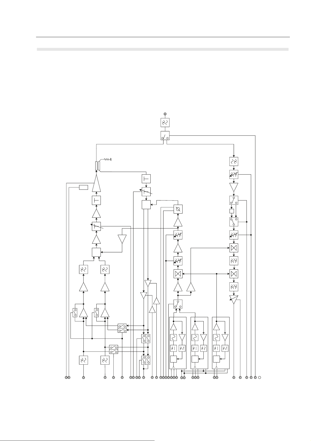
Figure 2. Radio Circuit Block Diagram
ANT
Temp
Q-
DEM
T
Q-
MOD
73.9MHz
450kHz
Tx 2nd. Local = 73.45MHz
Rx 2nd. Local = 73.45MHz
Tx 1st. Local 1 = 306.55 - 356.55MHz
Rx 1st. Local 1 = 306.10 - 356.10MHz
Tx 1st. Local 2 = 306.55 - 356.55MHz
Rx 1st. Local 2 = 306.10 - 356.10MHz
PLL
CNT
REF1
I_Lo
AT-LT
FB_IQ
TEMP
RAMPUD
Q_MOD
I_MOD
CONT_FD
AT-FB
LIN_ON
SEL_FB
CONT_FB
Q_Lo
I_RE F
Q_RE F
VCO1/2
VCO1_ON
STB_PLL1
BPF_SHIFT
PLL1_UNLOCK
PLL
CNT
PLL1
REF2
DT_COM
VCO2_ON
STB_PLL2
CLK_COM
PLL2_UNLOCK
PLL
CNT
PLL2
PLL3
13.0
MHz
STB_PLL3
PLL3_UNLOCK
Rx_2ndIF_OUT
ANT_SW
DEM_AGC
BPF_SHIFT
Rx_ATT_ON
ALT_RE F1_ON
16 CM5000 Mobile Repeater/Gateway - Basic Service Manual OVERVIEW
Receiver RF Amplifier and Mixer
Received signal that is connected to the antenna connector (J201) is fed to the receiver circuit via
the Low Pass Filter (FL201) and antenna switch (CD204 and IC204).
The antenna switch is controlled by the transistor (TR201 and TR203).
Received signal from antenna switch is fed to the double tuned band pass filter and unwanted signal
is rejected at the filter. This filter is voltage controlled tunable filter.
The control voltage is fed to the filter via the buffer amplifier (IC471).
Output signal from the filter is amplified by the RF amplifier (TR401) and fed to the attenuator circuit
(IC402 ad IC403). This attenuator is used to expand the dynamic range of the receiver and it is
switched according to received signal strength. Attenuator control signal is fed to the attenuator via
the transistor (TR470) and IC (IC472).
Output signal from the attenuator is filtered by the 2nd double tune band pass filter and fed to the 1st
mixer (TR402). This band pass filter is also tuned by the control voltage.
The 1st mixer is N-channel dual gate MOS FET. The received signal is fed to the Gate 1 and the
local signal is fed to the Gate 2 of the FET.
The received signal is converted to the 1st IF signal. The converted 1st IF signal is 73.9 MHz and it
is fed to the 1st IF circuit.
Receive
signal
First IF stage
The 1st IF stage consists of the crystal filter (FL470). The output signal from the 1st mixer id fed to
the input of the crystal filter (FL470), and unwanted signal is filtered. The output signal of the filter is
fed to the 2nd IF stage.
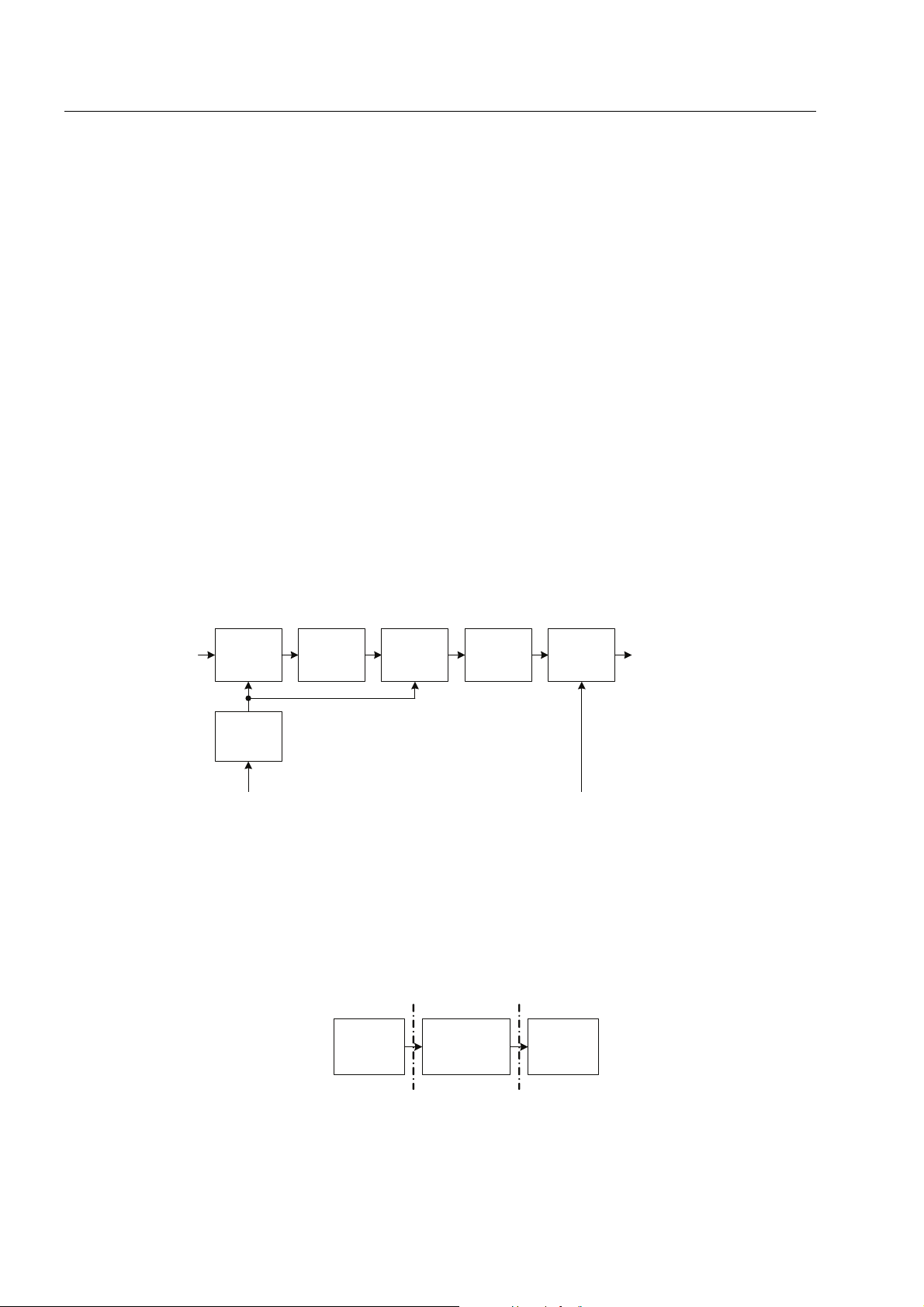
Figure 3. Receiver RF amplifier and Mixer Block Diagram
BPF BPF BPF BPF BPF
Buffer
Amp
BPF control signal 1st Local input
Figure 4. 1st IF Stage Block Diagram
1st
Mixer
1st X’ tal
Filter
2nd
Mixer
2nd Mixer
Receive RF
amplifier
and Mixer
1st IF stage 2nd IF stage
OVERVIEW CM5000 Mobile Repeater/Gateway - Basic Service Manual 17
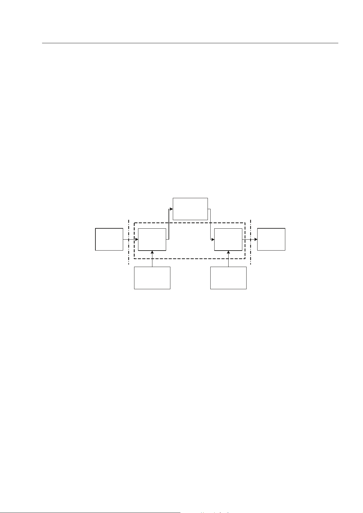
Second IF stage
The second IF stage consists of IF IC (IC470) and Ceramic filter (FL471). The IF IC consists of 2nd
Mixer and AGC amplifier.
The IF IC is consists of the 2nd Mixer and AGC amplifier.
Received signal from the 1st IF filter and 2nd local signal from the PLL are fed to the input terminal
of the 2nd mixer in the IF IC. Then 1st IF signal is converted to the 450 kHz 2nd IF signal. The signal
from the 2nd Mixer is connected to the AGC amplifier in the IF IC through 450 kHz ceramic filter.
Amplified signal at the AGC amplifier is fed to the ADC in the control circuit.
The AGC amplifier is controlled by the AGC voltage to maintain constant output voltage so as to
maintain appropriate ADC input voltage.
Control circuit determines the gain of AGC amplifier, and it generates the DC voltage by DAC and
fed to the AGC amplifier via the buffer amplifier (IC471).
Figure 5. 2nd IF stage and AGC amplifier Block Diagram
From 1st
IF
2nd
Mix
2nd Local
Signal
Ceramic
Filter
1st IF stage
PLL (Phase lock loop) frequency synthesizer
PLL (Phase lock loop) frequency synthesizer consists of two main blocks. One is RX 1st Local PLL
frequency synthesizer block and the other one is 2nd Local PLL frequency synthesizer.
1st Local PLL
The 1st Local PLL is consists of the PLL IC (IC501), Loop filter, VCO (HC501) and peripheral circuit.
To realise the TETRA TDMA burst signaling at high speed, fractional N counter type synthesizer is
used.
AGC
Amp
AGC control
signal
ADC
The 1st local signal is fed to the 1st mixer (TR402) in the receiver circuit and transmit mixer
(CD1002).
2nd Local PLL
The 2nd local PLL consists of the PLL IC (IC1001), Loop filter, VCO (TR1001), buffer transistor
(TR1003 and TR1004) and peripheral circuit.
Output signal of the VCO (TR1001) is amplified by the amplifier (TR1003 and TR1004). This signal
is divided into 2, one is feed back to the PLL IC. The other signal is fed to the receive mixer and the
transmit mixer through the buffer amplifier (TR1004).

18 CM5000 Mobile Repeater/Gateway - Basic Service Manual OVERVIEW
This PLL generates constant frequency in RX and TX.
Output signal of the 2nd PLL is fed to the 2nd mixer in the IF IC (IC470) and transmit mixer
(CD1002).
Transmit Mixer and Peripheral Circuit
The 1st local signal is amplified by the buffer amplifier (IC507 and TR1005) and fed to the transmit
mixer (CD1002).
The transmit mixer (CD1002) mixes the 1st local signal and 2nd local signal to generate the transmit
signal. High linearity double balanced mixer is used.
Mixed signal is fed to the 2 stages of the band pass filter and buffer amplifier.
The output of the mixer is filtered by the 1st band pass filter. Center frequency of the filter is controlled by the tuning voltage from the control circuit. The control voltage is generated by the DAC
(IC701) and fed to the filter via buffer amplifier (IC1002).
The output of the band pass filter is amplified by the buffer amplifier (IC2001) and fed to the 2nd
band pass filter. The 2nd band pass filter is also tunable filter same as 1st filter.
The output signal of the 2nd band pass filter is divided into 2, and fed to the quadrature modulator
and quadrature demodulator in the Cartesian Loop through the buffer amplifier (IC510 and IC511).
Figure 6. PLL (Phase lock loop) frequency synthesizer
PLL
CNT
REF1
PLL1
REF2
PLL2
13.0
MHz
PLL3
PLL
CNT
PLL
CNT
Rx 1st. Local ① = 306.10 -3 56.10MHz
Tx 1st. Local ① = 306.55 - 356.55MHz
Rx 1st. Local ② = 306.10 -3 56.10MHz
Tx 1st. Local ② = 306.55 - 356.55MHz
Rx 2nd. Local = 73.45MHz
Tx 2nd. Local = 73.45MHz
Transmitter I/Q modulator and buffer circuit
The base band signal of the digital signal processing circuit is fed to the quadrature modulator
(IC306) via OP amplifier (IC301), comparator (IC302) and buffer amplifier (IC305). The carrier signal
from PLL synthesizer is fed to the quadrature modulator.
To RX 1st Mix.
To Q- Mod.
To Q- Dem.
To RX 2nd
Mix.
The comparator in the modulation circuit operates as linearizer. Error correct signal of I and Q signals are generated at the linearizer circuit and fed to the comparator.
Carrier signal is modulated as pi/4 shift DQPSK signal by I and Q signal. Modulated signal is amplified by the buffer amplifier (TR301) to the appropriate level to drive the power amplifier.
Output of the buffer amplifier is fed to variable attenuator (CD301). Variable attenuator is controlled
by the digital signal processing circuit to output suitable level.

OVERVIEW CM5000 Mobile Repeater/Gateway - Basic Service Manual 19
The output of the attenuator is fed to the Power amplifier module (HC201).
Figure 7. Transmitter I/Q modulator and buffer Block Diagram
Carrier signal from PLL
synthesizer
I-Mod
signal
COM
LPF
Q-Mod
signal
From Cartesian Loop
Linearizer control signal
Transmitter Power Amplifier
Modulated signal is fed to the PA hybrid IC (HC201). This hybrid IC consists of 3 stage amplifier.
Using high level FET at the final stage to realize high linearity.
The gate bias voltage for the PA module is controlled by the control circuit and fed to the PA stage
via buffer amplifier (IC202).
The output of the PA is picked up by the directional coupler (CD202) and fed to the linearizer.
PIN diode antenna switch (CD203 and CD 204) are used to realize TDMA fast transmit receive
switching. The control circuit controls the bias current of the antenna switch with transistor (TR201).
The transmit signal that passed the antenna switch is fed to the Low pass filter (FL201) to reject the
spurious signal. Output signal of the LPF is fed to the BNC connector (J201).
Q-Mod.
LPFCOM
Buffer
Amp
Variable
Attenuator
To PA
Modulated
carrier
PA ON/OFF
control
Figure 8. Transmitter Power Amplifier Block Diagram
13.2 V
PIN
Diode
SW
LPF
PA
Directional
coupler
DC SW
To Linearizer
To receiver
To Antenna

20 CM5000 Mobile Repeater/Gateway - Basic Service Manual OVERVIEW
Linearizer and Power Control Circuit
This circuit consists of coupler, carrier phase shifter, quadrate demodulator, DC offset buffer and
comparator. To meet TETRA ACP specification requirements, Cartesian loop type linearizer is used.
The transmit signal that is picked up by the coupler is attenuated by the variable attenuator (CD303)
and fed to the quadrature demodulator (IC308). The output of the quadrate demodulator is fed to the
ADC of the control circuit and comparator. The control circuit calculates the phase and amplitude difference between the modulate signal and demodulate signal. Amplitude balance is adjusted at the
factory.
Phase difference is adjusted dynamically by phase shifter (IC319) to adjust the phase of quadrate
demodulator.
The DAC (IC702) output voltage is controlled and this voltage controls phase of the carried via buffer
amplifier (IC318).
The DC offset of the demodulated I and Q signal is corrected by adding the DC voltage from DAC
(IC702) at adder IC (IC318). Each I and Q signal is fed to the comparator and compared with reference modulation signal.
Transmit signal level is controlled by operating the forward attenuator (CD301) and reverse attenuator (CD303) complementary.
Those attenuator should be controlled depend on the transmit power level. Output voltage of the
DAC (IC702) is changed and this voltage is fed to the buffer amplifier (IC307) and attenuator
(CD301). Then the output level of attenuator (CD301) is changed and input level of the Power amplifier is changed.
Due to transmit level change, the picked up signal by the coupler for quadrature demodulator is
changed. To maintain the input level of the demodulator, attenuation of the reverse attenuator
(CD303) should be change. DAC (IC702) generates the control voltage for the reverse attenuator to
maintain the input level of the quadrature demodulator.
Power Supply
The voltage regulator of the RF circuit is series drop type. DC power via the power switch is fed to
the 9 V regulator IC (IC206). This voltage is used for transmit circuit.
9 V power is fed to the 5 V and 3.3 V regulator.
5 V voltage regulator (IC207) provides 5 V power for PLL circuit. Also this voltage is switched by
transistor (TR204) and fed to PLL circuit.
3.3 V voltage regulator (IC210) provides 3.3 V power for PLL circuit.
5 V regulator (IC208) provides 5 V power for the transmitter and receiver circuit. Also this voltage is
switched by transistor (TR206) and fed to receiver circuit.
5 V regulator (IC209) provides 5 V power for the transmitter circuit. Also this voltage is switched by
transistor (TR208) and fed to transmitter circuit.

OVERVIEW CM5000 Mobile Repeater/Gateway - Basic Service Manual 21
Figure 9. Linearizer and Power Control Block Diagram
BPF_SHIFT
CONT_FB
Q_REF
I_REF
Q_Lo
I_Lo
SEL_FB
AT-FB
FB_IQ
AT-LT
CONT_FD
LIN_ON
I_MOD
Q_MOD
RAMPUD
TEMP
From PLL synthesizer
MOD
Q-
DEM
Q-
Temp

22 CM5000 Mobile Repeater/Gateway - Basic Service Manual OVERVIEW
Key and display Unit
Panel CPU and Peripheral Circuit
Panel CPU (IC001) is communicating with Main CPU in the main unit. It transfer key operation to the
Main CPU and control the LCD based on the command from Main CPU.
CPU contains FLSH ROM, SD RAM interface, ADC, DAC, LCD controller and serial communication.
The Flash ROM (IC003) stores the source code, font data and portrayal bit map data. SDRAM
(IC002) is working area.
The panel CPU communicates with the main unit CPU via buffer IC (IC008). The serial communication is baud rate 115.2kbps, 8 bits, non parity and 0 V / 3.3 V level.
Temperature sensor IC (IC004) is used for the temperature compensation of the LCD contrast. The
CPU reads the temperature data of temperature sensor by ADC.
White color LED driver IC (IC106) controls the intensity of the LCD back light LED.
The intensity is controlled by the output voltage of the DAC in the CPU.
Interface
Key
Switch
CPU oscillates clock frequency with crystal (X001) and multiplies 8 times internally.
The core of the CPU operates at 115.2 MHz, Bus clock operates at 57.6 MHz and peripheral block
operate at 28.8 MHz.
The Connector (J006) connects the Key/Display unit and main unit.
Microphone signal, received signal for handset, hook signal, control signal and power source of
key/display unit are connected to the J006.
Key is switched ON and OFF by metal dome contacts (SW101 to SW124).
SW101 to SW114 and SW116 to SW124 are scanned by key matrix. The emergency key SW115 is
independent input contact.
Keys are back lighted by the blue LEDs. The back light intensity is controlled as 3 levels (OFF - Low
- High) by controlling the transistor (TR107 and TR108) by the control signal of the CPU.
The power switch and volume control are adjusted by the rotary knob (SW001).
Pushing the rotary knob turns the radio on. Turning the encoder controls the audio volume and
selects the screen menu.
Other than pushing the rotary knob, pressing the emergency button will turn the radio on. In this
case an emergency call will be originated as soon as power on the radio.

OVERVIEW CM5000 Mobile Repeater/Gateway - Basic Service Manual 23
Display
The display is 2.8 inch STN type 240RGB x 160 dots matrix color LCD module (DD001).
The control signal from the Panel CPU is connected to the LCD unit via the LCD interface connector
(J102).
The LCD is back lighted by the internal back light white LED in the LCD module. Intensity of the LCD
back light is controlled by the output voltage of the back light power supply (IC106) by the output
voltage of the DAC of the CPU.
Back light signal is connected to the LCD unit via the back light connector (J101).
Indicator LED
2 colors LED indicator (CD102) indicates the status of the radio. The panel CPU controls the LED as
red, green or amber via the transistor (TR101 and TR102)
Connector
Microphone is connected to the Key/Display unit via the RJ-45 type connector (J005).
Microphone signal, hook signal, receive signal and function key signal for handset are connected to
the microphone connector.
Audio Circuit
The microphone signal fed to the connector (J005) is amplified by the microphone amplifier (IC107)
and fed to the main unit via interface connector (J006).
Receive signal for the handset is amplified by the audio amplifier (IC107) and fed to the microphone
connector.
Power Supply Circuit
The power supply for the Key/Display unit converts the DC 9 V from the main unit to generates each
voltage power for the Key/Display unit.
The 9 V voltage is fed to the audio circuit, indicator LED and back light LED.
The 5 V voltage is generated by the voltage regulator IC (IC102) and fed to the back light of the LCD.
The 3.3 V voltage is generated by the voltage regulator IC (IC103) and fed to the CPU, LCD module
and other digital circuit.
The 1.5 V voltage is generated by the voltage regulator IC (IC105) and fed to the CPU core.
1.5 V power will be turn on after turn ON the 3.3 V regulator.
The reset IC (IC108) generates the reset signal at power on the radio and reset the CPU.

24 CM5000 Mobile Repeater/Gateway - Basic Service Manual OVERVIEW
driver
Figure 10. Key/display Sub-Unit block Diagram
LCD
LED
Key
Matrix
Rotary
knob
LCD
I/F
LED
driver
Temp.
LED
driver
Mic
Con.
D/A
LCD
controller
PWM
A/D
Panel CPU
Amp
SD
RAM
FLASH
ROM
Serial
line
Mic Audio
Rec. Audio
To Control circuit
To Control circuit
TEST SETUP & ADJUSTMENT CM5000 Mobile Repeater/Gateway - Basic Service Manual 25
CHAPTER 4
TEST SETUP & ADJUSTMENT
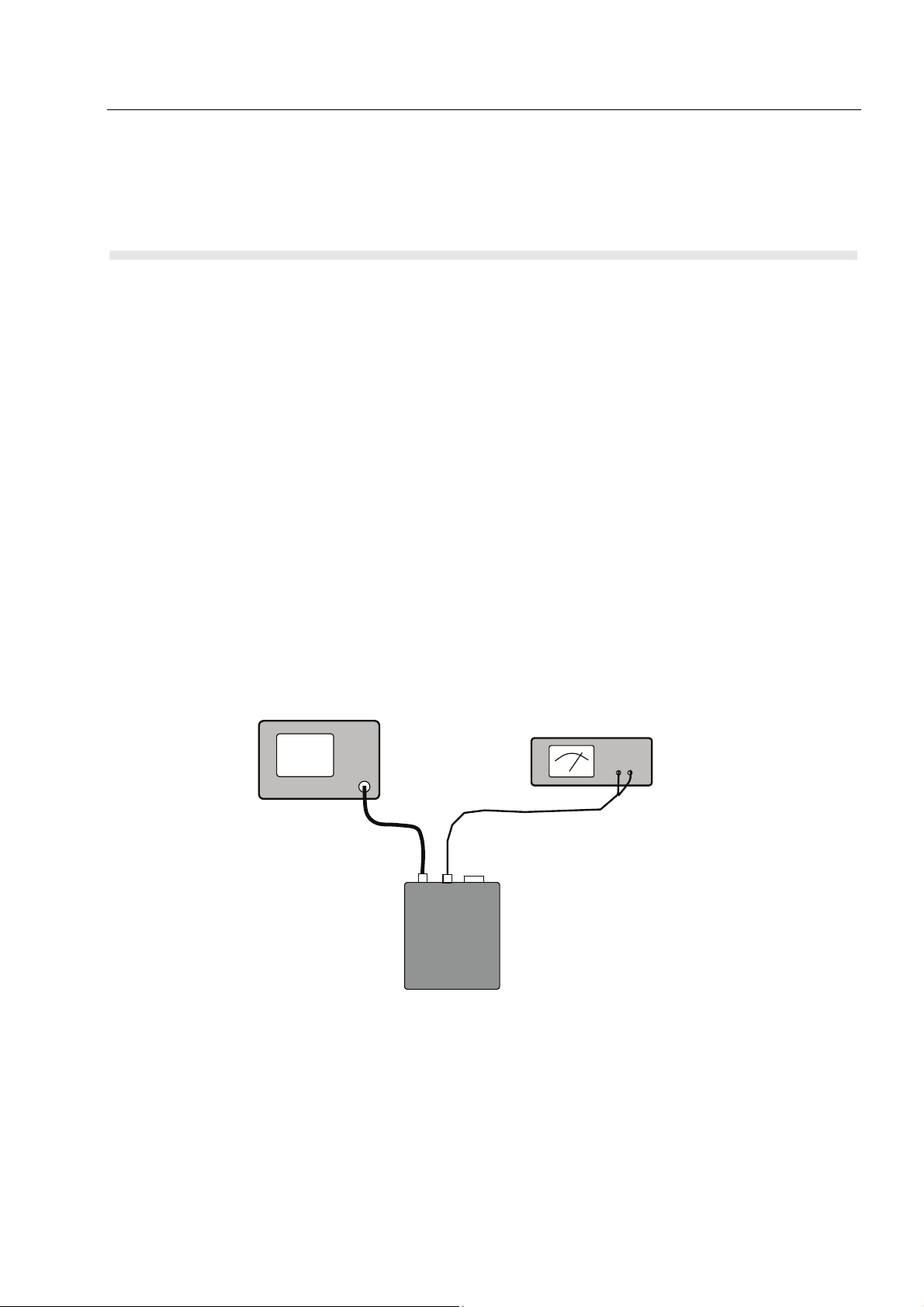
Typical Te st Se tu p
STEP 1
Set the DC power supply to 13.2 V. (More than 5 A current capacity DC power supply is required.)
STEP 2
Connect under adjustment radio terminal to DC power supply. (The radio terminal should be turned
off in this period.)
STEP 3
Connect the Antenna connector of radio terminal and RF connector of TETRA Tester of AEROFLEX
Type 2968.
STEP 4
Press Menu key and numeric key [2] and the Rotary knob simultaneously. The radio terminal
switches to JRC TEST mode.
Figure 11. Test Connection Diagram
AEROFLEX TETRA
Tester
Model 2968
RF Cable
DC Power supply
More than 5A current capacity
13.2 V
Radio Unit

26 CM5000 Mobile Repeater/Gateway - Basic Service Manual TEST SETUP & ADJUSTMENT
Self Check
When a radio unit is turned on, a self check program is started automatically.
If no failures occur then all segments of the display on the front panel are turned on. A short beep
indicates that the self check test has been completed without a failure.
Self check takes approximately 1 second.
After the test radio unit displays its own ID for approximately 1 second and switches to normal operation.
Error Codes
If the radio unit fails in the self check routine, an error code is shown on the display and a alert beep
is played.
Table 2. Error codes
Error Code Description
Native data prog. error Programming data error
Radio config. prog. error Radio configuration programming error
Security prog. error Security data programming error

TEST SETUP & ADJUSTMENT CM5000 Mobile Repeater/Gateway - Basic Service Manual 27
IFR 2968 - Channel and Mode Setting
Figure 12. Panel Layouts
IFR 2968 should be set as follows:
Table 3. Channel and mode
Radio
Channel
IFR2968
Channel
Menu
Rotary
knob
S1
Left
Enter
Frequency
IFR2968
Setting
TX RX Band
S2
EMG
Up
(see item
2 and 3)
Normal/
Reverse
Power
adjustment
3200 3200 380.0125 MHz A Reverse
3600 3600 380.0125 MHz A Normal x
4000 4000 390.0125 MHz x
4400 400.0125 MHz B Normal x
4208 0208h 405.2125 MHz B Normal
4608 0608h 405.2125 MHz B Normal
4800 800 410.0125 MHz B Normal x
5200 1200 420.0125 MHz B Normal x
5600 1600 430.0125 MHz x
5200 1200h 430.0125 MHz Normal
4800 0800h 430.0125 MHz Reverse
Note: On the radio the channels have a displacement of 4000 (B Band only). For example IFR
Channel 0800 is equal to CM5000 Channel 4800.

28 CM5000 Mobile Repeater/Gateway - Basic Service Manual TEST SETUP & ADJUSTMENT
STEP 1
Set the IFR to the following parameter in system parameters.
(MAX TX LEVEL) to 40 dBm
STEP 2
RF Gen Level
-112 dBm
STEP 3
Channel Plan
Set to "USER DEFINED"
STEP 4
Channel Block setting in "User Defined" menu
i) Select "CHANNEL BLOCK 1" and enter the following parameters:
CHANNEL BLOCK EXCLUDED
LOWEST CHANNEL 0000
HIGHEST CHANNEL 4095
LOWEST CHANNEL TX FREQUENCY 290.0125 MHz
DUPLEXT OFFSET 10 MHz
CHANNEL SPACING 25 kHz
ii) Select "CHANNEL BLOCK 2" and enter the following parameters:
CHANNEL BLOCK EXCLUDED
LOWEST CHANNEL 0000
HIGHEST CHANNEL 4095
LOWEST CHANNEL TX FREQUENCY 310.0125 MHz
DUPLEXT OFFSET -10 MHz
CHANNEL SPACING 25 kHz
iii) Select "CHANNEL BLOCK 2" and enter the following parameters:
CHANNEL BLOCK EXCLUDED
LOWEST CHANNEL 0000
HIGHEST CHANNEL 4095
LOWEST CHANNEL TX FREQUENCY 390.0125 MHz
DUPLEXT OFFSET 10 MHz
CHANNEL SPACING 25 kHz
iv) Select "CHANNEL BLOCK 2" and enter the following parameters:
CHANNEL BLOCK EXCLUDED
LOWEST CHANNEL 0000
HIGHEST CHANNEL 4095
LOWEST CHANNEL TX FREQUENCY 410.0125 MHz
DUPLEXT OFFSET -10 MHz
CHANNEL SPACING 25 kHz
For A Band (380 - 400 MHz)
A) Normal setting:
STEP 4
i) Press the (USER DEFINED KEY) and set the following parameters:
FREQ BAND 3
OFFSET 3
DUPLEX SPACING 0
REVERSE 0

TEST SETUP & ADJUSTMENT CM5000 Mobile Repeater/Gateway - Basic Service Manual 29
ii) Select "CHANNEL BLOCK 1" and set the following parameter:
CHANNEL BLOCK INCLUDED
Other Channel Blocks (Channel Block 2, 3, 4) set to "EXCLUDED"
B) Reverse setting:
STEP 4
i) Press the (USER DEFINED KEY) and set the following parameters:
FREQ BAND 3
OFFSET 3
DUPLEX SPACING 0
REVERSE 1
ii) Select "CHANNEL BLOCK 2" and set the following parameter:
CHANNEL BLOCK INCLUDED
Other Channel Blocks (Channel Block 1, 3, 4) set to "EXCLUDED"
For B Band (400 - 430 MHz)
A) Normal setting:
STEP 4
i) Press the (USER DEFINED KEY) and set the following parameters:
FREQ BAND 4
OFFSET 3
DUPLEX SPACING 0
REVERSE 0
ii) Select "CHANNEL BLOCK 3" and set the following parameter:
CHANNEL BLOCK INCLUDED
Other Channel Blocks (Channel Block 1, 2, 4) set to "EXCLUDED"
B) Reverse setting:
STEP 4
i) Press the (USER DEFINED KEY) and set the following parameters:
FREQ BAND 4
OFFSET 3
DUPLEX SPACING 0
REVERSE 1
ii) Select "CHANNEL BLOCK 4" and set the following parameter:
CHANNEL BLOCK INCLUDED
Other Channel Blocks (Channel Block 1, 2, 3) set to "EXCLUDED"

30 CM5000 Mobile Repeater/Gateway - Basic Service Manual TEST SETUP & ADJUSTMENT
RX VCO frequency adjustment
Preparation
Press Menu key, numeric key [2] and the Rotary knob simultaneously.
The radio terminal enters T1 TEST mode.
1st Local VCO
Note: The VCO used in the CM5000 has no tunable device. No adjustment is required for the VCO.
This section describes verification method.
STEP 1
Set the radio to channel 3200 using numeric keys and confirm.
STEP 2
Check the voltage of test point TP640. The normal voltage is higher than 2 V.
If the voltage is out of the above range, it means the VCO is unlocked.
2nd Local VCO adjustment
Note: The VCO used in the CM5000 has no tunable device. No adjustment is required for the VCO.
This section describes verification method.
STEP 1
Set the radio to channel 3200 using numeric keys and confirm.
STEP 2
Check the Voltage of test point TP644, using high impedance Digital Volt Meter.
The normal voltage of the test point TP644 is higher than 2 V.
If the voltage is out of the above range, it means the VCO is unlocked.
Confirming receiver sensitivity
Note: The Loop Back Test Mode is using on this adjustment procedure. Accordingly transmitter
function should work to execute this test mode.
Preparation
Preparation of AEROFLEX Tester 2968
STEP 1
Set the AEROFLEX Tester to T1 LOOP BACK MODE as follows:
T1 Loop Back ON
Burst Mode Normal
Signal format TCH/7.2
RF Level -110 dBm

TEST SETUP & ADJUSTMENT CM5000 Mobile Repeater/Gateway - Basic Service Manual 31
STEP 2
Set the AEROFLEX tester channel to 3200.
STEP 3
Press Menu key, numeric key [2] and the Rotary knob simultaneously. The radio terminal enters T1
TEST mode.
STEP 4
Set the tested radio terminal to channel 3200.
STEP 5
Press [*] key for 12.5 kHz offset. CM5000 displays ‘+’ on right side of channel number.
Confirm sensitivity
Note: No manual tunable device in the RF band pass filter. No adjustment is required for receiver.
STEP 1
Confirm that tester BER indication is less than 1%.
Transmit Power Adjustment
The transmit power setting is required after repair of transmitter circuit.
Preparation
STEP 1
Test connection diagram is shown in figure 11.
STEP 2
Press Menu key, numeric key [9] and the Rotary knob simultaneously.
STEP 3
While the bar graph is shown on the display, press the [EMG] and [Left] key simultaneously.
The radio terminal enters RX ADJUST MODE.
STEP 4
Press and hold the Menu key for 5 seconds disregarding the error tone.
STEP 5
Set the radio to channel 3600 using numeric keys.
STEP 6
Confirm the frequency as 390.0125 MHz.
STEP 7
Press the key [BST] on the Control head.
The radio terminal enters TX ADJUST MODE.

32 CM5000 Mobile Repeater/Gateway - Basic Service Manual TEST SETUP & ADJUSTMENT
Adjustment
Adjustment for channel 3600
Setting the channel
STEP 1
Set the radio to channel 3600 using numeric keys.
STEP 2
Set IFR2968 to A Band Normal setting.
Power adjustment on the channel
STEP 1
Press the key [BST] on the Control head.
The the radio terminal switches to TX ADJUST MODE.
STEP 2
Confirm the “CH3600 380.0125 MHz” on the display.
STEP 3
Confirm the “POWER 37 dBm” on the display.
STEP 4
Confirm the “LT” is selected.
STEP 5
Adjust the output power to +37+/-0.5 dBm using the Rotary knob.
STEP 6
Press the [Right] navigation key for course adjustment.
STEP 7
Press the [Up] navigation key to select “FB”.
STEP 8
Adjust the output power to +37+/-0.5 dBm using the Rotary knob.
STEP 9
Press the [Right] navigation key for course adjustment.
STEP 10
Press the [Left] navigation key and confirm “POWER 35 dBm“ on the display.
STEP 11
Confirm the “LT” is selected.
STEP 12
Adjust the output power to +35+/-0.5 dBm using Rotary encoder
STEP 13
Press the [Right] navigation key for course adjustment.
STEP 14
Press the [Up] navigation key to select “FB”.
STEP 15
Adjust the output power to +35+/-0.5 dBm using the Rotary knob.

TEST SETUP & ADJUSTMENT CM5000 Mobile Repeater/Gateway - Basic Service Manual 33
STEP 16
Press the [Right] navigation key for course adjustment.
STEP 17
Press the [Left] navigation key and confirm “POWER 30 dBm“ on the display.
STEP 18
Confirm the “LT” is selected.
STEP 19
Adjust the output power to +30+/-0.5 dBm using the Rotary knob.
STEP 20
Press the [Right] navigation key for course adjustment.
STEP 21
Press the [Up] navigation key to select “FB”.
STEP 22
Adjust the output power to +30+/-0.5 dBm using the Rotary knob.
STEP 23
Press the [Right] navigation key for course adjustment.
STEP 24
Press the [Left] navigation key and confirm “POWER 25 dBm“ on the display.
STEP 25
Confirm the “LT” is selected.
STEP 26
Adjust the output power to +25+/-0.5 dBm using the Rotary knob.
STEP 27
Press the [Right] navigation key for course adjustment.
STEP 28
Press the [Up] navigation key to select “FB”.
STEP 29
Adjust the output power to +25+/-0.5 dBm using the Rotary knob.
STEP 30
Press the [Right] navigation key for course adjustment.
STEP 31
Press the [Left] navigation key and confirm “POWER 20 dBm“.on the display.
STEP 32
Confirm the “LT” is selected.
STEP 33
Adjust the output power to +20+/-0.5 dBm using the Rotary knob.
STEP 34
Press the [Right] navigation key for course adjustment.
STEP 35
Press the [Up] navigation key to select “FB”.

34 CM5000 Mobile Repeater/Gateway - Basic Service Manual TEST SETUP & ADJUSTMENT
STEP 36
Adjust the output power to +20+/-0.5 dBm using the Rotary knob.
STEP 37
Press the [Right] navigation key for course adjustment.
STEP 38
Press the [Left] navigation key and confirm “POWER 15 dBm“ on the display.
STEP 39
Confirm the “LT” is selected.
STEP 40
Adjust the output power to +15+/-0.5 dBm using the Rotary knob.
STEP 41
Press [Right] key for course adjustment.
STEP 42
Press the [Up] navigation key to select “FB”. “FB” should be highlighted by black background.
STEP 43
Adjust the output power to +15+/-0.5 dBm using the Rotary knob.
STEP 44
Press the [Right] navigation key for course adjustment.
STEP 45
After finishing the power adjustment, press and hold the Enter key for 1 second.
The “MEMORY” message appears on the display and audible tone is played.
STEP 46
Press [RX] to terminate transmitting.
Adjustment for channel 4000
Setting the channel
STEP 1
Set the radio to channel 4000 using numeric keys.
STEP 2
Set IFR2968 to A Band Normal setting.
Power adjustment on the channel
See power adjustment for channel 3600.
Adjustment for channel 4400
Setting the channel
STEP 1
Set the radio to channel 4400 (IFR 0400) using numeric keys.
STEP 2
Set IFR2968 to B Band Normal setting.

TEST SETUP & ADJUSTMENT CM5000 Mobile Repeater/Gateway - Basic Service Manual 35
Power adjustment on the channel
See power adjustment for channel 3600.
Adjustment for channel 4800
Setting the channel
STEP 1
Set the radio to channel 4800 (IFR 0800) using numeric keys.
STEP 2
Set IFR2968 to B Band Normal setting.
Power adjustment on the channel
See power adjustment for channel 3600.
Adjustment for channel 5200
Setting the channel
STEP 1
Set the radio to channel 5200 (IFR 1200) using numeric keys.
STEP 2
Set IFR2968 to B Band Normal setting.
Power adjustment on the channel
See power adjustment for channel 3600.
Adjustment for channel 5600
Setting the channel
STEP 1
Set the radio to channel 5600 (IFR 1600) using numeric keys.
STEP 2
Set IFR2968 to B Band Normal setting.
Power adjustment on the channel
See power adjustment for channel 3600.
Store the power adjustment
To store the power adjustments, turn off the radio by pressing the [PWR] key.

36 CM5000 Mobile Repeater/Gateway - Basic Service Manual TEST SETUP & ADJUSTMENT
Receiver Adjustment
The RSSI setting is required after the repair of receiver circuit.
Preparation
STEP 1
Set the IFR2968 to B band Normal setting.
STEP 2
Set the IFR2968 as follows:
Channel 0200
RF level -70 dBm
STEP 3
Press Menu key, numeric key [9] and the Rotary knob simultaneously.
STEP 4
While the bar graph is shown on the display, press the [EMG] and [Left] keys simultaneously.
Then the radio terminal goes into RX ADJUST MODE.
STEP 5
Press and hold the Menu key for 5 seconds disregarding the error tone.
STEP 6
Set the radio to channel 4200 using numeric keys.
STEP 7
Confirm the frequency as 405.0125 MHz.
Adjustment
STEP 1
Confirm the “STAGE LEVEL HI 1” on the display and wait 10 seconds.
STEP 2
Press and hold the Enter key for 1 second.
The “MEMORY” message appears on the display and audible tone is played.
STEP 3
Press the [Up] navigation key and confirm the “STAGE LEVEL HI 2” on the display.
STEP 4
Wait 5 seconds. Then press and hold the Enter key for 1 second.
Then “MEMORY” message appears on the display and audible tone is playes.
STEP 5
Set the IFR2968 as follows:
RF level -90 dBm
STEP 6
Press the [Up] navigation key and confirm the “STAGE LEVEL LOW” on the display.

TEST SETUP & ADJUSTMENT CM5000 Mobile Repeater/Gateway - Basic Service Manual 37
STEP 7
Wait 5 seconds. Then press and hold the Enter key for 1 second.
The “MEMORY” message appears on the display and audible tone is played.
STEP 8
Press the [Up] navigation key and confirm the “RSSI CHECK” on the display.
STEP 9
Confirm the RSSI is within the –90 +/- 2 dBm.
STEP 10
Change IFR2968 RF level to -70 dBm.
STEP 11
Confirm the RSSI is within the –70 +/- 2 dBm.
STEP 12
Turn off the radio by pressing the Rotary knob key

38 CM5000 Mobile Repeater/Gateway - Basic Service Manual
THIS PAGE INTENTIONALLY LEFT BLANK

CONNECTOR PIN FUNCTION CM5000 Mobile Repeater/Gateway - Basic Service Manual 39
CHAPTER 5
CONNECTOR PIN FUNCTION
Connectors
This section presents the following connectors and their pin functions:
• Microphone connector
• Accessory connectors
• Antenna connector
• GPS antenna connector
• Power connector

40 CM5000 Mobile Repeater/Gateway - Basic Service Manual CONNECTOR PIN FUNCTION
Microphone Connector (Panel)
This connector provides the communication with Fist Microphone, Handset and Desk Microphone
using 10-pin RJ type connector.
Table 4. Microphone connector pins
No. Function Description
1 No connection
2 No connection
3 Hook switch input Microphone off-hook signal (Active Low)
4 Ground Ground
5 Microphone input Microphone audio input
(-43 dBm@600 ohm with 9 V phantom powered circuit)
6 PTT switch input PTT switch signal (Active Low)
7 No connect
8 Handset audio output Handset audio (no volume control)
9 Analogue 1 Analogue input to A/D converter (for handset)
10 Analogue 2 Analogue input to A/D converter (for handset)
CONNECTOR PIN FUNCTION CM5000 Mobile Repeater/Gateway - Basic Service Manual 41
Accessory Connector 1
This connector provides communication with External Speaker, External Microphone, External PTT
Switch, External Emergency Switch, Ignition Sense Cable External Alarm Switch, Buzzer and RS232C interface using 20-pin type connector.
Table 5. Accessory connector 1 pins
No. Function Description
1 External Speaker- output Speaker output (BTL) with Pin 16
2 External Microphone input
3 External PTT switch input Microphone off-hook signal (Active Low)
4 External Alarm output Ground
5 TX Audio input Microphone audio input
(-43 dBm@600 ohm with 9 V phantom powered circuit)
6 Keyfail / Flash input PTT switch signal (Active Low)
7 Analogue Ground Ground for analogue input/output
8 Digital Ground Ground for digital input/output
9 Emergency switch input To enable Emergency transmission with the Radio
turned on (Active Low)
10 Ignition switch input To turn on the Radio with Ignition input (Active high)
11 RX Audio output Received RX signal output (no volume control)
775 mVRMS@600 ohm
12 Audio PA Enable input To on/off Speaker input (SP active when High or Open)
13 SWB+ Switched power supply (less than 1A)
14 Hook switch input Hook switch signal (High=Off hook, Low=On hook)
15 SCI DTR To communicate Personal Computer with 0 - 3.3 V inter-
face(DTR), Input to radio unit
16 External Speaker+ output Speaker output (BTL) with Pin 1
17 SCI CTS To communicate Personal Computer with 0 - 3.3 V interface
(CTS), Output from radio unit
18 SCI RTS To communicate Personal Computer with 0 - 3.3 V interface
(RTS), Input to radio unit
19 SCI RXD To communicate Personal Computer with 0 - 3.3 V interface
(RXD), Output from radio unit
20 SCI TXD To communicate Personal Computer with 0 - 3.3 V interface
(TXD), Input to radio unit

42 CM5000 Mobile Repeater/Gateway - Basic Service Manual CONNECTOR PIN FUNCTION
Accessory Connector 2
This connector provides the communication with RS-232C interface using 7-pin type connector.
Table 6. Accessory connector 2 pins
No. Function Description
1 GND Ground
2 No connection
3 CTS To communicate Personal Computer with standard RS-
232C interface (RTS), Input to radio unit
4 RTS To communicate Personal Computer with standard RS-
232C interface (CTS), Output from radio unit
5 SCI TXD To communicate Personal Computer with standard RS-
232C interface (RXD), Output from radio unit
6 SCI RXD To communicate Personal Computer with standard RS-
232C interface (TXD), Input from radio u
7 GND Ground
Antenna Connector
This connector will provide the connection with RF Antenna for 380 – 430 MHz band.
Table 7. Antenna connector
Item Specification
Type of connector BNC connector
Impedance 50 ohm

CONNECTOR PIN FUNCTION CM5000 Mobile Repeater/Gateway - Basic Service Manual 43
GPS Antenna Connector
This connector will provide the connection with GPS Antenna.
Table 8. GPS Antenna connector
Item Specification
Type of connector FME connector
Impedance 50 ohm
Power Supply for Antenna 5 VDC Max. 30 mA
Power Connector
This connector provides the connection to the car battery or the power supply via power cable.
Table 9. Power connector
Item Specification
Type of connector 2 pin special connector
Voltage 13.2 V

44 CM5000 Mobile Repeater/Gateway - Basic Service Manual
THIS PAGE INTENTIONALLY LEFT BLANK
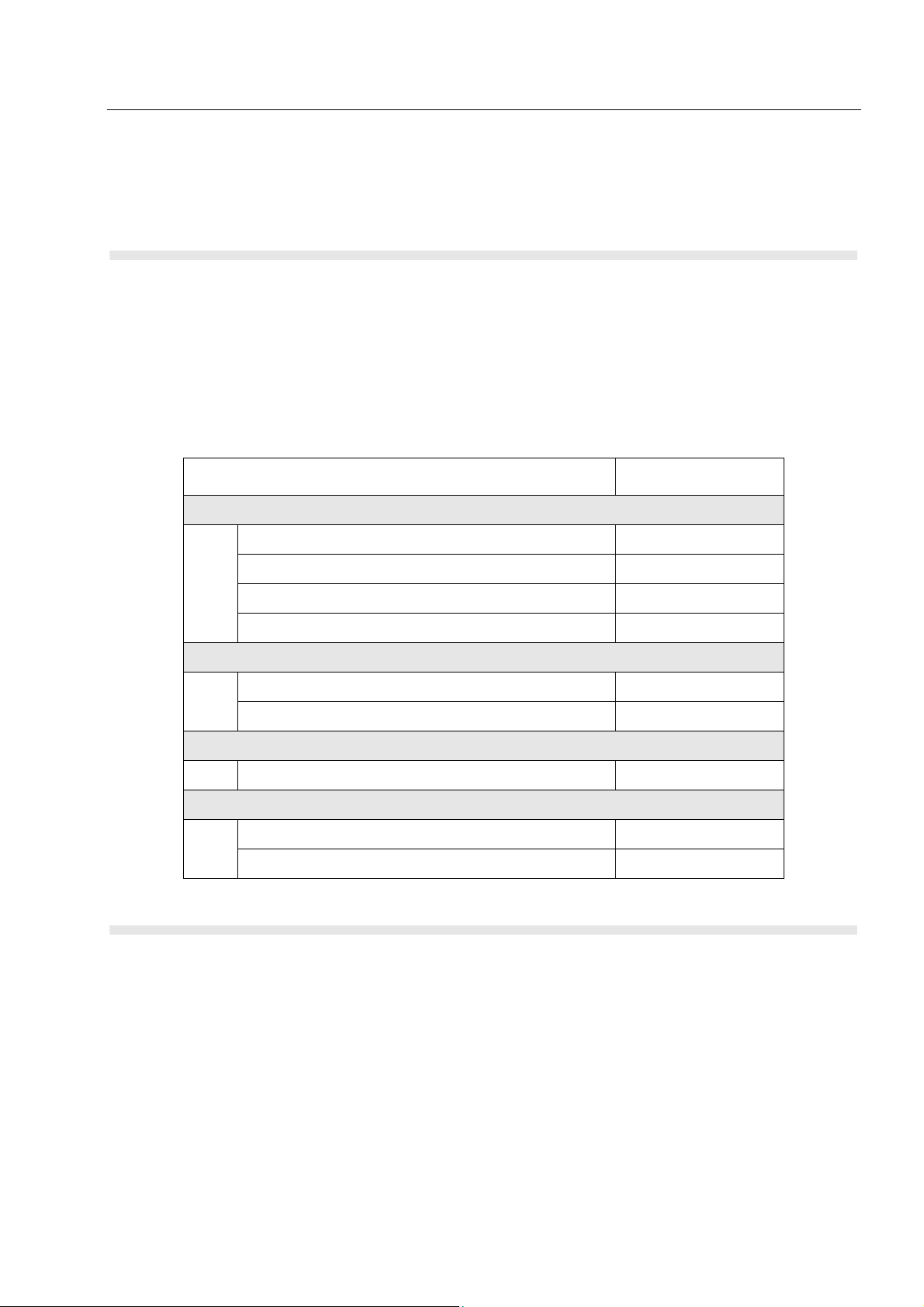
PARTS LISTS AND DRAWINGS CM5000 Mobile Repeater/Gateway - Basic Service Manual 45
CHAPTER 6
PARTS LISTS AND DRAWINGS
Replacement Parts List
Damaged parts should be replaced with identical replacement parts.
For complete information on ordering required parts and kits, contact your local customer service
representative.
Table 10. Spare parts
Item Part number
Control Head Housing
Control Head Front Housing Assembly WAWN4491A
Volume Knob Assembly
LCD
IF3G Cables
Diagrams
• Control Head Assembly
Control Head Rear Housing Assembly WAWN4492A
Control Head Shield Case WAWN4493A
Cleartone Control Head Board 8466593A01
Cleartone Volume Knob Assembly Cap 3866500A01
Cleartone Volume Knob 3666503A01
Cleartone CM5000 LCD module 7266502A01
Cleartone cable IF3G to CM5000 3066578B01
Cleartone cable IF3G to Control Head 3066579B01

46 CM5000 Mobile Repeater/Gateway - Basic Service Manual PARTS LISTS AND DRAWINGS
No. Description Part Number
1 Control Head Front Housing Assembly WAWN4491A
2 Control Head Rear Housing Assembly WAWN4492A
3 Control Head Shield Case WAWN4493A
4Cleartone Control Head Board 8466593A01
5Cleartone Volume Knob Assembly Cap 3866500A01
6Cleartone Volume Knob3666503A01
7Cleartone Volume Knob O-Ring P-6 0466504A01
8 Cleartone CM5000 LCD module 7266502A01
Mechanical Parts List
5
6
7
1
4
8
3
2

REPLACEMENT PARTS & KITS CM5000 Mobile Repeater/Gateway - Basic Service Manual 47
APPENDIX A
REPLACEMENT PARTS & KITS
Servicing CM5000 Mobile Units
Service for the mobile units is based on the substitution method; a faulty part is replaced by a working one, providing quicker service to the customer. For example, if the controller board is faulty, it is
replaced. If the mobile requires more complete testing or servicing than that is available at field level,
it is sent to the European Radio Service Centre; where it is serviced, and returned to the Regional
Service Centre.
Level 1 Maintenance
This manual covers Level 1 Maintenance: at Level 1 maintenance you replace the transceiver
and/or accessories and send the faulty transceiver and/or accessories to higher level of maintenance. For details, please refer to Technical Support and Further Assistance from Motorola.
The CM5000 mobiles are programmed at the factory. They cannot be tuned at the field service
level.
Level 2 and Level 3 Maintenance
The Level 2 and 3 maintenance can be only performed at the Motorola Service Center/Depot.
Contact your local Motorola G&PS for information.

48 CM5000 Mobile Repeater/Gateway - Basic Service Manual REPLACEMENT PARTS & KITS
Service Information
Europe, Middle East and Africa Region
European Radio Support Centre (ERSC)
Motorola European Radio Support Centre is available at:
Motorola European Radio Support Centre ERSC
Tel.: +49 (0)30 6686 1555
Fax: +49 (0)30 6686 1579
Am Borsigturm 130
13507 Berlin
Germany
EMEA Systems Support Centre (ESSC)
The Systems Support Centre is available at:
Telephone: +44 (0) 1256 484448
E-mail: ESSC@motorola.com
Piece Parts
Some replacement parts, spare parts, and/or product information can be ordered directly. If a complete Motorola part number is assigned to the part, it is available from Motorola Radio Aftermarket
and Accessory Division (AAD). If no part number is assigned, the part is not normally available from
Motorola. If a parts list is not included, this generally means that no user-serviceable parts are available for that kit or assembly.
Parts Identification and Ordering
Request for help in identification of non-referenced spare parts should be directed to the Customer
Care Organization of Motorola’s local area representation. Orders for replacement parts, kits and
assemblies should be placed directly on Motorola’s local distribution organization or via the Extranet
site Motorola Online at: https://emeaonline.motorola.com
EMEA Test Equipment Support
.
Information related to support and service of Motorola Test Equipment is available by calling the
Motorola Test Equipment Service in Germany at +49 (0) 6128 702179, Telefax +49 (0) 6128
951046, through the Customer Care Organization of Motorola’s local area representation, or via the
Internet at: http://www.gd-decisionsystems.com/cte/
.

REPLACEMENT PARTS & KITS CM5000 Mobile Repeater/Gateway - Basic Service Manual 49
Asia, Pacific Region
Technical Support
Technical support is available to assist the dealer/distributor in resolving any malfunction which may
be encountered. Initial contact should be by telephone wherever possible.
When contacting Motorola Technical Support, be prepared to provide the product model number
and the unit’s serial number.
Further Assistance from Motorola
You can also contact the Customer Help Desk through the following web address:
http://www.motorola.com/governmentandenterprise/contactus
Piece Parts
Some replacement parts, spare parts, and/or product information can be ordered directly. If a complete Motorola part number is assigned to the part, it is available from Motorola Radio Aftermarket
and Accessory Division (AAD). If no part number is assigned, the part is not normally available from
Motorola. If a parts list is not included, this generally means that no user-serviceable parts are available for that kit or assembly.
.
Note on this digital TETRA Terminal: The CPS has no capability to tune the terminal. Tuning the
terminal can only be performed at the factory or at the appropriate Motorola Repair Centre.
Component replacement can affect the terminal tuning and must only be performed by the
appropriate Motorola Repair Centre.
Request for help in identification of non-referenced spare parts should be directed to the Customer
Care Organization of Motorola’s local area representation. Orders for replacement parts, kits and
assemblies should be placed directly on Motorola’s local distribution organization or via Motorola
Online (Extranet).

50 CM5000 Mobile Repeater/Gateway - Basic Service Manual REPLACEMENT PARTS & KITS
Latin America Region
Latin America Radio Support Centres
The Customer Support is available through the following service centres:
Warranty and Repairs:
MOTOROLA DE COLOMBIA SERVICE CENTRE
Torre Banco Ganadero
Carrera 7 No. 71-52
Torre B piso 13
Oficina 1301
Bogota- Colombia
(571) 376-6990
MOTOROLA DE MEXICO SERVICE CENTRE
Bosques de Alisos #125
Col. Bosques de las Lomas
CP 05120 Mexico DF
5252576700
Piece Parts:
To order parts in Latin America and the Caribbean contact your local Motorola CGISS representative.
MOTOROLA, INC.
Latin American Countries Region
789 International Parkway
Sunrise, FL 33325
USA 954-723-8959
MOTOROLA DE ARGENTINA
Ave. del Libertador 1855
B1638BGE, Vicente Lopez
Buenos Aires, Argentina
5411-4317-5300
MOTOROLA DE LOS ANDES C.A.
Ave. Francisco de Miranda
Centro Lido, Torre A
Piso 15, El Rosal
Caracas, 1060 Venezuela
58212-901-4600
MOTOROLA DO BRASIL LTDA.
Av. Chedid Jafet
222 Bloco D Conjuntos 11,12,21,22 E 41
Condominio Millennium Office Park
04551-065- Vila Olimpia, Sao Paulo
Brasil
5511-3847-668
MOTOROLA CHILE
Ave. Nueva Tajamar 481

REPLACEMENT PARTS & KITS CM5000 Mobile Repeater/Gateway - Basic Service Manual 51
Edif. World Trade Center
Of. 1702, Torre Norte
Las Condes
Santiago, Chile
562-338-9000
MOTOROLA DE COLOMBIA, LTDA.
Carrera 7 #71-52
Torre A, Oficina 1301
Bogotá, Colombia
571-376-6990
MOTOROLA DE COSTA RICA
Parque Empresarial Plaza Roble
Edificio El Portico, 1er Piso
Centro de Negocios Internacional
Guachepelin, Escazu
San Jose, Costa Rica
506-201-1480
MOTOROLA DEL ECUADOR
Autopist Gral. Rumiñahui, Puente 2
Conjunto Puerta del Sol Este-Ciudad Jardin
Pasa E, Casa 65
Quito, Ecuador
5932-264-1627
MOTOROLA DE MEXICO, S.A.
Calle Bosques de Alisos #125
Col. Bosques de Las Lomas
05120 México D.F.
México
52-555-257-6700
MOTOROLA DEL PERU, S.A.
Ave. República de Panama 3535
Piso 11, San Isidro
Lima 27, Peru
511-211-0700
Technical Support:
https://businessonline.motorola.com, go to Contact Us to request technical support
Some replacement parts, spare parts, and/or product information can be ordered directly. If a complete Motorola part number is assigned to the part, it is available from Motorola. If no part number is
assigned, the part is not normally available from Motorola. If the part number is appended with an
asterisk, the part is serviceable by Motorola Depot only. If a parts list is not included, this generally
means that no user-serviceable parts are available for that kit or assembly.

52 CM5000 Mobile Repeater/Gateway - Basic Service Manual
THIS PAGE INTENTIONALLY LEFT BLANK
 Loading...