

Page 1

APX TWO-WAY
RADIOS
APX 6000/6000Li
Model 2
USER GUIDE
DEC 2018
©
2018 Motorola Solutions, Inc. All rights reserved
*68012001080*
68012001080-JK
Page 2

English
Contents
Declaration of Conformity.............................................11
Important Safety Information........................................ 13
Notice to Users (FCC and Industry Canada)................14
Software Version.......................................................... 15
Computer Software Copyrights.................................... 16
Documentation Copyrights........................................... 17
Disclaimer.....................................................................18
Getting Started............................................................. 19
Notations Used in This Manual..........................19
Radio Maintenance............................................20
Radio Care..............................................20
Cleaning Your Radio....................22
Radio Service and Repair............ 23
Cleaning the External Surface of
the Radio......................................23
Battery Care............................................23
Battery Charge Status..................23
Battery Recycling and Disposal... 25
Additional Performance Enhancement.............. 25
ASTRO 25 Enhanced Data.....................25
Dynamic System Resilience (DSR)........ 25
CrossTalk Prevention............................. 25
Encrypted Integrated Data (EID)............ 26
SecureNet...............................................26
P25 Digital Vehicular Repeater System
(DVRS)................................................... 26
Conventional Talkgroup and Radio
Scan Enhancements...............................26
What Your Dealer/System Administrator Can
Tell You............................................................. 27
Preparing Your Radio for Use...................................... 28
Charging the Battery..........................................28
Attaching the Battery ........................................ 28
Attaching the Antenna....................................... 30
Removing and Attaching the Accessory
Connector Cover............................................... 31
Using the Carry Holder...................................... 32
Turning On the Radio ....................................... 33
Adjusting the Volume.........................................35
Identifying Radio Controls............................................ 36
Radio Parts and Controls.................................. 36
2
Page 3

English
Programmable Features....................................37
Assignable Radio Functions................... 38
Assignable Settings or Utility Functions..41
Accessing the Preprogrammed Functions.........41
Menu Select Buttons...............................42
Home Button...........................................42
4-Way Navigation Button........................ 42
Data Feature Button............................... 42
Push-To-Talk (PTT) Button............................... 43
Identifying Status Indicators......................................... 44
Status Icons.......................................................44
Text Messaging Service (TMS) Indicators.........48
TMS Status Icons................................... 48
TMS Menu Options.................................49
Call Type Icons..................................................50
LED Indicator.....................................................50
Intelligent Lighting Indicators............................. 51
Alert Tones ....................................................... 53
Phone Call Displays and Alerts......................... 57
Display Color Change On Channel................... 57
HAZLOC Battery Type Detection...................... 58
Chapter 1: General Radio Operation............................59
Selecting a Zone................................................59
Selecting a Radio Channel................................ 59
Mode Select Feature......................................... 60
Saving a Zone and a Channel to a
Softkey....................................................61
Saving a Zone and a Channel to a
Button..................................................... 61
Receiving and Responding to a Radio Call....... 61
Receiving and Responding to a
Talkgroup Call.........................................62
Receiving and Responding to a Private
Call (Trunking Only)................................62
Receiving and Responding to a
Telephone Call (Trunking Only)..............63
Methods to Make a Radio Call.......................... 64
Making a Talkgroup Call ........................ 64
Making a Private Call (Trunking Only).... 65
Making an Enhanced Private Call
(Trunking Only)....................................... 65
Making a Telephone Call (Trunking
Only)....................................................... 67
3
Page 4

English
Switching Between Repeater or Direct
Operation Button............................................... 67
Monitor Feature................................................. 68
Monitoring a Channel..............................68
Monitoring Conventional Mode............... 69
Chapter 2: Advanced Features.................................... 70
Advanced Call Features.................................... 70
Selective Call (ASTRO Conventional
Only)....................................................... 70
Receiving a Selective Call........... 70
Making a Selective Call................70
Talkgroup Call Feature (Conventional
Operation Only)...................................... 71
Selecting a Talkgroup.................. 71
Sending a Status Call............................. 72
Making a Priority Dispatch Calls............. 73
Responding to the Dynamic
Regrouping Feature (Trunking Only)...... 73
Requesting a Reprogram
(Trunking Only)............................ 74
Classification of Regrouped
Radios..........................................74
Dynamic Zone Programming (DZP)....... 75
Entering the Dynamic Zone to
Select a Dynamic Channel...........75
Saving a Channel in the
Dynamic Zone from List
Selection...................................... 76
Deleting a Channel in the
Dynamic Zone..............................76
Zone to Zone Cloning............................. 77
Contacts............................................................ 78
Making a Private Call from Contacts...... 79
Adding a Contact to a Call List............... 80
Removing a Contact from a Call List...... 80
Viewing Details of a Contact...................81
Scan Lists.......................................................... 81
Intelligent Priority Scan........................... 81
Viewing a Scan List................................ 82
Editing the Scan List............................... 82
Changing the Scan List Status............... 83
Viewing and Changing the Priority
Status......................................................83
Scan.................................................................. 84
Turning Scan On or Off...........................84
4
Page 5

English
Making a Dynamic Priority Change
(Conventional Scan Only).......................85
Deleting a Nuisance Channel................. 85
Restoring a Nuisance Channel............... 85
Call Alert Paging................................................86
Receiving a Call Alert Page.................... 86
Sending a Call Alert Page.......................86
Quick Call II (ASTRO P25 Digital Trunking
and Conventional) ............................................ 88
Initiating a Quick Call II Transmission.....88
Emergency Operation........................................89
Exiting Emergency..................................90
Exiting Emergency as Supervisor...........90
Sending an Emergency Alarm................ 91
Sending an Emergency Call (Trunking
Only)....................................................... 92
Sending An Emergency Call With Hot
Mic (Trunking Only)................................ 92
Sending an Emergency Alarm with
Emergency Call...................................... 93
Sending An Emergency Alarm and Call
with Hot Mic............................................ 94
Sending a Silent Emergency Alarm........ 95
Change of Channels during
Emergency..............................................95
Emergency Keep-Alive Feature..............95
Emergency Find Me................................96
Sending and Receiving
Emergency Find Me Beacon........96
Fireground......................................................... 97
Entering Fireground Zone Channel
(Conventional)........................................ 98
Sending Evacuation Tone.......................99
Responding to Evacuation Indicator....... 99
Tactical Public Safety (TPS) (Conventional
Only)................................................................ 100
Using TPS Normal Transmission..........100
Using TPS Emergency Transmission... 100
Man Down....................................................... 101
Pre-Alert Timer..................................... 102
Post-Alert Timer....................................102
Radio Alerts When Man Down Feature
is Triggered...........................................103
Triggering Emergency.......................... 103
Radio Alerts When Man Down
Enhanced is Triggered..........................103
5
Page 6

English
Exiting Man Down Feature................... 104
Re-Initiating Man Down........................ 104
Testing the Man Down Feature............ 105
Automatic Registration Service (ARS).............105
Selecting or Changing the ARS Mode.. 105
User Login Feature............................... 106
Logging In as a User..................106
Logging Out............................... 107
Text Messaging Service (TMS)....................... 108
Sending a Quick Text Message............108
Priority Status and Request Reply of a
New Text Message............................... 109
Appending a Priority Status to a
Text Message............................ 110
Removing a Priority Status from
a Text Message......................... 110
Appending a Request Reply to a
Text Message............................ 110
Removing a Request Reply from
a Text Message......................... 110
Appending a Priority Status and
a Reply Request to a Text
Message.................................... 111
Removing a Priority Status and
a Reply Request from a Text
Message.................................... 111
Receiving a Text Message.........112
Viewing a Text Message from
the Inbox.................................... 112
Replying to a Received Text
Message.................................... 113
Sent Text Messages.................. 114
Deleting a Text Message........... 115
Deleting All Text Messages....... 115
Secure Operations...........................................116
Selecting Secure Transmissions.......... 116
Selecting Clear Transmissions ............ 116
Managing Encryption............................ 117
Loading an Encryption Key........ 117
Multikey Feature........................ 118
Selecting an Encryption Key...... 118
Selecting a Keyset..................... 119
Erasing the Selected Encryption
Keys........................................... 120
6
Page 7

English
Requesting an Over-the-Air
Rekey (ASTRO Conventional
Only).......................................... 121
MDC Over-the-Air Rekeying
Page...........................................121
Infinite UKEK Retention............. 121
Hear Clear..................................122
Radio Inhibit.....................................................122
Global Positioning System/Global Navigation
Satellite System...............................................123
GPS Operation..................................... 123
GPS Performance Enhancement......... 124
The Outdoor Location Feature (Using
GPS)..................................................... 124
Military Grid Reference System
(MGRS) Coordinates............................ 125
Accessing the Outdoor Location
Feature................................................. 125
Saving a Waypoint................................126
Viewing a Saved Waypoint................... 127
Deleting a Single Saved Waypoint....... 127
Deleting All Saved Waypoints...............128
Measuring the Distance and Bearing
from a Saved Waypoint........................ 129
Location Feature in Emergency Mode..129
Peer-Location on the Display (ASTRO
Conventional only)................................ 129
Geofence (ASTRO 25 Trunking System)........ 130
Entering the Geofence Area................. 131
Mission Critical Geofence..................... 132
Entering Mission Critical Geofence.......132
Exiting Mission Critical Geofence......... 133
Trunking System Controls............................... 133
Operating in Failsoft System.................133
Out-of-Range Radio..............................134
Site Trunking Feature........................... 134
Locking and Unlocking a Site............... 134
Site Display and Search Button............ 135
Viewing the Current Site............ 135
Changing the Current Site......... 135
Mission Critical Wireless - Bluetooth® .............135
Turning On Bluetooth ...........................136
Turning Off the Bluetooth......................137
Re-Pair Timer....................................... 137
7
Page 8

English
Bluetooth Drop Timer............................138
Pairing with Low Frequency-Motorola
Proximity Pairing (LF-MPP) Feature.....139
Radio Indications of Lost Bluetooth
Connection............................................140
Standard Pairing Feature......................141
Searching and Pairing the
Bluetooth Device........................141
Turning On Bluetooth Visibility...142
Receiving Pairing Request from
other Devices............................. 143
Turning Off Bluetooth Visibility...143
PIN Authentication in Pairing................ 144
Pairing the Authentication PIN
when Receiving a Pairing
Request......................................144
Pairing the Authentication PIN
with the Generated Numeric PIN
................................................... 145
Turning On the Bluetooth Audio........... 146
Turning Off the Bluetooth Audio........... 147
Adjusting the Volume of the Radio from
Bluetooth Audio Device........................ 148
Viewing and Clearing the Bluetooth
Device Information................................148
Clearing All Bluetooth Devices
Information............................................149
Pairing with LEX Handheld................... 150
Responder Alert Sensors......................151
Holster Sensor........................... 151
Weapon Fired Sensor................ 151
Vest Pierced Sensor.................. 152
Low Battery Notification............. 152
Disabling the Sensor..................152
Over-the-Air Programming (POP 25, ASTRO
25, and ASTRO Conventional) ....................... 154
Responding to the Notification of
Upgrade................................................ 154
Voice Announcement ..................................... 155
Site Selectable Alerts (ASTRO 25)..................156
Sending SSA Notification to Single Site
..............................................................156
Sending SSA Notification to All Sites....157
Sending SSA Notification to All
Available Sites...................................... 158
8
Page 9

English
Stopping SSA Notification of a Single
Site........................................................159
Stopping SSA Notification of All Sites...159
Stopping SSA Notification of All
Available Sites...................................... 160
Wi-Fi................................................................ 161
Turning Wi-Fi On or Off........................ 161
Selecting WiFi Network.........................162
Checking the Wi-Fi Configuration and
Status of the Radio............................... 162
Utilities............................................................. 163
Viewing Recent Calls............................163
Using the Flip Display........................... 164
Selecting a Basic Zone Bank................164
Selecting the Power Level.................... 165
Selecting a Radio Profile...................... 165
Selecting an Enhanced Zone
Bank...........................................166
Enabling and Disabling the Radio Alias167
Controlling the Display Backlight.......... 167
Locking and Unlocking the Controls..... 168
Turning the Controls and Buttons
Tones On or Off.................................... 168
Turning Voice Mute On or Off...............168
Using the Time-Out Timer.................... 169
Time and Date Setup............................169
Editing the Time and Date......... 170
Using Conventional Squelch Operation
Features................................................171
Analog Options.......................... 171
Digital Options............................171
Using the PL Defeat Feature................ 171
Digital PTT ID Support..........................172
Smart PTT Feature (Conventional
Only)..................................................... 172
Transmit Inhibit..................................... 173
Enabling Transmit Inhibition.......173
Disabling Transmit Inhibition......174
Instant Recall........................................ 174
Saving and Playback Calls........ 174
IMPRES Battery Annunciator............... 176
Accessing the Battery Info
screen........................................ 177
9
Page 10

English
General Radio Information....................177
Accessing the Radio Information
................................................... 177
Viewing the IP Information......... 178
Viewing the Control
Assignments.............................. 179
Chapter 3: Accessories.............................................. 180
Chapter 4: Maritime Radio Use in the VHF
Frequency Range.......................................................181
Special Channel Assignments.........................181
Emergency Channel............................. 181
Non-Commercial Call Channel............. 181
Operating Frequency Requirements............... 182
Declaration of Compliance for the Use of
Distress and Safety Frequencies.....................184
Technical Parameters for Interfacing External
Data Sources...................................................184
Chapter 5: Glossary................................................... 185
Chapter 6: Limited Warranty...................................... 192
MOTOROLA SOLUTIONS
COMMUNICATION PRODUCTS.................... 192
I. WHAT THIS WARRANTY COVERS AND
FOR HOW LONG:........................................... 192
II. GENERAL PROVISIONS:........................... 193
III. STATE LAW RIGHTS:................................194
IV. HOW TO GET WARRANTY SERVICE:.....194
V. WHAT THIS WARRANTY DOES NOT
COVER:...........................................................194
VI. PATENT AND SOFTWARE
PROVISIONS:................................................. 195
VII. GOVERNING LAW:.................................. 196
VIII. For Australia Only.................................... 196
10
Page 11

Declaration of Conformity
This declaration is applicable to your radio only if your radio is labeled with the FCC logo shown below.
Declaration of Conformity
Per FCC CFR 47 Part 2 Section 2.1077(a)
Responsible Party
Name: Motorola Solutions, Inc.
Address: 1303 East Algonquin Road, Schaumburg, IL 60196-1078, U.S.A.
Phone Number: 1-800-927-2744
Hereby declares that the product:
Model Name: APX 6000/APX 6000Li
conforms to the following regulations:
FCC Part 15, subpart B, section 15.107(a), 15.107(d), and section 15.109(a)
English
Class B Digital Device
11
Page 12
English
As a personal computer peripheral, this device complies with Part 15 of the FCC Rules. Operation is subject to the
following two conditions:
1 This device may not cause harmful interference, and
2 This device must accept any interference received, including interference that may cause undesired operation.
NOTICE:
This equipment has been tested and found to comply with the limits for a Class B digital device, pursuant to
part 15 of the FCC Rules and Industry Canada license-exempt RSS standard. These limits are designed to
provide reasonable protection against harmful interference in a residential installation. This equipment generates, uses and can radiate radio frequency energy and, if not installed and used in accordance with the
instructions, may cause harmful interference to radio communications. However, there is no guarantee that
interference will not occur in a particular installation.
If this equipment does cause harmful interference to radio or television reception, which can be determined
by turning the equipment off and on, the user is encouraged to try to correct the interference by one or more
of the following measures:
• Reorient or relocate the receiving antenna.
• Increase the separation between the equipment and receiver.
• Connect the equipment into an outlet on a circuit different from that to which the receiver is connected.
• Consult the dealer or an experienced radio or TV technician for help.
12
Page 13

English
Important Safety Information
RF Energy Exposure and Product Safety
Guide for Portable Two-Way Radios
ATTENTION!
This radio is restricted to Occupational use only. Before
using the radio, read the RF Energy Exposure and Product
Safety Guide for Portable Two-Way Radios which contains
important operating instructions for safe usage and RF
energy awareness and control for Compliance with
applicable standards and Regulations.
For a list of Motorola Solutions-approved antennas,
batteries, and other accessories, visit the following website:
http://www.motorolasolutions.com
Under Industry Canada regulations, this radio transmitter
may only operate using an antenna of a type and maximum
(or lesser) gain approved for the transmitter by Industry
Canada. To reduce potential radio interference to other
users, the antenna type and its gain should be so chosen
that the equivalent isotropically radiated power (e.i.r.p.) is
not more than that necessary for successful
communication.
This radio transmitter has been approved by Industry
Canada to operate with Motorola Solutions-approved
antenna with the maximum permissible gain and required
antenna impedance for each antenna type indicated.
Antenna types not included in this list, having a gain
greater than the maximum gain indicated for that type, are
strictly prohibited for use with this device.
13
Page 14

English
Notice to Users (FCC and Industry Canada)
This device complies with Part 15 of the FCC rules and
Industry Canada's license-exempt RSS's per the following
conditions:
• This device may not cause harmful interference.
• This device must accept any interference received,
including interference that may cause undesired
operation.
• Changes or modifications made to this device, not
expressly approved by Motorola Solutions, could void
the authority of the user to operate this equipment.
14
Page 15

Software Version
All the features described in the following sections are
supported by the software version R19.00.00 or later.
See Accessing the Radio Information on page 177 to
determine the software version of your radio.
Check with your dealer or system administrator for more
details of all the features supported.
English
15
Page 16

English
Computer Software Copyrights
The Motorola Solutions products described in this manual
may include copyrighted Motorola Solutions computer
programs stored in semiconductor memories or other
media. Laws in the United States and other countries
preserve for Motorola Solutions certain exclusive rights for
copyrighted computer programs including, but not limited
to, the exclusive right to copy or reproduce in any form the
copyrighted computer program. Accordingly, any
copyrighted Motorola Solutions computer programs
contained in the Motorola Solutions products described in
this manual may not be copied, reproduced, modified,
reverse-engineered, or distributed in any manner without
the express written permission of Motorola Solutions.
Furthermore, the purchase of Motorola Solutions products
shall not be deemed to grant either directly or by
implication, estoppel, or otherwise, any license under the
copyrights, patents or patent applications of Motorola
Solutions, except for the normal non-exclusive license to
use that arises by operation of law in the sale of a product.
16
Page 17

Documentation Copyrights
No duplication or distribution of this document or any
portion thereof shall take place without the express written
permission of Motorola Solutions. No part of this manual
may be reproduced, distributed, or transmitted in any form
or by any means, electronic or mechanical, for any purpose
without the express written permission of Motorola
Solutions.
English
17
Page 18

English
Disclaimer
The information in this document is carefully examined, and
is believed to be entirely reliable. However, no
responsibility is assumed for inaccuracies. Furthermore,
Motorola Solutions reserves the right to make changes to
any products herein to improve readability, function, or
design. Motorola Solutions does not assume any liability
arising out of the applications or use of any product or
circuit described herein; nor does it cover any license under
its patent rights, nor the rights of others.
18
Page 19
English
Getting Started
How to Use This Guide
This User Guide covers the basic operation of the APX
Portables .
However, your dealer or system administrator may have
customized your radio for your specific needs. Check with
your dealer or system administrator for more information.
Notations Used in This Manual
Throughout the text in this publication, you will notice the
use of Warning, Caution, and Notice. These notations are
used to emphasize that safety hazards exist, and the care
that must be taken or observed.
WARNING:
An operational procedure, practice, or condition and
so on, which may result in injury or death if not
carefully observed.
CAUTION:
An operational procedure, practice, or condition and
so on, which may result in damage to the equipment
if not carefully observed.
NOTICE:
An operational procedure, practice, or condition and
so on, which is essential to emphasize.
The following special notations identify certain items.
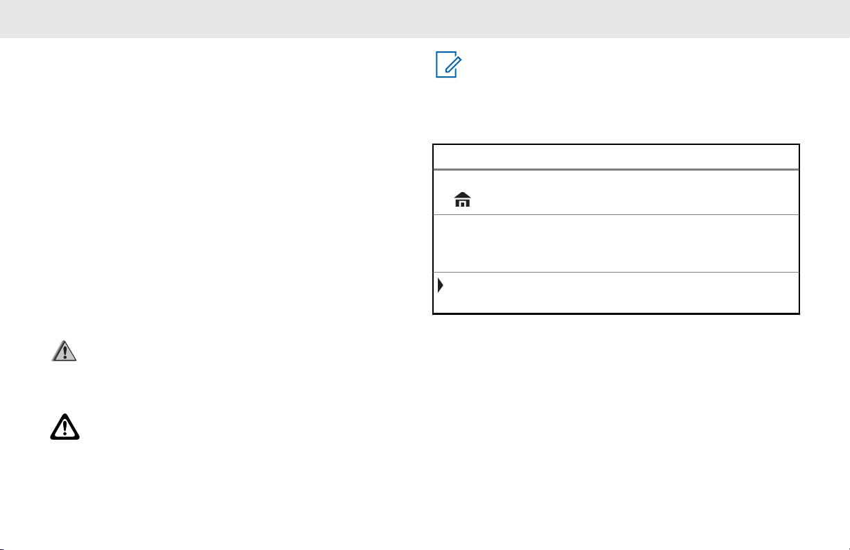
Example Description
Home button
or
Phon
Buttons and keys are shown in bold
print or as an icon.
Menu entries are shown similar to
the way they appear on the display
of the radio.
This means “Press the right side of
the 4-Way Navigation Button”.
19
Page 20
A
English
Radio Maintenance
This chapter covers the radio and battery care.
Radio Care
Proper radio usage and care assures efficient operation
and long life for the product.
The following are recommendations and warnings when
using the radio
CAUTION:
• Your radio casting has a vent port that allows for
pressure equalization in the radio. Never poke
this vent with any objects, such as needles,
tweezers, or screwdrivers.This could create leak
paths into the radio and the radio submergibility
will be lost.
• (For APX 6000/APX 6000Li R Radios Only) Your
radio is designed to be submerged to a
maximum depth of 6 feet, with a maximum
submersion time of 2 hours. Exceeding either
maximum limit may result in damage to the
radio.
20
Page 21

English
• (For APX 6000/APX 6000Li R Radios Only)
Elastomer seals used in portable radios can age
with time and environmental exposure.
Therefore, Motorola Solutions recommends that
radios be checked annually as a preventive
measure in order to assure the waterseal
integrity of the radio. Motorola Solutions details
the disassembly, test, and reassembly
procedures along with necessary test equipment
in the radio service manual.
• If the radio battery contact recess is exposed to
water without the battery attached, dry and clean
the radio battery contacts before attaching a
battery to the radio. Turn the radio over with the
battery contact recess facing down and shake
the radio so any trapped water can escape. The
battery contacts must be dry before attaching a
battery or a short circuit of the contacts could
occur.
• Avoid subjecting the radio to an excess of
liquids. Do not submerge the radio unless it is
ruggedized.(APX 6000/APX 6000Li R model)
• Accessory connector cover must be attached to
the radio side accessory connector if an
accessory is not attached to the radio.
• If the radio is submerged or exposed to a high
force water spray, such as from a hose, remove
the side accessory connector or accessory
connector cover immediately and check to make
sure no water was forced into the accessory
connector/radio interface. Rinse and dry the area
and re-attach the accessory or accessory
connector cover if leakage occurs.
• If the radio is exposed to a corrosive
environment, such as salt water or corrosive
gases or liquids, rinse and clean the radio
immediately to prevent damage to radio
materials, especially plated surfaces. Refer to
Cleaning Your Radio on page 22 for detailed
instructions. Remove the battery and the
antenna before cleaning if exposed to corrosive
environments.
• If the radio has been submerged in water, shake
the radio well so that any water that may be
trapped inside the speaker grille and microphone
port can be removed. Otherwise, the water will
decrease the audio quality of the radio.
• Do not disassemble the radio. This could
damage radio seals and result in leak paths into
21
Page 22
English
the radio. Any radio maintenance should be
performed only by a qualified radio technician.
• CAUTION:
Do not use the radio without an
accessory connector or a dust cover in
place as contamination can build up on
the contacts.
• Underwriter Laboratory (UL) certified radios
should only be opened and serviced by UL
approved service centers. Opening or repairing
at unauthorized locations will invalidate the
radio’s hazardous location rating.
• Do not pound, drop, or throw the radio
unnecessarily.
• When charging the radio using a wall mounted
charger, the radio must be turned off. Otherwise,
the Man Down Alert and Emergency may be
accidentally triggered.
Cleaning Your Radio
CAUTION:
Do not use solvents to clean your radio as most
chemicals may permanently damage the radio
housing and textures.
Do not submerge the radio in the detergent
solution.
To clean the external surfaces of your radio, follow the
procedure described next.
1 Combine one teaspoon of mild dishwashing
detergent to one gallon of water (0.5% solution).
2 Apply the solution sparingly with a stiff, non-metallic,
shortbristled brush, making sure that excess
detergent does not get entrapped near the
connectors, controls, or crevices. Rinse and then dry
the radio thoroughly with a soft, lint-free cloth.
3 Clean battery contacts with a lint-free cloth to
remove dirt or grease.
22
Page 23
English
Radio Service and Repair
Proper repair and maintenance procedures will assure
efficient operation and long life for this product. A Motorola
Solutions maintenance agreement will provide expert
service to keep this and all other communication equipment
in perfect operating condition.
A nationwide service organization is provided by Motorola
Solutions to support maintenance services. Through its
maintenance and installation program, Motorola Solutions
makes available the finest service to those desiring reliable,
continuous communications on a contract basis.
For a contract service agreement, please contact your
nearest Motorola Solutions service or sales representative,
or an authorized Motorola Solutions dealer.
Cleaning the External Surface of the Radio
CAUTION:
Do not use solvents to clean your radio. Spirits may
permanently damage the radio housing.
Do not submerge the radio in detergent solution.
1 Combine one teaspoon of mild diswashing detergent
to one gallon of water (0.5% solution).
2 Apply the solution sparingly with a stiff, non-metallic,
short-bristled brush, making sure excess detergent
does not get entrapped near the connectors, controls
or crevices.
3 Dry the radio thoroughly with a soft, lint-free cloth.
Battery Care
This chapter provides information on the battery charge
status, battery recycling and disposal.
Battery Charge Status
Your radio can indicate the battery’s charge status through:
• the LED and sounds.
• the fuel gauge icon on the display.
You can also check the battery charge status using the
menu entry. See IMPRES Battery Annunciator on page 176
for more information.
LED and Sounds
When your battery is low:
23
Page 24
English
• the LED blinks red when the PTT button is pressed.
• you hear a low-battery “chirp” (short, high-pitched tone).
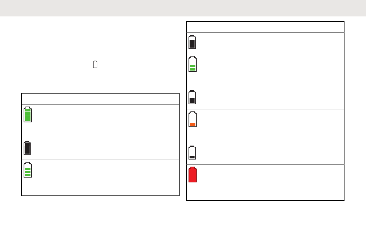
Fuel Gauge Icons
A blinking fuel gauge icon ( ) is displayed only when the
battery voltage drops to low level. In this case, replace the
battery with a fully charged one.
Gauge Battery Charge
76% to 100% full
Top Display:
51% to 75%
Top Display:
1
1
Gauge Battery Charge
26% to 50%
1
Top Display:
11% to 25%
1
Top Display:
10% or less (at 10%, the gauge
begins blinking)
Top Display:
1
These are for IMPRES battery operation only.
24
Page 25
English
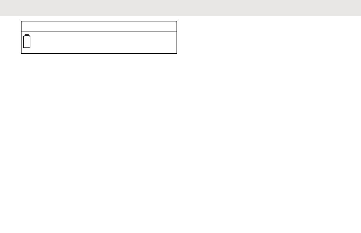
Gauge Battery Charge
Battery Recycling and Disposal
In the U.S. and Canada, Motorola Solutions participates in
the nationwide Call2Recycle program for battery collection
and recycling. Many retailers and dealers participate in this
program.
For the location of the drop-off facility closest to you,
access Call2Recycle's Internet web site at http://
www.call2recycle.org/ or call 1-800-8-BATTERY. This
internet site and telephone number also provide other
useful information concerning recycling options for
consumers, businesses, and governmental agencies.
Additional Performance Enhancement
The following performance enhancements are some of the
latest creations designed to enhance the security, quality,
and efficiency of the radios.
ASTRO 25 Enhanced Data
ASTRO 25 Enhanced Data is optimized to handle different
message sizes and variable update rates from different
applications of the radio. Add Enhanced Data to the
Integrated Data system with a software installation to
improve data channel efficiency and enable denser network
traffic.
Dynamic System Resilience (DSR)
DSR ensures the radio system is seamlessly switched to a
backup master site dynamically in case of system failure.
DSR also provides additional indication such as failure
detection, fault recovery, and redundancy within the system
to address to the user in need. Mechanisms related to the
Integrated Voice and Data (IV&D) or data centric are all
supported by DSR.
CrossTalk Prevention
This feature prevents crosstalk scenarios from happening,
especially when a wideband antenna is used. This feature
allows the adjustment of the internal SSI clock rate of the
radio. This subsequently reduces the possibility of radio
frequency interfering spurs and prevents the issues of
crosstalk.
25
Page 26

English
Encrypted Integrated Data (EID)
EID provides security encryption and authentication of
IV&D data bearer service communication between the
radio and the Customer Enterprise Network.
SecureNet
SecureNet allows user to perform secured communications
on an Analog or Motorola Data Communication (MDC)
channel. The MDC Over-the-Air Rekeying (OTAR) feature
will allow users to perform OTAR activities on an MDC
channel.
P25 Digital Vehicular Repeater System (DVRS)
Motorola Solutions offers an MSI Certified APX compatible,
3rd Party, P25 Digital Vehicular Repeater System (DVRS)
that provides low cost portable radio coverage in areas
where only mobile radio coverage is available and portable
radio coverage is either intermittent or non-existent.
Conventional Talkgroup and Radio Scan Enhancements
A few enhancements have been made to the Conventional
Talkgroup at the system. These enhancements improve the
Scan feature operation significantly when multiple agencies
are using a single conventional radio frequency channel.
These enhancements allow users to use Selective Squelch
to operate on only the subset of talkgroups that are
relevant to the users rather than all talkgroups on the
channel. These Scan improvements have been made to
eliminate the audio holes that were present and to turn on
the busy LED when activity is present on the channel.
Mixed Vote Scan and Standard Conventional Scan
configurations are supported. Priority Operation is also
supported.
Up to 30 different talkgroups can be supported using
conventional channels. A maximum of four talkgroups can
be supported when Vote Scan channels are being used.
Smart PTT is supported with this enhancement as Smart
PTT prevents users from transmitting while other users are
on the channel.
NOTICE:
User Selectable Talkgroups are not compatible with
this Conventional Talkgroup Enhancement.
26
Page 27

What Your Dealer/System Administrator Can Tell You
Check with your dealer or system administrator for the
correct radio settings, if the radio is to be operated in
extreme temperatures (less than -30 °C or more than +60
°C).
You can consult your dealer or system administrator about
the following:
• Is your radio programmed with any preset conventional
channels?
• Which buttons have been programmed to access other
features?
• What optional accessories may suit your needs?
NOTICE:
Specifications may vary for different radio models.
Check with your dealer or system administrator for
more information.
English
27
Page 28
English
Preparing Your Radio for Use
This section provides simple instructions to prepare your
radio for use.
Charging the Battery
WARNING:
To avoid a possible explosion:
• Do not replace the battery in any area labeled
hazardous atmosphere.
• Do not discard batteries in a fire.
The Motorola Solutions-approved battery shipped with your
radio is uncharged. Prior to using a new battery, charge it
for a minimum of 16 hours to ensure optimum capacity and
performance. For a list of Motorola Solutions-authorized
batteries and chargers available for use with your radio,
see Accessories on page 180.
NOTICE:
When charging a battery attached to a radio, turn
the radio off to ensure a full charge.
To charge the battery, place the battery (with or
without the radio) in a Motorola Solutions-approved
charger.
The LED on the charger indicates the charging
progress; see the Charger User Guide.
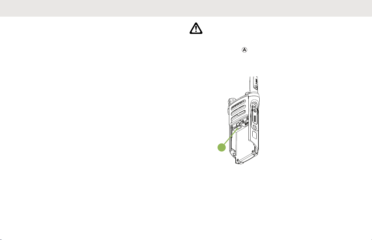
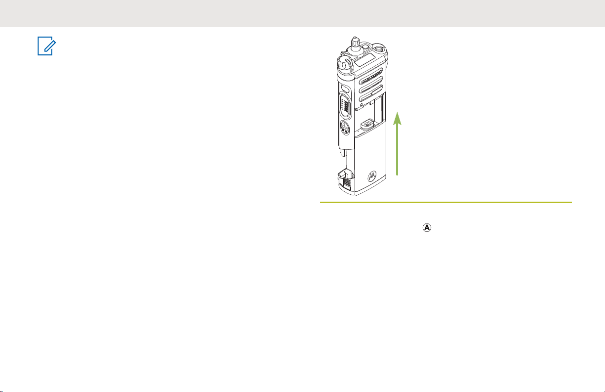
Attaching the Battery
If your radio is preprogrammed with volatile-key retention,
the encryption keys are retained for approximately 30
seconds after battery removal. Check with your dealer or
system administrator for more information.
You can view the status of the battery if the radio is using
an IMPRES battery. See IMPRES Battery Annunciator on
page 176 for more information.
28
Page 29
NOTICE:
User is notified if radio detects non-Motorola
Solutions battery upon powering up, charging, or
removing from the charger. This feature is
applicable for IMPRES and Non-IMPRES battery.
When the radio is attached with the non-Motorola
Solutions battery, a tone sounds, display shows
Unknown Battry temporarily and battery indicator
is not shown in the radio display. Battery menu
screen displays Unknown Battry permanently and
IMPRES battery information is not shown on the
radio display.
1 Slide the battery into the radio frame until the side
latches click into place.
English
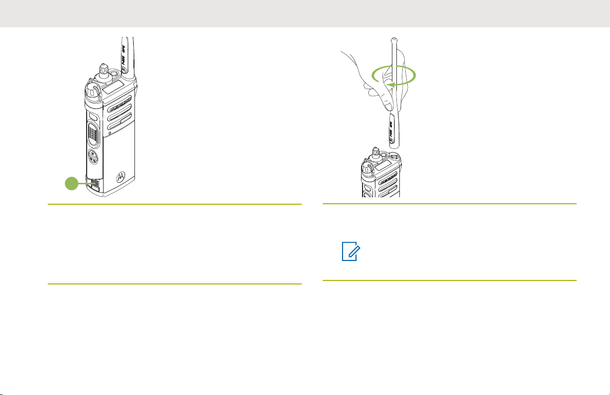
2 To remove the battery, turn the radio off. Squeeze
the release latches
until the battery releases from the radio and remove
the battery from the radio.
at the bottom of the battery
29
Page 30
A
English
Attaching the Antenna
Ensure the radio is turned off before attaching the antenna.
1 Set the antenna in the receptacle.
2 Turn the antenna clockwise to attach to the radio.
3 To remove the antenna, turn the antenna
counterclockwise.
NOTICE:
When removing the antenna, ensure that the
radio is turned off.
30
Page 31

Removing and Attaching the
C
B
A
Accessory Connector Cover
The accessory connector is on the antenna side of the
radio. It is used to connect accessories to the radio.
NOTICE:
To prevent damage to the connector, shield it with
the connector cover when not in use.
1 To remove the accessory connector cover, rotate the
thumbscrew counterclockwise until it disengages
from the radio.
NOTICE:
If the thumbscrew is too tight, use an Allen
wrench at to loosen it first.
English
2 Rotate and lift the connector cover to disengage it
from the radio.
3 To attach the accessory connector cover, insert the
hooked end
connector.
4 Press the top of the cover downward to seat it in the
slot.
of the cover into the slot above the
5
Once in place, tighten by rotating the thumbscrew
clockwise by hand.
31
Page 32

English
Using the Carry Holder
1 Position the radio within the carry holder with the
main speaker facing outward.
3 To remove the radio from the carry holder, place the
tip of your fingers on the ledge of the carry holder.
2 Slide the radio down into the carry holder until it
clicks in place.
32
Page 33

English
4 Push at the bottom of the radio until the radio is
released from it.
Turning On the Radio
1 Rotate the On/Off/Volume Control Knob clockwise
until you hear a click.
33
Page 34

English
• If the power-up test is successful, you see a
splash screen on the radio display, followed by
the Home screen and the Codeplug Alias.
• If the power-up test is unsuccessful, you see
Error XX/YY (XX/YY is an alphanumeric code).
NOTICE:
If the radio fails to power-up after repeating a
few times, record the Error XX/YY code and
contact your dealer.
Codeplug Alias feature is enabled through
Customer Programming Software (CPS)
configuration to display the codeplug alias as
a temporary text during power on.
2 To turn off the radio, rotate the On/Off/Volume
Control Knob counterclockwise until you hear a
click.
34
Page 35

Adjusting the Volume
A
Ensure the radio is powered on and the main speaker is
pointed towards you for increased loudness and
intelligibility, especially in areas with loud background
noises.
English
2 To decrease the volume, rotate this knob
counterclockwise.
1 To increase the volume, rotate the On/Off/Volume
Control Knob
clockwise.
35
Page 36

9
10
11
12
13
8
1
2
3
4
5
6
7
14
21
22
23
24
15
17
16
18
19
20
English
Identifying Radio Controls
This chapter explains the buttons and functions to control
the radio.
Radio Parts and Controls
36
1 Antenna
2 LED
3 Top (Orange) Button
4 Microphone
2
Page 37

English
5 Accessory Connector
6 Home Button
7 4–Way Navigation Button
8 Battery Latch
9 Data Feature Button
10 Menu Select Button
11 Main Display
12 2–Position Concentric Switch
13 3–Position A/B/C Switch
2
14 On/Off/Volume Control Knob
15 16–Position Select Knob
2
16 Top Display
17 Top Side (Select) Button
2
18 Push-to-Talk (PTT) Button
19 Side Button 1
20 Side Button 2
2
2
21 Battery
22 Bluetooth Pairing Location Indicator
23 Main Speaker
24 Microphone
Programmable Features
Any reference in this manual to controls that are
preprogrammed means that a qualified radio technician
2
must use the radio programming software to assign a
feature to a control.
Your dealer can program the programmable buttons as
shortcuts to radio functions or preset channels/groups
depending on the duration of a button press:
Press
Pressing and releasing rapidly.
Long press
Pressing and holding for the preprogrammed duration
(between 0.25 and 3.75 seconds).
Hold down
Keeping the button pressed.
2
These radio controls/buttons are programmable.
37
Page 38

English
Assignable Radio Functions
Bluetooth On/Off
Allows you to turn on/off the Bluetooth.
Bluetooth Configuration
Allows you to access to the Bluetooth menu.
Bluetooth Audio Reroute
Allows you to toggle the audio route between radio
speaker or Remote Speaker Microphone and Bluetooth
headset.
Bluetooth Headset PTT
Keys up the Bluetooth Headset microphone.
Bluetooth Data Devices
Pairs with the data devices for data transfer.
Bluetooth Clear All Pairing
Allows you to clear all pairing information for Bluetooth.
This is accessed by a long press of the Bluetooth
On/Off Button.
Bluetooth Inquiry On/Off
Enables Bluetooth Search feature.
Bluetooth Discoverable On/Off
Enables Bluetooth visibility. This is accessed by a long
press of the Bluetooth Inquiry On/Off Button.
Call Alert
Allows the radio to function like a pager, or to verify if a
radio is active on the system.
Call Response
Allows you to answer a private call.
Channel
Selects a channel.
Contacts
Selects the Contacts menu.
Dynamic Priority (Conventional Only)
Allows any channel in a Scan List (except for the
Priority-One channel) to temporarily replace the PriorityTwo channel.
Emergency
Depending on the programming, initiates or cancels an
emergency alarm or call.
Internet Protocol Address
Display the Internet Protocol (IP) address, device name,
and status of the radio.
Location
Determines the current location (latitude, longitude, time
and date), and also the distance and bearing to another
location or turns the GPS functionality on or off for all
locations.
38
Page 39

English
Man Down Clear
Clears the Man Down mode alarm that is triggered
when your radio achieves or passes a tilt angle
threshold or a combination of the angle threshold and a
motion sensitivity level.
Message
Enters the current message list.
Mode Select
Long-press programs a button with the current zone
and channel of the radio; once programmed, the shortpress of that button changes the radio zone channel to
the programmed zone and channel.
Monitor (Conventional Only)
Monitors a selected channel for all radio traffic until
function is disabled.
Multiple Private Line (Conventional Only)
Selects the Multiple Private Line lists.
Nuisance Delete
Temporarily removes an unwanted channel, except for
priority channels or the designated transmit channel
from the scan list.
One Touch 1–4
Launches a specific feature with one single buttonpress. You can setup as many as four separately
programmed buttons for four different features.
Phone
Allows you to make and receive calls similar to standard
phone calls.
Private Call (Trunking Only)
Allows a call from one individual radio to another.
Private Line Defeat (Conventional Only)
Overrides any coded squelch (DPL or PL) that is
preprogrammed to a channel.
Priority Dispatch
Allows you to call the dispatcher on a different
talkgroup.
Radio Profiles
Allows easy access to a set of preprogrammed visual
and audio settings of the radio.
Recent Calls
Allows easy access to the list of calls recently received
or made.
Rekey Request
Notifies the dispatcher that a new encryption key is
needed.
39
Page 40

English
Repeater Access Button (RAB) (Conventional Only)
Allows user to manually send a repeater access
codeword.
Reprogram Request (Trunking Only)
Notifies the dispatcher that a new dynamic regrouping
assignment is needed.
Request-To-Talk (Conventional Only)
Notifies the dispatcher you want to send a voice call.
Scan
Toggles scan on or off.
Scan List Programming
Selects the scan list for editing (by long press on the
Scan button).
Secure Transmission Select (Conventional and
Trunking)
Toggles the Secure Transmission On or Off when the
Secure/Clear Strapping fields is set to Select for the
current channel and when the radio is model/option
capable.
Selective Call (Conventional Only)
Calls an assigned radio.
Site Display/Search (Trunking Only)
Displays the current site ID and RSSI value; performs
site search for Automatic Multiple Site Select (AMSS) or
SmartZone operation.
Site Lock/Unlock (Trunking Only)
Locks onto a specific site.
Status (Astro 25 Trunking Only)
Sends data calls to the dispatcher about a predefined
status.
Talkaround/Direct (Conventional Only)
Toggles between using a repeater and communicating
directly with another radio.
Talkgroup (Conventional Only)
Allows a call from an individual radio to a group of
radios.
Text Messaging Service (TMS)
Selects the text messaging menu.
TMS Quick Text
Selects a predefined message.
User
Automatically registers the users to the server.
Zone Select
Allows selection from a list of zones.
40
Page 41

B
C
D
E
A
English
Basic Zone Bank
Provides access from up to six zones by toggling
between two banks of three zones, one group of three
(A, B, and C) to a second group of three zones (D, E,
and F).
Enhanced Zone Bank
Provides access from up to 75 zones by toggling
between 25 banks (A, B, ... X or Y) of three zones.
Assignable Settings or Utility Functions
Keypad/Controls Lock
Locks or unlocks the keypad, programmable buttons,
switches or rotary knobs.
Light/Flip
Press the button to toggle the display backlight on or
off; press and hold the button to reverse the content of
the top display.
TX Power Level
Toggles transmit power level between high and low.
Voice Announcement
Audibly indicates the current feature mode, Zone or
Channel the user has just assigned.
Voice Mute
Toggles voice mute on or off.
Volume Set Tone
Sets the volume set tone.
Accessing the Preprogrammed Functions
You can access various radio functions through one of the
following methods.
• A short or long press of the relevant programmable
buttons.
• Use the Menu Select Button.
• Use the Menu Select and Navigation buttons.
41
Page 42

English
A Softkeys
B Menu Select Buttons
C Data Feature Button
D 4–Way Navigation Button
E Home Button
selected radio features, the button is also used to save
user-edited radio settings or information before returning
you to the Home screen.
NOTICE:
Some features do not require you to press to go
to the Home screen. Refer to the individual feature
sections in this manual for further details on saving
user-edited radio settings or information.
Menu Select Buttons
NOTICE:
Check with your dealer or system administrator for
the list of features activated in your radio.
Use the Menu Select button to access the menu entry of
your radio feature. Your radio may be preprogrammed
differently from the following example, but the steps for
selecting a channel may appear as shown below:
Press the Menu Select button directly below Chan .
Home Button
Pressing the button returns you to the Home (default)
screen. In most cases, this is the current mode. For
42
4-Way Navigation Button
Use the 4-Way Navigation Button to scroll up, down, left,
or right with one of the following methods.
• Press and release one of the buttons to scroll from one
entry to the next one.
• Press and hold one of the buttons to have the radio
toggles through the list automatically (release the button
to stop).
Data Feature Button
Use Data Feature button to access data-related features,
such as the Text Messaging Service (TMS) feature screen.
Page 43

A
English
Push-To-Talk (PTT) Button
The PTT button on the side of the radio serves two basic
purposes:
• While a call is in progress, the PTT button allows the
radio to transmit to other radios in the call.
Press and hold down PTT button to talk. Release the
PTT button to listen. The microphone is activated when
the PTT button is pressed.
• While a call is not in progress, the PTT button is used to
make a new call. See Methods to Make a Radio Call on
page 64 for more information.
43
Page 44

English
Identifying Status Indicators
This chapter explains the status indicators used in the
radio.
Status Icons
The 130 x 130 pixel front liquid crystal display (LCD) of
your radio shows radio status, text entries, and menu
entries. The top two display rows contain color icons that
indicate radio operating conditions.
Selected icons are also shown on the first row of the 112 x
32 pixel top monochrome display screen of your radio.
The following icons are for the front display screen unless
indicated otherwise.
Receiving
Radio is receiving a call or data.
Top Display:
Top Display:
Top Display:
Top Display:
Transmitting
Radio is transmitting a call or data.
Call Received
Radio has received an Individual Call.
Battery
For IMPRES battery operation only –
the icon shown indicates the charge remaining in the battery.
For all battery operation – the icon
blinks when the battery is low.
Received Signal Strength Indicator
(RSSI)
The number of bars displayed represents the received signal strength for
the current site (trunking only) The more
stripes in the icon, the stronger the signal.
44
Page 45

English
Top Display:
Top Display:
Top Display:
Roaming
The radio has roamed to and is currently
registered to a foreign system.
Direct
On
Radio is currently configured for direct
radio-to-radio communication (during
conventional operation only).
Off
Radio is connected with other radios
through a repeater.
Monitor (Carrier Squelch)
Selected channel is being monitored
(during conventional operation only).
In-Call User Alert
or
Top Display:
or
Top Display:
Top Display:
On
The feature is enabled. Voice muting of
the affiliated trunking talkgroup or selected conventional channel is activated.
Off
The feature is disabled. Voice muting of
the affiliated trunking talkgroup or selected conventional channel is deactivated.
Power Level
L
Radio is set at Low power.
H
Radio is set at High power.
Scan
Radio is scanning a scan list.
Priority Channel Scan
45
Page 46

English
Top Display:
Top Display:
Top Display:
or
Blinking dot
Radio detects activity on channel designated as Priority-One.
Steady dot
Radio detects activity on channel designated as Priority-Two.
View/Program Mode
Radio is in the view or program mode.
On steady
View mode
Blinking
Program mode
Vote Scan Enabled
The vote scan feature is enabled.
Basic Zone Bank 1
A
Radio is in Zone 1.
Top Display:
or
or
Top Display:
,
,
until
B
Radio is in Zone 2.
C
Radio is in Zone 3.
Basic Zone Bank 2
D
Radio is in Zone 4.
E
Radio is in Zone 5.
F
Radio is in Zone 6.
Enhanced Zone Bank
A
Contains Zone 1, Zone 2, and Zone 3,
B
Contains Zone 4, Zone 5, and Zone 6,
C
Contains Zone 7, Zone 8, and Zone 9,
until
or
46
or
Page 47

English
Top Display:
X
Contains Zone 70, Zone 71, and Zone
72,
Y
Contains Zone 73, Zone 74, and Zone
75.
Secure Operation
On
Secure operation.
Off
Clear operation.
Blinking
Receiving an encrypted voice call.
AES Secure Operation
On
AES secure operation.
Off
Clear operation.
Blinking
Receiving an encrypted voice call.
GPS Signal
On
Feature is enabled and signal is available.
Off
Feature is disabled.
Blinking
Feature is enabled, but no signal is
available.
User Login Indicator (IP Packet Data)
On
User is currently associated with the radio.
Off
User is currently not associated with the
radio.
Blinking
Device registration or user registration
with the server failed due to an invalid
username or pin.
Inverted
User successfully login to the secured
IP Packet Data.
47
Page 48

English
Top Display:
Top Display:
Data Activity
Data activity is present.
Bluetooth On
Bluetooth is on and ready for Bluetooth
connection.
Bluetooth Connected
Bluetooth is currently connected to the
external Bluetooth device.
The radio Wi-Fi® network is connected.
The number of bars displayed represents
the signal strength of the Wi-Fi signal.
Text Messaging Service (TMS) Indicators
Status icons and menu options shown here help you to
work more efficiently with TMS feature. See Text
Messaging Service (TMS) on page 108 for more
information.
TMS Status Icons
The following icons appear on the radio display when you
send and receive text messages.
Inbox Full
The Inbox is full.
Message Sent
The text message is sent successfully.
Message Unsent
The text message cannot be sent.
Unread Message
• User receives a new message.
48
Page 49

English
• The selected text message in the Inbox
has not been read.
Read Message
The selected text message in the Inbox has
been read.
Normal Message
User is composing a message with normal
priority and without a request for a reply.
Message Index
Indicates the index of the current message
the user is viewing.
Example: If the user is looking at the third
message out of a total of six messages in the
Inbox folder, the icon is displayed as the icon
on the left column.
Priority Status
• The “Priority” feature is toggled on before
the message is sent.
• Messages in the Inbox folder are flagged
with “Priority”.
Request Reply
• The “Request Reply” feature is toggled on
before the message is sent.
• Messages in the Inbox folder are flagged
with “Request Reply”.
Priority Status and Request Reply
• User is composing a message with a priority status and a request for a reply.
• Messages in the Inbox folder are flagged
with “Priority” and “Request Reply”.
TMS Menu Options
The following menu options appear on the radio display
when you send and receive text messages.
Menu
Option
Back
Clr
Del
Description/Function
Brings you back to the previous screen.
Deletes all messages.
Deletes a message or text.
49
Page 50

English
Menu
Option
Exit
No
Optn
Rply
Sel
Send
Yes
Description/Function
Exits to the Home screen.
Returns to the previous screen.
Brings you to the Options main screen.
Replies to a message.
Selects the highlighted command.
Sends the message.
Updates or saves a command.
Call Type Icons
The following icons appear on the radio main display, when
you make or receive a call, or view selected call lists, to
indicate the different call types associated with an alias or
ID.
Radio number.
Radio number added to a Call List.
Mobile number.
Mobile number added to a Call List.
Landline phone number.
Landline phone number added to a Call
List.
Incoming call or data.
Outgoing call or data.
Incoming emergency call.
LED Indicator
50
The LED indicator shows the operational status of your
radio.
Page 51

A
Solid red
Radio is transmitting.
Blinking red
Radio is transmitting at low battery condition.
Double blinking red
Radio is in Emergency Mode.
Rapidly blinking red
Radio has failed the self test upon powering up or
encountered a fatal error.
Solid yellow (Conventional Only)
Channel is busy.
Intelligent Lighting Indicators
English
Blinking yellow
Radio is receiving a secured transmission.
Solid green
Radio is powering up, or is on a non-priority channel
while in the Scan List Programming mode.
Blinking green
Radio is receiving an individual or telephone call, or is
on a Priority-Two channel while in the Scan List
Programming mode.
Rapidly blinking green
Radio is on a Priority-One channel while in the Scan
List Programming mode.
NOTICE:
No LED indication when the radio receives a clear
(non-secured) transmission in trunking Mode. LED
indication can be preprogramed by qualified
technician to be permanently disabled. Consult your
dealer for further details if you want to disable it.
This feature temporarily changes the backlight of the top display screen, and adds a color bar to the main display screen
to help signal that a radio event has occurred
51
Page 52

English
NOTICE:
This feature must be preprogrammed by a qualified radio technician.
Backlight and Bar
Color
Orange Emergency Alerts The radio initiates an emergency alarm or call.
Red Critical Alerts The radio battery is low.
Green Call Alerts The radio receives a private call.
Notification When
The radio receives an emergency alarm or call.
The radio initiates the Man Down Post-Alert timer.
The radio initiates Fireground Evacuation alarm.
The radio is out of range.
The radio enters Failsoft mode.
The radio is unable to establish a full connection with the system.
The radio is unable to authenticate or register with the system.
The radio lost GPS signal or GPS function fails.
The radio receives a phone call.
The radio receives a call alert.
The radio receives a selective call.
52
Page 53

English
Backlight and Bar
Color
Notification When
The radio enters Geofence.
Alert Tones
Your radio uses alert tones to inform you of the condition of your radio. The following table lists these tones and when
they occur.
You Hear Tone Name Heard
Short, LowPitched Tone
Long, LowPitched Tone
Radio Self Test Fail When radio fails its power-up self test.
Reject When an unauthorized request is made.
Time-Out Timer Warning Four seconds before time out.
No ACK Received When radio fails to receive an acknowledgment.
Individual Call Warning
Tone
Man Down Entry When radio initiates Man Down mode.
Time-Out Timer Timed Out After time out.
Talk Prohibit/PTT Inhibit (When PTT button is pressed) transmissions are not allowed.
When radio is in an individual call for greater than six seconds
without any activity.
53
Page 54

English
You Hear Tone Name Heard
A Group of
Low-Pitched
Tones
Short, Medium-Pitched
Tone
Lack of Voice PTT Time
out
Out of Range (When PTT button is pressed) the radio is out of range of the sys-
Invalid Mode When radio is on an unpreprogrammed channel.
Busy When system is busy.
Valid Key-Press When a correct key is pressed.
Radio Self Test Pass When radio passes its power-up self test.
Clear Voice At beginning of a non-coded communication.
Priority Channel Received When activity on a priority channel is received.
Emergency Alarm/Call Entry
Central Echo When central controller has received a request from a radio.
When the radio ends your call after it detected there is lack of
voice for 60 seconds after the PTT is pressed and hold. Your radio ends the call to enable your radio to receive calls from other
radio users. The duration of this timer can be preprogrammed by
a qualified radio technician.
tem.
When entering the emergency state.
54
Page 55

You Hear Tone Name Heard
English
Long, Medium-Pitched
Tone
A Group of
Medium-Pitched Tones
Short, HighPitched Tone
(Chirp)
Two HighPitched Tones
Ringing Fast Ringing When system is searching for target of Private Call.
Volume Set When volume is changed on a quiet channel.
Emergency Exit When exiting the emergency state.
Failsoft When the trunking system fails.
Automatic Call Back When voice channel is available from previous request.
Keyfail When encryption key has been lost.
Console Acknowledge When status, emergency alarm, or reprogram request ACK is re-
ceived.
Received Individual Call When Call Alert or Private Call is received.
Call Alert Sent When Call Alert is received by the target radio.
Site Trunking When a SmartZone trunking system fails.
Low-Battery Chirp When battery is below preset threshold value.
GPS Fails When the GPS fails or loses signal.
Enhanced Call Sent When waiting for target of Private Call to answer the call.
Phone Call Received When a land-to-mobile phone call is received.
55
Page 56

English
You Hear Tone Name Heard
Gurgle Dynamic Regrouping (When PTT button is pressed) a dynamic ID has been received.
Talk Permit (When PTT button is pressed) is verifying with the system for ac-
cepting its transmissions.
Unique, LowPitched Chirp
Unique, HighPitched Chirp
IncrementalPitched Tone
DecrementalPitched Tone
A Group of
Very HighPitched Tones
Unique LowHigh Tone
Unique HighLow Tone
56
New Message When a new message is received.
Priority Status When a priority message is received.
Bluetooth Paired When Bluetooth accessory is paired with the radio.
Bluetooth Connected When Bluetooth accessory is connected to the radio.
Bluetooth Unpaired When Bluetooth accessory is unpaired from the radio.
Bluetooth Disconnected When Bluetooth accessory is disconnected from the radio.
Man Down Continuous
Tone
Critical Man Down Continuous Tone
Enhanced Zone Bank Up When EZB Up button is pressed to scroll the Enhance Zone Bank
Enhanced Zone Bank
Down
When radio is in Man Down mode and prepares to transmit Emergency Alarm when the timer of this alarm ends.
When radio is in Man Down Enhanced mode and prepares to
transmit Emergency Alarm when the timer of this alarm ends.
up.
When EZB Down button is pressed to scroll the Enhance Zone
Bank down.
Page 57

English
Phone Call Displays and Alerts
The following phone call displays and alerts appears on the radio display when you make and receive Phone calls. The
radio also uses alert tones to indicate the current status.
You Hear You See When Notes
A Long Tone No phone You press the PTT button
and the phone system is
not available.
Phone busy The phone system is busy.
A Busy Tone Phone busy When a channel is not
available.
– No acknowl-
edge
A High- Pitched Tone
– When you release the PTT
Display Color Change On Channel
This feature provides visual channel identification where
users are able to have a quick visual recognition of being
on a particular channel.
The call is not acknowledged.
button.
Your radio must be preprogrammed to allow you to use this
feature.
When changing channels, the radio backlight on top display
and accessories (DRSM or keypad Mic) changes to the
preprogrammed color.
Press to hang up. The radio returns to the
Home screen.
Press to exit the phone mode and try your
call later.
The radio automatically connects when a
channel opens.
Press to hang up. The radio returns to the
Home screen.
The radio indicates to the landline party that
the caller may begin talking.
57
Page 58

English
The radio backlight on top display changes to white and if
connected to accessories, the DRSM backlight changes to
white and the keypad mic backlight changes to green for
the following scenarios:
• When changing to or powering up on an invalid
channels such as unprogrammed channels, receiver
frequency error channel and blank channels
For hard key zeroize, key loading, and scan list
programming, the backlight follows the home channel
backlight color.
HAZLOC Battery Type Detection
This feature alerts the user when there is a HAZLOC
certification mismatch between the radio and the battery.
This feature supports IMPRES batteries only.
During power up, if there is a mismatch, the following
scenarios occurs:
• The radio repetitively displays Wrong Battery with red
intelligent backlight
• The radio Voice Announcement announces the
preprogrammed Wrong Battery
• The Battery icon blinks continuously
• A repetitive tone sounds
• LED blinks RED continuously
NOTICE:
The radio does not display any indication when
the radio is connected to the charger, when the
radio and battery match, or when the radio
certification type is configured as "None" in
Customer Programming Software (CPS).
This feature is enabled through CPS configuration. Check
with your dealer or system administrator for more
information.
58
Page 59

English
General Radio Operation
This chapter explains the general radio operations in your
radio.
Selecting a Zone
Your radio must be preprogrammed for you to use this
feature.
A zone is a group of channels. Do one of the following to
select a radio channel. You can use these options
interchangeably depending on your preference and the
programmed functions.
• Select a zone using the preprogrammed Zone (3-
Position A/B/C) switch:
a. Move the preprogrammed Zone (3-Position
A/B/C) switch to the position of the required
zone.
If the zone number entered is unprogrammed, the
display shows Invalid entry. Repeat this step.
b. Press the PTT button to transmit on the displayed
zone channel.
• Select a zone using the radio menu
a. or to Zone and press the Menu Select button
directly below Zone.
b. or to the required zone.
c. Press the Menu Select button directly below Sel
to confirm the displayed zone.
d. Press the PTT button to transmit on the displayed
zone channel.
• Select a zone using the radio menu ZnUp or ZnDn:
or to ZnUp or ZnDn.
a.
b. Press and hold the Menu Select button directly
below ZnUp or ZnDn until the required zone
appears.
Positions of ZnUp and ZnDn on the display may
differ each time you release the Menu Select
button. Read carefully before you press.
c. Press the PTT button to transmit on the displayed
zone channel.
Zone:
Selecting a Radio Channel
59
Page 60

English
A channel is a group of radio characteristics, such as
transmit/receive frequency pairs. Do one of the following to
select a radio channel. You can use the options
interchangeably depending on your preference and the
programmed functions.
• Select a channel using the preprogrammed 16–
Position Select Knob to the desired channel.
a. Rotate the preprogrammed 16–Position Select
Knob to the desired channel.
b. Press the PTT button to transmit on the displayed
zone channel.
• Select a channel using the radio menu Chan :
a. or to Chan.
b. Press the Menu Select button directly below
Chan .
c. or to the required channel.
d. Press the Menu Select button directly below Sel
to confirm the selected channel.
e. Press the PTT button to transmit on the displayed
zone channel.
• Select a channel using the radio menu Channel Up
or Channel Down:
or to ChUp or ChDn.
a.
b. Press the Menu Select button directly below
ChUp or ChDn.
Positions of ChUp and ChDn on the display may
differ each time you release the Menu Select
button. Read carefully before you press.
c. Press the PTT button to transmit on the displayed
zone and channel.
Mode Select Feature
Mode Select allows a long press to save the current zone
and channel of your radio to a programmable button, or a
softkey; then once programmed, the short-press of that
button or softkey changes the transmission to the saved
zone and channel.
There are two methods to save the selected zone and
channel:
• Softkeys
• Programmable buttons
NOTICE:
Your radio must be preprogrammed for you to use
this feature.
60
Page 61

English
Saving a Zone and a Channel to a Softkey
Five softkeys are available for you to save the frequently
used zone and channel.
1 Toggle from your current zone and channel to the
required zone and channel.
2
or to MS1, MS2 ... or MS5.
3 Press and hold the Menu Select button directly
below one of the softkey (MS1–MS5).
You hear a short, medium-pitched tone when the zone and
channel is saved.
NOTICE:
To change the programmed zone and channel,
repeat this procedure.
Short press of the programmed softkey changes
your current transmission to the zone and channel
programmed in this softkey.
Saving a Zone and a Channel to a Button
You can save the frequently used zone and channel to the
programmable buttons.
1 Toggle from your current zone and channel to the
required zone and channel.
2 Press and hold the button you desire to program.
You hear a short, medium-pitched tone when the zone and
channel is saved.
NOTICE:
Repeat this procedure to change the zone and
channel of the programmed button.
Short press of the programmed button changes your
current transmission to the zone and channel
programmed in this button.
Receiving and Responding to a Radio Call
Once you have selected the required channel and/or zone,
you can proceed to receive and respond to calls.
61
Page 62

English
The radio shows different indicators based on the system
the radio is configured.
• The LED lights up solid red while the radio is
transmitting.
• In conventional mode, the LED lights up solid yellow
when the radio is receiving a transmission.
• In trunking mode, there is no LED indication when the
radio receives a transmission.
• If the radio is receiving a secure transmission, the LED
blinks yellow.
Receiving and Responding to a Talkgroup Call
To receive a call from a group of users, your radio must be
configured as part of that talkgroup.
When you receive a talkgroup call (while on the Home
screen) the radio displays the following depending on the
system your radio is configured to:
• For ASTRO Conventional system, the LED lights up
solid yellow. The display shows the talkgroup alias or
ID, and the caller alias or ID.
• For Trunking system, the display shows the caller alias
or ID.
1 Hold the radio vertically 1 to 2 inches (2.5 to 5.0 cm)
from your mouth.
2 Press the PTT button to respond to the call.
The LED lights up solid red.
3 Release the PTT button to listen.
See also Making a Talkgroup Call on page 64 for details
on making a Talkgroup Call.
Receiving and Responding to a Private Call (Trunking Only)
A Private Call is a call from one individual radio to another.
The one-to-one call between the two radios are not heard
by the others in the current talkgroup. The calling radio
automatically verifies that the receiving radio is active on
the system and can display the caller ID.
62
Page 63

English
NOTICE:
With the inactivity timer enabled (optional), when
there is no response from the receiving radio, the
calling radio exits the call with Menu Inactive Exit
tone after the timer expires.
When you receive a Private Call, you hear two alert tones
and the LED blinks green. The display shows Call
received and the call received icon blinks.
1 Perform one of the following actions:
• Press the Menu Select button directly below
Resp.
• Press the Call Response button within 20
seconds after the call indicators begin.
If the caller alias is in the call list, the display shows
the caller alias during the call.
If the caller name is not in the call list, the display
shows the caller ID.
2 Press and hold the PTT button to talk. Release the
PTT button to listen.
3
Press or the Call Response button to hang up
and return to the Home screen.
See also Making a Private Call (Trunking Only) on page
65 for details on making a Private Call.
Receiving and Responding to a Telephone Call (Trunking Only)
This feature allows you to receive calls similar to standard
phone calls from a landline phone.
NOTICE:
With the inactivity timer enabled (optional), if there is
no response to the call after the timer expires, your
radio exits the call with Menu Inactive Exit tone.
When you receive a Telephone Call, you hear a telephonetype ringing and the LED blinks green. The backlight of the
screen and the bar turns green.The display shows Phone
call and the call received icon blinks.
1 Press the Call Response button within 20 seconds
after the call indicators begin.
63
Page 64

English
2 Press and hold the PTT button to talk. Release the
PTT button to listen.
3
Press or the Call Response button to hang up
and return to the Home screen.
See also Making a Telephone Call (Trunking Only) on page
67 for details on making a Telephone Call.
Methods to Make a Radio Call
You can select a zone, channel, subscriber ID, or talkgroup
by using:
• The preprogrammed Zone switch.
• The 16-Position Select Channel Knob.
• A preprogrammed One Touch Call button.
• The Contacts list (see Viewing Details of a Contact on
page 81).
NOTICE:
The radio automatically exits the feature, if the
feature inactivity timer is enabled, when the radio is
left idle and the timer expires. You will hear the
Menu Inactive Exit Tone upon feature exit.
Making a Talkgroup Call
To make a call to a group of users, your radio must be
configured as part of that talkgroup.
1 Turn the 16-Position Select Channel Knob to
select the channel with the desired talkgroup.
2 Hold the radio vertically 1 to 2 inches (2.5 to 5.0 cm)
from your mouth.
3 Press the PTT button to make the call.
The radio shows different indicators based on the
system the radio is configured.
• For ASTRO Conventional system, the LED lights
up solid red. The display shows the talkgroup
alias or ID.
• For Trunking system, the LED lights up solid red.
4 Speak clearly into the microphone.
5 Release the PTT button to listen.
64
Page 65

English
Making a Private Call (Trunking Only)
Your radio must be preprogrammed for you to use this
feature.
This feature allows you to send an individual Call Alert or
page if there is no answer from the target radio.
1 Perform one of the following actions:
• To access this feature using a preprogrammed
button, press the preprogrammed Quick Access
(One-Touch) Private Call button to dial the
preprogrammed ID (number) and initiate the
Private Call. Proceed to step 4.
• or to Call , and press the Menu Select button
directly below Call .
The display shows the last transmitted or
received ID.
2 To select the required ID, perform one of the
following actions:
• Press the Menu Select button directly below
Cnts to scroll through and select the required ID.
• Press the Menu Select button directly below
LNum to go to the last number dialed.
• or to the required ID.
3 Press the PTT button to initiate the Private Call.
The display shows Calling... <Number>.
4 Hold the radio vertically 1 to 2 inches (2.5 to 5.0 cm)
from your mouth.
When you are connected, the display shows the ID
of the target radio.
If no acknowledgment is received, the display shows
No acknowledge.
5 Press and hold the PTT button to talk. Release the
PTT button to listen.
6
Press to return to the Home screen.
Making an Enhanced Private Call (Trunking Only)
Your radio must be preprogrammed to allow you to use this
feature.
65
Page 66

English
This feature allows you to send an individual Call Alert
Page if there is no answer from the target radio. See
Sending a Call Alert Page on page 86 for more
information.
1 Perform one of the following actions:
• To access this feature using a preprogrammed
button, press the preprogrammed Quick Access
(One-Touch) Enhanced Private Call button to
dial the preprogrammed ID (number) and initiate
the Private Call. Proceed to step 4.
• or to Call, and press the Menu Select button
directly below Call.
The display shows the last transmitted or
received ID.
2 To select the required ID, perform one of the
following actions:
• Press the Menu Select button directly below
Cnts to scroll through and select the required ID.
• Press the Menu Select button directly below
LNum to go to the last number dialed.
or to the required ID.
•
3 Press the PTT button to initiate the Private Call.
The display shows Calling... <Number>.
4 Hold the radio vertically 1 to 2 inches (2.5 to 5.0 cm)
from your mouth.
When you are connected, the display shows the ID
of the target radio.
If no acknowledgment is received, the display shows
No acknowledge.
If the target radio does not respond before the time
out, the display shows No answer.
5 Press and hold the PTT button to talk. Release the
PTT button to listen.
6
Press to return to the Home screen.
66
Page 67

English
Making a Telephone Call (Trunking Only)
This feature allows you to make calls similar to standard
phone calls to a mobile or landline phone.
1 Perform one of the following actions:
• To access this feature using a preprogrammed
button, press the preprogrammed Quick Access
(One-Touch) Phone Call button to dial the
preprogrammed phone number. Proceed to step
4.
• or to Phon, and press the Menu Select button
directly below Phon.
The display shows the last transmitted or
received ID.
2 To select the required ID, perform one of the
following actions:
• Press the Menu Select button directly below
Cnts to scroll through and select the required ID.
• Press the Menu Select button directly below
LNum to go to the last number dialed.
• or to the required phone number.
3 Press the PTT button to dial the phone number.
4 Hold the radio vertically 1 to 2 inches (2.5 to 5.0 cm)
from your mouth.
5 When your call is answered, press and hold the PTT
button to talk. Release the PTT button to listen.
6
Press to return to the Home screen.
See Phone Call Displays and Alerts on page 57 for more
information if your call is not answered.
Switching Between Repeater or Direct Operation Button
The Repeater Operation increases the radio coverage area
by connecting with other radios through a repeater. The
transmit and receive frequencies are different.
67
Page 68

English
The Direct or “talkaround operation” allows you to bypass
the repeater and connect directly to another radio. The
transmit and receive frequencies are the same.
Perform one of the following actions:
• Press the preprogrammed Repeater/Direct
switch to toggle between talkaround and repeater
modes.
• or to Dir and press the Menu Select button
directly below Dir.
The display shows Repeater mode if the radio is currently
in Repeater mode.
The display shows Direct mode and the Talkaround icon if
the radio is currently in Direct mode (during conventional
operation only).
Monitor Feature
The monitor feature is used to make sure that a channel is
clear before transmitting.
The lack of static on a digital channel when the users
switch from analog to digital radios is not an indication that
the radio is malfunctioning.
Digital technology quiets the transmission by removing the
noise from the signal and allows only the clear voice or
data information to be heard.
Monitoring a Channel
Do one of the followings to monitor a channel. You can use
these options interchangeably depending on your
preference and the programmed functions.
• Monitoring a Channel with Volume Set button.
a. Select the desired zone and channel.
b. Press and hold the Volume Set button to hear
the volume set tone.
c. Adjust the Volume Control Knob if necessary.
d. Release the Volume Set button.
e. Press and hold the PTT button to transmit.
The LED lights up solid red.
f. Release the PTT button to receive (listen).
• Monitoring a Channel with Monitor button.
a. Press the preprogrammed Monitor button.
b. Adjust the Volume Control Knob if necessary.
68
Page 69

English
c. Press and hold the PTT button to transmit.
The LED lights up solid red.
d. Release the PTT button to receive (listen).
The Carrier Squelch indicator appears on the
display when you monitor a channel using the
preprogrammed Monitor button.
• Monitoring a Channel using the selected zone
channel.
a. Select the desired zone and channel.
b. Listen for a transmission.
c. Adjust the Volume Control Knob if necessary.
d. Press and hold the PTT button to transmit.
The LED lights up solid red.
e. Release the PTT button to receive (listen).
Monitoring Conventional Mode
Your radio may be preprogrammed to receive Private-Line
(PL) calls.
1 Momentarily press the Monitor button to listen for
activity.
The Carrier Squelch indicator appears on the
display.
2 Press and hold the Monitor button to set continuous
monitor operation.
The duration of the button press is programmable.
3 Press the Monitor button again, or the PTT button,
to return to the original squelch setting.
If you try to transmit on a receive-only channel, you
hear an invalid tone until you release the PTT button.
®
69
Page 70

English
Advanced Features
This chapter explains the operations of the features
available in your radio.
Advanced Call Features
This chapter explains the operations of the call features
available in your radio.
Selective Call (ASTRO Conventional Only)
A Selective Call is a call from an individual radio to another
individual radio with privacy.
Receiving a Selective Call
When you receive a Selective Call, the radio indicates one
of the followings:
• You hear two alert tones and the LED lights up solid
yellow to indicate the transmitting radio is still sending
signal. The call received icons blinks and the display
shows Call received.
• The LED blinks solid green once to indicate the
transmitting radio is pending to receive signal.
The speaker unmutes.
1 Hold the radio vertically 1 to 2 inches (2.5 to 5.0 cm)
from your mouth.
2 Press and hold the PTT button to talk. Release the
PTT button to listen.
Making a Selective Call
Your radio must be preprogrammed for you to use this
feature.
1 Perform one of the following actions:
• To access this feature by using a preprogrammed
button, press the preprogrammed Quick Access
(One-Touch) Selective Call button to dial the
preprogrammed ID. Proceed to step 3.
or to Call, and press the Menu Select button
•
directly below Call.
The display shows the last transmitted or
received ID.
70
Page 71

English
2 To select the required ID, perform one of the
following actions:
• Press the Menu Select button directly below
Cnts to scroll through and select the required ID.
• Press the Menu Select button directly below
LNum to go to the last number dialed.
• or to the required ID.
3 Hold the radio vertically 1 to 2 inches (2.5 to 5.0 cm)
from your mouth.
4 Press and hold the PTT button to start the Selective
Call.
The display shows the ID of the target radio.
5 Release the PTT button to listen.
6
Press to return to the Home screen.
Talkgroup Call Feature (Conventional Operation Only)
This feature allows you to define a group of conventional
system users so that they can share the use of a
conventional channel.
NOTICE:
Encryption keys are associated to talkgroups. When
talkgroups are associated, encryption keys are
changed by changing the active talkgroup. See
Secure Operations on page 116 for more
information.
Selecting a Talkgroup
1
or to Tgrp and press the Menu Select button
directly below Tgrp.
The display shows the last Talkgroup that was
selected and stored.
2 Perform one of the following actions:
• or to Preset for the preset preprogrammed
Talkgroup.
71
Page 72

English
• or to the required Talkgroup.
3
Press the Menu Select button directly below Sel to
save the currently selected Talkgroup and return to
the Home screen.
If the encryption key associated to the new
Talkgroup is erased, you hear a momentary key fail
tone and the display shows Key fail.
If the encryption key that is associated to the new
Talkgroup is not allowed, you hear a momentary key
fail tone and the display shows Illegal key.
4
Press to return to the Home screen.
Sending a Status Call
This feature allows you to send data calls to the dispatcher
about a predefined status.
Each status can have up to a 14-character name. A
maximum of eight status conditions is possible.
NOTICE:
The radio automatically exits the feature, if the
feature inactivity timer is enabled. You will hear the
Menu Inactive Exit Tone upon feature exit.
1 Perform one of the following actions:
• Press the preprogrammed Status button.
• or to Sts and press the Menu Select button
directly below Sts.
The display shows the last acknowledged status call,
or the first status in the list.
2 or to the required status.
3 Press the PTT button to send the status.
When the dispatcher acknowledges, you hear four
tones and the display shows Ack received. The
radio returns to normal dispatch operation.
If no acknowledgment is received, you hear a lowpitched tone and the display shows No
acknowledge.
72
4
Press
to return to the Home screen.
Page 73

English
No traffic is heard on trunked channels while Status
Calls is selected. If the radio detects no Status Call
activity for six seconds, an alert tone sounds until
you press or the PTT button.
Making a Priority Dispatch Calls
If a talkgroup is congested, the Priority Dispatch feature
allows you to call the dispatcher on a different talkgroup.
This talkgroup is called the Priority Talkgroup. Each
trunking talkgroup can have its own assigned Priority
Talkgroup.Priority Dispatch is not available during
Emergency operations. Scan feature is suspended when
Priority Dispatch is initiated.
Dispatch console that supports this feature must be
preprogrammed to use this feature. Check with your dealer
or system administrator for more information on dispatch
console supporting this feature.
1 Press the preprogrammed Priority Dispatch button.
A tone sounds and the radio enters Priority Dispatch
mode. The radio exits this mode when the Priority
Dispatch Time Out Timer expires.
2 Before the Priority Dispatch Time Out Timer expires,
press and hold the PTT button to transmit.
The display shows the Priority Talkgroup alias.
3 Release the PTT button to listen.
The radio exits Priority Dispatch mode, returns to its
original talkgroup, and displays the home channel
alias.
Responding to the Dynamic Regrouping Feature (Trunking Only)
This feature allows the dispatcher to temporarily reassign
selected radios to a particular channel where they can
communicate with each other. This feature is typically used
during special operations and is enabled by a qualified
radio technician.
You will not notice whether your radio has this feature
enabled until a dynamic regrouping command is sent by
the dispatcher.
73
Page 74

English
NOTICE:
If you try to access a zone or channel that has been
reserved by the dispatcher as a dynamically
regrouped mode for other users, you hear an invalid
tone.
When your radio is dynamically regrouped, it automatically
switches to the dynamically regrouped channel. You hear a
Gurgle tone and the display shows the dynamically
regrouped channel’s name.
Press the PTT button to talk. Release PTT button to
listen.
When the dispatcher cancels dynamic regrouping, the radio
automatically returns to the zone and channel that you
were using before the radio was dynamically regrouped.
Requesting a Reprogram (Trunking Only)
This feature allows you to notify the dispatcher when you
want a new dynamic regrouping assignment.
Perform one of the following actions:
• Press the preprogrammed Reprogram Request
button to send reprogram request to the
dispatcher.
or to Rpgm then press the Menu Select button
•
directly below Rpgm to send reprogram request to
the dispatcher.
The display shows Reprogram Rqst and Please
wait.
If you hear five beeps, the dispatcher has acknowledged
the reprogram request. The display shows Ack received
and the radio returns to the Home screen.
If the dispatcher does not acknowledge the reprogram
request within six seconds, you hear a low-pitched alert
tone and the display shows No acknowledge. Try again or
press
to cancel and return to the Home screen.
Classification of Regrouped Radios
The dispatcher can classify regrouped radios into either of
two categories:
Select Enabled
Select-enabled radios are free to change to any
available channel, including the dynamic-regrouping
channel, once the user has selected the dynamicregrouping position.
74
Page 75

English
Select Disabled
Select-disabled radios cannot change channels while
dynamically regrouped. The dispatcher has forced the
radio to remain on the dynamic-regrouping channel.
The Scan or Private Call feature cannot be selected while
your radio is Select Disabled.
Dynamic Zone Programming (DZP)
NOTICE:
Your radio must be preprogrammed to allow you to
use this feature. This feature works on the condition
at least one zone in the radio must be a nondynamic zone.
This feature provides one or more Dynamic Zones to store
frequently used channels be it conventional or trunking.
These dynamic channels are saved from pre-existing (nondynamic) channels in the radio. This saves the time and
effort from the regular navigation around the working zones
and channels. User can also delete or update the list in the
Dynamic Zone.
Entering the Dynamic Zone to Select a Dynamic Channel
1
or to Zone then press the Menu Select button
directly below Zone.
The display shows the Zone screen.
2
or to <# Dynamic Zone Channels>.
3 Perform one of the following actions:
• Press the Menu Select button below Sel to
select.
• Press the Menu Select button below Exit to exit.
If you have selected one of the Dynamic Zone
Channels list, the display returns to Home screen
with the selected <# Dynamic Zone Channels>
shown on the screen.
If you have selected Exit without selecting any
Dynamic Zone Channels list, the display returns to
Home screen without any changes.
3
3
3
# indicates number of the channel on the 16-Position Switch which are numbered from 1 to 16.
75
Page 76

English
Saving a Channel in the Dynamic Zone from List Selection
The radio must be in Dynamic Zone in order to perform this
operation.
1
or to ZnPr. Press the Menu Select button directly
below ZnPr to enter Program Zone screen.
2
Press the Menu Select button directly below Edit.
The display shows Search Options screen.
3
or to List Selection. Press the Menu
Select button directly below Sel .
The display shows Select Zone screen.
4 or to the required zone. Press the Menu
Select button directly below Sel .
The display shows Select Chan screen.
5 or to the required channel. Press the Menu
Select button directly below Sel .
The display shows Channel updated.
6
Press the Menu Select button directly below Exit to
return to Home screen.
Deleting a Channel in the Dynamic Zone
The radio must be in Dynamic Zone in order to perform this
operation.
1
or to ZnPr then press the Menu Select button
directly below ZnPr to enter Program Zone screen.
The display shows the dynamic channels list.
2 or to the saved dynamic channel then press
the Menu Select button directly below Del.
The display shows Channel deleted screen.
76
Page 77

English
3
Press the Menu Select button below Exit to return
to Home screen.
The Home screen shows <Dynamic Zone
Channels>.
If the channel deleted is the Home channel, the
Home screen shows <Zone Name>“Blank”.
Zone to Zone Cloning
Zone to Zone Cloning clones conventional zones from one
radio to another. This feature allows you to select the clone
enabled zones from a source radio and clone them into a
target radio.
You can clone the zones by using a cable that connects the
source and target radios.
Connect two radios with a clone cable. The target radio
must be digital, band, and FCC mandate compatible with
the source radio.
1 On the source radio, press the Menu Select button
directly below Clon.
2
Press the Menu Select button directly below Sel to
select source zone.
3 When connecting to the target radio, one of the
following scenarios occurs:
• If the radio is compatible, the radio displays
Target radio connected. Proceed to step 4.
• If the radio is not compatible, the radio displays
Target radio incompatible. Press the Menu
Select button directly below Ok and the radio
returns to the previous screen.
Once connected, the zone clone status is displayed
on the right.
4
Press the Menu Select button directly below Next to
accept the source zones selection. One of the
following scenarios occurs:
• If you select a single source zone, press the
Menu Select button directly below Sel to select
the target zones for cloning.
• If you select multi-source zones, the radio
displays Confirm target and shows the
automatically selected target zones and source
zones mapping.
77
Page 78

English
• If the selected multi-source zones exceed the last
clonable target zone, the radio displays <#> src
zones unselected, Sel exceed max tgt
zone, and Protected tgts not supported
alternatively.
5
Press the Menu Select button directly below Clon to
begin cloning.
The radio displays Cloning…<Current cloning zone>.
One of the following scenarios occurs:
• If the cloning is successful, a tone sounds, the radio
displays Clone successful and the source zone alias
is displayed on the right.
• If the cloning is not successful, a tone sounds and the
radio displays Clone failed. Press the Back button to
enter the source zone list.
• If you press the Home button, the radio aborts cloning.
NOTICE:
The target radio enters programming mode during
cloning and resets after cloning is completed.
Contacts
This feature provides “address-book” capabilities on your
radio. Each entry corresponds to an alias (name) or ID
(number) that you use to initiate a call.
Contact entries are alphabetically sorted according to entry
alias. Each alias can have up to five IDs of different call
types associated with it.
Additionally, each entry, depending on context
(conventional, trunking, or phone), associates with one or
more of the four types of calls: Phone Call, Selective Call,
Private Call, or Call Alert.
Each entry within Contacts contains the following
information:
• Call Alias (Name)
• Call ID (Number)
• Call Type (Icon)
• WACN ID (Astro 25 Trunking IDs only)
• System ID
NOTICE:
Your radio must be preprogrammed to allow you to
add, edit, or delete the contact entries.
78
Page 79

English
Your radio also supports a maximum of 50 call lists. Each
list can store up to 100 IDs (numbers).
NOTICE:
Your radio is preprogrammed with a number of
contacts per Call Lists. Check with your dealer or
system administrator for more information.
The radio automatically exits the feature, if the
feature inactivity timer is enabled, when the radio is
left idle and the timer expires. You hear the Menu
Inactive Exit Tone upon feature exit.
Making a Private Call from Contacts
Your radio must be preprogrammed to allow you to use this
feature.
1
or to Cnts and press the Menu Select button
directly below Cnts.
The entries are alphabetically sorted.
2 or to the required subscriber alias.
3
Press the Menu Select button directly below Optn
and proceed to the next step.
4
or to Call and press the Menu Select button
directly below Sel.
5 or to select the call type.
6 Hold the radio vertically 1 to 2 inches (2.5 to 5.0 cm)
from your mouth.
7 Press the PTT button to initiate the call.
During the call, the display shows the subscriber
alias.
8 Press and hold the PTT button to talk. Release the
PTT button to listen.
The LED lights up solid red when the PTT button is
pressed.
If there is no voice activity for a preprogrammed period of
time, the call ends.
If the call reaches the maximum ring time, the call ends.
79
Page 80

English
Adding a Contact to a Call List
1
or to Cnts and press the Menu Select button
directly below Cnts .
The entries are alphabetically sorted.
2 or to the entry you want to add and press the
Menu Select button directly below Optn .
3
or to Add to CallLst and press the Menu
Select button directly below Sel .
4 Perform one of the following actions:
• or to the required Call List and press the
Menu Select button directly below Add to add to
the Call List.
• or to Cncl to cancel and return to the main
screen of Contacts.
The display shows Please wait momentarily before
showing <Entry> added to Call List,
confirming the addition of the contact to the list.
The radio returns to the main display of Contacts.
Removing a Contact from a Call List
1
or to Cnts and press the Menu Select button
directly below Cnts .
The entries are alphabetically sorted.
2 or to the entry you want to delete and press
the Menu Select button directly below Optn .
3
or to Rm frm CallLst and press the Menu
Select button directly below Sel .
The display shows Remove <Entry> frm Call
List?.
4
Press the Menu Select button directly below Yes to
remove the entry from the Call List, or No to cancel
and return to the main display of Contacts.
The display shows Please wait momentarily before
showing <Entry> removed from Call List,
confirming the removal of the contact from the list.
The radio returns to the main display of Contacts.
80
Page 81

English
Viewing Details of a Contact
1
or to Cnts and press the Menu Select button
directly below Cnts .
The entries are alphabetically sorted.
2 or to the entry you want to view and press the
Menu Select button directly below Optn .
3
or to View and press the Menu Select button
directly below Sel .
The display shows all the numbers associated with the
entry.
Scan Lists
Scan lists are created and assigned to individual channels/
groups. Your radio scans for voice activity by cycling
through the channel/group sequence specified in the scan
list for the current channel/group.
Your radio supports different types of Scan Lists:
• Trunking Priority Monitor Scan List
• Conventional Scan List
• Talkgroup Scan List
Please refer to a qualified radio technician for the maximum
number of Scan Lists can be programmed in your radio.
These lists must be preprogrammed by a qualified radio
technician.
Intelligent Priority Scan
Intelligent Priority Scan feature allows you to add or delete
conventional channels and trunking talkgroups from
multiple system into the priority scan lists.
You can add or delete priority scan list members and
assign priorities using the preprogrammed Scan List
Programming button. Radio displays the priority level of
the scanned member.
NOTICE:
Priority-One channel and Priority-Two channel
member may belong to different Talkgroup Scan
systems.
When the radio locks onto a channel in the Intelligent
Priority Scan list, radio scans for higher priority member
within the same Trunking or Conventional system.
81
Page 82

English
Viewing a Scan List
1
or to ScnL and press the Menu Select button
directly below ScnL .
2 or to view the members on the list.
3
Press to exit the current display and return to the
Home screen.
Editing the Scan List
This feature allows you to change scan list members and
priorities.
1 Perform one of the following actions:
• Long press the preprogrammed Scan List
Programming button (side button).
• or to ScnL then press the Menu Select button
directly below ScnL .
The display shows the lists that can be changed.
3 Perform one of the following actions:
• Press the Menu Select button directly below Sel
to add and/or change the priority of the currently
displayed channel in the scan list.
• Press the Menu Select button directly below Del
to delete the currently displayed channel from the
scan list.
• Press the Menu Select button directly below Rcl
to view the next member of the scan list.
4 Perform one of the following actions to select
another channel that needs to be added or deleted
then repeat step 3. Otherwise, proceed to the next
step.
• or to the desired channel.
• Use the 16-Position Select knob to select the
channel.
5 Perform one of the following actions:
• Move the Scan List Programming switch out of
programming position.
2 or to the entry you want to edit.
82
Page 83

English
• Press to exit scan list programming and return
to the Home screen.
See Viewing and Changing the Priority Status on page 83
for more information on how to add and/or change the
priority of the currently displayed channel in the scan list.
Changing the Scan List Status
1 Perform one of the following actions:
• Long press the preprogrammed Scan List
Programming button (side button).
• Move the preprogrammed Scan List
Programming switch to programming position.
The display shows the programming mode icon and
the first list member.
2 or to the member you want to edit.
3 Perform one of the following actions:
• Press the Select button once to add the currently
displayed channel to the scan list.
• Press the Select button one or more times to
change the scan list status icon of the currently
displayed channel.
4 Perform one of the following actions:
• or to select more list members whose scan
status you want to change.
• Use the 16-Position Select knob to select
another scan list member.
5 Move the Scan List Programming switch out of
programming position. Press to exit scan list
programming and return to the Home screen.
Viewing and Changing the Priority Status
Perform one of the following actions:
•
Press the Menu Select button directly below Sel
one or more times to change the priority status of
the current displayed channel.
83
Page 84

English
• Press the Select button one or more times to
toggle between different status of the Scan List
status icon of the current displayed channel.
The radio shows one of following priority status icons
and scenarios:
• A Scan icon indicates that the current channel is
in the scan list as a non-priority channel. The
LED lights up solid green.
• A Priority-One Channel Scan icon indicates that
the current channel is in the scan list as the
Priority-One channel. The LED rapidly blinks
green. You hear all traffic on the Priority-One
channel, regardless of traffic on non-priority
channels.
• A Priority-Two Channel Scan icon indicates that
the current channel is in the scan list as the
Priority-Two channel. The LED blinks green.
• No icon indicates that the current channel is
deleted from the scan list.
Scan
This feature allows you to monitor traffic on different
channels by scanning a preprogrammed list of channels.
Turning Scan On or Off
Perform one of the following actions:
• Press the preprogrammed Scan button to toggle
Scan On or Scan Off to initiate or stop scan.
• Turn the preprogrammed Scan switch to the
Scan on or Scan off position to initiate or stop
scan.
or to Scan and press the Menu Select button
•
directly below Scan.
If the scan is enabled, the display shows Scan on
and the scan status icon.
If the scan is disabled, the display shows Scan Off.
The radio returns to the Home screen.
84
Page 85

English
Making a Dynamic Priority Change (Conventional Scan Only)
While the radio is scanning, the dynamic priority change
feature allows you to temporarily change any channel in a
scan list (except for the Priority-One channel) to the
Priority-Two channel.
This change remains in effect until scan is turned off. Scan
then reverts to the preprogrammed (original) setting.
• Making a Dynamic Priority Change using the
preprogrammed Dynamic Priority button:
a. When the radio locks onto the channel
designated as the new Priority-Two channel,
press the preprogrammed Dynamic Priority
button.
The radio continues scanning the remaining
channels in the list.
Deleting a Nuisance Channel
If a channel continually generates unwanted calls or noise
(termed “nuisance” channel), you can temporarily remove
the unwanted channel from the scan list.
This capability does not apply to priority channels or the
designated transmit channel.
When the radio is locked onto the channel to be
deleted, perform one of the following actions:
• Press the preprogrammed Nuisance Delete
button.
• or to Nuis and press the Menu Select button
directly below Nuis.
The radio continues scanning the remaining channels in
the list.
Restoring a Nuisance Channel
To restore the deleted nuisance channel, perform
one of the following actions:
• Stop and restart a scan.
• Mode change to another channel and back to the
original channel.
• Turn off the radio and then turn it on again.
Nuisance mode delete can be disabled by the
system administrator.
85
Page 86

English
Call Alert Paging
This feature allows your radio to work like a pager.
Even if other users are away from their radios, or if they are
unable to hear their radios, you can send them an
individual Call Alert page. You can also verify if a radio is
active on the system.
Depending on how your radio is programmed, when you
make an Enhanced Private Call, the radio either
automatically sends a call alert page if there is no answer
after the maximum ring time, or when you press the PTT
button.
NOTICE:
This feature must be preprogrammed by a qualified
radio technician.
Receiving a Call Alert Page
When you receive a Call Alert page, you hear four
repeating alert tones and the LED blinks green. The call
received icons blinks and the display shows Page
received.
Press any button to clear the Call Alert page.
See Making a Talkgroup Call on page 64 or Making a
Private Call (Trunking Only) on page 65 for more
information on returning the call.
Sending a Call Alert Page
Do one of the following to send a call alert page:
NOTICE:
If the feature inactivity timer is enabled, your radio
automatically exits the feature when your radio is
left idle long enough for the time to expire. You hear
the Menu Inactive Exit Tone upon feature exit.
• Sending a call alert page using the preprogrammed
Quick Access (One-Touch) Call Alert Paging
button:
a. Press the preprogrammed Quick Access (One-
Touch) Call Alert Paging button to send a page
to the preprogrammed ID.
86
The display shows Paging...<Number>.
Page 87

English
If the call alert page is sent successfully, you hear
a tone and the display shows Ack received.
The radio returns to the Home screen.
If the call alert page is not acknowledged, you
hear a low tone and the display shows No
acknowledge. Press the Menu Select button
directly below Ok to return to the main screen for
Contacts.
• Sending a call alert page using the radio menu
Page :
a. or to Page .
b. Press the Menu Select button directly below
Page .
c. Press the Menu Select button directly below
Cnts to view the required ID, or to the
required ID.
d. Press the PTT button to send the page.
The display shows Paging...<Number>.
If the call alert page is sent successfully, you hear
a tone and the display shows Ack received.
The radio returns to the Home screen.
If the call alert page is not acknowledged, you
hear a low tone and the display shows No
acknowledge. Press the Menu Select button
directly below Ok to return to the main screen of
Contacts.
• Sending a call alert page using the radio menu
Call :
a. or to Call .
b. Press the Menu Select button directly below
Call .
c. or to select the alias or ID, and press the
PTT button to initiate the call.
If the target radio does not respond after a
preprogrammed period of time, the display shows
Send page?.
d. To send the call alert page, press the Menu
Select button directly below Yes . To exit the
screen without sending the call alert page, press
the Menu Select button directly below No .
The display shows Paging...<Alias>.
87
Page 88

English
If the call alert page is sent successfully, you hear
a tone and the display shows Ack received.
The radio returns to the Home screen.
If the call alert page is not acknowledged, you
hear a low tone and the display shows No
acknowledge. Press the Menu Select button
directly below Ok to return to the main screen of
Contacts.
Quick Call II (ASTRO P25 Digital Trunking and Conventional)
This feature allows the user to broadcast a series of
distinct, recognizable tones before a voice transmission
from the dispatcher or a radio.
The broadcasting dispatcher or radio user can select this
alert tone transmission to be sent to an individual
Talkgroup or over the entire system. Specific tone or series
of tones are pre-programmed into the radios to allow the
dispatcher or supervisor to select a list of tones to
broadcast before they make their voice transmission. Each
tone is distinctive to indicate different situation or different
broadcaster. The transmitting radio also plays back the
tones for the broadcaster to listen.
NOTICE:
The receiving radios must be configured with the
Quick Call II tone in order for the radio to sound the
selected tone and also to sound a preconfigured
alert tone after the selected tone has sound.
Initiating a Quick Call II Transmission
The broadcasting or transmitting radio must be preprogrammed to see the tone in the Quick Call II tone list.
The receiving radio must also be pre-programmed to
decode the tone to broadcast.
1
or to QCII, and press the Menu Select button
directly below QCII.
2 or to select the tone to broadcast.
3 Press the PTT to broadcast the selected tone, or
press and hold the PTT to broadcast the selected
tone and transmit with your vocal transmission.
You hear the radio sounds the selected tone. You
can begin your call after the tone ends.
88
Page 89

English
4 Release PTT to listen.
Emergency Operation
The Emergency feature is used to indicate a critical
situation.
If the Top (Orange) button is preprogrammed to send an
emergency signal, this signal overrides any other
communication over the selected channel.
Your radio supports the following Emergency modes:
• Emergency Alarm
• Emergency Call (Trunking Only)
• Emergency Alarm with Emergency Call
• Silent Emergency Alarm
Check with your dealer or system administrator for more
information on the programming of this feature.
Each channel can only assigned one of the Emergency
modes above. The radio responds differently when
pressing the preprogrammed Emergency button in each
channel.
The radio operates in the normal dispatch manner while in
Emergency Call, except if enabled, it returns to one of the
following:
Tactical/Non-Revert
The radio sends emergency alarm and/or make
emergency call on the current selected channel.
Non-Tactical/Revert for Conventional system
The radio reverts to the preprogrammed emergency
channel to send alarm and/or make emergency call.
Non-Tactical/Revert for Trunking system
The radio reverts to the preprogrammed emergency
talkgroup to send alarm and/or make emergency call.
Man Down is an alternate way to activate the Emergency
feature on the condition the Emergency must be set up for
this feature to operate.
The receiving radio distinguishes the two types of
emergency by displaying the following:
• When receiving an Emergency, the radio displays EA
received.
• When receiving a Man Down alarm, the radio displays
MDown received.
The receiving radio mutes any incoming voice, then sounds
an emergency receiving tone. The radio unmutes the voice
after two seconds.
89
Page 90

English
Distinguishing Emergency and Man Down feature is
enabled through CPS configuration. Check with your dealer
or system administrator for more information.
See Man Down on page 101 for details.
Exiting Emergency
Dispatch console that supports this feature can be
programmed to clear the emergency state of the radio.
Check with your dealer or system administrator for more
information on dispatch console supporting this feature.
To exit emergency at any time, press and hold the
preprogrammed Emergency button for about a
second.
NOTICE:
The timer is programmable from 0–6250
milliseconds by a qualified technician.
Exiting Emergency as Supervisor
NOTICE:
Only applicable in Trunking mode.
Radios configured as Supervisor are able to cancel
emergency mode of other radios in a talkgroup without
initiating emergency.
Dispatch console that supports this feature must be
preprogrammed to use this feature.. Check with your dealer
or system administrator for more information on dispatch
console supporting this feature.
To exit emergency:
Emergency
mode
Initiated by
other radios
Initiated by
Supervisor
Action
Press and hold Side Button
1 and short press Emergency button.
Do one of the following:
• Long press Emergency
button.
• Press and hold Side But-
ton 1 and short press
Emergency button.
• Wait for console to clear
emergency.
90
Page 91

English
NOTICE:
The following buttons combination are
supported.
• Radio Side Button 1 and Orange button.
• Radio Side Button 1 and accessory
Orange button.
• Accessory 1-dot Button and radio
Orange button.
• Accessory 1-dot Button and accessory
Orange button.
Sending an Emergency Alarm
This feature allows you to send a data transmission, which
identifies the radio sending the emergency, to the
dispatcher.
NOTICE:
The default timer of Emergency button press to
activate Emergency is 50 milliseconds. This timer is
programmable from 50–6200 milliseconds by a
qualified technician.
Press the preprogrammed Emergency button.
One of the following scenarios occurs:
• The display shows Emergency on the current
zone and channel. You hear a short mediumpitched tone and the LED blinks red momentarily.
• The radio sounds a short low-pitched tone to
indicate that the selected channel does not
support emergency and rejects to launch
emergency mode.
When you receive the dispatcher’s acknowledgment, the
display shows Ack received. Four tones sound, the alarm
ends, and the radio exits the Emergency Alarm mode.
If no acknowledgment is received, the display shows No
acknowledge. The alarm ends when the timer expires and
the radio exits the Emergency Alarm mode.
91
Page 92

English
Sending an Emergency Call (Trunking Only)
This feature gives your radio priority access to a talkgroup.
1 Press the preprogrammed Emergency button.
One of the following scenarios occurs:
• The display shows Emergency on the current
zone and channel. You hear a short mediumpitched tone and the LED blinks red momentarily.
• You hear the radio sounds a short low-pitched
tone to indicate the selected channel does not
support emergency and rejects to launch
emergency mode.
2 Hold the radio vertically 1 to 2 inches (2.5 to 5.0 cm)
from your mouth.
3 Press and hold the PTT button. Speak clearly into
the microphone.
4 Release the PTT button to end the transmission and
wait for a response from the dispatcher.
5 To exit Emergency Call, press and hold the
preprogrammed Emergency button for about a
second.
Sending An Emergency Call With Hot Mic (Trunking Only)
This feature allows you to send an Emergency Call with hot
mic to a group of radios.
Your radio must be programmed for this type of operation.
Your radio microphone is automatically activated, allowing
you to communicate with the group of radios without
pressing the PTT button. This activated microphone state is
also known as hot mic. The hot mic applies to the first voice
transmission from your radio during the Emergency call.
For subsequent transmissions in the same Emergency call,
you must press the PTT button.
Follow the procedure to send Emergency Call with hot mic
on your radio.
1 Press the preprogrammed Emergency button.
One of the following scenarios occurs:
92
Page 93

English
• The display shows Emergency on the current
zone and channel. A tone sounds and the LED
blinks red momentarily.
• A tone sounds to indicate the selected channel
does not support emergency and rejects to
launch emergency mode.
2 Hold the radio vertically 1 to 2 inches (2.5 to 5.0 cm)
from your mouth.
3 The microphone remains active for the hot mic time
specified in the radio's codeplug programming.
4 To exit Emergency Call, press and hold the
preprogrammed Emergency button.
Sending an Emergency Alarm with Emergency Call
This feature gives your radio priority access on a channel
for conventional system, and to a talkgroup for trunking
system.
1 Press the preprogrammed Emergency button.
If successful, the display shows Emergency on the
current zone and channel. You hear a short,
medium-pitched tone and the LED blinks red
momentarily.
The radio exits Emergency Alarm and enters the
Emergency Call state when one of the following
scenarios occur:
• You receive the dispatcher acknowledgment. The
display shows Ack received.
• You receive no acknowledgment. The display
shows No acknowledge.
• You press the PTT button while in the Emergency
Alarm mode.
If unsuccessful, you hear the radio sounds a short
low-pitched tone to indicate the selected channel
93
Page 94

English
does not support emergency and rejects to launch
emergency mode.
2 Hold the radio vertically 1 to 2 inches (2.5 to 5.0 cm)
from your mouth.
3 Press and hold the PTT button. Speak clearly into
the microphone.
4 Release the PTT button to end the transmission and
wait for a response from the dispatcher.
5 To exit Emergency Call, press and hold the
preprogrammed Emergency button for about a
second.
Turning off the radio also cancels the emergency
state.
Sending An Emergency Alarm and Call with Hot Mic
This feature allows you to send an Emergency Alarm and
Call with hot mic to a group of radios.
Your radio must be programmed for this type of operation.
Follow the procedure to send Emergency Alarms and Call
with hot mic on your radio.
1 Press the preprogrammed Emergency button.
If successful, the display shows Emergency on the
current zone and channel. A tone sounds and the
LED blinks red momentarily.
The radio exits Emergency Alarm and enters the
Emergency Call state when one of the following
scenarios occur:
• You receive the dispatcher acknowledgment. The
display shows Ack received.
• You receive no acknowledgment. The display
shows No acknowledge.
If unsuccessful, a tone sounds to indicate the
selected channel does not support emergency and
rejects to launch emergency mode.
2 Hold the radio vertically 1 to 2 inches (2.5 to 5.0 cm)
from your mouth.
3 The microphone remains active for the hot mic time
specified in your radio's codeplug programming.
94
Page 95

English
4 To exit Emergency Call, press and hold the
preprogrammed Emergency button.
Turning off the radio also cancels the emergency
state.
Sending a Silent Emergency Alarm
This feature allows you to send an Emergency Alarm to the
system without triggering any audio or visual indicators.
1 Press the preprogrammed Emergency button.
The display shows no changes, the LED does not
light up, and you hear no tones. The silent
emergency state continues until you perform the
next step.
2 Perform one of the following actions:
• Press and hold the preprogrammed Emergency
button for about a second to exit the Silent
Emergency Alarm mode.
• Press and release the PTT button to exit the
Silent Emergency Alarm mode and enter regular
dispatch or Emergency Call mode.
Change of Channels during Emergency
For ALL Emergency transmissions, when changing
channels:
• If the new channel is also preprogrammed for
Emergency, you can change channels while in
Emergency operation. The emergency alarm or call
continues on the new channel.
• If the new channel is not preprogrammed for
Emergency, the display shows No emergency, and you
hear an invalid tone until you exit the Emergency state
or change to a channel preprogrammed for Emergency.
Emergency Keep-Alive Feature
This feature, when enabled, prevents the radio from being
turned off by using the On/Off Control Knob when the
radio is in the Emergency state.
95
Page 96

English
NOTICE:
The radio only exits the Emergency state using one
of the ways mentioned in the previous sections.
See Sending an Emergency Alarm on page 91,
Sending an Emergency Call (Trunking Only) on
page 92, Sending an Emergency Alarm with
Emergency Call on page 93, or Sending a Silent
Emergency Alarm on page 95.
Emergency Find Me
The Emergency Find Me (EFM) feature is an additional
emergency feature providing information to nearby radios,
utilizing the Bluetooth Low Energy (BT-LE) transmission
from a radio. In an emergency situation, when the user
presses the pre-programmed Emergency button, there will
be periodic EFM beacon transmitted from the radio along
with the other existing emergency activities. The radios
which are near to the transmitting radio and are capable of
receiving BT-LE signals would receive the beacon
transmission. The range of EFM beacon depends on the
environment in which the radios are located.
Check with your dealer or system administrator for more
information on the programming of this feature.
Sending and Receiving Emergency Find Me Beacon
1 Press the pre-programmed Emergency button to
transmit the EFM beacon.
The receiving radio displays Beacon RX and the
transmitting radio Contact ID or alias on the radio
display. In the case of multiple radios transmitting at
one time, the receiving radio displays Multiple
Beacon RX.
2
Press the menu Bcon. The receiving radio displays
the transmitting radios Contact ID and one of the
following RSSI values based on the signal strength
received:
• RSSI-Excellent
• RSSI-Good
• RSSI-Fair
• RSSI-Poor
96
Page 97

NOTICE:
RSSI-Poor will be shown if the distance
between transmit radio and receive radios
are more than 8 to 10 meters in an open
environment.
Fireground
The portable Fireground Communications System is
designed for deployment at an incident scene. It consists of
central components:
• Your APX portable radios
• Incident Management Software
• Command Terminal
• Radio Frequency (RF) Modem (Conventional Only)
• Control Channel Radio (Trunking)
• Optional Data Radio (Trunking)
• Accountability Server (Trunking)
• DVRS (Optional)
English
These components provide on-scene and inbuilding radio
coverage, and enhanced personnel accountability and
monitoring.
The radio helps to indicate your presence on the scene if it
is in the range of the Incident Commander command
terminal, or trunking radio system.
Each Fireground Communication System radio
automatically reports your radio ID on the commander
mobile command terminal. Your name, riding position and
sector are all can be configured to be seen at the
Commander’s command terminal.
If you have a critical situation, you can press the
Emergency button which activates an alarm on the Incident
Management Software at the command terminal.
The command terminal receives the following status
updates from your radio:
• Powering up or down the radio
• Automatic response to Polling
• Response to Evacuation commands
• Pressing the PTT button to make voice transmission
• Sending an Emergency Alarm and Call
• Entering or Exiting a Trunking Talkgroup
97
Page 98

English
Entering Fireground Zone Channel (Conventional)
1 Upon powering up, one of the following scenarios
occurs:
• If the Fireground Zone Channel is set as default,
you hear the gurgle tone and the radio displays
the home screen. You are in Fireground zone
channel.
• If the Fireground Zone Channel is set as default,
but you hear a short, low-pitched tone, the
display shows Reg failed to indicate that the
command terminal does not respond to
Fireground Zone Channel. Get a qualified
technician for assistance.
• If your home channel is not Fireground Zone
Channel, toggle or change the radio zone
channel to Fireground Zone Channel.
If you are entering Fireground Trunking Talkgroup,
upon powering up, ensure that the Fireground
Trunking Talkgroup is selected. The subscriber unit
automatically appears on the Incident Commander's
terminal.
2 Listen for a transmission. Adjust the Volume
Control Knob if necessary.
3 Perform one of the following actions:
• Press and hold the preprogrammed Volume Set
button to hear the volume set tone. Adjust the
Volume Control Knob if necessary. Release the
Volume Set button.
• At the desired Fireground zone and channel,
press the preprogrammed Monitor button and
listen for activity. Adjust the Volume Control
Knob if necessary.
• If your radio is working in Fireground Zone
Channel, proceed to next step.
4 Press and hold the PTT button to transmit. The LED
lights up solid red while transmitting. Talk into the
microphone clearly if needed.
5 Release the PTT button to receive.
You hear a Transmit End Tone.
98
Page 99

English
Sending Evacuation Tone
This feature enables the evacuation tone to be heard on
the transmitting radio and on any radio that is able to
receive the tone instruction.
Press and hold the PTT button and then short press
the Top (Orange) button.
Once the tone begins to sound, if the orange button is
released the tone continues to alarm on all radios within the
talkgroup, until the PTT button is released.
NOTICE:
Radio does not transmit evacuation tone if the radio
is in secure mode.
Responding to Evacuation Indicator
The Incident Commander can trigger one of sixteen
Tactical Alerts from the Command Terminal. These alerts
can target individuals or groups of users within the
Fireground Communication System. The ergonomic (visual
and audible) response for the Tactical Alerts can be
customized.
Your radio sounds the audible response at the profile
maximum alert tone volume level. The display shows the
configurable programmed alert text and intelligent lighting.
Perform one of the following actions:
• Press the radio Top Side button.
• Press the RSM Side Button 1 if the radio is
connected to RSM.
• Press the PTT button. PTT button must be
configured in CPS to enable this function.
The radio cancels the indications, a tone sounds and
the radio sends an acknowledgment to the command
terminal.
NOTICE:
Move the Volume Control Knob to adjust
the volume of the audible alert from full
volume.
99
Page 100

English
Tactical Public Safety (TPS) (Conventional Only)
TPS enables the user of a group to identify the start and
the end of a transmission by displaying the caller name or
ID on the radio display.
Using TPS Normal Transmission
At TPS Zone Channel, perform one of the following
actions:
• Press PTT button to transmit. Talk clearly into the
microphone. Release PTT button to listen.
• Receive and listen to call, the radio displays the
caller’s name or ID.
Using TPS Emergency Transmission
The following are two important alert tones designed for
this feature.
Emergency Beacon
During Emergency if the TPS radio user pushes the
Emergency button, the radio sounds a Beacon at the
maximum volume of the radio at radio’s internal speaker
and it is not adjustable. This beacon goes to silent when
user presses the PTT button for voice transmission.
Emergency Call De-Key Sidetone
The radio sounds an alert tone to remind radio user that
the Emergency Mode is still active after user releases
the PTT button for an Emergency call transmission. The
volume of loudness depends on the maximum tone at
your radio profile.
1 Press the Emergency button to enter Emergency
Mode.
You hear the Emergency Beacon.
2 Press PTT button to make an Emergency Call.
3 Release to listen.
You hear Emergency Call De-Key Sidetone. After a
short pause, you hear Emergency Beacon.
4 Long press Emergency button to exit Emergency
mode and cancel Emergency Beacon.
100
 Loading...