

Motorola 92FT7058 Users Manual
SYSTEM RELEASE 4.0 VSM
PUBLIC SAFETY LTE
VML750 LTE
Vehicular
Subscriber Modem
(VSM) Installation
Guide

Contact Us
Motorola Solution Support Center
The Solution Support Center (SSC) is the primary Motorola Solutions support contact. Call:
•
Before any software reload.
•
To confirm troubleshooting results and analysis before removing and replacing a Field
Replaceable Unit (FRU) and Field Replaceable Entity (FRE) to repair the system.
For... Phone
United States Calls 800-221-7144
International Calls 302-444-9800
North America Parts Organ izat io n
For assistance in ordering replacement parts or identifying a part number, contact the
Motorola Parts organization. Your first response when troubleshooting your system is to call
the Motorola SSC.
For... Phone
Phone Orders 800-422-4210 (US and Canada Orders)
For help identifying an item or part number, select
choice 3 from the menu.
302-444-9842 (International Orders)
Includes help for identifying an item or part number
and for translation as needed.
Fax Orders 800-622-6210 (US and Canada Orders)
Comments
Send questions and comments regarding user
documentation to
documentation@motorolasolutions.com.
Provide the following information when reporting a documentation error:
•
The document title and part number
•
The page number with the error
•
A description of the error
We welcome your feedbac k on this and other Motoro la m anuals. To tak e a short, conf idential
survey on Motorola Customer Documentation, go to docsurvey.motorolasolutions.com or
scan the following QR code with your mobile device to access the survey.
6802988C54-D
ii

Contact Us
Latest Manual Versio n s
You can verify the latest version of this manual at https://businessonline.motorolasolutions.com.
iii

Copyrights
The Motorola products described in this document may include copyrighted Motorola computer
programs. Laws in the United States and other countries preserve for Motorola certain exclusive
rights for copyrighted computer programs. Accordingly, any copyrighted Motorola computer
programs contained in the Motorola products described in this document may not be copied or
reproduced in any manner without the express written permission of Motorola.
©
2016 Motorola Solutions, Inc. All Rights Reserved
No part of this document may be reproduced, transmitted, stored in a retrieval system, or
translated into any language or computer language, in any form or by any means, without the
prior written permission of Motorola Solutions, Inc.
Furthermore, the purchase of Motorola products shall not be deemed to grant either directly or
by implication , es topp el or otherwise, any license under the copyrights, patents or patent
applications of Motorola, except for the normal non-exclusive, royalty-free license to use that
arises by operation of law in the sale of a product.
Disclaimer
Please note that certain features, fac ilit ies, and capa bi lities des cr ibed in this doc u ment may not
be applicable to or licensed for use on a particular system, or may be dependent upon the
characteristics of a particular mobile subscriber unit or configuration of certain parameters.
Please refer to your Motorola contact for further information.
Trademarks
MOTOROLA, MOTO, MOTOROLA SOLUTIONS, and the Stylized M Logo are trademarks
or registered trademarks of Motorola Trademark Holdings, LLC and are used under license.
All other trademarks are the property of their respective owners.
European Union (EU) Waste of Electrical and Electronic Equipment (WEEE) directive
The European Union's WEEE directive requires that products sold into EU countries must
have the crossed out trash bin label on the product (or the package in some cases).
As defined by the WEEE directive, this cross-out trash bin label means that customers and
end-users in EU countries should not dispose of electronic and electrical equipment or
accessories in household was te.
Customers or end-users in EU countries should contact their local equipment supplier
representative or service centre for information about the waste collection system in their
country.
iv

Document History
Edition Description Date
Release 2.0
Release 3.0
Release 4.0
Second release of VML750 — LTE Vehicular Sub-
scriber Modem (VSM) Installation Guide
Third release of VML750 — LTE Vehicular Subscriber
Modem (VSM) Installation Guide
Forth release of VML750 — LTE Vehicular Subscriber
Modem (VSM) Installation Guide
.
July 2014
July 2015
September 2016
v

Contents
Contact Us ........................................................................................................... ii
Copyrights .......................................................................................................... iv
Document History ............................................................................................... v
Contents .............................................................................................................. vi
List of Figures ................................................................................................... viii
List of Tables ...................................................................................................... ix
List of Procedures ................................................... E rr or ! Book mar k not defined.
About VML750 LTE Vehicular Subscriber Modem (VSM) Installation Gui de . 1
What Is Covered In This Manual? .................................................................................................................... 1
Helpful Background Information ....................................................................................................................... 1
Required Documents for Complete VSM Deployment ..................................................................................... 2
Safety and Regulatory Information ................................................................................................................... 2
FCC Interference .............................................................................................................................................. 2
Legal Notice ..................................................................................................................................................... 2
VML750 Description ............................................................................................ 3
VML750 Models ............................................................................................................................................... 4
VML750 Front Panel ........................................................................................................................................ 5
VML750 Back Panel ......................................................................................................................................... 6
VML750 Installation ............................................................................................. 7
VML750 Unpacking and Inspection .................................................................................................................. 7
Safety and General Information ....................................................................................................................... 7
VML750 Installation Planning ........................................................................................................................... 9
Cable Routing ...................................................................................................................... 10
Cable Holes .................................................................................................................................................... 10
Tools and Equipment ........................................................................................................... 10
Mounting the VML750 Antennas .................................................................................................................... 11
Special Antenna Installation Considerations ....................................................................... 12
Installing Antenna Cables .................................................................................................... 12
VML750 Cables .............................................................................................................................................. 17
Mounting the VML750 .................................................................................................................................... 18
VML750 Cable Routing and Connection ........................................................................................................ 19
Installing the DC Power and Ignition Cable ......................................................................... 19
Installing the LAN/Ethernet Cable ........................................................................................ 21
Installing the Micro USB Cable ............................................................................................ 21
Installing the SIM ............................................................................................................................................ 22
Replacing the CRYPTR Card ......................................................................................................................... 22
Powering Up the Modem ................................................................................................................................ 24
VML750 Troubleshooting Causes and Indicators .......................................... 27
vi

VML750 Troubleshooting ............................................................................................................................... 27
LED Indications .............................................................................................................................................. 29
VML750 Operation ............................................................................................. 31
VLM750 Specifications ..................................................................................... 33
VML750 Physical Specifications .................................................................................................................... 33
VML750 Communication Ports ....................................................................................................................... 33
VML750 RF Ports ........................................................................................................................................... 33
VML750 Power Port ....................................................................................................................................... 33
VML750 LEDs ................................................................................................................................................ 33
VML750 Operating Temperature .................................................................................................................... 33
VML750 Power Specifications ........................................................................................................................ 35
VML750 RF Characteristics ........................................................................................................................... 35
VML750 Replacement Parts List .................................................................................................................... 38
VML750 Kit Replacement Parts List ............................................................................................................... 38
VML750 Approved Antennas and Cables Replacements List ........................................................................ 39
LTE LMR Antennas Mounting Recommendations ......................................... 40
Police Patrol Vehicle Antennas Location Considerations Overview ............................................................... 40
vii

List of Figures
Figure 1 VML750 General View .................................................................................................. 3
Figure 2 Front Panel ................................................................................................................... 5
Figure 3 Back Panel ................................................................................................................... 6
Figure 4 VML750 Dimensions .................................................................................................... 9
Figure 5 Schematic Installation Diagram for Sub-models FLN1057A/FLN2057A WWAN1 &
WWAN2 Configuration ............................................................................................................. 13
Figure 6 Schematic Installation Diagram for Sub-models WWAN1 only
FLN1057A/FLN2057A .............................................................................................................. 14
Figure 7 Schematic Installation Diagram for Sub-models WWAN2 Only
FLN1057A/FLN2057A/FLN5057A/FLN5058A ........................................................................... 15
Figure 8 Schematic Installation Diagram for Sub-model FLN5059A ......................................... 16
Figure 9 Available Cables ......................................................................................................... 17
Figure 10 Mounting the VML750 ............................................................................................... 18
Figure 11 DC Power and Ignition Cable Routing Into Engine Compartment ............................. 19
Figure 12 opening the CRYPTR Card Door .............................................................................. 22
Figure 13 Installing the CRYPTR Card ..................................................................................... 24
viii

List of Tables
Table 1 Legend for General View ............................................................................................... 3
Table 2 Legend for Front Panel .................................................................................................. 5
Table 3 Legend for Back Panel................................................................................................... 6
Table 4 Troubleshooting the VML750 ....................................................................................... 27
Table 5 LED Indicators Function .............................................................................................. 29
Table 6 VML750 Replacement Parts List .................................................................................. 38
ix

x

6802988C54-D
About VML750 LTE Vehicular Subscriber Modem (VSM) Installation Guide
Send Feedback
About VML750 LTE Vehicular
Subscriber Modem (VSM) Installation
Guide
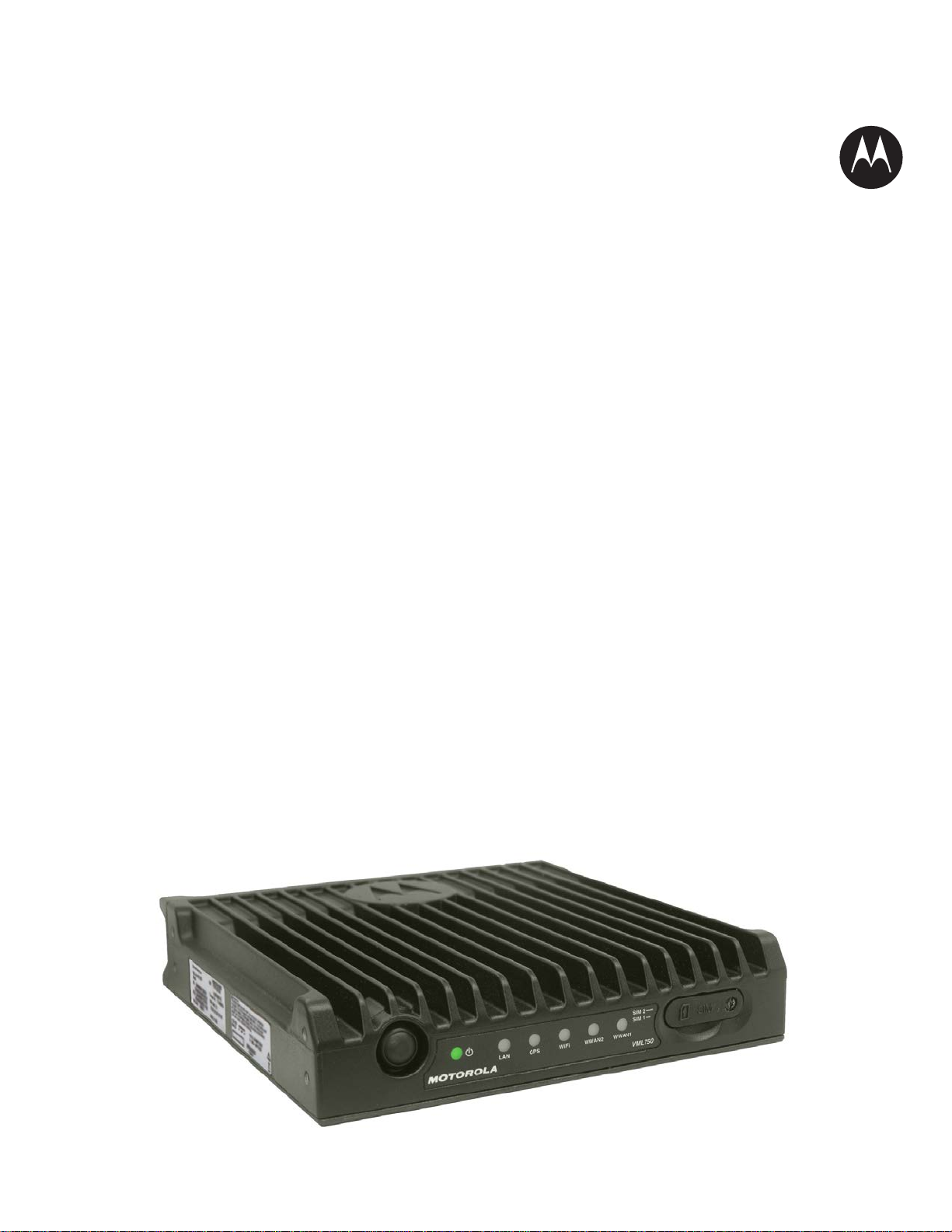
The VML750 LTE Vehicular Subscriber Modem (VSM) connects the patrol car, fire apparatus or
command vehicle to an LTE network, bringing the benefits of wireless broadband to the vehicle. This
installation guide provides a description, and installation, troubleshooting, and operating information.
What Is Covered In This Manual?
The VML750 LTE VSM Installation Guide provides general instructions for installing, operating, and
troubleshooting the VML750.
The guide is organized as follows:
•
VML750 Description provides the product overview.
•
VML750 Installation provides unpacking instructions and all required procedures for installing
the VML750.
•
VML750 Troubleshooting Causes and Indicators provide details regarding possible malfunctions
that may occur after first-time installation of the VML750, their probable cause, and the
recommended corrective actions.
•
Powering Up the Modem provides general information regarding the use of the VML750.
•
VLM750 Specifications provides the VML750 modem specifications.
•
VML750 Replacement Parts List provides part numbers information for the modem and
Antennas.
•
LTE LMR Antennas Mounting Recommendations provides procedures for determining the
mounting locations for a Public Safet y Narro w Ba nd LMR 700/8 00 MH z anten na and Br oa d Band
LTE 700 MHz Antennas.
Helpful Background Information
Motorola offers various courses designed to assist in learning about the system. For information, go to
http://www.motorolasolutions.com/training to view the current course offerings and technology paths.
1

6802988C54-D
About VML750 LTE Vehicular Subscriber Modem (VSM) Installation Guide
2
Send Feedback
Required Documents for Complete VSM Deployment
To complete the full deployment of the modem, you may need the following documents:
•
Information related to VML750 configuration in the VML750 Configuration Guide P/N 6802988C55
https://businessonline.motorolasolutions.com
at:
•
Information related to VML750 monitoring can be found in the VML750 LTE Vehicle Subscr ib er
Modem (VSM) Status Utility Quick Reference Guide P/N 6802988C79.
•
Information related to the device licensing can be found in the Device Licensing Quick Reference
Guide P/N 6871024P25 at:
https://businessonline.motorolasolutions.com
Safety and Regulatory Information
Before installing/using this product, the installer/operator must be familiar with the RF energy
awareness information and operating instructions in the “Product Safety and RF Energy Exposure
Booklet for Mobile Two-Way Radios Installed in Vehicles or as Fixed Site Control Stations” enclosed
with the VML750 LTE Vehicular Subscriber Modem (For USA) Motorola Publication part number
6881095C99 or RF Energy Exposure and Product Safety Guide for Mobile Two-Way Radios
installed in Vehicles or as Fixed Site Control Stations P/N 6866537D37 (for rest of regions) to
ensure compliance with Radio Frequency (RF) energy exposure limits.
FCC Interference
The VML750 is granted with two separate FCC IDs for baseline models: FLN0058A, FLN2058A.
This device complies with Part 15 of the FCC Rules. Operation is subject to the following two
conditions:
•
This device may not cause harmful interference.
•
This device must accept any interference received, including interference that may cause undesired
operation.
Changes or modifications made to this product, not expressly approved by Motorola, void the user
authority to operate the equipm ent, per FCC Ru le Part 15.2 1.
Legal Notice
The VML750 OSS legal notice is provided by Motorola per request.
6802988C54-D
VML750 Description
Send Feedback
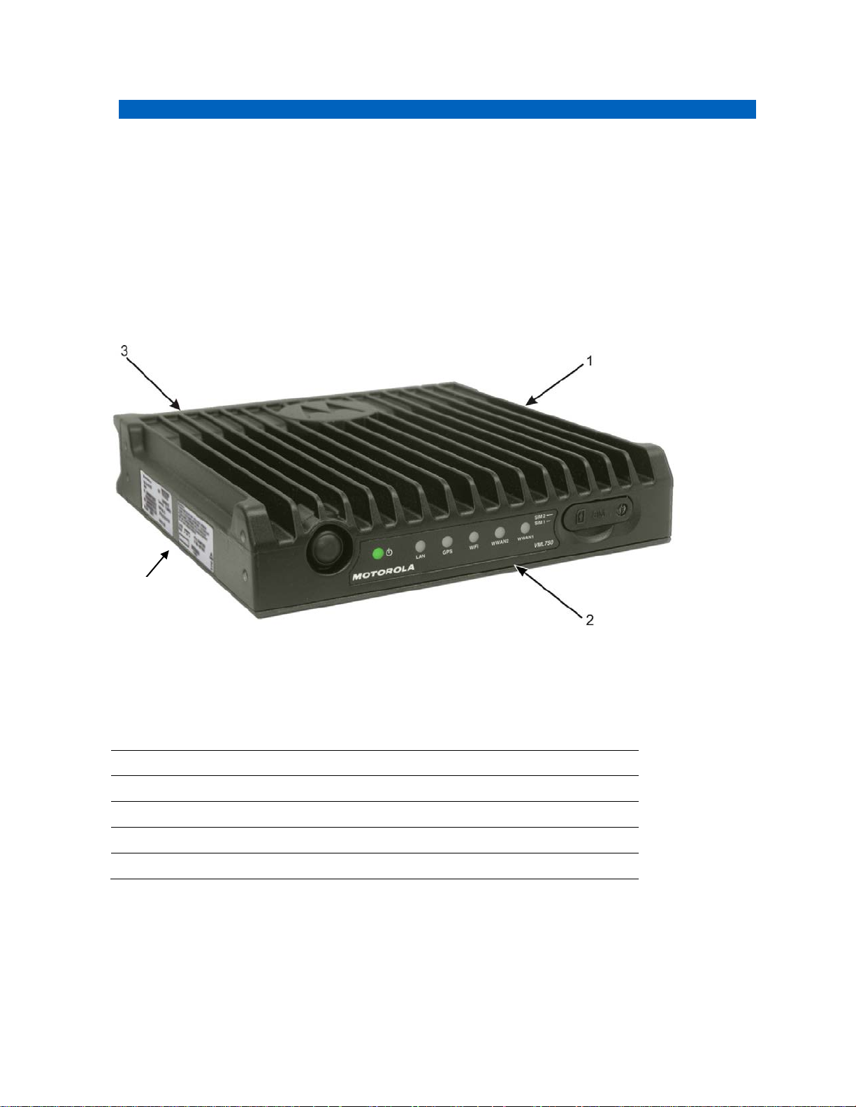
Item #
Description
1.
Modem
2.
Front Panel
3.
Connector Panel (Back Panel - not shown)
4.
CRYPTR Card Door (not shown)
4
Chapter 1
VML750 Description
Designed for the harsh environments of public safety vehicles, the VML750 LTE Vehicular Subscriber
Modem (VSM) is a solid-state device capable of withstanding vibration, humidity, temperature extremes,
and other challenges encountered in the field. Mounted in the trunk or passenger compartment, it
provides broadband, wide-area network connectivity to devices in and around the vehicle.
Figure 1 VML750 General View
Table 1 Legend for General View
3

4
6802988C54-D
Chapter 1: VML750 Description
Send Feedback
VML750 Models
The Motorola VML750 LTE Vehicular Subscriber Modem (VSM) is a power class 3 device.
The VML750 model F0025 includes the following sub-models:
-
FLN1057A: A multi-m ode modem that operates in LTE Bands 14/13 and 3G EvDo BC0/BC1.
The modem supports WiFi as client and AP as well as GPS for location and support for data
encryption (CyrptR).
-
FLN2057A: A multi-mode modem that operates in LTE Bands 17/14/13/5/4/2 (Band 13 is
hardware ready only) and EvDo BC0/BC1 UMTS B5/B2 GSM. The modem supports WiFi as
client and AP as well as GPS for location and support for data encryption (CyrptR).
-
FLN5057A: A multi-mode modem that operates in LTE Bands 1, 3, 5, 7 ,8, 28 and UMTS bands
1 and 5. The modem supports WiFi as client and AP as well as GPS for location and support for
data encryption (CyrptR).
-
FLN5058A: A multi-mode modem that operates in LTE Bands 3, 7 and 20 and UMTS bands 1
and 8. The modem supports WiFi as client and AP as well as GPS for location and support for
data encryption (CyrptR).
-
FLN5059A: A multi-mode modem that operates in LTE Bands 2, 4 ,7 ,28 and 7 and UMTS
bands 2, 4 and 5. The modem supports WiFi as client and AP as well as GPS for location and
support for data encryption (CyrptR).
6802988C54-D
Chapter 1: VML750 Description
Send Feedback
Item #
Item
Description
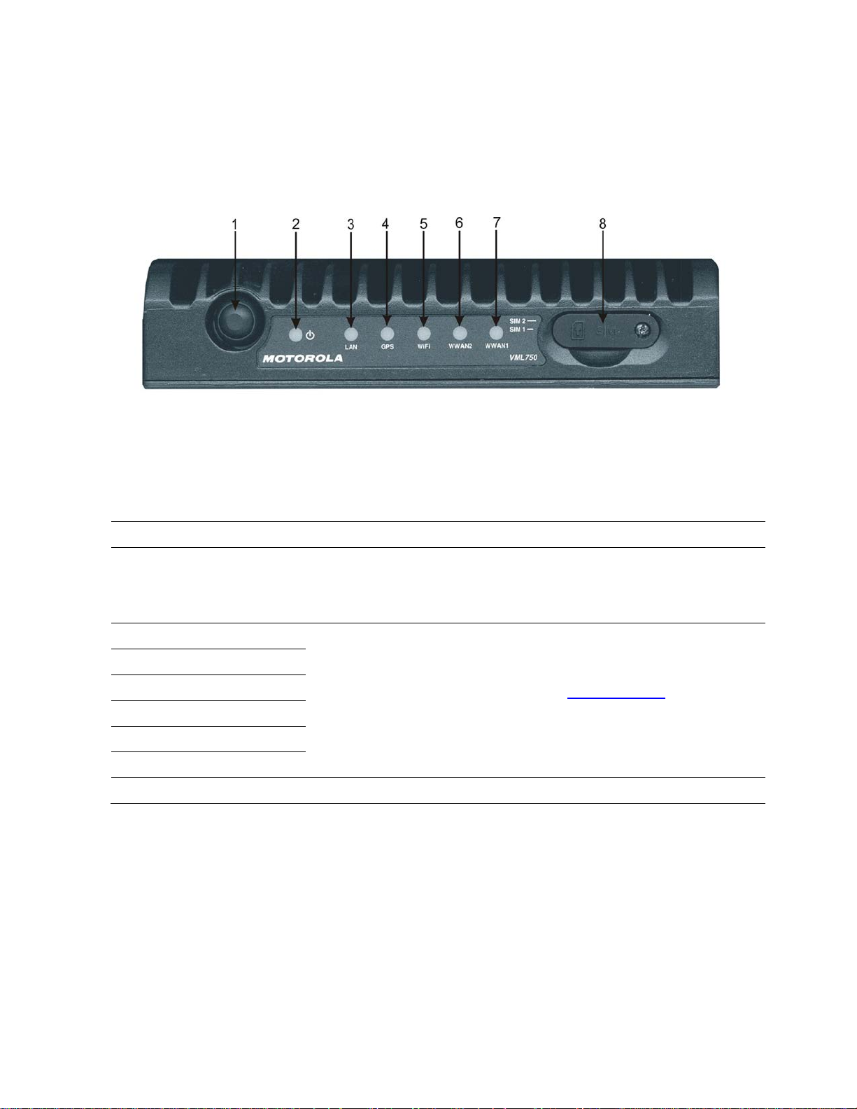
ignition switch to On. This button is also used to apply factory reset.
2.
Power LED
3.
LAN LED
4.
GPS LED
For LED indications, refer to LED Indications
5.
WiFi LED
6.
WWAN2 LED
7.
WWAN1 LED
8.
SIM Card Door
Access door to VML750 SIM
Figure 2 Front Panel
VML750 Front Panel
The VML750 Vehicular Subscriber Modem (VSM) Front Panel is shown in the following figure.
Table 2 Legend for Front Panel
1. Power Button* The power button is used to turn the VML750 LTE Vehicular
Subscriber Modem (VSM) on or off when Ignition Sense is disabled.
If the Ignition Sense is enabled, you also need to turn the vehicle
5

6
6802988C54-D
Chapter 1: VML750 Description
Send Feedback
Figure 3 Back Panel
VML750 Back Panel
The VML750 Back Panel is shown in the following figure.
Table 3 Legend for Back Panel
Item # Description
1
2
3
4
5
6
7
8
RF SMA female type connector (WWAN1 DIV/WiFi)
RF SMA female type connector (WWAN1 MAIN1)
RF SMA female type connector ( WWAN2 DIV)
RF SMA female type connector (WWAN2 MAIN2)
RF SMA female type connector (GPS)
LAN/Ethernet communication connector (RJ45)
Micro AB type connector (USB 2.0)
DC power and GPIO D-type, 9–pin connector
 Loading...