

Page 1

PUBLIC SAFETY LTE
VML750 - LTE VEHICULAR
SUBSCRIBER MODEM (VSM)
INSTALLATION GUIDE
@6802988C54@
6802988C54-C
January 2015
© 2015 Motorola Solutions, Inc. All rights reserved.
Page 2

Copyrights
TheMotorolaproductsdescribedinthisdocumentmayincludecopyrightedMotorolacomputerprograms.LawsintheUnitedStatesandothercountries
preserveforMotorolacertainexclusiverightsforcopyrightedcomputerprograms.Accordingly,anycopyrightedMotorolacomputerprogramscontainedin
theMotorolaproductsdescribedinthisdocumentmaynotbecopiedorreproducedinanymannerwithouttheexpresswrittenpermissionofMotorola.
©2015MotorolaSolutions,Inc.AllRightsReserved
Nopartofthisdocumentmaybereproduced,transmitted,storedinaretrievalsystem,ortranslatedintoanylanguageorcomputerlanguage,inanyformorby
anymeans,withoutthepriorwrittenpermissionofMotorolaSolutions,Inc.
Furthermore,thepurchaseofMotorolaproductsshallnotbedeemedtogranteitherdirectlyorbyimplication,estoppelorotherwise,anylicenseunderthe
copyrights,patentsorpatentapplicationsofMotorola,exceptforthenormalnonexclusive,royalty-freelicensetousethatarisesbyoperationoflawinthesale
ofaproduct.
Disclaimer
Pleasenotethatcertainfeatures,facilities,andcapabilitiesdescribedinthisdocumentmaynotbeapplicabletoorlicensedforuseonaparticularsystem,or
maybedependentuponthecharacteristicsofaparticularmobilesubscriberunitorcongurationofcertainparameters.PleaserefertoyourMotorolacontact
forfurtherinformation.
Trademarks
MOTOROLA,MOTO,MOTOROLASOLUTIONS,andtheStylizedMLogoaretrademarksorregisteredtrademarksofMotorolaTrademarkHoldings,LLC
andareusedunderlicense.Allothertrademarksarethepropertyoftheirrespectiveowners.
EuropeanUnion(EU)WasteofElectricalandElectronicEquipment(WEEE)directive
TheEuropeanUnion'sWEEEdirectiverequiresthatproductssoldintoEUcountriesmusthavethecrossedouttrashbinlabelontheproduct(orthepackage
insomecases).
AsdenedbytheWEEEdirective,thiscross-outtrashbinlabelmeansthatcustomersandend-usersinEUcountriesshouldnotdisposeofelectronicand
electricalequipmentoraccessoriesinhouseholdwaste.
Customersorend-usersinEUcountriesshouldcontacttheirlocalequipmentsupplierrepresentativeorservicecentreforinformationaboutthewastecollection
systemintheircountry.
Page 3

DocumentHistory
■■■■■■■■■■■■■■■■■■■■■■■■■■■■■■■■■■■■■■■■■■■■
EditionDescriptionDate
Release1.0FirstreleaseofVML750—LTEV ehicularSubscriber
Modem(VSM)InstallationGuide.
Release2.0SecondreleaseofVML750—L TEV ehicularSubscriber
Modem(VSM)InstallationGuide.
Release3.0ThirdreleaseofVML750—LTEV ehicularSubscriber
Modem(VSM)InstallationGuide.
Document
History
■
■
■
■
April2014
July2014
January2015
6802988C54-CJanuary2015i
Page 4

VML750—L TEV ehicularSubscriberModem(VSM)InstallationGuide
Thispageintentionallyleftblank.
ii 6802988C54-C January 2015
Page 5

Contents
■■■■■■■■■■■■■■■■■■■■■■■■■■■■■■■■■■■■■■■■■■■■
■
■
■
■
VML750—L TEVehicularSubscriberModem(VSM)InstallationGuide
NotationalConventions......................................-xii
RequiredDocumentsforcompleteVSMDeployment........................-xiii
MotorolaSolutionsSupportCenter.................................-xiv
SupportCenter........................................-xiv
NorthAmericaPartsOrganization...............................-xiv
Safety..............................................-xiv
FCCInterference.........................................-xv
LegalNotice...........................................-xv
Table
of
Contents
Chapter1:VML750Description
TheVML750Unit........................................1-1
Modem..............................................1-2
ConnectorPanel..........................................1-3
ConnectorPanelforB20LTEOnlyConguration..........................1-4
LEDIndicatorPanelwithPowerButtonandSIMCardDoor.....................1-5
PowerButton...........................................1-5
SIMCard.............................................1-6
Chapter2:VML750Installation
UnpackingandInspectingtheShipment..............................2-1
SafetyandGeneralInformation..................................2-1
PlanningtheInstallation......................................2-3
InstallationConstraints....................................2-3
CablesRouting........................................2-5
DrillingHoles........................................2-5
ToolsandEquipment.....................................2-5
Antennas.............................................2-6
AntennasforL TEPublicandPrivateNetworks.........................2-6
AntennaCongurationforLTEPublicNetwork.......................2-6
AdditionalAntennaforCongurationSupportingL TEPrivateNetworkonWW AN1.....2-7
AntennasforB20LTEonlyConguration...........................2-8
MainAntenna......................................2-8
DiversityAntenna....................................2-9
Cables..............................................2-9
MountingBrackets........................................2-11
ModemInstallationProcess....................................2-12
AntennaMounting........................................2-12
SpecialAntennasInstallationConsiderations..........................2-13
6802988C54-BJuly2014iii
Page 6

VML750—L TEV ehicularSubscriberModem(VSM)InstallationGuide
GeneralAntennaInstallationSafetyConsiderations.....................2-13
MainAntenna......................................2-13
ModemInstallationProcedure...................................2-14
CablesRoutingandConnectionProcedure.............................2-15
DCPowerandIgnitionCableInstallation............................2-15
AntennaCablesInstallationforPublicandPrivateNetworkCongurations............2-17
AntennaCablesInstallationforB20L TEOnlyConguration..................2-18
LAN/EthernetCableInstallation................................2-19
MicroUSBCableInstallation.................................2-19
SIMInstallation..........................................2-20
CryptRCardRemovalandInstallation...............................2-21
CapInstallation..........................................2-24
PoweringtheModemUp.....................................2-24
Chapter3:TroubleshootingtheVML750
Troubleshooting..........................................3-2
LEDIndicatorsFunctions.....................................3-5
Chapter4:UsingtheVML750
General..............................................4-1
AppendixA:Specications
Physical.............................................A-1
CommunicationPorts.....................................A-1
RFPorts...........................................A-1
PowerPort..........................................A-2
LEDs.............................................A-2
OperatingTemperature....................................A-2
Power............................................A-2
RFCharacteristics.......................................A-2
AppendixB:Reference
ReplacementParts.........................................B-1
ReplacementPartsList....................................B-1
KitReplacementPartsList...................................B-2
ApprovedAntennasandCablesReplacementsList.......................B-2
AppendixC:LTE&LMRAntennasMountingRecommendations
PolicePatrolV ehicleAntennasLocationConsiderations—Overview.................C-1
PlanningAntennaMountingLocationonaPolicePatrolV ehicle...................C-2
iv6802988C54-BJuly2014
Page 7

ListofFigures
■■■■■■■■■■■■■■■■■■■■■■■■■■■■■■■■■■■■■■■■■■■■
■
■
■
■
Figure1-1:VML750-GeneralView................................1-2
Figure1-2:ConnectorPanel....................................1-3
Figure1-3:ConnectorPanel....................................1-4
Figure1-4:LEDIndicatorsPanel..................................1-5
Figure2-1:VML750-SchematicCarInstallation..........................2-4
Figure2-2:VML750-Dimensions.................................2-4
Figure2-3:AntennaforLTEPublicNetworkonWW AN2......................2-6
Figure2-4:AntennaforWiFiandGPS...............................2-7
Figure2-5:AntennaforCongurationSupportingL TEPrivateNetwork...............2-8
Figure2-6:MainAntenna.....................................2-8
Figure2-7:DiversityAntenna-StandardConguration.......................2-9
Figure2-8:A vailableCables....................................2-10
Figure2-9:BracketDimensions..................................2-11
Figure2-10:MountingBrackets..................................2-14
Figure2-11:DCPowerandIgnitionCableRoutingIntoEngineCompartment.............2-15
FigureC-1:PolicePatrolV ehicle—AntennasLocationSuggestion.................C-2
List
of
Figures
6802988C54-BJuly2014v
Page 8

ListofFigures
Thispageintentionallyleftblank.
vi6802988C54-BJuly2014
Page 9

ListofTables
■■■■■■■■■■■■■■■■■■■■■■■■■■■■■■■■■■■■■■■■■■■■
■
■
■
■
Table3-1:TroubleshootingtheVML750..............................3-2
Table3-2:LEDIndicatorsFunctions................................3-5
List
of
Tables
6802988C54-BJuly2014vii
Page 10

ListofTables
Thispageintentionallyleftblank.
viii6802988C54-BJuly2014
Page 11

ListofProcedures
■■■■■■■■■■■■■■■■■■■■■■■■■■■■■■■■■■■■■■■■■■■■
■
■
■
■
Procedure2-1:HowtoMounttheAntennas.............................2-13
Procedure2-2:HowtoInstalltheModemonaFlatSurface.....................2-14
Procedure2-3:HowtoInstalltheDCPowerandIgnitionCable...................2-15
Procedure2-4:HowtoInstallAntennaCablesforPublicNetwork..................2-17
Procedure2-5:HowtoCompletetheAntennaInstallationforPrivateNetwork............2-18
Procedure2-6:HowtoInstallAntennaCables............................2-18
Procedure2-7:HowtoInstalltheLAN/EthernetCable........................2-19
Procedure2-8:HowtoInstalltheMicroUSBCable.........................2-19
Procedure2-9:HowtoInstallaSIMCard..............................2-20
Procedure2-10:HowtoRemovetheCryptRCard..........................2-21
Procedure2-11:HowtoInstalltheCryptRCard...........................2-23
Procedure2-12:HowtoInstallCap(s)onUnusedConnector(s)...................2-24
Procedure2-13:HowtoPoweruptheModem...........................2-24
ProcedureC-1:PlanningAntennasLocationonaPolicePatrolV ehicle................C-2
List
of
Procedures
6802988C54-BJuly2014ix
Page 12

ListofProcedures
Thispageintentionallyleftblank.
x6802988C54-BJuly2014
Page 13

VML750—LTEVehicularSubscriber
Modem(VSM)InstallationGuide
■■■■■■■■■■■■■■■■■■■■■■■■■■■■■■■■■■■■■■■■■■■■
WhatIsCoveredInThisManual?
TheVML750LTEVSMInstallationGuideprovidesgeneralinstructionsforinstalling,
operating,andtroubleshootingtheVML750.
About
This
Manual
■
■
■
■
Thisguideincludesthefollowingcongurations:
•F0025(VML750)model-
◦FLN1057submodel—LTEB14+VzW.
◦FLN2
◦FLN1310submodel—L TE B20.
057(Future option) submodel—L TEB14+VzW+A T&T.
6802988C54-BJuly2014xi
Page 14

NotationalConventions
Theguideisorganizedasfollows:
•Chapter1,"VML750Description"providestheproductoverview .
•Chapter2,"VML750Installation"providesunpackinginstructionsandall
requiredproceduresforinstallingtheVML750.
•Chapter3,"TroubleshootingtheVML750"providesdetailsregardingpossible
malfunctionsthatmayoccurafterrst-timeinstallationoftheVML750,their
probablecause,andtherecommendedcorrectiveactions.
•Chapter4,"UsingtheVML750"providesgeneralinformationregardingtheuseoftheVML750.
•AppendixA,"Specications"providestheVML750modemspecications.
•AppendixB,"Reference"providespartnumbersinformationforthemodemandantennas.
NotationalConventions
■■■■■■■■■■■■■■■■■■■■■■■■■■■■■■■■■■■■■■■■■■■■
Thefollowingconventionsareusedinthisdocument:
•Italicsareusedtohighlightthefollowing:
◦Chaptersandsectionsinthisandrelateddocuments
◦Dialogbox,windowandscreennames
◦Drop-downlistandlistboxnames
◦Checkboxandradiobuttonnames
•Boldtextisusedtohighlightthefollowing:
◦Keynamesonakeypad
◦Buttonnamesonascreen
•bullets(•)indicate:
◦Actionitems
◦Listsofalternatives
◦Listsofrequiredstepsthatarenotnecessarilysequential
■
■
•Sequentiallists(e.g.,thosethatdescribestep-by-stepprocedures)appearasnumberedlists.
xii6802988C54-BJuly2014
Page 15

VML750—LTEVehicularSubscriberModem(VSM)InstallationGuideRequiredDocumentsforcompleteVSMDeployment
RequiredDocumentsforcompleteVSMDeployment
■■■■■■■■■■■■■■■■■■■■■■■■■■■■■■■■■■■■■■■■■■■■
■
■
Tocompletethefulldeploymentofthemodem,youmayneedthefollowingdocuments:
•InformationrelatedtoVML750congurationintheVML750CongurationGuideP/N
6802988C55locatedat:https://businessonline.motorolasolutions.com
•InformationrelatedtoVML750monitoringcanbefoundintheVML750LTEVehicle
SubscriberModem(VSM)StatusUtilityQuickReferenceGuideP/N6802988C79.
•InformationrelatedtothedevicelicensingcanbefoundintheDeviceLicensingQuick
ReferenceGuideP/N6871024P25locatedat:https://businessonline.motorolasolutions.com
6802988C54-BJuly2014xiii
Page 16

MotorolaSolutionsSupportCenter
MotorolaSolutionsSupportCenter
■■■■■■■■■■■■■■■■■■■■■■■■■■■■■■■■■■■■■■■■■■■■
SupportCenter
TheMotorolaSolutionsSupportCenter(SSC)istheprimaryMotorolaSolutionssupportcontact.Call:
•Priortoanysoftwarereload.
•ToconrmtroubleshootingresultsandanalysispriortoremovingandreplacingaField
ReplaceableUnit(FRU)andFieldReplaceableEntity(FRE)torepairthesystem.
For...Phone
Domesticcalls
Internationalcalls
800–221–7144
302–444–9800
■
■
NorthAmericaPartsOrganization
Forassistanceinorderingreplacementpartsoridentifyingapartnumber,contactMotorola'sparts
organization.
PleaserememberthatyourrstresponsewhentroubleshootingyoursystemistocalltheMotorolaSSC.
For...Phone
PhoneOrders800–422–4210(USandCanadaorders)
302-444-9842(Internationalorders)
FaxOrders800–622–6210(USandCanadaorders)
Helpidentifyinganitemorpartnumber800–422–4210andselectchoice3fromthemenu.
Safety
■■■■■■■■■■■■■■■■■■■■■■■■■■■■■■■■■■■■■■■■■■■■
Beforeinstalling/usingthisproduct,theinstaller/operatormustbefamiliarwiththeRFenergy
awarenessinformationandoperatinginstructionsinthe“ProductSafetyandRFEnergyExposure
BookletforMobileTwo-WayRadiosInstalledinV ehiclesorasFixedSiteControlStations”
enclosedwiththeVML750L TEVSM(MotorolaPublicationpartnumber6881095C99)toensure
compliancewithRadioFrequency(RF)energyexposurelimits.
■
■
xiv6802988C54-BJuly2014
Page 17

VML750—LTEVehicularSubscriberModem(VSM)InstallationGuideFCCInterference
FCCInterference
■■■■■■■■■■■■■■■■■■■■■■■■■■■■■■■■■■■■■■■■■■■■
■
■
TheVML750 isgranted with two separate FCCIDs; for baseline models: FLN0058andFLN2058.
These FCC IDs are only given forFCCcomplianceand notforsale purposes.
ThisdevicecomplieswithPart15oftheFCCRules.Operationissubjecttothefollowingtwoconditions:
•Thisdevicemaynotcauseharmfulinterference.
•Thisdevicemustacceptanyinterferencereceived,includinginterference
thatmaycauseundesiredoperation.
Changesormodicationsmadetothisproduct,notexpresslyapprovedbyMotorola,will
voidtheuser'sauthoritytooperatetheequipment,perFCCRulePart15.21.
LegalNotice
■■■■■■■■■■■■■■■■■■■■■■■■■■■■■■■■■■■■■■■■■■■■
TheVML750OSSlegalnoticewillbeprovidedbyMotorolaperrequest.
■
■
6802988C54-BJuly2014xv
Page 18

LegalNotice
Thispageintentionallyleftblank.
xvi6802988C54-BJuly2014
Page 19

VML750Description
■■■■■■■■■■■■■■■■■■■■■■■■■■■■■■■■■■■■■■■■■■■■
TheVML750Unit
■■■■■■■■■■■■■■■■■■■■■■■■■■■■■■■■■■■■■■■■■■■■
Chapter
1
■
■
■
■
■
■
TheMotorolaVML750-LTEV ehicularSubscriberModem(VSM)isapowerclass3device.
ThefollowingmodelsandtheirSKUareavailable:
•F0025family:
◦FLN1057:Amulti-modemodemthathastheabilitytooperateinLTEBand14/13
and3GEvDoBC0/BC1.ThemodemsupportsWiFiasclientandAPaswellas
GPSforlocationandsupportfordataencryption(CyrptR).
FLN2057 (Future option): Amulti-modemodemthathastheabilitytooperate
◦
inLTEBand 17/14/13/5/4/2,andEvDoBC0/BC1UMTSB5/B2GSM.Themodem
supportsWiFias clientandAPaswellasGPSforlocationandsupportfordata
encryption(CyrptR).
◦FLN1310:Amulti-modemodemthathastheabilitytooperateinL TE
Band20.ThemodemsupportsWiFiasclientandAPaswellasGPSfor
locationandsupportfordataencryption(CyrptR).
SeeFigure1-1.
6802988C54-BJuly20141-1
Page 20
ModemChapter1:VML750Description
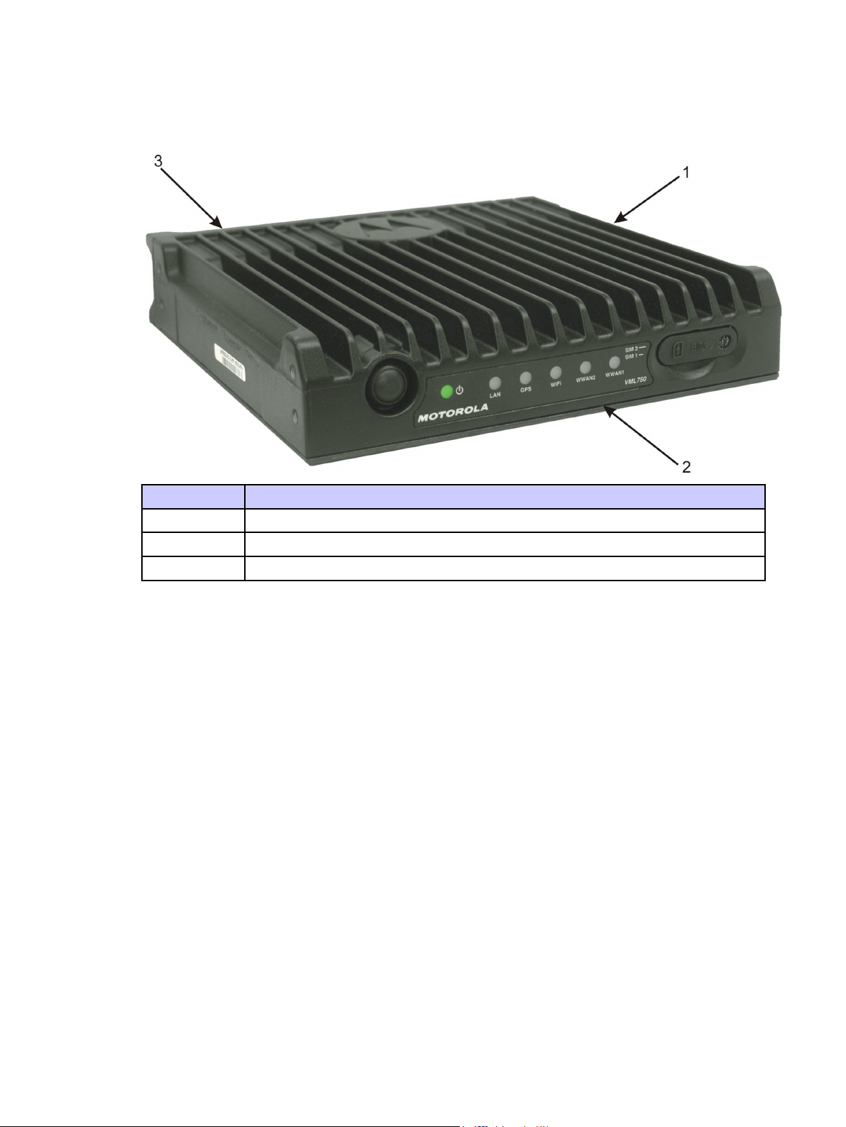
Figure1-1VML750-GeneralView
Item#Description
1
2
3
Modem
LEDIndicatorPanel(FrontPanel)
ConnectorPanel(BackPanel-notshown)
FordetailedspecicationsoftheVML750unit,seeAppendixA,"Specications".
Modem
■■■■■■■■■■■■■■■■■■■■■■■■■■■■■■■■■■■■■■■■■■■■
Themodemhasaconnectorpanel(backpanel)andaLEDIndicatorpanelwithaPowerbutton(frontpanel).
■
■
1-26802988C54-BJuly2014
Page 21
VML750—LTEVehicularSubscriberModem(VSM)InstallationGuideConnectorPanel
ConnectorPanel
■■■■■■■■■■■■■■■■■■■■■■■■■■■■■■■■■■■■■■■■■■■■
■
■
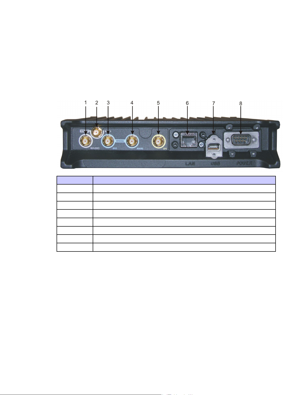
TheVML750Connectorpanelconsistsofthefollowing(seeFigure1-2):
Figure1-2ConnectorPanel
Item#Description
1
2
3
4
5
6
7
8
RFSMAfemaletypeconnector(WW AN1DIV/WiFi)
RFSMAfemaletypeconnector(WWAN1main)
RFSMAfemaletypeconnector(WWAN2DIV)
RFSMAfemaletypeconnector(WWAN2main)
RFSMAfemaletypeconnector(GPS)
LAN/Ethernetcommunicationconnector(RJ45)
MicroABtypeconnector(USB2.0)
DCpowerandGPIOD-type,9–pinconnector
6802988C54-BJuly20141-3
Page 22

ConnectorPanelforB20LTEOnlyCongurationChapter1:VML750Description
ConnectorPanelforB20LTEOnlyConguration
■■■■■■■■■■■■■■■■■■■■■■■■■■■■■■■■■■■■■■■■■■■■
■
■
TheVML750Connectorpanelconsistsofthefollowing(seeFigure1-3):
Figure1-3ConnectorPanel
Item#Description
1
2
3
4
5
6
7
8
RFSMAfemaletypeconnector(WW AN2DIV/WiFi)
RFSMAfemaletypeconnector(WWAN2main)
RFSMAfemaletypeconnector(WWAN1DIV1)(doesnotapplyforB20LTEonly
conguration)
RFSMAfemaletypeconnector(WW AN1MAIN1)(doesnotapplyforB20L TEonly
conguration)
RFSMAfemaletypeconnector(GPS)
LAN/Ethernetcommunicationconnector(RJ45)
MicroABtypeconnector(USB2.0)
DCpowerD-type,9–pinconnector
1-46802988C54-BJuly2014
Page 23

VML750—LTEVehicularSubscriberModem(VSM)InstallationGuideLEDIndicatorPanelwithPowerButtonandSIMCardDoor
LEDIndicatorPanelwithPowerButtonandSIMCardDoor
■■■■■■■■■■■■■■■■■■■■■■■■■■■■■■■■■■■■■■■■■■■■
■
■
AsetofsixLEDsisusedfordiagnosticsandtestingoftheunit(seeFigure1-4).
Figure1-4LEDIndicatorsPanel
Item#Description
1
2
PowerButton
PowerIndicator
3LAN
4GPS
5
WiFi
6WWAN2
7
8
WWAN1(doesnotapplyforB20L TEonlyconguration)
SIMCardDoor
PowerButton
■■■■■■■■■■■■■■■■■■■■■■■■■■■■■■■■■■■■■■■■■■■■
■
■
ThePowerbuttonisusedtoturntheVML750OnorOffwhenIgnitionSenseisdisabled.IftheIgnitionSenseis
enabled,youalsoneedtoturnyourvehicleignitionswitchtoOn.Thisbuttonisalsousedtoapplyfactoryreset.
6802988C54-BJuly20141-5
Page 24

SIMCardChapter1:VML750Description
SIMCard
■■■■■■■■■■■■■■■■■■■■■■■■■■■■■■■■■■■■■■■■■■■■
■
■
IfyourLTEmodemisintendedtohomeonyourprivateMotorolaL TEnetwork,youareprovidedwitha
MotorolaLTESIMcard(tobeinsertedintoSIM1slot).IfyourL TEmodemisintendedtohomeonapublic
carrierLTEnetwork,youneedtoobtainaSIMcardfromthatpubliccarrierandinsertintoSIM2slot.The
SIMcardmustbeinsertedwiththemetalleadsfacingdownandthenotchedcornerontheleft.
TheWiFimodemisstilloperationalwithoutaSIMcard.
•WiFimustbeconguredpriortouse.RefertoVML750CongurationGuide(6802988C55)
locatedinhttps://businessonline.motorolasolutions.com forcongurationprocedure.
1-66802988C54-BJuly2014
Page 25

VML750Installation
■■■■■■■■■■■■■■■■■■■■■■■■■■■■■■■■■■■■■■■■■■■■
UnpackingandInspectingtheShipment
■■■■■■■■■■■■■■■■■■■■■■■■■■■■■■■■■■■■■■■■■■■■
Chapter
2
■
■
■
■
■
■
Unpackyourequipmentandcheckthecontentstoensurethatyouhavereceivedallthespecieditems.
Thoroughlyinspecttheequipmentforshippingdamageassoonaspossibleafterdelivery.Reportany
damageyoundtoyourMotorolaCustomerServicerepresentativeimmediately.
SafetyandGeneralInformation
■■■■■■■■■■■■■■■■■■■■■■■■■■■■■■■■■■■■■■■■■■■■
AproperlyinstalledVML750unitminimizesservicecalls.WhenmountingtheVML750
unitcomponents,considerthefollowingfactors:
ThisdevicerequiresprofessionalinstallationtosatisfycompliancewithFCCrequirements.
•Themountingsurfacemusthavesufcientstrengthtosupporttheequipmentbeing
mountedandtopreventitfrombecominglooseovertime.
■
■
•Donotattachcomponentstoanypartofthevehiclesubjectedtoexcessivevibration.
•DonotmounttheVML750unitonaatsurfacewheretheunitcould
becomepartiallysubmersedinwater.
•Theproposedlocationoftheequipmentbeingmountedorwires/cablesattached
mustnotinterferewithdriver/passengerseatingorlegspace.
6802988C54-BJuly20142-1
Page 26

SafetyandGeneralInformationChapter2:VML750Installation
•Selectalocationsuchthatheatfromtheunitdoesnotdamageanywiringorany
otherplasticorheat-sensitivepartsoftheautomobile.
•Usethesuppliedmountinghardware.
•LeavesufcientspacearoundtheVML750unitforairowandinstallation.
•Selectalocationthatpermitsroutingthecablesasdirectlyaspossible.
•Ensurethatthecablesarenotstretched,andnotsubjecttoheatfromtheengine,
transmissionhousing,orheatingducts.
•Crimpconnectorssecurely.
•Donotruncablesoversharpedgesthatmaycauseexcessivewearor
chafngofthecableinsulation.
•Donotinstallcomponentsinlocationswheretheymaycauseinterference
totheoperationofthevehicle'scontrols.
•Onlyqualiedpersonnelmayinstallcommunicationequipment.
•Ensuresecuretighteningofcableconnectors.
Installthisproductinavehicleinaccordancewiththevehiclemanufacturer’sguidelinesandthe
instructionsdetailedinthismanual.UseonlytheMotorolapartsspeciedinthismanual.
Checktherequiredmountinglocations.Itmightbenecessarytopenetratetherewalltoreachthebattery.
Beforedrillingcommences,ensurecableclearanceontheoppositesideoftherewallanddonotinstall
thevehicle’sElectronicControlModules(ECM’s)ontheoppositesideoftherewall.Protectthecable
whereitpassesthroughtherewallbyusingagrommetorsimilarprotectivemeasures.
InstallingtheVML750attheendofthevehicleabovetheexhaust
pipemaycausetheVML750tooverheat.
VEHICLESEQUIPPEDWITHAIRBAGS
Anairbaginateswithgreatforce.DONOTplaceobjects,including
communicationsequipment,intheareaovertheairbagorintheairbag
deploymentarea.Ifthecommunicationequipmentisimproperlyinstalled
andtheairbaginates,thiscouldcauseseriousinjury.
Ifnecessary,contactthevehiclemanufacturerforairbaginformationspecictothevehicle.
Verifythatnoneofthevehicle’ssystemsareaffectedbyuseofthe
unit,e.g.cruisecontrol,ABSbreaking,tractioncontrol,engine
management,directionindicators,lights,etc.
2-26802988C54-BJuly2014
Page 27

VML750—LTEVehicularSubscriberModem(VSM)InstallationGuidePlanningtheInstallation
Useexistingopeningsthroughtherewalltoavoiddrilling.Ifdrilling
isamust,verifynottodamagetheVehicleElectronicControlModules
(ECM’s),fuellines,brakelines,and/orcablelooms.
Forvehiclesequippedwithelectronicbrakingsystems,see“ANTI-SKIDBRAKING
PRECAUTIONS”,Motorolapublication68P81 109E34.
Itismandatorythatmodemsinstalledinvehiclesfuelledbyliqueedpetroleum
gasconformtotheNationalFireProtectionAssociationstandardNFP A58,which
appliestovehicleswithaliquidpropane(LP)gascontainerinthetrunkorother
sealedoffspacewithintheinteriorofthevehicle.TheNFPA58requiresthe
following:
(1)ThespaceinwhichtheLPgascontaineranditsttingsarelocatedmustbe
isolatedbyasealfromthespacecontainingmodemequipment.
(2)Removable(outside)llingconnectionsshallbeused.
(3)Thecontainerspaceshallbeventedtotheoutside.
PlanningtheInstallation
■■■■■■■■■■■■■■■■■■■■■■■■■■■■■■■■■■■■■■■■■■■■
Planningisthekeytofast,easyandsafeinstallation.
Takethefollowingpointsintoconsiderationwhenselectingalocationandplanningtheinstallation.
InstallationConstraints
RefertotheSafetyInstructionsin“ProductSafetyandRFEnergyExposureBookletforMobileTwo-Way
RadiosInstalledinVehiclesorasFixedSiteControlStations”P/N6881095C99.
TheVML750mustbeinstalledinthecar’strunk,ontheoororthesidewalls
(coolingnsfacingup,ortotheside).
■
■
6802988C54-BJuly20142-3
Page 28

InstallationConstraintsChapter2:VML750Installation
TheVML750mustnotbeinstalledwiththecoolingnsfacingdown.Failuretocomply
maycauseoverheatingproblemsandperformancedegradation.
Figure2-1showsaschematicVML750installationinacar.
Figure2-1VML750-SchematicCarInstallation
Beforebeginningtheinstallationprocessmakesurethatthespaceavailableattheinstallation
siteisadequateforthemodemanditsaccessories.Eachinstallationcongurationrequiresa
differentareaformountingthemodemwithoutobstruction.
Whenchoosingalocation,ensureeasyinstallationandreplacementoftheunit.
Figure2-2givestheVML750dimensions.
Figure2-2VML750-Dimensions
2-46802988C54-BJuly2014
Page 29

VML750—LTEVehicularSubscriberModem(VSM)InstallationGuideCablesRouting
CablesRouting
•Beforerunningawireordrillingahole,inspectthevehicleanddeterminehowandwhere
youintendtomounttheantenna,modem,andtheinput/outputdevice.
•Planwireandcableroutingtoprovidemaximumprotectionfromoverheating,
batteryacid,movingpartsandsharpedges.
•Keepcablesawayfromignitioncircuitstoreducenoisepickupintheradioequipment.
•Verifythatthecablesareofsufcientlength.Donotconnecttwoshortlengthswith
asplice;doingsoresultsinpowerloss.Refrainfromlooseexcessinthecables,
butleaveenoughslacktoallowre-connectionifnecessary.
•Donotruncablesexternallyorunderneathoormats.
•Donotlocatecableswherethedriverorpassengerscankickthemorwherethey
caninterferewithoperationofthedriver’sfootpedals.
•Whenroutingthecables,refrainfromcreatingsharpbendsorkinks.
DrillingHoles
ToolsandEquipment
Fordetailedantennacablesroutinginstructions,refertotheInstallation
Guidesuppliedwitheachantenna.
•Wherepossible,useexistingholesintherewall,thetrunkwallandthe
channelsaboveorbeneaththedoors.
•Ifyoumustdrillholes,verifynottodamageotherwiring,breaklinesorfuellines.
•Whendrillingaholeintheroof,takecarenottosnagtheroofliner.
•Topreventrustingafterdrilling,removeallmetalburrsandresidue,andcompletely
cleantheareatoensuretheremovalofallsteeldust.
•Insertrubbergrommetsinalldrilledholestoprotectcables,exceptforantennascables.
•#2Phillipsscrewdriver
•Electricdrillanddrillbitset
•X-actoknifeorequivalent
•Wirestrippers
•Longnosepliers
•Smallsidecutters
•Crimpingtool
6802988C54-BJuly20142-5
Page 30

AntennasChapter2:VML750Installation
•Wrenchset,including8mmfortraytounitattachment
•Crescentwrench
•Spannerwrench
•3mmAllenwrenchsetforunittotrayattachment
•No.8Torxscrewdriver
•Electricaltape
Antennas
■■■■■■■■■■■■■■■■■■■■■■■■■■■■■■■■■■■■■■■■■■■■
■
■
ThefollowingantennasdescribedareforvariousVSMfamilyproducts.
AntennasforLTEPublicandPrivateNetworks
AntennaCongurationforLTEPublicNetwork
TheantennaisusedtoenhancethereceptioncapabilityinpoorreceptionareasandalsotosupportMultiple
InputMultipleOutput(MIMO)modesforLTE.
Twoidenticalantennasareused;oneforWW AN2MainandoneforWW AN2div .
Theantennascanbeprovidedwith12ftor17ftcoaxialcable.
Figure2-3AntennaforLTEPublicNetworkonWWAN2
TocompletethepublicnetworkinstallationthefollowingantennaisusedforWiFiconnectivityonWW AN1
WiFi/DivandGPSreception.
Theantennaisconstructedofthreeantennas:
•Internalantenna-forWiFi(tobeconnectedtoWW AN1diversity)
2-66802988C54-BJuly2014
Page 31

VML750—LTEVehicularSubscriberModem(VSM)InstallationGuideAdditional
AntennaforCongurationSupportingL TEPrivateNetworkonWW AN1
•GPSactiveantenna(tobeconnectedtoGPSport)
•ExternalWhip—formain(tobeconnectedtoWW AN1main).Y oumay
installitforprivatenetworkuse.
TheantennaisshowninFigure2-4.
Figure2-4AntennaforWiFiandGPS
AdditionalAntennaforCongurationSupportingLTEPrivateNetworkonWWAN1
Forthisaddition,theExternalWhipisinstalled.
Theantennacanbeprovidedwith12ftor17ftcoaxialcable.
TheantennaisshowninFigure2-5.
6802988C54-BJuly20142-7
Page 32

AntennasforB20LTEonlyCongurationChapter2:VML750Installation
Figure2-5AntennaforCongurationSupportingL TEPrivateNetwork
AntennasforB20LTEonlyConguration
MainAntenna
TheMainantennaisusedtoenhancethereceptioncapabilityinpoorreceptionareasandalso
tosupportMultipleInputMultipleOutput(MIMO)modesforLTE.
Theantennacanbeprovidedwith12ftor17ftcoaxialcable.
TheMainantennaisshowninFigure2-6.
Figure2-6MainAntenna
2-86802988C54-BJuly2014
Page 33

VML750—LTEVehicularSubscriberModem(VSM)InstallationGuideDiversityAntenna
DiversityAntenna
Thediversityantennaisconstructedofthreeantennas.
•ExternalWhip—doesnotapplyforB20L TEonlyconguration
•InternalantennaforWW AN2diversityandWiFi(tobeconnectedtoWW AN2diversity)
•GPSactiveantenna(tobeconnectedtoGPSport)
Theantennaisprovidedwiththreeshortexiblecoaxialcables(threads)comingoutoftheantenna
bottomside.Dependingontheantennaoptionpurchased,two12ftor17ftcoaxialcablesarealso
providedinordertoconnectbetweenthesethreadsandthemodemconnectors.Thecableswill
beconnectedtotheGPSandtotheWWAN2div .(seeFigure2-7).
BesuretousetheRG-174cabletoGPSport.
Figure2-7DiversityAntenna-StandardConguration
Cables
■■■■■■■■■■■■■■■■■■■■■■■■■■■■■■■■■■■■■■■■■■■■
■
■
ThefollowingcablesareavailablewiththeVML750(seeFigure2-8).
6802988C54-BJuly20142-9
Page 34

CablesChapter2:VML750Installation
Figure2-8AvailableCables
ThepowercablewithGPIOwillbeusedinfuturereleases.
2-106802988C54-BJuly2014
Page 35

VML750—LTEVehicularSubscriberModem(VSM)InstallationGuideMountingBrackets
Item#Description
1
2
3
4
DCPowerandIgnitioncable(P/NFKN8663)
DCPowerandIgnitioncable+GPIO(P/NFKN8671)
LAN/Ethernetcable(P/NFKN8570)
MicroUSBcable(P/NFKN8703,canbepurchasedseparately)
MountingBrackets
■■■■■■■■■■■■■■■■■■■■■■■■■■■■■■■■■■■■■■■■■■■■
Usethebrackets(2bracketsaresupplied)formountingtheVML750securelyonaatsurface.
Figure2-9BracketDimensions
■
■
6802988C54-BJuly20142-11
Page 36

ModemInstallationProcessChapter2:VML750Installation
ModemInstallationProcess
■■■■■■■■■■■■■■■■■■■■■■■■■■■■■■■■■■■■■■■■■■■■
■
■
Process2-1describesthestepsforthemodeminstallation.
Process2-1HowtoInstalltheVML750Modem
1
Ensureadequatespacefortheinstallation.(See"PlanningtheInstallation"on
page2-3)
2
Installtheantennas.(See"AntennaMounting"onpage2-12).Refertothe
InstallationGuidesuppliedwitheachantenna.
3
Routethecables.(See"PlanningtheInstallation"onpage2-3and"Cables
RoutingandConnectionProcedure"onpage2-15).
4
Installthebracketsandtheunit.(See"ModemInstallationProcedure"onpage
2-14).
5
ConnecttheDCPowerandIgnitioncable.(See"DCPowerandIgnitionCable
Installation"onpage2-15).
6
Connectthemainantennacables.(See"AntennaCablesInstallationfor
PublicandPrivateNetworkCongurations"onpage2-17or"AntennaCables
InstallationforB20L TEOnlyConguration"onpage2-18).
7
ConnecttheLAN/Ethernetcable(see"LAN/EthernetCableInstallation"onpage
2-19)ortheMicroUSBcable(seeProcedure2-8,"HowtoInstalltheMicro
USBCable,"onpage2-19).
8
9
Placecapsonunusedconnector(s).(See"CapInstallation"onpage2-24).
PerformVML750Power-onprocess.(See"PoweringtheModemUp"onpage
2-24).
AntennaMounting
■■■■■■■■■■■■■■■■■■■■■■■■■■■■■■■■■■■■■■■■■■■■
■
■
Procedure2-1givesgeneralinstructionsformountingtheantennas.
2-126802988C54-BJuly2014
Page 37

VML750—LTEVehicularSubscriberModem(VSM)InstallationGuideSpecialAntennasInstallationConsiderations
Procedure2-1HowtoMounttheAntennas
Mounttheantennasinaccordancewiththeinstructionsprovidedwitheachantenna
1
kitandwiththe“ProductSafetyandRFEnergyExposureBookletforMobile
Two-WayRadiosInstalledinV ehiclesorasFixedSiteControlStations”enclosed
withtheVML750L TEVSM(MotorolaPublicationpartnumber6881095C99).
SpecialAntennasInstallationConsiderations
GeneralAntennaInstallationSafetyConsiderations
ThePrivateLTE,CommercialLTEandWiFiantennasmustbeinstalled
inalocationthatwillensureadistanceofatleast8”(20cm)between
anyofthemandanybystander.
IfyourvehicleisequippedwithPSNB(PublicSafetyNarrowBand)equipment,
specialattentionmustbetakenwheninstallingtheantennas.Aminimum
distanceof78”(198cm)mustbekeptbetweenthePSNBantennaandany
VML750antennainordertoensurecoexistencebetweenallsystems.
MainAntenna
Theantennamustbeinstalledonaatmetalsurface(minimumsize24”(61cm)x24”(61cm)).
ThePrivatenetworkmainantenna(whenapplicable)andthePublicnetworkmainantenna
mustbeinstalledonthevehicle’sroof,preferablyinthecenterfrontsideofit.Make
surethatthevehicleroofmaterialismetal.Ifnot,usea2ftx2ftmetalgroundplane
andmounttheantennainitscenter.Forbestperformance,aminimumdistanceof36”
(91.44cm)mustbekeptbetweenthisantennaandanyotherantenna.
6802988C54-BJuly20142-13
Page 38

ModemInstallationProcedureChapter2:VML750Installation
ModemInstallationProcedure
■■■■■■■■■■■■■■■■■■■■■■■■■■■■■■■■■■■■■■■■■■■■
■
■
Procedure2-2describeshowtoinstallthemodemonaatsurface.
Procedure2-2HowtoInstalltheModemonaFlatSurface
Positionthetwomountingbrackets(1)onbothsidesofthemodem(2)andfasten
1
using4screwseach.SeeFigure2-10.
Figure2-10MountingBrackets
LocatetheVML750withthemountingbracketsattachedonthededicatedat
2
surface.
Centerpunchthemarkedspotsandxthemodeminpositionusingtheself-drilling
3
suppliedscrews.
2-146802988C54-BJuly2014
Page 39

VML750—LTEVehicularSubscriberModem(VSM)InstallationGuideCablesRoutingandConnectionProcedure
CablesRoutingandConnectionProcedure
■■■■■■■■■■■■■■■■■■■■■■■■■■■■■■■■■■■■■■■■■■■■
■
■
DCPowerandIgnitionCableInstallation
Theunitisusedwithanegativegroundsystemonly.
TheFKN8663/FKN8671DCPowercableisequippedwitha5-Amperefuse(slow-blow).
Verifythatthevehicleelectricalsystemcansupportcurrentvalueslargerthanthat.
Insertthefuseintothefuseholderafterinstallationcompletionandaftercarefully
inspectingallconnections.
TheVML750supports12/24Vvehiclebatteries,i.e.13.8V±20%and
27.6V±20%DCvehiclebatteries.ConnectingtheVML750toahigher
voltagebatterysource(i.e.48V)maydamageit.
SeeFigure2-11beforeroutingorconnectingtheDCPowerandIgnitioncableandusethefollowingprocess.
Figure2-11DCPowerandIgnitionCableRoutingIntoEngineCompartment
Procedure2-3describeshowtoinstalltheDCpowerandignitioncable.
Procedure2-3HowtoInstalltheDCPowerandIgnitionCable
Removethefusefromthefuseholder .RoutetheDCPowercableleadsthroughthe
1
rewallandintotheenginecompartment.Useanexistingopeningor,ifnecessary,
drilla2cm(26/32”)diameterholethroughtherewall.Insertagrommetintothe
holetopreventdamagetotheDCPowercable.
6802988C54-BJuly20142-15
Page 40

DCPowerandIgnitionCableInstallationChapter2:VML750Installation
Procedure2-3HowtoInstalltheDCPowerandIgnitionCable(Continued)
Ontheenginesideoftherewall,connecttheblackleadtothenegative(-)battery
2
terminal.
Ontheenginesideoftherewall,connectthered(A+)leadtothevehicle’sbattery
3
asfollows:
1.V erifythatthefuseholderisatadistanceof20-30cm(7.87-11.8”)awayfrom
theconnectionpoint,ensuringthatitisnotclosetoanyhotenginecomponent.
2.Mountthefuseholderusingtheprovidedmount,anddresswiresasnecessary.
Connecttheredleadplugadaptor(onthefuseholder)tothematchingreceptacle
ontheredleadoftheDCPowercable.
3.ConnecttheredleadoftheDCPowercabletothepositive(+)batteryterminal.
Cabletiethewireevery4”(10cm)alongitslength,donottietoexistingvehicle
cables
4.Insertthefuseintothefuseholder.
Verifythatthecablesintheenginecompartmentdonotobstructanyofthevehicle
4
controlsortouchhotormoveablepartsoftheengine.
Forignitioninstallation,performthefollowingsteps:
5
1.Consultthevehicledocumentationtolocatetheignitionwire.
2.V erifythatthevoltageishighwithignitionon,duringstart(cranking),
accessory,andwhilevehicleisrunning.Whentheignitionisoff,thevoltageiszero.
3.ConnectthegreenleadoftheDCPowercabletoignition(+).Cabletiethe
wireevery4”(10cm)alongitslength,donottietoexistingvehiclesystems.
2-166802988C54-BJuly2014
Page 41

VML750—LTEVehicularSubscriberModem(VSM)InstallationGuideAntenna
CablesInstallationforPublicandPrivateNetworkCongurations
Procedure2-3HowtoInstalltheDCPowerandIgnitionCable(Continued)
ConnecttheDCPowerandignitioncableconnectortoPOWERconnectoronthe
6
VML750Connectorpanel.Fastentheconnectorusingthefourfasteningscrews.
AntennaCablesInstallationforPublicandPrivateNetwork
Congurations
Procedure2-4HowtoInstallAntennaCablesforPublicNetwork
1
Thecomboantennaisprovidedwiththreeexiblecoaxialcables
comingoutoftheantennabottomside(twothreadsforinternaland
GPSareused).Two12ft/17ftcoaxialcablesarealsoprovidedinorder
toconnectbetweentheinternalandGPSthreadsandthemodem
connectors.
ConnecttheinternalcableconnectortotheWW AN1WiFi/DIVportontheVML750
connectorpanel.
ConnecttheGPScableconnectortotheGPSportontheVML750connectorpanel.
Formaservicelooptocontainanyexcesscablelength.Itisrequiredtoformthe
serviceloopfortheexiblecablescomingoutoftheantennabottomnearthecable
exit.Theseserviceloopsshouldhaveaminimumbendradiusof1"(2.54cm).
Ifneeded,formasecondserviceloopfortheexcesslengthofthejumpercables
neartheVML750withminimumbendradiusof3"(7.63cm).Useplasticcable
tiestosecurethecable.
6802988C54-BJuly20142-17
Page 42

AntennaCablesInstallationforB20LTEOnlyCongurationChapter2:VML750Installation
Procedure2-4HowtoInstallAntennaCablesforPublicNetwork(Continued)
FortheMainandDiversityantennas,connecttheRFcablefromtheantennato
2
WWAN2mainandWWAN2DIV .
Donotusepliersoranyothermetallictoolfortightening.Handtighten
only!Fullytightentheantennacableconnectorandverifyitiswell
fastened.
Procedure2-5HowtoCompletetheAntennaInstallationforPrivateNetwork
Connecttheconnectorofthecablemarkedwith“External”totheWW AN1Main
1
portontheVML750connectorpanel.
AntennaCablesInstallationforB20LTEOnlyConguration
Procedure2-6HowtoInstallAntennaCables
1
Thecomboantennaisprovidedwiththreeexiblecoaxialcables
comingoutoftheantennabottomside(twothreadsforinternaland
GPSareused).Two12ft/17ftcoaxialcablesarealsoprovidedinorder
toconnectbetweentheinternalandGPSthreadsandthemodem
connectors.
ConnecttheinternalcableconnectortotheWW AN2DIV/WiFiportonthe
VML750connectorpanel.
ConnecttheGPScableconnectortotheGPSportontheVML750connector
panel.Formaservicelooptocontainanyexcesscablelength.Itisrequiredtoform
theserviceloopfortheexiblecablescomingoutoftheantennabottomnearthe
cableexit.Theseserviceloopsshouldhaveaminimumbendradiusof1"(2.54cm).
Ifneeded,formasecondserviceloopfortheexcesslengthofthejumpercables
neartheVSMwithminimumbendradiusof3"(7.63cm).Useplasticcabletiesto
securethecable.
2-186802988C54-BJuly2014
Page 43

VML750—LTEVehicularSubscriberModem(VSM)InstallationGuideLAN/EthernetCableInstallation
Procedure2-6HowtoInstallAntennaCables(Continued)
FortheMainantenna,connecttheRFcablefromtheantennatoWW AN2main.
2
Donotusepliersoranyothermetallictoolfortightening.Handtighten
only!Fullytightentheantennacableconnectorandverifyitiswell
fastened.
LAN/EthernetCableInstallation
Procedure2-7HowtoInstalltheLAN/EthernetCable
ConnecttheLAN/EthernetcablefromtheLANconnectorontheConnectorpanel
1
toyourvehicle’sMobileDataTerminal.
MicroUSBCableInstallation
Donotusepliersoranyothermetallictoolfortightening.Handtighten
only!FullytightentheLAN/Ethernetcableconnectorandverifyit
iswellfastened.
FollowtheLAN/Ethernetcable8±2”(20±5cm)awayfromwhereitattachesto
2
theVML750andsecureittothevehiclebody.
PerformthefollowingprocedureifyouarenotinstallingtheLAN/Ethernetcable.
Procedure2-8HowtoInstalltheMicroUSBCable
ConnecttheMicroUSBcablefromtheMicroUSBconnectorontheConnector
1
paneltoyourvehicle’sMobileDataT erminalUSBconnector.
Donotusepliersoranyothermetallictoolfortightening.Handtighten
only!FullytightentheMicroUSBcableconnectorandverifyitis
wellfastened.
6802988C54-BJuly20142-19
Page 44

SIMInstallationChapter2:VML750Installation
Procedure2-8HowtoInstalltheMicroUSBCable(Continued)
FollowtheMicroUSBcable8±2”(20±5cm)awayfromwhereitattachestothe
2
VML750andsecureittothevehiclebody .
SIMInstallation
■■■■■■■■■■■■■■■■■■■■■■■■■■■■■■■■■■■■■■■■■■■■
■
■
IfyourL TEmodemisintendedtohomeonyourprivateMotorolaLTEnetwork,youwillbeprovidedwith
aMotorolaLTESIMcard.IfyourLTEmodemisintendedtohomeonapubliccarrierLTEnetwork,you
willneedtoobtainaSIMcardfromthatpubliccarriertobeinsertedintotheVML750.
Procedure2-9HowtoInstallaSIMCard
LocatetheSIMcarddooronthefrontrightsideoftheVML750.Unscrewthe
1
doorandputtotheside.
IfaSIMcardisintheslot,yourLTEmodemhasbeenstagedforyou
(refertoVML750CongurationGuideP/N6802988C55ifrequired);
skiptostep4.
LocatetheSIMcardprovidedforyoubyMotorolaoryourpubliccarrier.Holdthe
2
cardsothatthemetalcontactsarefacingdown.
InsertthecardintotheSIMslotuntilyoufeelit'click'intoplace.
3
SIM1slotisforprivatenetwork.
SIM2slotisforpubliccarriernetwork.
Closethedoorandscrewitbackintoplace.Makesurethescrewiswelltightened
4
andthatthedoordoesnotmove.
2-206802988C54-BJuly2014
Page 45

VML750—LTEVehicularSubscriberModem(VSM)InstallationGuideCryptRCardRemovalandInstallation
CryptRCardRemovalandInstallation
■■■■■■■■■■■■■■■■■■■■■■■■■■■■■■■■■■■■■■■■■■■■
■
■
PerformthefollowingproceduresifyouarerequiredtoreplacetheCryptRcard.
VerifythatyourVML750isdisconnectedfromthepowersourcepriorto
performingthefollowingprocedure.
Procedure2-10HowtoRemovetheCryptRCard
OntheVSMbottomcover,openthetwoTorx8captivescrewsfasteningtheCryptR
1
carddoor.
6802988C54-BJuly20142-21
Page 46

CryptRCardRemovalandInstallationChapter2:VML750Installation
Procedure2-10HowtoRemovetheCryptRCard(Continued)
Useoneofthecaptivescrewstopullthedoorfromthecover.
2
Pullthecardlockbacktoreleaseitandliftitup.
3
2-226802988C54-BJuly2014
Page 47

VML750—LTEVehicularSubscriberModem(VSM)InstallationGuideCryptRCardRemovalandInstallation
Procedure2-10HowtoRemovetheCryptRCard(Continued)
RemovethecardfromtheVSM.
4
Procedure2-11HowtoInstalltheCryptRCard
1
UsethephotosinProcedure2-10tobetterunderstandtherequiredsteps.
InserttheCryptRcardintoitslocationintheVSM.
Lowerthelockandpushitforwardtolockit.
2
InstallthecarddoorontheVSMlowercover.
3
ClosetwoTorx8captivescrews.Fastenwithatorqueof12Inch-Lib.
4
6802988C54-BJuly20142-23
Page 48

CapInstallationChapter2:VML750Installation
CapInstallation
■■■■■■■■■■■■■■■■■■■■■■■■■■■■■■■■■■■■■■■■■■■■
■
■
Procedure2-12HowtoInstallCap(s)onUnusedConnector(s)
Toprotectanyunusedconnectors(WW AN2,LAN/Ethernet,USB)onthebackof
1
theVML750,screwcapsprovidedintheinstallationkitontotheseunusedports.
PoweringtheModemUp
■■■■■■■■■■■■■■■■■■■■■■■■■■■■■■■■■■■■■■■■■■■■
■
■
Performthefollowingprocedureafterinstallingthemodem.
Procedure2-13HowtoPoweruptheModem
Verifythatthevehicle’signitionswitchisinOnposition.
1
PressandholdthePowerbuttonontheLEDIndicatorPanelfor2–3seconds.
2
ReleasethebuttonwhenthePowerLEDturnsgreen(blinkingorsolid).
IfyourmodemisconnectedtoacomputerusingLAN/Ethernet/USBcable,LAN
3
LEDturnsgreen.IfnoLAN/Ethernet/USBcableisconnected,LANLEDisoff.
TheGPSLEDblinksorangewhileyourmodemissearchingforGPSsatellites.
4
Aftersatelliteshavebeenacquired,theGPSLEDturnsgreen.
Thetimeintervalforacquiringsatellitesduringinitialpowerupmay
takeupto5minutes.
WiFiLEDistunedoffuntilWiFicongurationwasperformed(refertotheVML750
5
CongurationGuide,P/N6802988C55).
DoesnotapplyforB20L TEonlyconguration.
2-246802988C54-BJuly2014
Page 49

VML750—LTEVehicularSubscriberModem(VSM)InstallationGuidePoweringtheModemUp
Procedure2-13HowtoPoweruptheModem(Continued)
AfterconguringthemodemtoWiFiAccessPointmode,theWiFiLEDturns
6
green.Whendataistransferred,theWiFiLEDblinksgreen.
DoesnotapplyforB20L TEonlyconguration.
7
IfyourVML750isequippedtosupportL TE,youwillneedtoactivate
itontheassociatedLTEnetwork(yourownprivatePSL TEnetwork
oronthepubliccarriernetwork).T odothis,contactthemanagerof
yournetwork(Motorola,publiccarrier,oryourowninternaltechnical
support)andprovidetheSIMcardidentiernumber,calledtheIMSI.
ThisidentiercanbefoundontheplasticcreditcardframefortheSIM.
IfyouareinL TEcoveragearea,thefollowingsequencewilltakeplace,ifaSIM
cardisinsertedandtheSIMdoorisclosed:
1.LTELEDblinksorangewhilethemodemsearchesfortheLTEnetwork.
2.LTELEDblinksgreenwhileregisteringtothenetwork.
3.LTELEDissolidgreenafterregistrationandactivation.
Thetimeintervalforregisteringandactivatingyouraccountmayvary
andcouldtypicallytakeupto2minutes.
IftheSIMdoorisnotclosed,theL TELEDrapidlyblinksred.
IfSIMcardisnotinserted,theL TELEDblinksred.
6802988C54-BJuly20142-25
Page 50

PoweringtheModemUpChapter2:VML750Installation
Thispageintentionallyleftblank.
2-266802988C54-BJuly2014
Page 51

TroubleshootingtheVML750
■■■■■■■■■■■■■■■■■■■■■■■■■■■■■■■■■■■■■■■■■■■■
Motorolahasmadeeveryefforttoensurethatthisproductisofexcellentquality.However,ifyou
experienceanyproblemswiththeproduct,pleasecontactyourlocalMotorolaservicerepresentative
withproductrelatedinformation.Forcompleteinformationonorderingrequiredpartsandkits,contact
yourlocalcustomerservicerepresentativeandrefertoAppendixB,"Reference".
Chapter
3
■
■
■
■
6802988C54-BJuly20143-1
Page 52

TroubleshootingChapter3:TroubleshootingtheVML750
Troubleshooting
■■■■■■■■■■■■■■■■■■■■■■■■■■■■■■■■■■■■■■■■■■■■
■
■
Thisparagraphgivesdetailsregardingpossiblemalfunctionsthatmayoccurafterrst
timeinstallationoftheVML750,theirprobablecauseandtherecommendedcorrective
action.ForcorrectLEDindications,refertoT able3-2.
ContactMotorolaSolutionsSupportCenter(SSC)teamforfurthertroubleshootingassistanceif
necessary.Forcontactinformation,referto"MotorolaSolutionsSupportCenter"onpage-xiv.
Table3-1TroubleshootingtheVML750
MalfunctionProbableCauseCorrectiveAction
VML750doesnotturnOn.
Powercableisnotproperly
connected.
1.Checkthecableconnections,connectasrequired
andturntheVML750On.
Powerbuttonwasnot
properlypressed.
NoLAN/Ethernet
connection.
LAN/Ethernetcableisnot
connected,or,MicroUSB
cableisnotconnected.
NoGPSreception.GPScable(fromMain
antenna)isnotconnected.
2.V erifythatthePowerLEDisblinkingred
(standbymode).
3.PressthePowerbuttontoturnOn(expectLED
behavioraccordingtoignitionstate).
1.Applypowertothemodem.
2.V erifythatthePowerLEDisblinkingred.
3.PressthePowerbuttonfor2–3sec.
4.V erifythatthePowerLEDisblinkingorange(in
"ignitionenabled"mode),orblinkinggreenandthen
solidgreen(in"ignitiondisabled"mode).
ConnecttheLAN/Ethernetcable(referto
"LAN/EthernetCableInstallation"onpage2-19)or
theMicroUSBcable(referto"MicroUSBCable
Installation"onpage2-19)andverifythattheLAN
LEDisgreen.
1.ConnecttheGPScable(referto"Antenna
CablesInstallationforPublicandPrivateNetwork
Congurations"onpage2-17or"AntennaCables
InstallationforB20L TEOnlyConguration"on
page2-18).
2.V erifythattheGPSLEDisblinkingorangeand
thenchangestosolidgreen.
3-26802988C54-BJuly2014
Page 53

VML750—LTEVehicularSubscriberModem(VSM)InstallationGuideTroubleshooting
Table3-1TroubleshootingtheVML750(Continued)
MalfunctionProbableCauseCorrectiveAction
NoWiFiconnection.
WiFiwasnotconguredas
required.
RefertoVML750CongurationGuide(6802988C55)
locatedin
https://businessonline.motorolasolutions.com
forWiFiconguration.
Div/WiFicableisnot
connected.
1.ConnecttheWiFi/Divcable(referto"Antenna
CablesInstallationforPublicandPrivateNetwork
Congurations"onpage2-17.
2.V erifythattheWiFiLEDisblinking/solidgreen.
6802988C54-BJuly20143-3
Page 54

TroubleshootingChapter3:TroubleshootingtheVML750
Table3-1TroubleshootingtheVML750(Continued)
MalfunctionProbableCauseCorrectiveAction
NoLTEconnection.
Devicehasnotyetbeen
activatedontheLTE
network.
Thefollowingstepsassumesa
subscriptionfortheL TEservicehasbeen
createdbyyournetworkmanageror
serviceprovider.
1.LocateICCID(theidentierfortheL TESIM
card)orPSN(thedeviceserialnumber)whichwillbe
printedonastickerafxedtotheVML750casing.
2.Contactthenetworkmanagerortechnicalservice
departmentandreporttheICCIDorthePSNnumber.
3.V erifythatyourdevicehasbeenactivatedon
theLTEnetwork.RefertoProcedure2-13,"Howto
PoweruptheModem,"onpage2-24.
SIMcardisnot
inserted/damaged.
1.InsertanewSIMintorelevantSIMslot.Refer
toProcedure2-9,"HowtoInstallaSIMCard,"on
page2-20
2.ClosetheSIMdoor.
3.TurntheVML750On.
4.V erifytheL TELEDisblinkingorange/greenand
thenchangetosolidgreen.
LTEcable(fromMain
antenna)isnotconnected.
1.ConnecttheLTEcable(referto"Antenna
CablesInstallationforPublicandPrivateNetwork
Congurations"onpage2-17or"AntennaCables
InstallationforB20L TEOnlyConguration"on
page2-18).
2.V erifytheL TELEDisblinkingorange/greenand
thenchangetosolidgreen.
3.Iftheabovedoesnothelp,checktheconnection
betweenthejumperandthethreadcable.
MissingLTEBand.RefertoVML750CongurationGuide(6802988C55)
locatedin
https://businessonline.motorolasolutions.com
fordownloadingthelicencele.
3-46802988C54-BJuly2014
Page 55

VML750—LTEVehicularSubscriberModem(VSM)InstallationGuideLEDIndicatorsFunctions
LEDIndicatorsFunctions
■■■■■■■■■■■■■■■■■■■■■■■■■■■■■■■■■■■■■■■■■■■■
■
■
Table3-2describesthefunctionsoftheLEDindicatorsontheVML750frontpanel.
Table3-2LEDIndicatorsFunctions
WWAN1
(Doesnot
LEDName:PowerLAN
LEDStatus
OFF
SolidGreen
Blinking
PoweroffNolinkOffOffOffOff
Poweron
PoweringupTX/RX
Green
SolidOrange
Blinking
Orange
____________
NoIgnition
Theuserturns
thepowerOn
(powerbutton
pressed)but
ignitionisoff
SolidRed
____
BlinkingRedStandby
Externalpower
isconnectedto
thesystem
Rapid
Problem
BlinkingRed
LinkisonConnectedConnectedAvailable(for
Activity
__
__
__
applyfor
WWAN2WiFi
B20LTEonly
conguration)
Connecting/
Registering
Searchingfor
signal
Problem/
Overheat
SIMcardisnot
installedinthe
modem
Connecting/
Registering
Searchingfor
signal
Problem/
Overheat
SIMcardisnot
installedinthe
modem
SIMdoorisopenSIMdoorisopen
AP)
Connected(for
client)
TX/RX
Activity(for
AP)
Scanning(for
client)
__
Problem/
Overheat
____
____
GPS
Tracking
__
Searchingfor
signal
Problem
6802988C54-BJuly20143-5
Page 56

LEDIndicatorsFunctionsChapter3:TroubleshootingtheVML750
Thispageintentionallyleftblank.
3-66802988C54-BJuly2014
Page 57

UsingtheVML750
■■■■■■■■■■■■■■■■■■■■■■■■■■■■■■■■■■■■■■■■■■■■
General
■■■■■■■■■■■■■■■■■■■■■■■■■■■■■■■■■■■■■■■■■■■■
Chapter
4
■
■
■
■
■
■
AfterinstallingtheVML750inyourvehicleitmustbeconguredforproperoperation.Tocongure
yourmodem,refertoVML750CongurationGuideP/N6802988C55.Afterconguringthemodem,
itshouldbeturnedonautomaticallyuponyourvehicleignitionandoperateproperly.
IfyoudetectanymalfunctionintheVML750operation,refertoChapter3,"TroubleshootingtheVML750".
6802988C54-BJuly20144-1
Page 58

GeneralChapter4:UsingtheVML750
Thispageintentionallyleftblank.
4-26802988C54-BJuly2014
Page 59

Specications
Physical
■■■■■■■■■■■■■■■■■■■■■■■■■■■■■■■■■■■■■■■■■■■■
Dimensions(Modem)8.07”x7.87”x1.71”(20.5cmx20cmx4.35cm±1mm)
Weight(Modem)6Pounds(2.5Kg)
Appendix
A
■
■
CommunicationPorts
AmphenolLAN–Ethernet10/100–RJ45
RFPorts
WWAN1MAIN1
WWAN1Diversity+WiFiSMAconnector(Female)(doesnotapplyforB20L TE
WWAN2MAIN2
WWAN2Diversity(Diversity+WiFiforB20
LTEonly)
GPS
USB2.0highspeed–MicroAB
SMAconnector(Female)(doesnotapplyforB20LTE
onlyconguration)
onlyconguration)
SMAconnector(Female)
SMAconnector(Female)
SMAconnector(Female)
6802988C54-BJuly2014A-1
Page 60

PowerPortAppendixA:Specications
PowerPort
Power
9-pinD-TYPE
LEDs
RefertoT able3-2.
OperatingTemperature
Ambienttemperature
-30°Cto+60°C
Power
InputV oltage
PowerConsumption:
ModemStandby
ModemTransmit
11to33VDC
<
<
0.3ARMS
1ARMS
RFCharacteristics
Frequency:
LTE
EVDO3GBC0Tx824–849MHz
WiFi
Bandwidth:
LTE5MHz
EVDO1.288MHz
A-26802988C54-BJuly2014
4GBC14Tx788–798MHz
4GBC14Rx758–769MHz
4GBC13Tx777–787MHz
4GBC13Rx746–756MHz
3GBC0Rx869–894MHz
3GBC1Tx1850–1910MHz
3GBC1Rx1930–1990MHz
2401-2473MHz
10MHz
Page 61

VML750—LTEVehicularSubscriberModem(VSM)InstallationGuideRFCharacteristics
WiFi20MHz(802.11b/g/n)
Outputtransmitpower:
LTE
EVDO
23dBm
23dBm
WiFi15dBm
Receiversensitivity:
LTE
10MHz-94dBm,typ-96dBm
5MHz-97dBm,typ-99dBm
EVDO
-105.5,typ-109dBm
WiFi(802.11g)-87dBm
FrequencyStability:
LTE
EVDOBC0
EVDOBC1
WiFi
±2.5ppm
+/-300Hz
+/-150Hz
±20ppm
6802988C54-BJuly2014A-3
Page 62

Thispageintentionallyleftblank.
A-46802988C54-BJuly2014
Page 63

Reference
ReplacementParts
■■■■■■■■■■■■■■■■■■■■■■■■■■■■■■■■■■■■■■■■■■■■
Replacedamagedpartswithidenticalreplacementparts.
Forcompleteinformationonorderingrequiredpartsandkits,pleasecontactyour
localMotorolaservicerepresentative.
Appendix
B
■
■
ReplacementPartsList
Antennas
Referto"ApprovedAntennasandCablesReplacements
List"onpageB-2
Bracket,Screws&Washers
0312002B14
03013013001
0487623U12
07013065001
Cables
FKN8570
FKN8730
FKN8663
FKN8671
SIMcard
CryptRcard
Kit/PartNumberDescription
MountingScrew,BrackettoCar,4
MountingScrew,VSMtoBracket,8
SpringWasher,VSMtoBracket,8
Bracket,2
LAN/EthernetCable(177”/450cm)
MicroUSBcable
DCPower&IgnitionCable(177”/450cm)
DCPower&IgnitionCable+GPIO(177”/450
cm)
SIMCardKit
CryptRMicroSDcard
6802988C54-BJuly2014B-1
Page 64

KitReplacementPartsListAppendixB:Reference
KitReplacementPartsList
Kit/PartNumberDescription
FLN1057
FLN2057 (Future option)
FLN1310
VML750,VzWLTEVSMModem
VML750,R3.7LTEVSMModem
VML750,BC20LTEVSMModem
ApprovedAntennasandCablesReplacementsList
Kit/Part
Number
AN000036A01
FTN0073
(85013022001)WidebandFix-MountedV ehicularAntenna(12ftcable)
FTN7686
(85013016001)LTEWhipAntenna
FTN6070
(85013022001)WidebandFix-MountedV ehicularAntenna(17ftcable)
CB000133A01
CB000133A02SMA-FtoSMA-M17ftRG174cabletype
CB000221A01NMOAntennaMount12ft
30013096001NMOAntennaMount17ft
30013072001SMA-FtoSMA-M12ftLMR200cabletype
30013093001SMA-FtoSMA-M17ftLMR240cabletype
VML750baseantennawithacap
SMA-FtoSMA-M12ftRG174cabletype
KitDescription
B-26802988C54-BJuly2014
Page 65

LTE&LMRAntennasMounting
Recommendations
ThisappendixprovidesproceduresfordeterminingthemountinglocationsforaPublicSafetyNarrow
Band(PSNB)LMR700/800MHzantennaandBroadBand(BB)L TE700MHzantennas.
Thefollowingproceduresaregiven:
•PolicepatrolvehiclewithaPSNBantennaandastandardBBantenna.
•BuswithaPSNBantennaandalowproleBBantenna
Appendix
C
PolicePatrolVehicleAntennasLocationConsiderations
—Overview
■■■■■■■■■■■■■■■■■■■■■■■■■■■■■■■■■■■■■■■■■■■■
Theantennasmountinglocationisselectedindividuallyforeveryvehiclebeforestartingtheactual
installationprocess.Thefollowinglistgivesgeneralrecommendationsfordeterminingthemounting
locationofPSNBandBBantennasbasedonseveralkeyconsiderations:
•Keepaminimumdistanceof7.87”(20cm)betweentheLTE[BB]antennas;including
WiFitoanyotherantennaandanypotentialbystander(forbystandersafely).
•FollowtheguidelinesintheinstallationandsafetymanualsoftheLMR
[PSNB]radioswithregardstomountinglocationsandoperationofradiointhe
presenceofbystanders(forbystandersafety).
•Keepaminimumspatialseparationof78”(198cm)betweenthePSNBandBBL TEantennas
thisseparationprovidesaminimumof35dBisolationtoreduceinterferences.
•Keepaminimumspatialseparationof36”(91.4cm)betweenthetwoBBL TE(mainand
diversity)antennasforpotentialinterferencereductionandforoptimalMultipleInputMultiple
Output(MIMO)andMaximumRatiodiversityCombining(MRC)performance.
■
■
6802988C54-BJuly2014C-1
Page 66

PlanningAntennaMountingLocationonaPolicePatrolV ehicleAppendixC:LTE&LMRAntennasMountingRecommendations
PlanningAntennaMountingLocationonaPolicePatrol
Vehicle
■■■■■■■■■■■■■■■■■■■■■■■■■■■■■■■■■■■■■■■■■■■■
■
■
FigureC-1showsabasicsuggestionforantennaslocation.ProcedureC-1describestheplanning.
FigureC-1PolicePatrolVehicle—AntennasLocationSuggestion
Legend:
•PSNB—PublicSafetyNarrowBand700/800Antenna
•V/U—ExistingVHF/UHFAntenna
Antennasmustbeinstalledonaatmetalsurface(minimumsize24”(61cm)x24”(61cm)).
ProcedureC-1PlanningAntennasLocationonaPolicePatrolVehicle
Observetheexistingantennas.
1
Drawanimaginary36”(91.4cm)radiuscirclesaroundtheexistingantennas.
2
C-26802988C54-BJuly2014
Page 67

VML750—LTEVehicularSubscriberModem(VSM)InstallationGuidePlanningAntennaMountingLocationonaPolicePatrolV ehicle
ProcedureC-1PlanningAntennasLocationonaPolicePatrolVehicle(Continued)
Drawimaginarylines7.8”(20cm)frombothsidesofthevehicle'sroofandtrunk
3
cover.
Planmountingtheantennasonareasdeterminedbystep2and3i.e.notcloserthan
4
36”(91.4cm)toanyexistingantennaandatleast7.8”(20cm)fromthevehicle
sides.
Plantheantennasmountinglocations,takingintoaccounttheavailablecoaxial
5
cableslength.
Ifpossible,planmountingthePSNBantennaonthevehicle'strunkcover.
6
DenetheDiversityBBantennalocationonthevehicle'sroofwithaminimum
7
directdistanceof78”(198cm)fromthePSNBantenna.IfaPSNBantennaisnot
required,planmountingtheDiversity/WiFiantennaonthevehicle’strunkcover.
DenetheMainBBantennalocationonthevehicle'sroofwithaminimumdistance
8
of36”(91.4cm)totheDiversityBBantennaandof78”(198cm)tothePSNB
antenna.Itisrecommendedtoinstallthemainantennaonthecenterlineatthe
frontsideofthevehicle'sroof.
SomevehiclesmayalreadyhaveaPSNBantennamounted.Forthesevehicles,itis
9
recommendedtoreinstallthePSNBantennaonthevehicle'strunkcover.
6802988C54-BJuly2014C-3
 Loading...