

Page 1

APX 4000 User Guide
Model 2
68012004057-E
Page 2

Page 3
m
C
n
ASTRO® APX™ 4000 Series
Digital Portable Radios
Quick Reference Card
Product Safety and RF Exposure Compliance
Before using this product, read the operating instructions
for safe usage contained in the Product Safety and RF
!
Exposure booklet enclosed with your radio.
a u t i o
This radio is restricted to occupational use only to satisfy FCC RF
energy exposure requirements. Before using this product, read
the RF energy awareness inform ation and operating instructions
in the Product Safety and RF Exposure booklet enclosed with
your radio (Motorola Publication part number 6881095C98) to
ensure compliance with RF energy exposure limits.
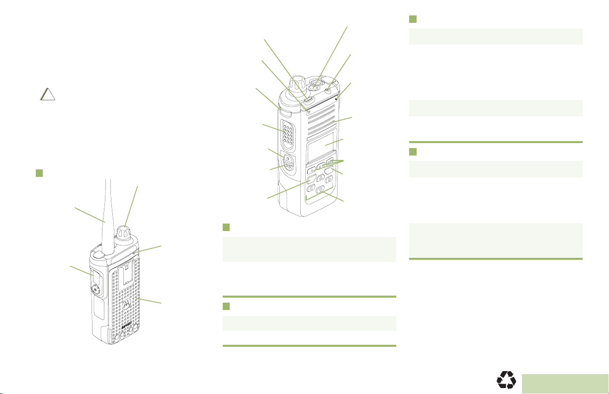
Radio Controls
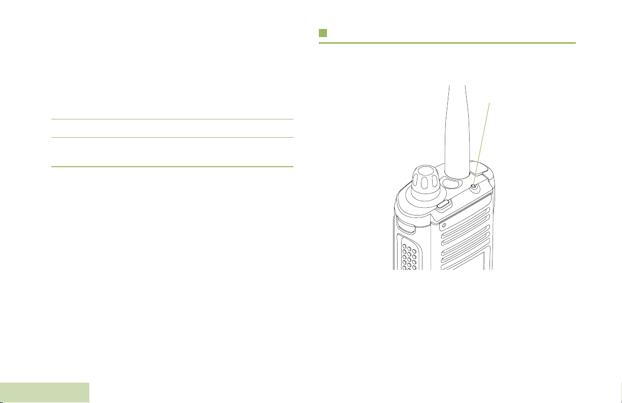
Antenna
Accessory
Connector
ATTENTION!
Multi-Function Knob
(MFK):
Primary Feature:
_________________
Secondary Feature:
_________________
Microphone
Battery
Top (Orange)
Button
Top Lightbar
Microphone
Top Side
(Select)
Button
__________
PTT Button
Side Button 1
__________
Side Button 2
__________
Home Button
__________
LED
®
Bluetooth
Pairing
Indicator
Main
Speaker
Main Display
Menu Select
Buttons
Data Feature
Button
4-Way Navigation
Button
Radio On/Off
• On – Press and hold the MFK until the display
lights up.
• Off – Press and hold the MFK until you see
Power off?, then press Menu Select button
below Yes.
Zones and Channels
Receiving and Transmitting
1 Select zone/channel.
2 Listen for a transmission.
OR
Press and hold Vol u m e Set button.
OR
Press Monitor button and listen for activity.
3 Adjust volume, if necessary.
4 Press the PTT button to transmit; release to
receive.
Sending an Emergency Alarm
1 Press and hold the Emergency button*.
2 The display shows Emergency and the
current zone/channel. Radio sounds a short,
medium-pitched tone, and the LED blinks red
momentarily.
3 When acknowledgment is received, you hear
four beeps; alarm ends; and radio exits
emergency.
* Default emergency button press timer is set
to 1 second. This timer is programmable, see
page 57 in the user guide for details.
To exit emergency at any time, press and hold
the Emergency button.
• Zone – Zone scroll to desired zone.
• Channel – Channel scroll to desired channel.
MOTOROLA, MOTO, MOTOROLA SOLUTIONS and the Stylized M logo are trademarks or registered trademarks of Motorola Trademark Holdings, LLC
and are used under license. All other trademarks are the property of their respective owners. © 2011 by Motorola Solutions, Inc. All Rights Reserved. 05/12
1303 East Algonquin Road, Schaumburg, Illinois 60196, U.S.A.
*PMLN6073B*
PMLN6073B
English
Page 4
Sending an Emergency Call
1 Press the Emergency button.
2 Press and hold the PTT button. Speak clearly
into the microphone.
3 Release the PTT button to end call.
4 Press and hold Emergency button to exit
emergency.
To exit emergency at any time, press and hold
the Emergency button.
Sending a Silent Emergency Call
1 Press the Emergency button.
2 The display does not change; the LED does
not light up, and there is no tone.
3 Silent emergency continues until you:
Press and hold the Emergency button to exit
emergency state.
OR
Press and release the PTT button to exit the
Silent Emergency Alarm mode and enter
regular dispatch or Emergency Call mode.
To exit emergency at any time, press and hold
the Emergency button.
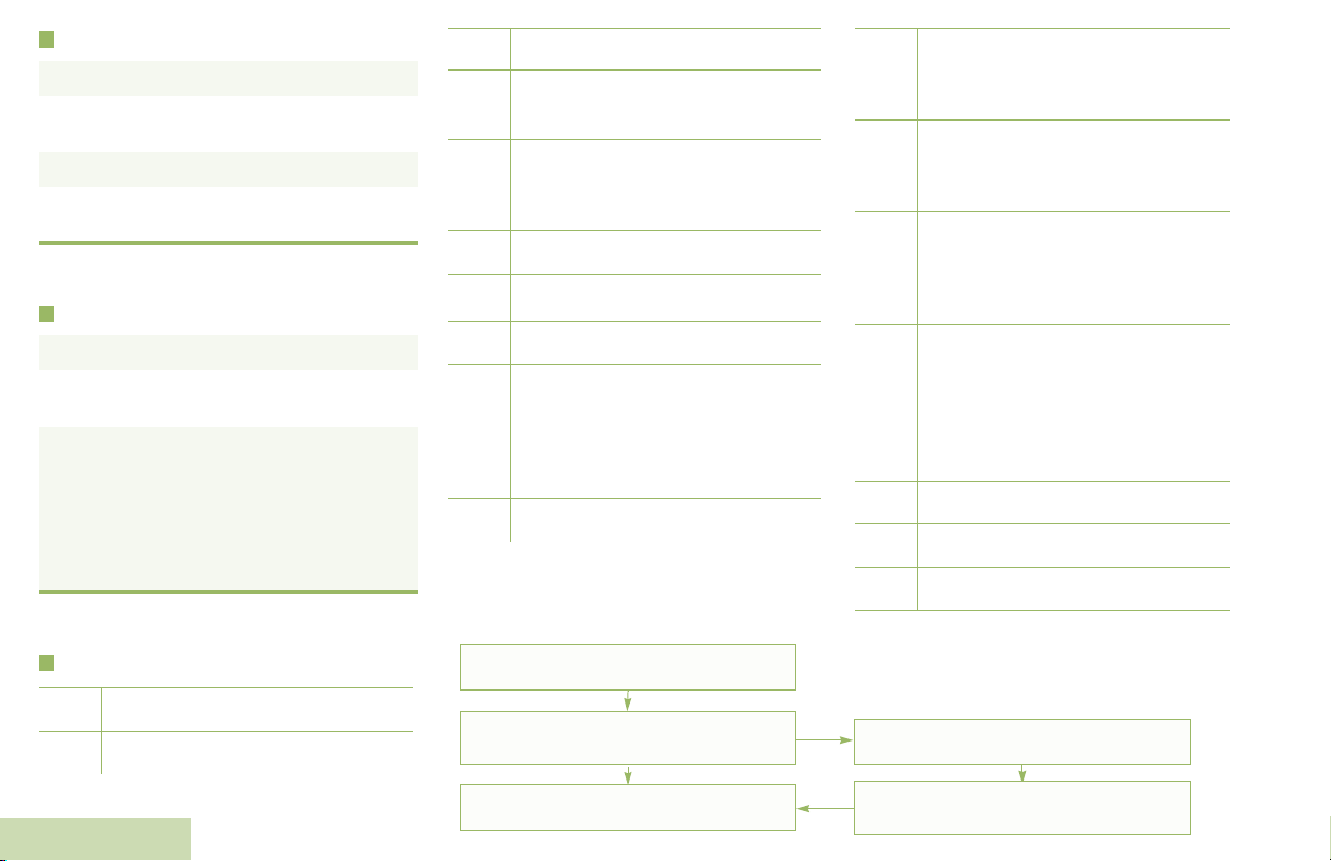
Display Status Icons
8
V
O
M
H
OR .
i
j
k
Blinks when the battery is low.
The more stripes, the stronger the
signal strength for the current site
(trunking only).
Direct radio to radio communication or
connected through a repeater.
On = Direct
Off = Repeater
This channel is being monitored.
L = Radio is set at Low power.
H = Radio is set at High power.
Scanning a scan list.
Blinking dot = Detects activity on the
Priority-One Channel
during scan.
Steady dot = Detects activity on the
Priority-Two Channel
during scan.
The vote scan feature is enabled.
Menu Navigation
< or > to Menu Entry.
On = Secure operation.
Off = Clear operation.
m
Blinking = Receiving an encrypted
voice call.
On = AES Secure operation.
Off = Clear operation.
l
Blinking = Receiving an encrypted
voice call.
On = Location feature enabled, and
G
n
o
b
a
location signal available.
Off = Location feature disabled.
Blinking = Location feature enabled,
but location signal unavailable.
On = User is currently associated with
the radio.
Off = User is currently not associated
with the radio.
Blinking = Device registration or user
registration with the server failed due
to an invalid username or pin.
Data activity is present.
Bluetooth is ready.
Bluetooth is connected to the device.
u
t
English
Receiving a call or data
Transmitting a call or data
{, |, or } directly below
Menu Entry to select.
H to exit.
U or D to scroll through sub-list.
{, |, or } directly below
Menu Entry to select.
Page 5
Declaration of Conformity
This declaration is applicable to your radio only if your radio is labeled with the FCC logo shown below.
DECLARATION OF CONFORMITY
Per FCC CFR 47 Part 2 Section 2.1077(a)
Responsible Party
Name: Motorola Solutions, Inc.
Address: 1303 East Algonquin Road, Schaumburg, Illinois 60196, U.S.A.
Phone Number: 1-800-927-2744
Hereby declares that the product:
Model Name: APX 4000
conforms to the following regulations:
FCC Part 15, subpart B, section 15.107(a), 15.107(d) and section 15.109(a)
Class B Digital Device
As a personal computer peripheral, this device complies with Part 15 of the FCC Rules. Operation is subject to the
following two conditions:
1. This device may not cause harmful interference, and
2. This device must accept any interference received, including interference that may cause undesired operation.
Declaration of Conformity
English
i
Page 6

Note: This equipment has been tested and found to comply with the limits for a Class B digital device, pursuant to part
15 of the FCC Rules. These limits are designed to provide reasonable protection against harmful interference in a
residential installation. This equipment generates, uses and can radiate radio frequency energy and, if not
installed and used in accordance with the instructions, may cause harmful interference to radio communications.
However, there is no guarantee that interference will not occur in a particular installation.
If this equipment does cause harmful interference to radio or television reception, which can be determined by
turning the equipment off and on, the user is encouraged to try to correct the interference by one or more of the
following measures:
• Reorient or relocate the receiving antenna.
• Increase the separation between the equipment and receiver.
• Connect the equipment into an outlet on a circuit different from that to which the receiver is connected.
• Consult the dealer or an experienced radio/TV technician for help.
Declaration of Conformity
ii
English
Page 7

Contents
This User Guide contains all the information you need
to use the APX™ 4000 Series Digital Portable Radios.
Declaration of Conformity . . . . . . . . . . . . . . . . .i
Important Safety Information . . . . . . . . . . . . . .ix
Product Safety and RF Exposure Compliance . . . . .ix
Software Version . . . . . . . . . . . . . . . . . . . . . . . .ix
Notice to Users (FCC and Industry Canada) . . . . . .ix
Disclaimer . . . . . . . . . . . . . . . . . . . . . . . . . . . . . xi
Getting Started . . . . . . . . . . . . . . . . . . . . . . . . . .1
How to Use This Guide . . . . . . . . . . . . . . . . . . . . . . . 1
Notations Used in This Manual . . . . . . . . . . . . . . . . . 1
Additional Performance Enhancement . . . . . . . . . . . 2
Dynamic System Resilience (DSR) . . . . . . . . . . . . . 2
CrossTalk Prevention . . . . . . . . . . . . . . . . . . . . . . . 3
Encrypted Integrated Data (EID) . . . . . . . . . . . . . . . 3
SecureNet . . . . . . . . . . . . . . . . . . . . . . . . . . . . . . . . 3
What Your Dealer/System Administrator
Can Tell You . . . . . . . . . . . . . . . . . . . . . . . . . . . . . . 3
Contents
Informations importantes sur la sécurité . . . . x
Sécurité du produit et respect des lignes directrices
concernant l'exposition à l'énergie RF . . . . . . . . . . . x
Version du logiciel . . . . . . . . . . . . . . . . . . . . . . . x
Avis aux utilisateurs (FCC et Industrie Canada) . . . . x
Computer Software Copyrights . . . . . . . . . . . .xi
Documentation Copyrights . . . . . . . . . . . . . . . .xi
Preparing Your Radio for Use . . . . . . . . . . . . . .4
Charging the Battery . . . . . . . . . . . . . . . . . . . . . . . . . 4
Battery Charger . . . . . . . . . . . . . . . . . . . . . . . . . . . . 4
Attaching the Battery . . . . . . . . . . . . . . . . . . . . . . . . . 5
Attaching the Antenna . . . . . . . . . . . . . . . . . . . . . . . . 6
Attaching the Accessory Connector Cover . . . . . . . . 6
Attaching the Belt Clip . . . . . . . . . . . . . . . . . . . . . . . . 7
Turning On the Radio . . . . . . . . . . . . . . . . . . . . . . . . 7
Adjusting the Volume . . . . . . . . . . . . . . . . . . . . . . . . 8
iii
English
Page 8

Identifying Radio Controls . . . . . . . . . . . . . . . . .9
Radio Parts and Controls . . . . . . . . . . . . . . . . . . . . 10
Programmable Features . . . . . . . . . . . . . . . . . . . . . 11
Assignable Radio Functions . . . . . . . . . . . . . . . . . . 11
Assignable Settings or Utility Functions . . . . . . . . . 13
Accessing the Preprogrammed Functions . . . . . . . 13
Using the Menu Select Buttons . . . . . . . . . . . . . . . 14
Using the Navigation Buttons . . . . . . . . . . . . . . . . . 14
Home Button . . . . . . . . . . . . . . . . . . . . . . . . . . . . . 14
Data Feature Button . . . . . . . . . . . . . . . . . . . . . . . 15
4-Way Navigation Button . . . . . . . . . . . . . . . . . . . . 15
Multi-Function Knob (MFK) . . . . . . . . . . . . . . . . . . 15
Push-To-Talk (PTT) Button . . . . . . . . . . . . . . . . . . 16
Identifying Status Indicators . . . . . . . . . . . . . .16
Status Icons . . . . . . . . . . . . . . . . . . . . . . . . . . . . . . 16
Text Messaging Service (TMS) Icons . . . . . . . . . . 19
Status Icons . . . . . . . . . . . . . . . . . . . . . . . . . . . . . . 19
TMS Menu Options . . . . . . . . . . . . . . . . . . . . . . . . . 21
Call Type Icons . . . . . . . . . . . . . . . . . . . . . . . . . . . . 21
Top Lightbar and LED Indicators . . . . . . . . . . . . . . 22
Contents
LED Indications . . . . . . . . . . . . . . . . . . . . . . . . . . . 23
Top Lightbar Indications . . . . . . . . . . . . . . . . . . . . . 23
Intelligent Lighting Indicators . . . . . . . . . . . . . . . . . 24
iv
Alert Tones . . . . . . . . . . . . . . . . . . . . . . . . . . . . . . . 25
Phone Call Display and Alert Prompts . . . . . . . . . . 29
General Radio Operation . . . . . . . . . . . . . . . . 30
Selecting a Zone . . . . . . . . . . . . . . . . . . . . . . . . . . 30
Selecting a Radio Channel . . . . . . . . . . . . . . . . . . . 31
Using Mode Select Feature . . . . . . . . . . . . . . . . . . 33
Saving a Zone and Channel to a Softkey . . . . . . . .33
Saving a Zone and Channel to a Button . . . . . . . . .34
Receiving and Responding to a Radio Call . . . . . . 34
Receiving and Responding to a Talkgroup Call . . .35
Receiving and Responding to a Private Call
(Trunking Only) . . . . . . . . . . . . . . . . . . . . . . . . . . . .35
Receiving and Responding to a Telephone Call
(Trunking Only) . . . . . . . . . . . . . . . . . . . . . . . . . . . .36
Making a Radio Call . . . . . . . . . . . . . . . . . . . . . . . . 37
Making a Talkgroup Call . . . . . . . . . . . . . . . . . . . . .37
Making a Private Call (Trunking Only) . . . . . . . . . . .37
Making an Enhanced Private Call (Trunking Only) .38
Making a Telephone Call (Trunking Only) . . . . . . . .39
Repeater or Direct Operation . . . . . . . . . . . . . . . . . 40
Monitoring Features . . . . . . . . . . . . . . . . . . . . . . . . 40
Monitoring a Channel . . . . . . . . . . . . . . . . . . . . . . .41
Conventional Mode Operation . . . . . . . . . . . . . . . .41
English
Page 9

Advanced Features . . . . . . . . . . . . . . . . . . . . . 42
Advanced Call Features . . . . . . . . . . . . . . . . . . . . . 42
Receiving and Making a Selective Call (ASTRO
Conventional Only) . . . . . . . . . . . . . . . . . . . . . . . . .42
Receiving a Selective Call . . . . . . . . . . . . . . . . . . .42
Making a Selective Call . . . . . . . . . . . . . . . . . . . . .43
Using the Talkgroup Call Feature (Conventional
Operation Only) . . . . . . . . . . . . . . . . . . . . . . . . . . . .43
Selecting a Talkgroup . . . . . . . . . . . . . . . . . . . . . .43
Sending a Status Call . . . . . . . . . . . . . . . . . . . . . . .44
Using the Dynamic Regrouping Feature
(Trunking Only) . . . . . . . . . . . . . . . . . . . . . . . . . . . .45
Requesting a Reprogram (Trunking Only) . . . . . . . 46
Classifying Regrouped Radios . . . . . . . . . . . . . . . . 46
Using Dynamic Zone Programming (DZP) . . . . . . .46
Entering the Dynamic Zone to Select a Dynamic
Channel . . . . . . . . . . . . . . . . . . . . . . . . . . . . . . . . .47
Saving a Channel in the Dynamic Zone from List
Selection . . . . . . . . . . . . . . . . . . . . . . . . . . . . . . . .47
Deleting a Channel in the Dynamic Zone . . . . . . . . 48
Contacts . . . . . . . . . . . . . . . . . . . . . . . . . . . . . . . . . 48
Making a Private Call from Contacts . . . . . . . . . . . .49
Adding a Contact to a Call List . . . . . . . . . . . . . . . .50
Removing a Contact from a Call List . . . . . . . . . . . .50
Scan Lists . . . . . . . . . . . . . . . . . . . . . . . . . . . . . . . . 51
Viewing a Scan List . . . . . . . . . . . . . . . . . . . . . . . . .51
Editing the Scan List . . . . . . . . . . . . . . . . . . . . . . . .51
Changing the Scan List Status . . . . . . . . . . . . . . . 52
Viewing and Changing the Priority Status . . . . . . 52
Scan . . . . . . . . . . . . . . . . . . . . . . . . . . . . . . . . . . . . 53
Turning Scan On or Off . . . . . . . . . . . . . . . . . . . . . 53
Making a Dynamic Priority Change (Conventional
Scan Only) . . . . . . . . . . . . . . . . . . . . . . . . . . . . . . . 53
Deleting a Nuisance Channel . . . . . . . . . . . . . . . . 53
Restoring a Nuisance Channel . . . . . . . . . . . . . . . 54
Call Alert Paging . . . . . . . . . . . . . . . . . . . . . . . . . . . 54
Receiving a Call Alert Page . . . . . . . . . . . . . . . . . . 54
Sending a Call Alert Page . . . . . . . . . . . . . . . . . . . 55
Emergency Operation . . . . . . . . . . . . . . . . . . . . . . . 56
Sending an Emergency Alarm . . . . . . . . . . . . . . . . 57
Sending an Emergency Call (Trunking Only) . . . . 57
Sending an Emergency Alarm with
Emergency Call . . . . . . . . . . . . . . . . . . . . . . . . . . . 58
Sending a Silent Emergency Alarm . . . . . . . . . . . . 58
Using the Emergency Keep-Alive Feature . . . . . . . 59
Man Down . . . . . . . . . . . . . . . . . . . . . . . . . . . . . . . . 59
Pre-Alert Timer . . . . . . . . . . . . . . . . . . . . . . . . . . . 60
Post-Alert Timer . . . . . . . . . . . . . . . . . . . . . . . . . . . 61
Alerting User When Man Down Feature is
Triggered . . . . . . . . . . . . . . . . . . . . . . . . . . . . . . . . 61
Triggering Emergency . . . . . . . . . . . . . . . . . . . . . . 61
Exiting Man Down Feature . . . . . . . . . . . . . . . . . . 62
Re-Initiating Man Down . . . . . . . . . . . . . . . . . . . . . 62
Testing the Man Down Feature . . . . . . . . . . . . . . . 62
Contents
v
English
Page 10

vi
Automatic Registration Service (ARS) . . . . . . . . . . 64
Selecting or Changing the ARS Mode . . . . . . . . . . 64
Accessing the User Login Feature . . . . . . . . . . . . . 65
Logging In as a User . . . . . . . . . . . . . . . . . . . . . . . 65
Logging Out . . . . . . . . . . . . . . . . . . . . . . . . . . . . . . 66
Text Messaging Service (TMS) . . . . . . . . . . . . . . . 66
Accessing the TMS Features . . . . . . . . . . . . . . . . . 67
Sending a Quick Text Message . . . . . . . . . . . . . . . 67
Using the Priority Status and Request Reply
Features . . . . . . . . . . . . . . . . . . . . . . . . . . . . . . . . . 68
Appending a Priority Status to a Text Message . . . 68
Removing a Priority Status from a Text Message . 69
Appending a Request Reply to a Text Message . . 69
Removing a Request Reply from a Text Message 69
Appending a Priority Status and a Reply Request
to a Text Message . . . . . . . . . . . . . . . . . . . . . . . . . 69
Removing a Priority Status and a Reply Request
from a Text Message . . . . . . . . . . . . . . . . . . . . . . . 70
Managing Text Messages . . . . . . . . . . . . . . . . . . . 70
Receiving a Text Message . . . . . . . . . . . . . . . . . . 70
Viewing a Text Message from the Inbox . . . . . . . . 71
Replying to a Received Text Message . . . . . . . . . 71
Managing Sent Text Messages . . . . . . . . . . . . . . . 72
Contents
Viewing a Sent Text Message . . . . . . . . . . . . . . . . 72
Sending a Sent Text Message . . . . . . . . . . . . . . . 73
Deleting a Text Message . . . . . . . . . . . . . . . . . . . . 73
Deleting All Text Messages . . . . . . . . . . . . . . . . . . 74
Secure Operations . . . . . . . . . . . . . . . . . . . . . . . . . 74
Selecting Secure Transmissions . . . . . . . . . . . . . . .74
Selecting Clear Transmissions . . . . . . . . . . . . . . . .75
Managing Encryption . . . . . . . . . . . . . . . . . . . . . . .75
Loading an Encryption Key . . . . . . . . . . . . . . . . . .75
Using the Multikey Feature . . . . . . . . . . . . . . . . . . .75
Selecting an Encryption Key . . . . . . . . . . . . . . . . .76
Selecting a Keyset . . . . . . . . . . . . . . . . . . . . . . . . .76
Erasing the Selected Encryption Keys . . . . . . . . . .77
Requesting an Over-the-Air Rekey
(ASTRO Only) . . . . . . . . . . . . . . . . . . . . . . . . . . . .78
MDC Over-the-Air Rekeying (OTAR) Page . . . . . .78
Hear Clear . . . . . . . . . . . . . . . . . . . . . . . . . . . . . . .79
The Global Positioning System (GPS) . . . . . . . . . . 79
Understanding the GPS Feature . . . . . . . . . . . . . . .79
Enhancing GPS Performance . . . . . . . . . . . . . . . . .80
The Outdoor Location Feature (Using GPS) . . . . . .80
Accessing the Outdoor Location Feature . . . . . . . .81
Saving a Waypoint . . . . . . . . . . . . . . . . . . . . . . . . .82
Viewing a Saved Waypoint . . . . . . . . . . . . . . . . . . .83
Deleting a Single Saved Waypoint . . . . . . . . . . . . .83
Deleting All Saved Waypoints . . . . . . . . . . . . . . . .84
Measuring the Distance and Bearing from a
Saved Waypoint . . . . . . . . . . . . . . . . . . . . . . . . . . .84
Using the Location Feature While in Emergency
Mode . . . . . . . . . . . . . . . . . . . . . . . . . . . . . . . . . . .85
Trunking System Controls . . . . . . . . . . . . . . . . . . . 85
Using the Failsoft System . . . . . . . . . . . . . . . . . . . .85
Going Out of Range . . . . . . . . . . . . . . . . . . . . . . . .86
English
Page 11

Using the Site Trunking Feature . . . . . . . . . . . . . . .86
Locking and Unlocking a Site . . . . . . . . . . . . . . . . .86
Viewing and Changing a Site . . . . . . . . . . . . . . . . . 87
Viewing the Current Site . . . . . . . . . . . . . . . . . . . .87
Changing the Current Site . . . . . . . . . . . . . . . . . . .87
Mission Critical Wireless
- Bluetooth® - . . . . . . . . . . . . . . . . . . . . . . . . . . . . 87
Turning the Bluetooth On . . . . . . . . . . . . . . . . . . . .88
Turning the Bluetooth Off . . . . . . . . . . . . . . . . . . . .88
Re-Pair Timer . . . . . . . . . . . . . . . . . . . . . . . . . . . . .89
Bluetooth Drop Timer . . . . . . . . . . . . . . . . . . . . . . .90
Pairing Bluetooth Device with the Radio . . . . . . . . .90
Indicating Bluetooth Connection is Lost . . . . . . . . .91
Turning On the Bluetooth Audio (Routing the Audio
from the Radio to the Headset) . . . . . . . . . . . . . . . .92
Turning Off the Bluetooth Audio (Routing the Audio
from the Headset to the Radio) . . . . . . . . . . . . . . . .92
Adjusting the Volume of the Radio from Bluetooth
Audio Device . . . . . . . . . . . . . . . . . . . . . . . . . . . . . .93
Viewing and Clearing the Bluetooth Device
Information . . . . . . . . . . . . . . . . . . . . . . . . . . . . . . .93
Clearing All Bluetooth Devices Information . . . . . . .94
Viewing the Bluetooth Friendly Name . . . . . . . . . . .94
Programming Over Project 25 (POP 25) (ASTRO 25
and ASTRO Conventional) . . . . . . . . . . . . . . . . . . 95
Responding to the notification of Upgrade . . . . . . .95
Utilities . . . . . . . . . . . . . . . . . . . . . . . . . . . . . . . . . . 96
Viewing the Recent Calls . . . . . . . . . . . . . . . . . . . . 96
Selecting the Power Level . . . . . . . . . . . . . . . . . . . 97
Selecting a Radio Profile . . . . . . . . . . . . . . . . . . . . 97
Enabling and Disabling the Radio Alias . . . . . . . . . 98
Selecting the Audio Speaker . . . . . . . . . . . . . . . . . 99
Controlling the Display Backlight . . . . . . . . . . . . . 100
Locking and Unlocking the Keypad and Controls 100
Turning Keypad Tones On or Off . . . . . . . . . . . . . 100
Turning Voice Mute On or Off . . . . . . . . . . . . . . . 101
Using the Time-Out Timer . . . . . . . . . . . . . . . . . . 101
Setting the Time and Date . . . . . . . . . . . . . . . . . . 102
Editing the Time and Date . . . . . . . . . . . . . . . . . 102
Using the Conventional Squelch Operation
Features . . . . . . . . . . . . . . . . . . . . . . . . . . . . . . . . 103
Analog Options . . . . . . . . . . . . . . . . . . . . . . . . . . 103
Digital Options . . . . . . . . . . . . . . . . . . . . . . . . . . 103
Using the PL Defeat Feature . . . . . . . . . . . . . . . . 104
Using the Digital PTT ID Feature . . . . . . . . . . . . . 104
Using the Smart PTT Feature
(Conventional Only) . . . . . . . . . . . . . . . . . . . . . . . 104
IMPRES™ Battery Annunciator . . . . . . . . . . . . . . 105
Accessing the Battery Info screen . . . . . . . . . . . 105
Accessing the General Radio Information . . . . . . 106
Accessing the Radio Information . . . . . . . . . . . . 106
Viewing the IP Information . . . . . . . . . . . . . . . . . 107
Viewing the Control Assignments . . . . . . . . . . . . 108
Voice Announcement . . . . . . . . . . . . . . . . . . . . . . 108
Contents
vii
English
Page 12

Helpful Tips . . . . . . . . . . . . . . . . . . . . . . . . . . .110
Acoustic Safety . . . . . . . . . . . . . . . . . . . . . . . . . . 110
Caring for Your Radio . . . . . . . . . . . . . . . . . . . . . . 111
Cleaning Your Radio . . . . . . . . . . . . . . . . . . . . . . 112
Handling Your Radio . . . . . . . . . . . . . . . . . . . . . . 112
Servicing Your Radio . . . . . . . . . . . . . . . . . . . . . . 113
Taking Care of the Battery . . . . . . . . . . . . . . . . . . 113
Checking the Battery Charge Status . . . . . . . . . . 113
LED and Sounds . . . . . . . . . . . . . . . . . . . . . . . . . 113
Fuel Gauge Icon . . . . . . . . . . . . . . . . . . . . . . . . . 114
Battery Recycling and Disposal . . . . . . . . . . . . . . 114
Accessories . . . . . . . . . . . . . . . . . . . . . . . . . . .115
Highlights for the Accessories . . . . . . . . . . . . . . . 115
Appendix: Maritime Radio Use in the VHF
Frequency Range . . . . . . . . . . . . . . . . . . . . . .116
Special Channel Assignments . . . . . . . . . . . . . . . 116
Emergency Channel . . . . . . . . . . . . . . . . . . . . . . . 116
Non-Commercial Call Channel . . . . . . . . . . . . . . . 116
Operating Frequency Requirements . . . . . . . . . . 117
Contents
Glossary . . . . . . . . . . . . . . . . . . . . . . . . . . . . .119
Commercial Warranty . . . . . . . . . . . . . . . . . . 124
viii
English
Page 13

Important Safety Information
C
n
Product Safety and RF Exposure Compliance
Before using this product, read the operating
instructions for safe usage contained in the
!
a u t i o
Product Safety and RF Exposure booklet
enclosed with your radio.
ATTENTION!
This radio is restricted to occupational use only to
satisfy FCC RF energy exposure requirements.
Before using this product, read the RF energy awareness
information and operating instructions in the Product
Safety and RF Exposure booklet enclosed with your radio
(Motorola Publication part number 6881095C98) to
ensure compliance with RF energy exposure limits.
For a list of Motorola-approved antennas, batteries, and
other accessories, visit the following website:
http://www.motorolasolutions.com/APX
Under Industry Canada regulations, this radio transmitter may
only operate using an antenna of a type and maximum (or
lesser) gain approved for the transmitter by Industry Canada.
To reduce potential radio interference to other users, the
antenna type and its gain should be so chosen that the
equivalent isotropically radiated power (e.i.r.p.) is not more than
that necessary for successful communication.
Important Safety Information
ix
English
Page 14

Software Version
All the features described in the following sections are
supported by the radio's software version R08.00.00 or
later.
See Accessing the Radio Information on page 106 to
determine your radio's software version.
Check with your dealer or system administrator
for more details of all the features supported.
Notice to Users (FCC and Industry Canada)
This device complies with Part 15 of the FCC rules and
RSS 210 of the Industry Canada rules per the conditions
listed below:
1 This device may not cause harmful interference.
2 This device must accept any interference received,
including interference that may cause undesired
operation.
3 Changes or modifications made to this device, not
expressly approved by Motorola, could void the user's
authority to operate this equipment.
Software Version
Informations importantes sur la sécurité
Sécurité du produit et respect des lignes directrices concernant l'exposition à l'énergie RF
Avant d'utiliser ce produit, lisez les directives
!
Mise en garde
d'utilisation sécuritaire présentées dans le livret
Sécurité du produit et exposition à l'énergie RF
accompagnant votre radio.
x
Français Canadien
Page 15

ATTENTION!
Cette radio est réservée à un usage professionnel
seulement pour satisfaire les normes d'exposition
à l'énergie RF de la FCC. Avant d'utiliser ce produit,
lisez l'information sur la sensibilisation à l'énergie RF
et les directives d'utilisation présentées dans le livret
Sécurité du produit et exposition à l'énergie RF
accompagnant votre radio (publication de Motorola,
numéro d'article 6881095C98) pour assurer le respect
des limites d'exposition à l'énergie RF.
Pour obtenir une liste d'antennes et d'autres accessoires
approuvés par Motorola, consultez le site Web:
http://www.motorolasolutions.com/APX
Selon la règlementation d'Industrie Canada, cet émetteur radio
ne peut être utilisé qu'avec une antenne dont le type et le gain
maximal (ou minimal) sont approuvés par Industrie Canada
pour cet émetteur. Afin de limiter les interférences radio pour les
autres utilisateurs, le type et le gain de l'antenne doivent être
choisis de façon à ce que la puissance isotrope rayonnée
équivalente (P.I.R.E.) ne soit pas plus forte qu'il ne le faut pour
établir la communication.
Version du logiciel
Version du logiciel
Toutes les fonctionnalités décrites dans les sections
suivantes sont prises en charge par la version du logiciel
R08.00.00 ou ultérieure de la radio.
Vérifiez auprès de votre détaillant ou de l'administrateur
de système pour obtenir des renseignements toutes les
fonctionnalités prises en charge.
Avis aux utilisateurs (FCC et Industrie Canada)
Cet appareil est conforme à la Partie 15 des règlements
de la FCC et RSS 210 du règlement d'Industrie Canada
selon les conditions énumérées ci-dessous:
1 Ce dispositif ne doit pas causer d'interférences
nuisibles.
2 Cet appareil doit accepter toute interférence reçue, y
compris les interférences qui peuvent perturber le
fonctionnement.
3 Les changements ou les modifications apportées à ce
dispositif, non expressément approuvées par Motorola,
peuvent annuler le droit de l'utilisateur à utiliser cet
équipement.
English
xi
Page 16

Computer Software Copyrights
Documentation Copyrights
The Motorola products described in this manual may
include copyrighted Motorola computer programs stored
in semiconductor memories or other media. Laws in the
United States and other countries preserve for Motorola
certain exclusive rights for copyrighted computer
programs, including, but not limited to, the exclusive right
to copy or reproduce in any form the copyrighted
computer program. Accordingly, any copyrighted
Motorola computer programs contained in the Motorola
products described in this manual may not be copied,
reproduced, modified, reverse-engineered, or distributed
in any manner without the express written permission of
Motorola. Furthermore, the purchase of Motorola
products shall not be deemed to grant either directly or by
implication, estoppel, or otherwise, any license under the
copyrights, patents or patent applications of Motorola,
except for the normal non-exclusive license to use that
arises by operation of law in the sale of a product.
Computer Software Copyrights
No duplication or distribution of this document or any
portion thereof shall take place without the express
written permission of Motorola. No part of this manual
may be reproduced, distributed, or transmitted in any
form or by any means, electronic or mechanical, for any
purpose without the express written permission of
Motorola.
Disclaimer
The information in this document is carefully examined,
and is believed to be entirely reliable. However, no
responsibility is assumed for inaccuracies. Furthermore,
Motorola reserves the right to make changes to any
products herein to improve readability, function, or
design. Motorola does not assume any liability arising out
of the applications or use of any product or circuit
described herein; nor does it cover any license under its
patent rights, nor the rights of others.
xii
English
Page 17
Getting Started
W
G
C
n
Take a moment to review the following:
How to Use This Guide . . . . . . . . . . . . . . . . . . . . . . . . . page 1
Notations Used in This Manual . . . . . . . . . . . . . . . . . . . page 1
Additional Performance Enhancement . . . . . . . . . . . . . page 2
What Your Dealer/System Administrator
Can Tell You. . . . . . . . . . . . . . . . . . . . . . . . . . . . . . . . page 3
How to Use This Guide
Notations Used in This Manual
Throughout the text in this publication, you will notice the use of
WARNING, Caution, and Note. These notations are used to
emphasize that safety hazards exist, and the care that must be
taken or observed.
An operational procedure, practice, or condition,
!
!
A R N I N
etc., which may result in injury or death if not
carefully observed.
Getting Started
This User Guide covers the basic operation of the APX™ 4000
Portables.
However, your dealer or system administrator may have
customized your radio for your specific needs. Check with your
dealer or system administrator for more information.
!
a u t i o
Note:
An operational procedure, practice, or
condition, etc., which may result in damage
to the equipment if not carefully observed.
An operational procedure, practice, or condition,
etc., which is essential to emphasize.
1
English
Page 18

The following special notations identify certain items:
Additional Performance Enhancement
Getting Started
Example Description
Home button
or H
Phone
>
Buttons and keys are shown in bold print
or as an icon.
Menu entries are shown similar to the
way they appear on your radio’s display.
This means “Press the right side of the
4-way Navigation button”.
The following are some of the latest creations designed to
enhance the security, quality and efficiency of your radio.
Dynamic System Resilience (DSR)
DSR ensures your radio system is seamlessly switched to a
backup master site dynamically in case of system failure.
DSR also provides additional indication e.g. failure detection,
fault recovery, and redundancy within the system to address to
the user in need. Mechanisms related to the Integrated Voice
and Data (IV & D) or data centric are all supported by DSR.
2
English
Page 19

CrossTalk Prevention
This feature prevents crosstalk scenario from happening,
especially when a wideband antenna is used. This feature
allows the adjustment of the Trident Transmitting SSI clock rate
in your radio to be varied from the Receiving Frequency. This
subsequently reduced the possibilities of radio frequency
interfering spurs and prevents the issues of crosstalk.
Encrypted Integrated Data (EID)
EID provides security encryption and authentication of IV & D
data bearer service communication between your radio and the
Customer Enterprise Network.
SecureNet
SecureNet allows user to perform secured communications on
an Analog or Motorola Data Communication (MDC) channel.
The MDC OTAR feature will allow users to perform OTAR
activities on an MDC channel.
What Your Dealer/System Administrator Can Tell You
Check with your dealer or system administrator for the correct
radio settings, if the radio is to be operated in extreme
temperatures (less than -30 °C or more than +60 °C), to ensure
proper top and front display operation.
You can also consult your dealer or system administrator about
the following:
• Is your radio preprogrammed with any preset conventional
channels?
• Which buttons have been preprogrammed to access other
features?
• What optional accessories may suit your needs?
Getting Started
English
3
Page 20
Preparing Your Radio for Use
W
G
Charging the Battery
Assemble your radio by following these steps:
Charging the Battery . . . . . . . . . . . . . . . . . . . . . . . . . . . page 4
Battery Charger . . . . . . . . . . . . . . . . . . . . . . . . . . . . . page 4
Attaching the Battery. . . . . . . . . . . . . . . . . . . . . . . . . . . page 5
Attaching the Antenna. . . . . . . . . . . . . . . . . . . . . . . . . . page 6
Attaching the Accessory Connector Cover . . . . . . . . . . page 6
Attaching the Belt Clip. . . . . . . . . . . . . . . . . . . . . . . . . . page 7
Turning On the Radio . . . . . . . . . . . . . . . . . . . . . . . . . . page 7
Adjusting the Volume . . . . . . . . . . . . . . . . . . . . . . . . . . page 8
Preparing Your Radio for Use
To avoid a possible explosion:
!
!
A R N I N
The Motorola-approved battery shipped with your radio is
uncharged. Prior to using a new battery, charge it for a minimum
of 16 hours to ensure optimum capacity and performance.
For a list of Motorola-authorized batteries available for use
with your radio, see Accessories on page 115.
Note: When charging a battery attached to a radio, turn your
Battery Charger
To charge the battery, place the battery, with or without the
radio, in a Motorola-approved charger. The charger’s LED
indicates the charging progress; see your charger’s user guide.
For a list of chargers, see Accessories on page 115.
• DO NOT replace the battery in any area
labeled “hazardous atmosphere”.
• DO NOT discard batteries in a fire.
radio off to ensure a full charge.
4
English
Page 21
Attaching the Battery
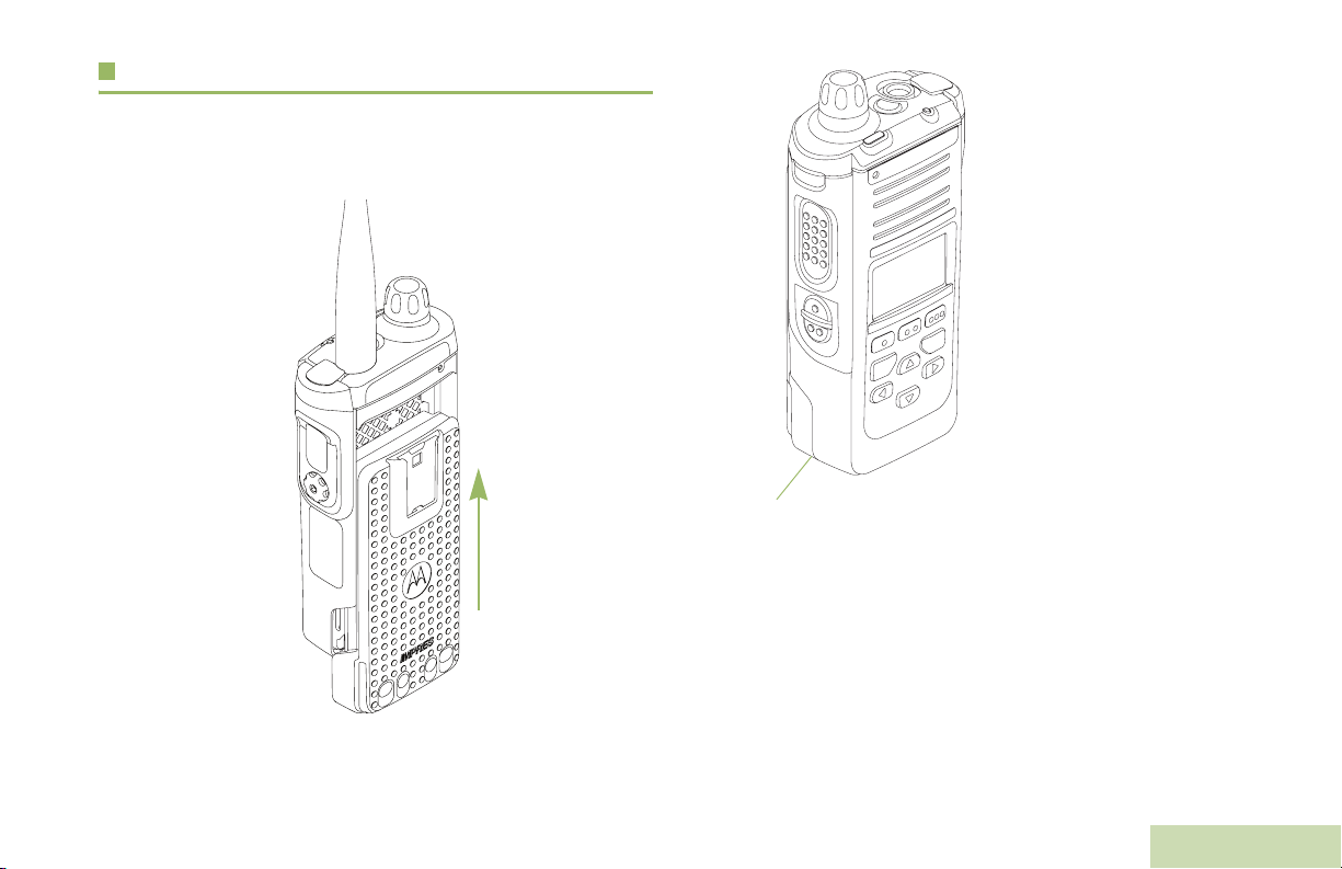
With the radio turned off, slide the battery into the radio’s frame
until the bottom latch clicks into place.
To remove the battery,
turn the radio off. Lift up
the latch then slide the
battery down to remove
the battery from the radio.
Note: If your radio is
preprogrammed
with volatile-key
retention, the
encryption keys
are retained for
approximately 30
seconds after
battery removal.
Check with your
dealer or system
Battery Latch is at the bottom of the battery.
You can view the status of the IMPRES™ battery if the radio is
using an IMPRES™ battery. See IMPRES™ Battery
Annunciator on page 105 for more information.
administrator for
more information.
Preparing Your Radio for Use
English
5
Page 22
Attaching the Antenna
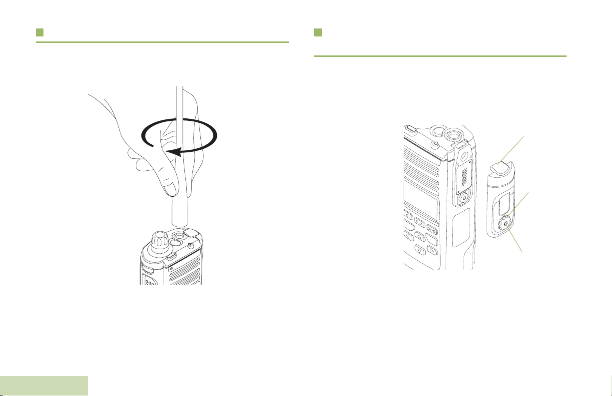
With the radio turned off, set the antenna in its receptacle and
turn clockwise to attach it to the radio.
Attaching the Accessory Connector Cover
The accessory connector is located on the antenna side of the
radio. It is used to connect accessories to the radio.
Note: To prevent damage to the connector, shield it with the
connector cover when not in use.
To remove the antenna, turn the antenna counterclockwise.
Make sure you turn off the radio first.
Preparing Your Radio for Use
6
English
Insert the hooked
end of the cover
into the slot above
the connector.
Press downward on
the cover’s top to
seat it in the slot.
Once in place,
tighten by rotating
the thumbscrew
clockwise by hand.
To remove the
accessory connector cover, rotate the thumbscrew
counterclockwise until it disengages from the radio.
If the thumbscrew is too tight, use an Allen wrench to loosen
it first.
Rotate and lift the connector cover to disengage it from
the radio.
Hooked End
Thumbscrew
Hex Socket Head
Page 23
Attaching the Belt Clip
Turning On the Radio
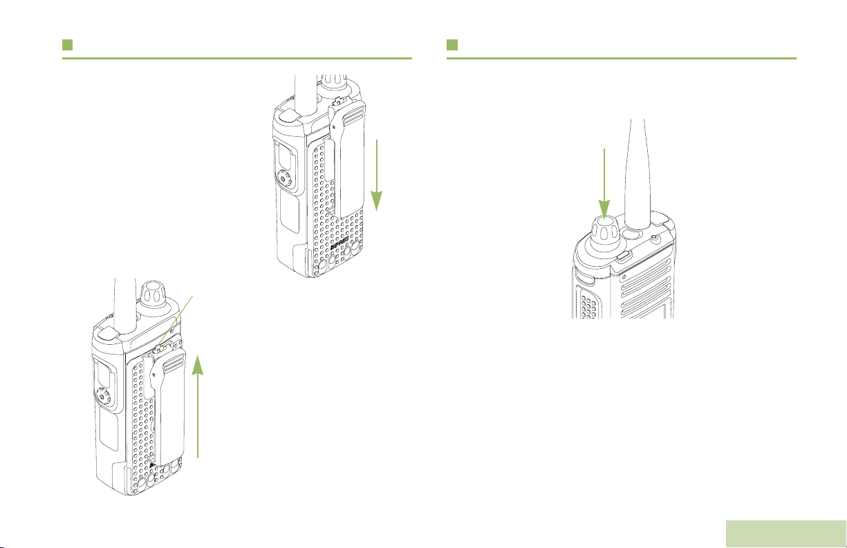
Align the grooves of the belt clip
with those of the radio and
press upward until you hear a
click.
Ta b
To remove the clip, use a flatbladed object to press the belt
clip tab away from the radio.
Then, slide the clip downward
and away from your radio.
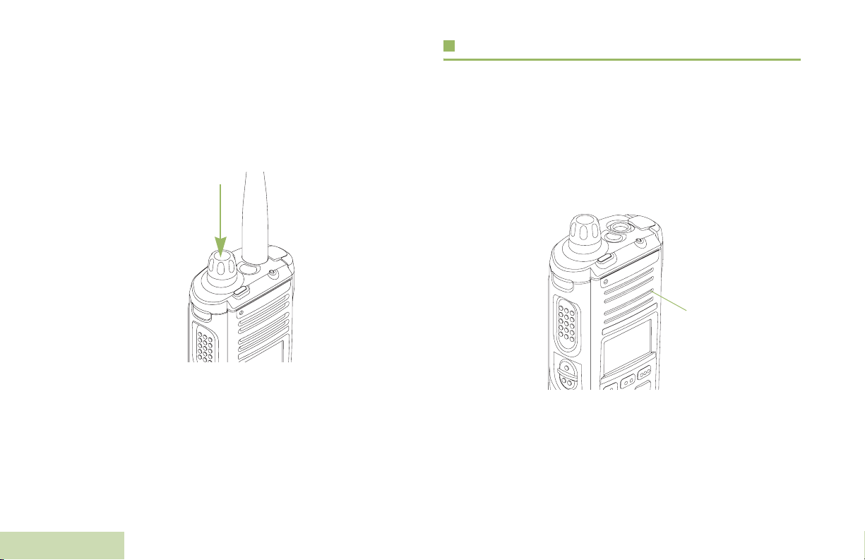
Press and hold the Multi-Function Knob (MFK) until the radio
display lights up, then release the MFK.
If the power-up test is successful, you see the Home screen.
Note: If the power-up test is unsuccessful, you see Error
XX/YY (XX/YY is an alphanumeric code).
Turn off your radio, check the battery, and turn the
radio back on. If your radio fails the power-up test
again, record the Error XX/YY code and contact
your dealer.
Preparing Your Radio for Use
English
7
Page 24
Note: If the power-up test is successful, but you see
Hardware board absent or Hw Board Mismatch.
Send your radio to the qualified technician to fix this
error.
If the power-up test is successful, but you see Hw
Board Failed or Man-Down Hw Error, send your radio
to the qualified technician to fix this error.
To turn off your radio, press and hold the MFK until the radio
display shows
below
Yes
Power off?
to power off.
, press the Menu Select button
Preparing Your Radio for Use
Adjusting the Volume
To increase the volume, turn the MFK clockwise. The display
shows volume bars and volume level when you change the
volume.
Note: If Volume Change is secondary feature of MFK, see
Multi-Function Knob (MFK) on page 15 to toggle the
function of the MFK.
Main
Speaker
To decrease the volume, turn this MFK counterclockwise.
Note: Ensure that the main speaker is pointed towards you
for increased loudness and intelligibility, especially in
areas with loud background noises.
8
English
Page 25

Identifying Radio Controls
Take a moment to review the following:
Radio Parts and Controls . . . . . . . . . . . . . . . . . . . . . . page 10
Programmable Features . . . . . . . . . . . . . . . . . . . . . . . page 11
Assignable Radio Functions . . . . . . . . . . . . . . . . . . page 11
Assignable Settings or Utility Functions. . . . . . . . . . page 13
Accessing the Preprogrammed Functions. . . . . . . . . . page 13
Using the Menu Select Buttons . . . . . . . . . . . . . . . . page 14
Using the Navigation Buttons. . . . . . . . . . . . . . . . . . page 14
Push-To-Talk (PTT) Button . . . . . . . . . . . . . . . . . . . . . page 16
Identifying Radio Controls
English
9
Page 26
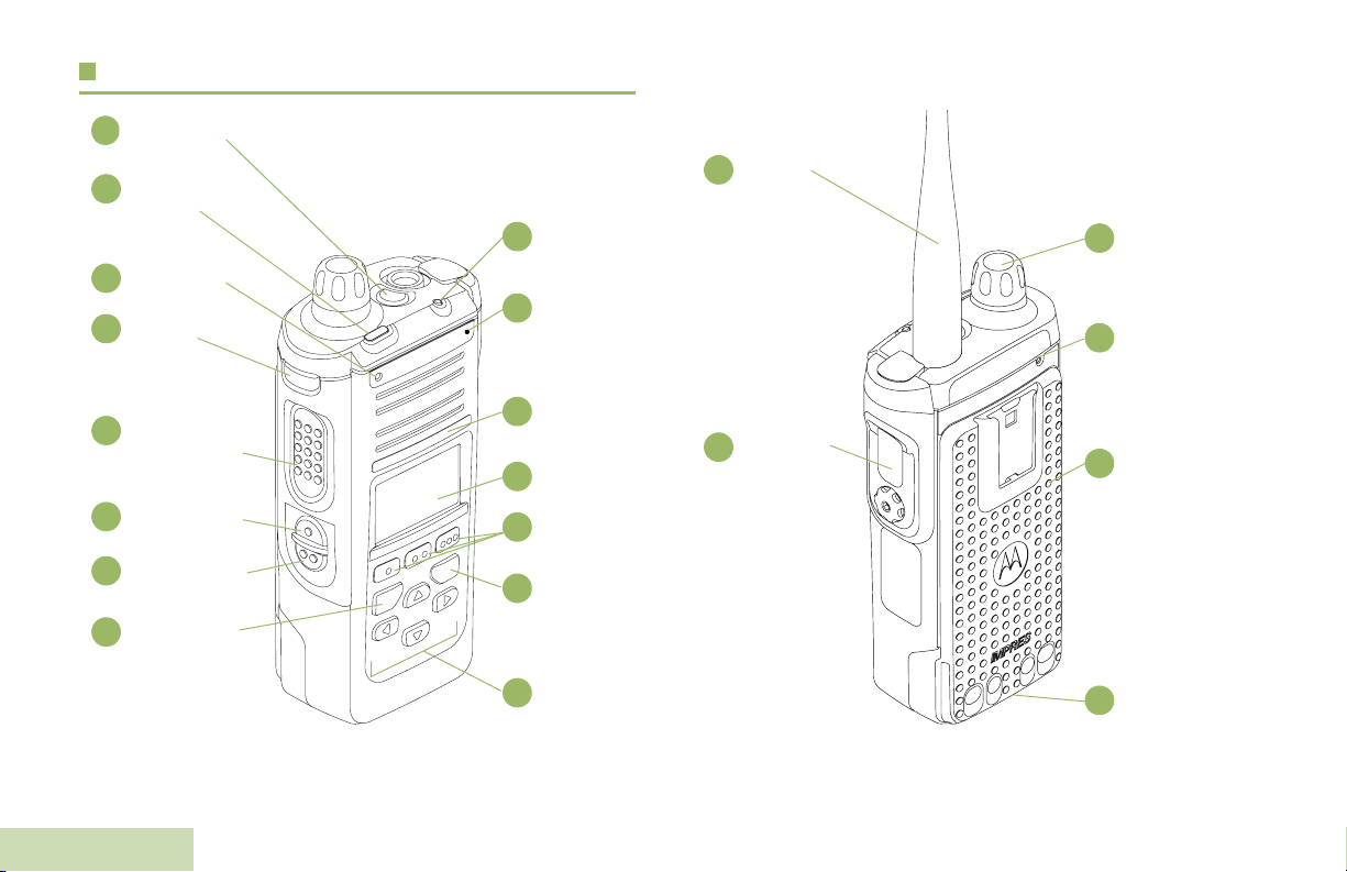
Radio Parts and Controls
Top (Orange)
1
Button*
To p
2
Lightbar
Microphone
3
Top Side
4
(Select)
Button*
Push-to-Talk
5
(PTT) Button
LED
15
14
Bluetooth®
Pairing
Indicator
Speaker
13
Main Display
12
Antenna
16
Accessory
17
Connector
MultiFunction
21
Knob
(MFK)*
Microphone
20
Battery
19
Side Button 1*
6
Side Button 2*
7
Home Button
8
Identifying Radio Controls
10
English
Menu Select
11
Buttons
Data Feature
10
Button
4-Way
9
Navigation
Button
Battery
Latch (at the
18
bottom)
* These radio controls/buttons are programmable.
Page 27

Programmable Features
Any reference in this manual to a control that is
“preprogrammed” means that the control must be programmed
by a dealer or qualified radio technician using the radio's
programming software, in order to assign a feature to that
control.
The programmable buttons can be programmed as shortcuts to
radio functions or preset channels/groups depending on the
duration of a button press:
• Press – Pressing and releasing rapidly.
• Long press – Pressing and holding for the preprogrammed
duration (between 0.25 seconds and 3.75
seconds).
• Hold down – Keeping the button pressed.
Bluetooth Headset and PTT – Keys up the Bluetooth
Headset's microphone.
Bluetooth Data Devices – Keys up the Bluetooth data devices.
Bluetooth Clear All Pairing – Allows you to clear all pairing
information for Bluetooth.This is accessed by a long press of the
Bluetooth On/Off Button.
Call Alert – Allows the radio to function like a pager, or to verify
if a radio is active on the system.
Call Response – Allows you to answer a private call.
Channel – Selects a channel.
Contacts – Selects the Contacts menu.
Dynamic Priority (Conventional Only) – Allows any channel
in a scan list (except for the Priority-One channel) to temporarily
replace the Priority-Two channel.
Identifying Radio Controls
Assignable Radio Functions
Bluetooth On/Off – Allows you to turn on/off the Bluetooth.
Bluetooth Configuration – Allows you to access to the
Bluetooth menu.
Bluetooth Audio Reroute – Allows you to toggle the audio
route between radio speaker or Remote Speaker Microphone
and Bluetooth headset.
Emergency – Depending on the programming, initiates or
cancels an emergency alarm or call.
Information – Displays the information of the radio.
Internet Protocol Address – Displays the Internet Protocol (IP)
address, device name and status of the radio.
Location – Determines the current location (latitude, longitude,
time and date), and also the distance and bearing to another
location. Or, turns the GPS functionality on or off for all location.
11
English
Page 28

Man Down Clear – Clears the alarm of Man Down mode which
was triggered when the radio achieves or passes a tilt angle
threshold or a combination of the angle threshold and a motion
sensitivity level.
Message – Enters the current message list.
Mode Select – Long-press programs a button with the radio's
current zone and channels; then once programmed, the shortpress of that button changes the transmission to the
programmed zone and channel.
Monitor (Conventional Only) – Monitors a selected channel
for all radio traffic until function is disabled.
Multiple Private Line (Conventional Only) – Selects the
Multiple Private Line lists.
Nuisance Delete – Temporarily removes an unwanted channel,
except for priority channels or the designated transmit channel,
from the scan list.
Private Line Defeat (Conventional Only) – Overrides any
coded squelch (DPL or PL) that is preprogrammed to a channel.
Radio Profiles – Allows for easy access to a set of
preprogrammed visual and audio settings of the radio.
Recent Calls – Allows for easy access to the list of calls
recently received or made.
Rekey Request – Notifies the dispatcher you want a new
encryption keys.
Repeater Access Button (RAB) (Conventional Only) –
Allows to manually send a repeater access codeword.
Reprogram Request (Trunking Only) – Notifies the dispatcher
you want a new dynamic regrouping assignment.
Request-To-Talk (Conventional Only) – Notifies the
dispatcher you want to send a voice call.
Scan – Toggles scan on or off.
One Touch 1 – 4 – Launches a specific feature with one single
button-press. You can setup as many as four separately
programmed buttons for four different features.
Phone – Allows you to make and receive calls similar to
standard phone calls.
Private Call (Trunking Only) – Allows a call from an individual
Identifying Radio Controls
radio to another individual radio.
12
English
Secure Transmission Select (Conventional and Trunking) –
Toggles to transmit is secure or clear transmission.
Selective Call (Conventional Only) – Calls an assigned radio.
Site Display/Search (Trunking Only) – Displays the current
site ID and RSSI value; performs site search for AMSS
(Automatic Multiple Site Select) or SmartZone operation.
Site Lock/Unlock (Trunking Only) – Locks onto a specific site.
Page 29

Status – Sends data calls to the dispatcher about a predefined
status.
Talkaround/Direct (Conventional Only) – Toggles between
using a repeater and communicating directly with another radio.
Accessing the Preprogrammed Functions
You can access various radio functions through one of the
following ways:
Identifying Radio Controls
Talkgroup (Conventional Only) – Allows a call from an
individual radio to a group of radios.
Text Messaging Service (TMS) – Selects the text messaging
menu.
TMS Quick Text – Selects a predefined message.
User – Automatically registers with the server.
Zone Select – Allows selection from a list of zones.
Assignable Settings or Utility Functions
Light/Flip – Press the button to toggle the display backlight on
or off.
Keypad and Controls Lock – Locks or unlocks the keypad,
programmable buttons and rotary knob.
Voice Announcement – Audibly indicates the current feature
mode, Zone or Channel the user has just assigned.
Voice Mute – Toggles voice mute on or off.
Vol u m e S e t To ne – Sets the volume set tone.
• A short or long press of the relevant programmable buttons.
OR
• Use the Menu Select Buttons ({, |, and }).
13
English
Page 30
Using the Menu Select Buttons
Using the Navigation Buttons
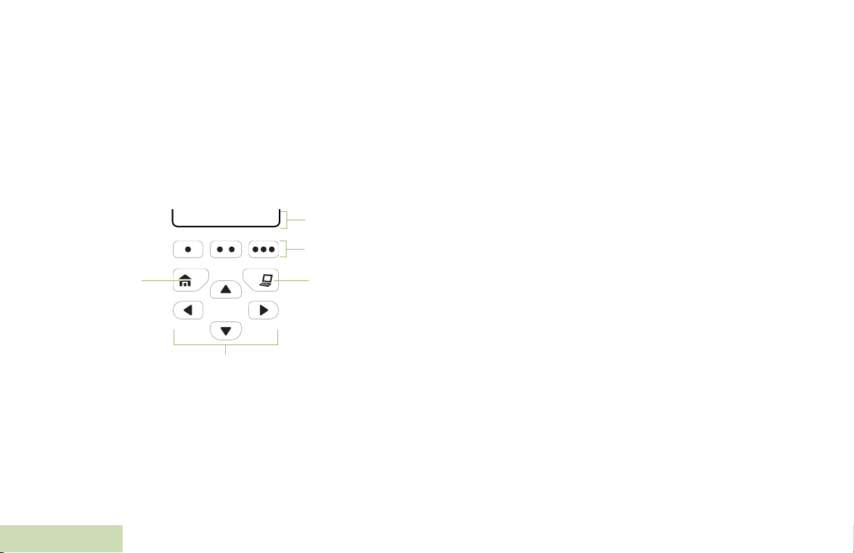
The Menu Select buttons access the menu entries of features.
Note: Check with your dealer or system administrator for the
list of features activated in your radio.
Your radio may be preprogrammed differently from the following
example, but the steps for selecting a channel may appear as
shown below:
• Press the Menu Select button ( | ) directly below Chan.
Mute | Chan | Zone
Home Button
4-Way Navigation Button
Softkeys
Menu Select
Buttons
Data Feature
Button
Identifying Radio Controls
Home Button
The H button returns you to the Home (default) screen. In most
cases, this is the current mode.
For selected radio features, the H button is also used to save
user-edited radio settings or information before returning you to
the Home screen.
Note: Some features do not require you to press
the Home screen. Refer to the individual feature
sections in this manual for further details on saving
user-edited radio settings or information.
H to go to
14
English
Page 31

Data Feature Button
Use this button to access data-related features, such as the
Text Messaging Service (TMS) feature screen.
4-Way Navigation Button
Use this button to scroll up, down, left or right.
Press and release one of the button to scroll from one entry to
the next one. Press and hold one of the button to have your
radio toggles through the list automatically (release the button
to stop).
Multi-Function Knob (MFK)
MFK is the on/off button of your radio. See Turning On the
Radio on page 7 for the procedure to power up and down your
radio.
In addition, there are programmable features available for MFK,
which are:
Mode Change – Turn MFK to scroll the channel or zone list.
Volume Change – Turn MFK to increase or decrease the
volume level of the speaker. Fast turn of MFK makes coarse
tuning of the volume level; slow turn of MFK makes fine tuning
of the volume level. The display shows the volume level and
bars to indicate the current level. The level of last selected
volume before your radio powers down remains the same when
the radio powers up.
The main display only shows the icon of secondary feature; the
main display does not show the icon of primary feature.
Your radio by default is set to use the primary feature. Short
presses of MFK toggle it to work on either the secondary or
primary feature.
The secondary feature has an inactivity timer. This timer starts
when the secondary feature is left idle. The radio returns to
primary feature when this timer expires.
If the MFK is set to operate only one feature besides On/Off the
radio, Volume Change should be the only feature applied to
MFK.
Consult your dealer or system administrator for the best option
available for MFK.
Identifying Radio Controls
English
15
Page 32
Push-To-Talk (PTT) Button
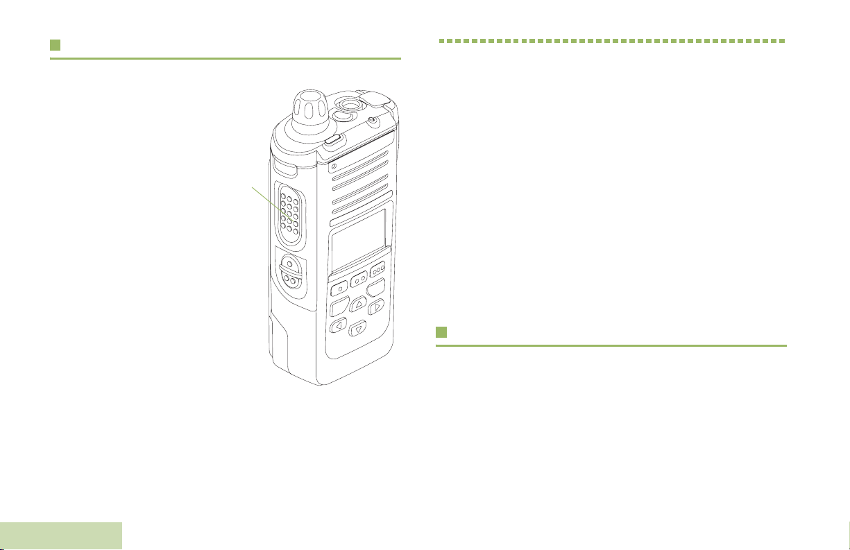
The PTT button on the side
of the radio serves two basic
purposes :
• While a call is in progress,
the PTT button allows
your radio to transmit to
other radios in the call.
Press and hold down PTT
button to talk. Release the
PTT button to listen.
The microphone is
activated when the PTT
button is pressed.
• While a call is not in
progress, the PTT button
is used to make a new
call. See Making a Radio
Call on page 37 for more
information.
Identifying Status Indicators
PTT
Button
Identifying Status Indicators
Your radio indicates its operational status through the following:
Status Icons . . . . . . . . . . . . . . . . . . . . . . . . . . . . . . . . . page 16
Text Messaging Service (TMS) Icons . . . . . . . . . . . . . page 19
Status Icons . . . . . . . . . . . . . . . . . . . . . . . . . . . . . . . page 19
TMS Menu Options . . . . . . . . . . . . . . . . . . . . . . . . . page 21
Call Type Icons . . . . . . . . . . . . . . . . . . . . . . . . . . . . . . page 21
Top Lightbar and LED Indicators . . . . . . . . . . . . . . . . . page 22
LED Indications . . . . . . . . . . . . . . . . . . . . . . . . . . . . page 23
Top Lightbar Indications . . . . . . . . . . . . . . . . . . . . . . page 23
Intelligent Lighting Indicators . . . . . . . . . . . . . . . . . . . . page 24
Alert Tones. . . . . . . . . . . . . . . . . . . . . . . . . . . . . . . . . . page 25
Phone Call Display and Alert Prompts. . . . . . . . . . . . . page 29
Status Icons
The 160 x 90 pixel front liquid crystal display (LCD) of the radio
shows radio status, text entries, and menu entries. The top
display row contain color icons that indicate radio operating
conditions.
16
English
Page 33

The following icons are for the front display screen unless
indicated otherwise.
Receiving
Radio is receiving a call or data.
Transmitting
Radio is transmitting a call or data.
Battery
For IMPRES battery operation only – the icon
shown indicates the charge remaining in the
battery.
For all battery operation – the icon blinks when
the battery is low.
Received Signal Strength Indicator (RSSI)
The number of bars displayed represents the
received signal strength for the current site, for
trunking only. The more stripes in the icon, the
stronger the signal.
Direct
O
Monitor (Carrier Squelch)
M
K
H
or .
• On = Radio is currently configured for direct
radio-to-radio communication (during
conventional operation only).
• Off = Radio is connected with other radios
through a repeater.
Selected channel is being monitored (during
conventional operation only).
In-Call User Alert
• On = The feature is enabled. Voice muting of
the affiliated trunking talkgroup or
selected conventional channel is
activated.
• Off = The feature is disabled. Voice muting of
the affiliated trunking talkgroup or
selected conventional channel is
deactivated.
Power Level
• L = Radio is set at Low power.
• H = Radio is set at High power.
Identifying Status Indicators
i
Scan
Radio is scanning a scan list.
17
English
Page 34
Priority Channel Scan
Location Signal
• Blinking dot = Radio detects activity on
• Steady dot = Radio detects activity on channel
Vote Scan Enabled
k
m
l
The vote scan feature is enabled.
Secure Operation
• On = Secure operation.
• Off = Clear operation.
• Blinking = Receiving an encrypted voice call.
AES Secure Operation
• On = AES Secure operation.
• Off = Clear operation.
• Blinking = Receiving an encrypted voice call.
Identifying Status Indicators
channel designated as
Priority-One.
designated as Priority-Two.
G
n
n
o
b
• On = Location feature is enabled, and location
signal is available.
• Off = Location feature is disabled.
• Blinking = Location feature is enabled, but no
location signal is available.
User Login Indicator (IP Packet Data)
• On = User is currently associated with your
radio.
• Off = User is currently not associated with your
radio.
• Blinking = Device registration or user
registration with the server failed
due to an invalid username or pin.
• Inverted = User successfully login to the
secured IP Packet Data.
Data Activity
Data activity is present.
Bluetooth On
Bluetooth is on and ready for bluetooth
connection.
18
English
Page 35
Bluetooth Connected
Bluetooth is currently connected to the external
bluetooth device.
MFK is in Mode Change feature
Turn the MFK to change the channel/zone.
Text Messaging Service (TMS) Icons
This feature allows you to send and receive text messages. See
Text Messaging Service (TMS) on page 66 for more
information.
Status Icons
Identifying Status Indicators
MFK is in Volume Change feature
Turn the MFK to turn the volume up or down.
The following icons appear on your radio’s display when you
send and receive text messages.
Inbox Full
The Inbox is full.
Message Sent
The text message is sent successfully.
Message Unsent
The text message cannot be sent.
Unread Message
• User receives a new message.
• The selected text message in the Inbox has not
been read.
19
English
Page 36
Read Message
Y
r
3/6
The selected text message in the Inbox has been
read.
Normal Message
User is composing a message with normal priority
and without a request for a reply.
Message Index
Indicates the index of the current message the
user is viewing.
Example: If the user is looking at the third
message out of a total of 6 messages in the Inbox
folder, the icon is displayed as the icon on the left
column.
Priority Status
• The “Priority” feature is toggled on before the
message is sent.
• Messages in the Inbox folder are flagged with
”Priority”.
Identifying Status Indicators
Request Reply
• The “Request Reply” feature is toggled on
before the message is sent.
• Messages in the Inbox folder are flagged with
“Request Reply”.
Priority Status and Request Reply
• User is composing a message with a priority
status and a request for a reply.
• Messages in the Inbox folder are flagged with
“Priority” and “Request Reply”.
20
English
Page 37
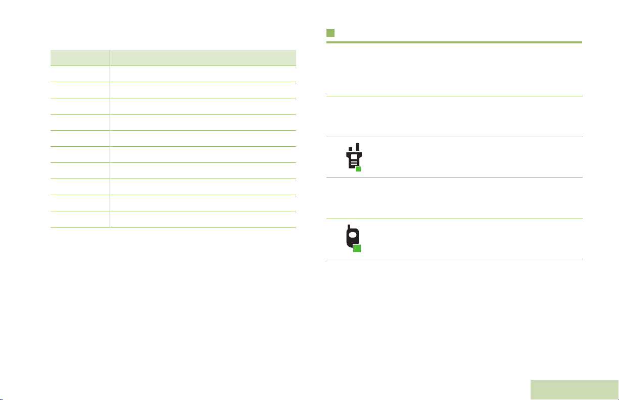
TMS Menu Options Call Type Icons
Menu Option Description/Function
Back Brings you back to the previous screen.
Clr Deletes all messages.
Del Deletes a message.
Exit Exits to the Home screen.
No Returns to the previous screen.
Optn Brings you to the Options main screen.
Rply Replies to a message.
Sel Selects the highlighted command.
Send Sends the message.
Yes Updates or saves a command.
The following icons appear on your radio’s main display, when
you make or receive a call, or view selected call lists, to indicate
the different call types associated with an alias or ID.
Radio number.
U
Radio number added to a Call List.
Mobile number.
?
Mobile number added to a Call List.
Identifying Status Indicators
English
21
Page 38
%
Landline phone number.
Landline phone number added to a Call List.
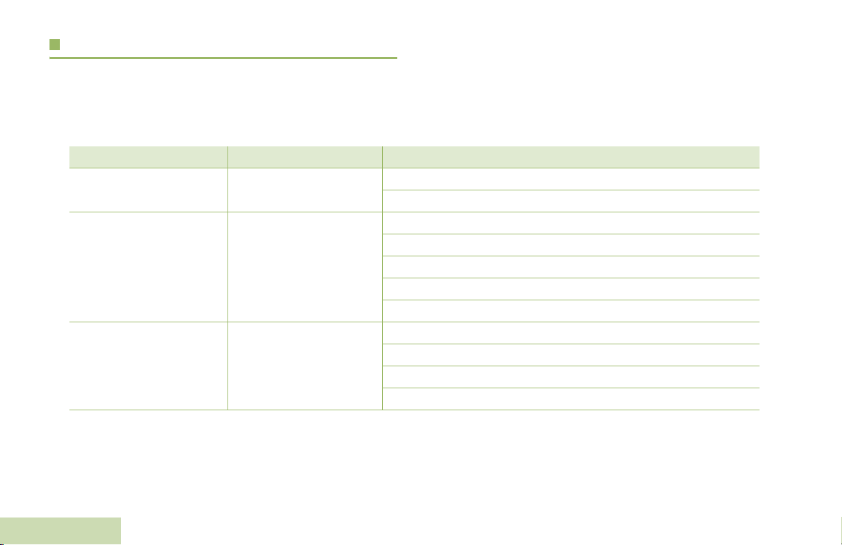
Top Lightbar and LED Indicators
The Top Lightbar and LED indicators show the operational
status of the radio.
LED
Identifying Status Indicators
22
English
Incoming call or data.
Outgoing call or data.
Incoming emergency call.
Top Lightbar
Page 39

LED Indications
Top Lightbar Indications
Solid red – Radio is transmitting.
Blinking red – Radio is transmitting at low battery condition.
Rapidly blinking red – Radio has failed the self test upon
powering up or encountered a fatal error.
Solid yellow (Conventional Only) – Channel is busy.
Blinking yellow – Radio is receiving a secured transmission.
Solid green – Radio is powering up, or is on a non-priority
channel while in the Scan List Programming mode.
Blinking green – Radio is receiving an individual or telephone
call, or is on a Priority-Two channel while in the Scan List
Programming mode.
Rapidly blinking green – Radio is on a Priority-One channel
while in the Scan List Programming mode.
Note: No LED indication when your radio receives a clear
(non-secured) transmission in trunking Mode.
The lightbar blinks green when the MFK is using the secondary
feature. See Multi-Function Knob (MFK) on page 15 to
understand the functionality of MFK.
The lightbar turn into solid color of orange, red or green
depending on the status of Intelligent Lighting. See Intelligent
Lighting Indicators on page 24 for different status of Intelligent
Lighting.
Identifying Status Indicators
English
23
Page 40
Intelligent Lighting Indicators
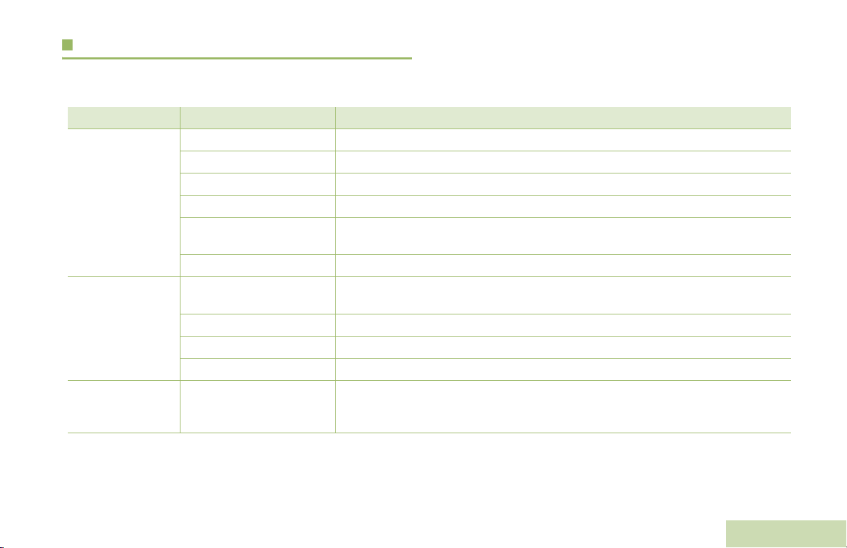
This feature temporary changes the color of the Top Lightbar and adds a color bar to the main display screen to help signal that a
radio event has occurred.
Note: This feature must be preprogrammed by a qualified radio technician.
Bar Color Notification When
Orange Emergency Alerts
Red Critical Alerts
Green Call Alerts
The radio initiates an emergency alarm or call.
The radio receives an emergency alarm or call.
The radio battery is low.
The radio is out of range.
The radio enters failsoft mode.
The radio is unable to establish a full connection with the system.
The radio is unable to authenticate or register with the system.
The radio receives a private call.
The radio receives a phone call.
The radio receives a call alert.
The radio receives a selective call.
Identifying Status Indicators
24
English
Page 41
Alert Tones
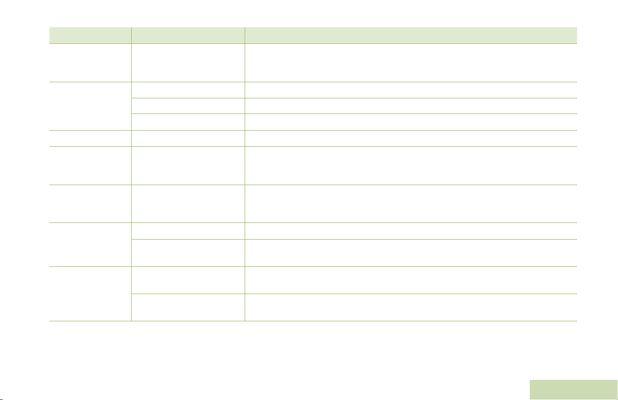
The radio uses alert tones to inform you of the radio’s condition. The following table lists these tones and when they occur.
You Hear Tone Name Heard
Radio Self Test Fail When radio fails its power-up self test.
Reject When an unauthorized request is made.
Short,
Low-Pitched
Tone
Long,
Low-Pitched
Tone
A Group of
Low-Pitched
Ton es
Time-Out Timer Warning Four seconds before time out.
No ACK Received When radio fails to receive an acknowledgment.
Individual Call
Warning Tone
Man Down Entry When radio initiates Man Down mode.
Time-Out Timer
Timed Out
Talk Prohibit/PTT Inhibit (When PTT button is pressed) transmissions are not allowed.
Out of Range (When PTT button is pressed) the radio is out of range of the system.
Invalid Mode When radio is on an unpreprogrammed channel.
Busy When system is busy.
When radio is in an individual call for greater than 6 seconds without any activity.
After time out.
Identifying Status Indicators
English
25
Page 42

You Hear Tone Name Heard
Short,
Medium-Pitched
Tone
Long,
Medium-Pitched
Tone
A Group of
Medium-Pitched
Ton es
Identifying Status Indicators
Valid Key-Press When a correct key is pressed.
Radio Self Test Pass When radio passes its power-up self test.
Clear Voice At beginning of a non-coded communication.
Priority Channel
Received
Emergency Alarm /Call
Entry
Central Echo When central controller has received a request from a radio.
Volume Set When volume is changed on a quiet channel.
Emergency Exit When exiting the emergency state.
Failsoft When the trunking system fails.
Automatic Call Back When voice channel is available from previous request.
Talk Permit (When PTT button is pressed) verifying system accepting transmissions.
Keyfail When encryption key has been lost.
Console Acknowledge When status, emergency alarm, or reprogram request ACK is received.
Received Individual Call When Call Alert or Private Call is received.
Call Alert Sent When Call Alert is received by the target radio.
Site Trunking When a SmartZone trunking system fails.
When activity on a priority channel is received.
When entering the emergency state.
26
English
Page 43
You Hear Tone Name Heard
Short,
High-Pitched
Tone (Chirp)
Ringing
Gurgle Dynamic Regrouping (When the PTT button is pressed) a dynamic ID has been received.
Unique,
Low-Pitched
Chirp
Unique,
High-Pitched
Chirp
Doh-Sol
Sol-Doh
Low-Battery Chirp When battery is below preset threshold value.
Fast Ringing When system is searching for target of Private Call.
Enhanced Call Sent When waiting for target of Private Call to answer the call.
Phone Call Received When a land-to-mobile phone call is received.
New Message When a new message is received.
Priority Status When a priority message is received.
Enhanced Zone Bank Up When EZB Up button is pressed to scroll the Enhance Zone Bank up.
MFK Enters Secondary
Feature
MFK Exits Secondary
Feature
Enhanced Zone Bank
Down
When MFK is toggled to secondary feature.
When MFK is toggled to exit secondary feature and return to primary feature.
When EZB Down button is pressed to scroll the Enhance Zone Bank down.
Identifying Status Indicators
English
27
Page 44
You Hear Tone Name Heard
Incremental-
Pitched Tone
DecrementalPitched Tone
A Group of Very
High-Pitched
Ton es
Identifying Status Indicators
Bluetooth Paired When Bluetooth accessory is paired with the radio.
Bluetooth Connected When Bluetooth accessory is connected to the radio.
Bluetooth Unpaired When Bluetooth accessory is unpaired from the radio.
Bluetooth Disconnected When Bluetooth accessory is disconnected from the radio.
Man Down Continuous
Tone
When radio is in Man Down mode and prepares to transmit Emergency Alarm
when the timer of this alarm ends.
28
English
Page 45
Phone Call Display and Alert Prompts
The following appears on the radio’s display when you make and receive Phone calls. The radio also uses alert tones to indicate the
current status.
You Hear You S e e When Notes
A Long
Tone
A Busy
Tone
–
A High-
Pitched
Tone
No phone
Phone busy The phone system is busy. Press
Phone busy When a channel is not available. The radio automatically connects when a channel opens.
No
acknowledge
– When you release the PTT button.
You press the PTT button and the
phone system is not available.
The call is not acknowledged. Press
H to hang up. The radio returns to the Home screen.
Press
H to exit the phone mode and try your call later.
H to hang up. The radio returns to the Home screen.
The radio indicates to the landline party that he or she may begin
talking.
Identifying Status Indicators
English
29
Page 46
General Radio Operation
Once you understand how your APX 4000 Portable is
configured, you are ready to use your radio.
Selecting a Zone
A zone is a group of channels.
Use this navigation guide to familiarize yourself with the basic
Call features:
Selecting a Zone . . . . . . . . . . . . . . . . . . . . . . . . . . . . . page 30
Selecting a Radio Channel . . . . . . . . . . . . . . . . . . . . . page 31
Receiving and Responding to a Radio Call. . . . . . . . . page 34
Making a Radio Call . . . . . . . . . . . . . . . . . . . . . . . . . . page 37
Repeater or Direct Operation . . . . . . . . . . . . . . . . . . . page 40
Monitoring Features . . . . . . . . . . . . . . . . . . . . . . . . . . page 40
General Radio Operation
30
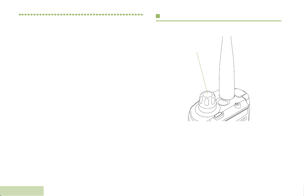
MFK
Use the following procedure to select a zone.
Note: Your radio must be preprogrammed to allow you to use
this feature.
If Mode Change is secondary feature of the MFK, see
Multi-Function Knob (MFK) on page 15 to toggle the
function of MFK.
English
Page 47
Procedure:
Turn the preprogrammed Zone Change MFK to the required
zone and proceed to Step 3.
OR
Follow the procedure below.
1 < or > to Zone.
2 Press the Menu Select button directly below Zone.
3 U or D to the required zone.
4 Press the Menu Select button directly below Sel to confirm
the displayed zone.
5 Press the PTT button to transmit on the displayed zone
channel.
OR
Follow the procedure below.
Selecting a Radio Channel
A channel is a group of radio characteristics, such as transmit/
receive frequency pairs.
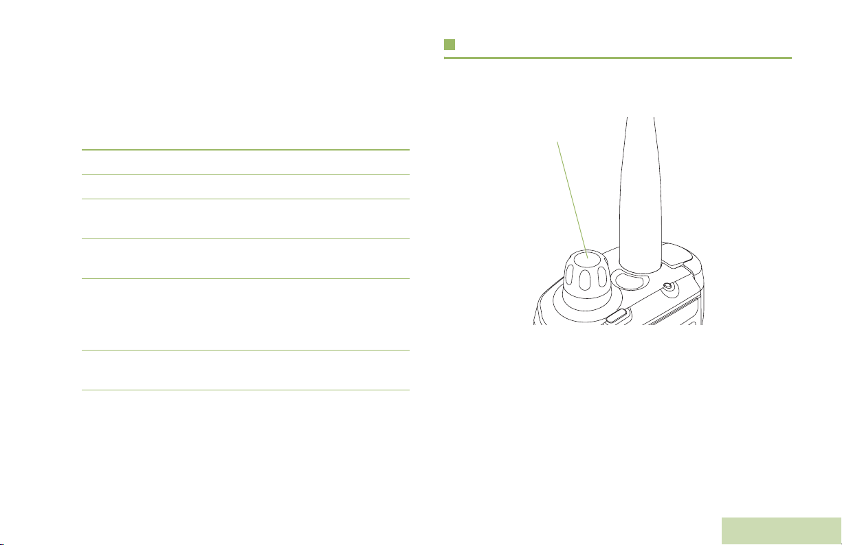
MFK
General Radio Operation
1 < or > to ZnUp or ZnDn.
2 Press and hold the Menu Select button directly below ZnUp
or ZnDn until the required zone appears.
Note: Positions of ZnUp and ZnDn on the display may differ
each time you release the Menu Select button. Read
carefully before you press.
Use the following procedure to select a channel.
Note: Your radio must be preprogrammed to allow you to use
this feature. If you select a channel that is not within the
preprogrammed band, the radio indicates that it is on
an unsupported frequency with both audio and visual
warnings.
Consult a qualified radio technician for the right choice
between the following methods.
31
English
Page 48

If Mode Change is secondary feature of MFK, see
Multi-Function Knob (MFK) on page 15 to toggle the
function of MFK.
Procedure:
Turn the preprogrammed MFK to the desired channel.
OR
Follow the procedure below.
OR
Follow the procedure below.
1 < or > to ChUp or ChDn.
2 Press the Menu Select button directly below ChUpor ChDn.
3 Press the PTT button to transmit on the displayed zone and
channel.
1 < or > to Chan.
2 Press the Menu Select button directly below Chan.
3 U or D to the required channel.
4 Press the Menu Select button directly below Sel to confirm
the selected channel.
5 Press the PTT button to transmit on the displayed zone
channel.
General Radio Operation
32
English
Note: Positions of ChUp and ChDn on the display may differ
each time you release the Menu Select button. Read
carefully before you press.
Page 49

Using Mode Select Feature
Saving a Zone and Channel to a Softkey
Mode Select allows a long press to save the radio’s current
zone and channel to a programmable button, keypad button or
a softkey; then once programmed, the short-press of that button
or softkey jumps the transmission to the saved zone and
channel.
There are two methods to save the selected zone and channel:
• Softkeys
• Programmable buttons and keypad buttons (digit 0 to 9)
Note: Your radio must be preprogrammed to allow you to use
this feature.
Five softkeys are available for you to save the frequent used
zone and channel.
Procedure:
1 Toggle your zone and channel to the required zone and
channel.
2 < or > to MS1, MS2 ... or MS5.
3 Press and hold the Menu Select button directly below the
softkey.
4 You hear a short, medium-pitched tone when the zone and
channel is saved.
Note: To change the programmed zone and channel, repeat
this procedure.
Short press of the programmed softkey changes your current
transmission to the zone and channel programmed in this
softkey.
General Radio Operation
English
33
Page 50
Saving a Zone and Channel to a Button
Receiving and Responding to a Radio Call
All the programmable buttons and keypad digit 0 to 9 buttons
allow you to save the frequent used zone and channel.
Procedure:
1 Toggle your zone and channel to the required zone and
channel.
2 Press and hold the digit button you desire to program.
3 You hear a short, medium-pitched tone when the zone and
channel is saved.
Note: Repeat this procedure to change the zone and channel
of the programmed button.
Short press of the programmed button changes your current
transmission to the zone and channel programmed in this
button.
General Radio Operation
34
Once you have selected the required channel and/or zone, you
can proceed to receive and respond to calls.
LED Indicator
The LED lights up solid red while the radio is transmitting. In
conventional mode, the LED lights up solid yellow when the
radio is receiving a transmission. In trunking mode, there is no
LED indication when the radio receives a transmission.
If the radio is receiving a secure transmission, the LED blinks
yellow.
English
Page 51

Receiving and Responding to a Talkgroup Call
To receive a call from a group of users, the radio must be
configured as part of that talkgroup.
Procedure:
When you receive a talkgroup call (while on the Home screen),
depending on how your radio is preprogrammed:
1 ASTRO Conventional Only:
The LED lights up solid yellow. The display shows the
talkgroup alias or ID, and the caller alias or ID.
OR
Trunking Only:
The display shows the caller alias or ID.
2 Hold the radio vertically 1 to 2 inches (2.5 to 5.0 cm) from
your mouth.
3 Press the PTT button to respond to the call. The LED lights
up solid red.
4 Release the PTT button to listen.
Receiving and Responding to a Private Call
(Trunking Only)
A Private Call is a call from an individual radio to another
individual radio.
These one-to-one calls between two radios are not heard by
others in the current talkgroup. The calling radio automatically
verifies that the receiving radio is active on the system and can
display the caller ID.
Note: The radio automatically exits the feature, if the feature
inactivity timer is enabled, when the radio is left idle
and the timer expires. You will hear the Menu Inactive
Exit Tone upon feature exit.
Procedure:
When you receive a Private Call:
1 You hear two alert tones and the LED blinks green. The
display shows Call received and the call received icon
blinks.
2 Press the Menu Select button directly below Resp.
See Making a Talkgroup Call on page 37 for details on making
a Talkgroup Call.
OR
Press the Call Response button within 20 seconds after the
call indicators begin.
General Radio Operation
3 During the call, the display shows the caller alias (name), if it
is in the call list.
OR
English
35
Page 52

During the call, the display shows the caller ID (number), if
the caller’s name is not in the call list.
4 Press and hold the PTT button to talk. Release the PTT
button to listen.
5 Press H or the Call Response button to hang up and
return to the Home screen.
Procedure:
Use the preprogrammed Call Response button to answer a
Telephone Call:
1 You hear a telephone-type ringing and the LED blinks green.
The backlight of the screen and the bar turns green. The
display shows Phone Call and the call received icon blinks.
See Making a Private Call (Trunking Only) on page 37 for
details on making a Private Call.
Receiving and Responding to a Telephone Call
(Trunking Only)
This feature allows you to receive calls similar to standard
phone calls from a landline phone.
Note: The radio automatically exits the feature, if the feature
inactivity timer is enabled, when the radio is left idle
and the timer expires. You will hear the Menu Inactive
Exit Tone upon feature exit.
General Radio Operation
36
English
2 Press the Call Response button within 20 seconds after the
call indicators begin.
3 Press and hold the PTT button to talk. Release the PTT
button to listen.
4 Press H or the Call Response button to hang up and
return to the Home screen.
See Making a Telephone Call (Trunking Only) on page 39 for
details on making a Telephone Call.
Page 53

Making a Radio Call
You can select a zone, channel, subscriber ID, or talkgroup by
using:
• MFK preprogrammed with channel or zone change
• A preprogrammed One Touch Call button
• The Contacts list
3 Press the PTT button to make the call.
4 ASTRO Conventional Only:
The LED lights up solid red. The display shows the
talkgroup alias or ID.
OR
Trunking Only:
The LED lights up solid red.
5 Speak clearly into the microphone.
General Radio Operation
Note: The radio automatically exits the feature, if the feature
inactivity timer is enabled, when the radio is left idle
and the timer expires. You will hear the Menu Inactive
Exit Tone upon feature exit.
Making a Talkgroup Call
To make a call to a group of users, your radio must be
configured as part of that talkgroup.
Procedure:
1 Turn the MFK to select the channel with the desired
talkgroup.
2 Hold the radio vertically 1 to 2 inches (2.5 to 5.0 cm) from
your mouth.
6 Release the PTT button to listen.
Making a Private Call (Trunking Only)
Procedure:
Press the preprogrammed Quick Access (One-Touch) Private
Call button to dial the preprogrammed ID (number) and proceed
to Step 5.
OR
Follow the procedure below.
1 < or > to Call.
2 Press the Menu Select button directly below Call. The
display shows the last transmitted or received ID.
English
37
Page 54

3 Press the Menu Select button directly below Cnts to scroll
through and select the required ID.
OR
Press the Menu Select button directly below LNum to go to
the last number dialed.
OR
U or D to the required ID.
4 Press the PTT button to start the Private Call.
5 The display shows Calling... <Number>.
6 Hold the radio vertically 1 to 2 inches (2.5 to 5.0 cm) from
your mouth.
7 When you are connected, the display shows the ID of the
target radio. Press and hold the PTT button to talk. Release
the PTT button to listen.
OR
If no acknowledgment is received, the display shows No
acknowledge.
8 Press H to return to the Home screen.
General Radio Operation
Making an Enhanced Private Call (Trunking Only)
This feature allows you to send an individual Call Alert page if
there is no answer from the target radio. See Sending a Call
Alert Page on page 55 for more information.
Note: Your radio must be preprogrammed to allow you to use
this feature.
Procedure:
Press the preprogrammed Quick Access (One-Touch)
Enhanced Private Call button to dial the preprogrammed ID
and proceed to Step 5.
OR
Follow the procedure below.
1 < or > to Call.
2 Press the Menu Select button directly below Call. The
display shows the last transmitted or received ID.
3 Press the Menu Select button directly below Cnts to scroll
through and select the required ID.
OR
Press the Menu Select button directly below LNum to go to
the last number dialed.
OR
U or D to the required ID.
4 Press the PTT button to start the Private Call.
38
English
Page 55

5 The display shows Calling... <Number>.
6 Hold the radio vertically 1 to 2 inches (2.5 to 5.0 cm) from
your mouth.
7 When you are connected, the display shows the ID of the
target radio. Press and hold the PTT button to talk. Release
the PTT button to listen.
OR
If no acknowledgment is received, the display shows No
acknowledge.
OR
If the target radio does not respond before the time out, the
display shows No answer.
8 Press H to return to the Home screen.
Making a Telephone Call (Trunking Only)
This feature allows you to make calls similar to standard phone
calls to a mobile or landline phone.
Procedure:
Press the preprogrammed Quick Access (One-Touch) Phone
Call button to dial the preprogrammed phone number and
proceed to Step 5.
OR
Follow the procedure below.
2 Press the Menu Select button directly below Phon. The
display shows the last transmitted phone number.
3 Press the Menu Select button directly below Cnts to scroll
through and select the required ID.
OR
Press the Menu Select button directly below LNum to go to
the last number dialed.
OR
U or D to the required phone number.
4 Press and release the PTT button to dial the phone number.
5 Hold the radio vertically 1 to 2 inches (2.5 to 5.0 cm) from
your mouth.
6 When your call is answered, press the PTT button to talk.
Release the PTT button to listen.
7 Press H to return to the Home screen.
See Phone Call Display and Alert Prompts on page 29 for
more information if your call is NOT answered.
General Radio Operation
1 < or > to Phon.
39
English
Page 56

Repeater or Direct Operation
Monitoring Features
The REPEATER operation increases the radio’s range by
connecting with other radios through a repeater. The transmit
and receive frequencies are different.
The DIRECT or “talkaround operation” allows you to bypass the
repeater and connect directly to another radio. The transmit and
receive frequencies are the same.
Procedure:
Press the preprogrammed Repeater/Direct button to toggle
between talkaround and repeater modes.
OR
Follow the procedure below.
1 < or > to Dir.
2 Press the Menu Select button directly below Dir.
3 The display shows Repeater mode if the radio is currently
in Repeater mode.
OR
The display shows Direct mode and the Talkaround icon if
the radio is currently in Direct mode (during conventional
operation only).
General Radio Operation
Radio users who switch from analog to digital radios often
assume that the lack of static on a digital channel is an
indication that the radio is not working properly. This is not the
case.
This digital technology quiets the transmission by removing the “
noise” from the signal and allows only the clear voice or data
information to be heard.
Use the Monitor feature to make sure a channel is clear before
transmitting.
40
English
Page 57

Monitoring a Channel
Procedure:
Press the preprogrammed Monitor button and proceed to
Step 3.
OR
Follow the procedure below.
1 Select the desired zone and channel.
2 Listen for a transmission.
3 Adjust the Vo l u m e Change MFK if necessary.
4 Press and hold the PTT button to transmit. The LED lights
up solid red.
5 Release the PTT button to receive (listen).
The Carrier Squelch indicator appears on the display when you
monitor a channel via the preprogrammed Monitor button.
Conventional Mode Operation
Your radio may be preprogrammed to receive Private-Line
(PL) calls.
Procedure:
®
1 Momentarily press the Monitor button to listen for activity.
The Carrier Squelch indicator appears on the display.
2 Press and hold the Monitor button to set continuous
monitor operation. The duration of the button press is
programmable.
3 Press the Monitor button again, or the PTT button, to return
to the original squelch setting.
If you try to transmit on a receive-only channel, you hear an
invalid tone until you release the PTT button.
General Radio Operation
English
41
Page 58
Advanced Features
Advanced Call Features
Use this navigation guide to learn more about advanced
features available with your radio:
Advanced Call Features . . . . . . . . . . . . . . . . . . . . . . . page 42
Contacts . . . . . . . . . . . . . . . . . . . . . . . . . . . . . . . . . . . page 48
Scan Lists . . . . . . . . . . . . . . . . . . . . . . . . . . . . . . . . . . page 51
Scan . . . . . . . . . . . . . . . . . . . . . . . . . . . . . . . . . . . . . . page 53
Call Alert Paging . . . . . . . . . . . . . . . . . . . . . . . . . . . . . page 54
Emergency Operation . . . . . . . . . . . . . . . . . . . . . . . . . page 56
Man Down. . . . . . . . . . . . . . . . . . . . . . . . . . . . . . . . . . page 59
Automatic Registration Service (ARS) . . . . . . . . . . . . page 64
Text Messaging Service (TMS) . . . . . . . . . . . . . . . . . . page 66
Secure Operations . . . . . . . . . . . . . . . . . . . . . . . . . . . page 74
The Global Positioning System (GPS) . . . . . . . . . . . . page 79
Trunking System Controls. . . . . . . . . . . . . . . . . . . . . . page 85
Mission Critical Wireless - Bluetooth® - . . . . . . . . . . . page 87
Programming Over Project 25 (POP 25) (ASTRO 25 and
ASTRO Conventional) . . . . . . . . . . . . . . . . . . . . . . . page 95
Utilities. . . . . . . . . . . . . . . . . . . . . . . . . . . . . . . . . . . . . page 96
Advanced Features
Receiving and Making a Selective Call (ASTRO
Conventional Only)
This feature allows you to receive a call from or to call a specific
individual. It is intended to provide privacy and to eliminate the
annoyance of having to listen to conversations that are of no
interest to you.
Receiving a Selective Call
Procedure:
1 When you receive a Selective Call, the call received icons
blinks and the display shows Call received.
You hear two alert tones,
the LED lights up solid yellow to indicate the transmitting
radio is still sending signal.
OR
the LED blinks solid green once to indicate the transmitting
radio is pending to receive signal.
2 The speaker unmutes.
3 Hold the radio vertically 1 to 2 inches (2.5 to 5.0 cm) from
your mouth.
4 Press and hold the PTT button to talk. Release the PTT
button to listen.
42
English
Page 59

Making a Selective Call
Procedure:
Press the preprogrammed Quick Access (One-Touch)
Selective Call button to dial the preprogrammed ID and
proceed to Step 4.
OR
Follow the procedure below.
1 < or > to Call.
2 Press the Menu Select button directly below Call. The
display shows the last transmitted or received ID.
3 Press the Menu Select button directly below Cnts to scroll
through and select the required ID.
OR
Press the Menu Select button directly below LNum to go to
the last number dialed.
OR
U or D to the required ID.
OR
Use the keypad to enter the required ID.
4 Hold the radio vertically 1 to 2 inches (2.5 to 5.0 cm) from
your mouth.
5 Press and hold the PTT button to start the Selective Call.
The display shows the ID of the target radio.
6 Release the PTT button to listen.
7 Press H to hang up and return to the Home screen.
Using the Talkgroup Call Feature (Conventional
Operation Only)
This feature allows you to define a group of conventional
system users so that they can share the use of a conventional
channel.
Note: Encryption keys are associated to talkgroups. When
talkgroups are associated, encryption keys are
changed by changing the active talkgroup. See Secure
Operations on page 74 for more information.
Selecting a Talkgroup
Procedure:
1 < or > to Tgrp.
2 Press the Menu Select button directly below Tgrp. The
display shows the last talkgroup that was selected and
stored, Sel and Exit.
Advanced Features
English
43
Page 60

3 U or D to Preset for the preset preprogrammed talkgroup.
OR
U or D to the required talkgroup.
4 Press the Menu Select button directly below Sel to save the
currently selected talkgroup and return to the Home screen.
5 If the encryption key associated to the new talkgroup is
erased, you hear a momentary key fail tone and the display
shows Key fail.
OR
If the encryption key that is associated to the new talkgroup
is not allowed, you hear a momentary key fail tone and the
display shows Illegal key.
6 Press H to return to the Home screen.
Advanced Features
Sending a Status Call
This feature allows you to send data calls to the dispatcher
about a predefined status.
Each status can have up to a 14-character name. A maximum
of sixteen status conditions is possible.
Note: The radio automatically exits the feature, if the feature
inactivity timer is enabled, when the radio is left idle
and the timer expires. You will hear the Menu Inactive
Exit Tone upon feature exit.
Procedure:
Press the preprogrammed Status button and proceed to
Step 3.
OR
Follow the procedure below.
1 < or > to Sts.
2 Press the Menu Select button directly below Sts.
3 The display shows the last acknowledged status call, or the
first status in the list.
4 U or D to the required status.
OR
Use the keypad to enter a number corresponding to the
location in the status list.
5 Press the PTT button to send the status.
44
English
Page 61

6 When the dispatcher acknowledges, you hear four tones
and the display shows Ack received. The radio returns to
normal dispatch operation.
OR
If no acknowledgment is received, you hear a low-pitched
tone and the display shows No acknowledge.
7 Press H to return to the Home screen.
No traffic is heard on trunked channels while Status Call is
selected. If the radio detects no Status Call activity for six
seconds, you will hear an alert tone until you press
PTT button.
H or the
Using the Dynamic Regrouping Feature (Trunking
Only)
This feature allows the dispatcher to temporarily reassign
selected radios to a particular channel where they can
communicate with each other. This feature is typically used
during special operations and is enabled by a qualified radio
technician.
You will not notice whether your radio has this feature enabled
until a dynamic regrouping command is sent by the dispatcher.
Note: If you try to access a zone or channel that has been
reserved by the dispatcher as a dynamically regrouped
mode for other users, you will hear an invalid tone.
Procedure:
1 When your radio is dynamically regrouped, it automatically
switches to the dynamically regrouped channel. You hear a
“gurgle” tone and the display shows the dynamically
regrouped channel’s name.
2 Press the PTT button to talk. Release PTT button to listen.
When the dispatcher cancels dynamic regrouping, the radio
automatically returns to the zone and channel that you were
using before the radio was dynamically regrouped.
Advanced Features
English
45
Page 62

Requesting a Reprogram (Trunking Only)
This feature allows you to notify the dispatcher when you want a
new dynamic regrouping assignment.
Classifying Regrouped Radios
The dispatcher can classify regrouped radios into either of two
categories: Select Enabled or Select Disabled.
Procedure:
Press the preprogrammed Reprogram Request button to send
reprogram request to the dispatcher and proceed to Step 3.
OR
Follow the procedure below.
1 < or > to Rpgm.
2 Press the Menu Select button directly below Rpgm to send
reprogram request to the dispatcher.
3 The display shows Reprgrm rqst and Please wait.
4 If you hear four beeps, the dispatcher has acknowledged the
reprogram request. The display shows Ack received and
the radio returns to the Home screen.
OR
If the dispatcher does not acknowledge the reprogram
request within six seconds, you hear a low-pitched alert tone
and the display shows No acknowledge.
Try again or press H to cancel and return to the Home
screen.
Advanced Features
46
• Select-enabled radios are free to change to any available
channel, including the dynamic-regrouping channel, once the
user has selected the dynamic-regrouping position.
• Select-disabled radios cannot change channels while
dynamically regrouped. The dispatcher has forced the radio
to remain on the dynamic-regrouping channel.
The Scan or Private Call feature cannot be selected while your
radio is Select Disabled.
Using Dynamic Zone Programming (DZP)
Note: Your radio must be preprogrammed to allow you to use
this feature.
This feature works on the condition at least one zone
in the radio must be a non-dynamic zone.
This feature provides one or more Dynamic Zones to store the
frequent used channels be it conventional or trunking. These
dynamic channels are saved from pre-existing (non-dynamic)
channels in the radio. This saves the time and effort from the
regular navigation around the working zones and channels.
User can also delete or update the list in the Dynamic Zone.
English
Page 63

Entering the Dynamic Zone to Select a Dynamic
Channel
Procedure:
1 < or > to Zone.
2 Press the Menu Select button directly below Zone. The
display shows the Zone screen.
3 U or D to <Dynamic Zone Channels>.
4 Press the Menu Select button below Sel. The display
returns to Home screen with the selected <Dynamic Zone
Channels> shown on the screen.
OR
Press the Menu Select button below Exit. The display
returns to Home screen without any changes.
Saving a Channel in the Dynamic Zone from List
Selection
With the radio in Dynamic Zone, follow the procedure below.
Procedure:
1 < or > to ZnPr. Press the Menu Select button directly below
ZnPr to enter Program Zone screen.
2 Press the Menu Select button directly below Edit. The
display shows Search Options screen.
3 U or D to List Selecton. Press the Menu Select button
directly below Sel. The display shows Select Zone screen.
4 U or D to the required zone. Press the Menu Select button
directly below Sel. The display shows Select Chan screen.
5 U or D to the required channel. Press the Menu Select
button directly below Sel. The display shows Channel
updated.
6 Press the Menu Select button directly below Exit to return
to Home screen.
Advanced Features
English
47
Page 64

Deleting a Channel in the Dynamic Zone
With the radio in Dynamic Zone, follow the procedure below.
Procedure:
1 < or > to ZnPr. Press the Menu Select button directly below
ZnPr to enter Program Zone screen.
2 The display shows the dynamic channels list.
3 U or D to the saved dynamic channel. Press the Menu
Select button directly below Del. The display shows
Channel deleted.
4 Press the Menu Select button below Exit to return to Home
screen.
5 The Home screen shows <Dynamic Zone Channels>.
OR
The Home screen shows <Zone Name>+“Blank” if the
channel deleted is the Home channel.
Advanced Features
Contacts
This feature provides “address-book” capabilities on your radio.
Each entry corresponds to an alias (name) or ID (number) that
you use to initiate a call.
Contact entries are alphabetically sorted according to entry
alias. Each alias can have up to five IDs of different call types
associated with it.
Additionally, each entry, depending on context (conventional,
trunking, or phone), associates with one or more of the four
types of calls: Phone Call, Selective Call, Private Call, or Call
Alert.
Each entry within Contacts displays the following information:
• Call Alias (Name)
• Call ID (Number)
• Call Type (Icon)
• WACN ID (Astro 25 Trunking IDs only)
• System ID
Note: Your radio must be preprogrammed to allow you to
add, edit, or delete the contact entries.
48
English
Page 65

Your radio also supports a maximum of 50 call lists. Each list
can store up to 100 IDs (numbers).
Note: Your radio is preprogrammed with a number of
contacts per Call Lists. Check with your dealer or
system administrator for more information.
The radio automatically exits the feature, if the feature
inactivity timer is enabled, when the radio is left idle
and the timer expires. You will hear the Menu Inactive
Exit Tone upon feature exit.
Making a Private Call from Contacts
Note: Your radio must be preprogrammed to allow you to use
this feature.
Procedure:
Use the Options Menu.
1 < or > to Cnts.
2 Press the Menu Select button directly below Cnts. The
entries are alphabetically sorted.
3 U or D to the required subscriber alias.
4 Press the Menu Select button directly below Optn.
5 U or D to Call and press the Menu Select button directly
below Sel.
6 U or D to select the call type.
7 Hold the radio vertically 1 to 2 inches (2.5 to 5.0 cm) from
your mouth.
8 Press the PTT button to initiate the call. During the call, the
display shows the subscriber alias.
9 Press and hold the PTT button to talk. The LED lights up
solid red.
OR
Release the PTT button to listen.
10 If there is no voice activity for a preprogrammed period of
time, the call ends.
OR
The call ends when it reaches the maximum ring time.
Advanced Features
English
49
Page 66

Adding a Contact to a Call List
Procedure:
1 < or > to Cnts.
Removing a Contact from a Call List
Procedure:
1 < or > to Cnts.
2 Press the Menu Select button directly below Cnts. The
entries are alphabetically sorted.
3 U or D to the entry you want to add to a call list and press
the Menu Select button directly below Optn.
4 U or D to Add to CallLst and press the Menu Select button
directly below Sel.
5 U or D to the required Call List and press the Menu Select
button directly below Add.
OR
U or D to Cncl to return to the main display for Contacts.
6 The display momentarily shows Please wait before
showing <Entry> added, confirming the addition of the
contact to the list.
7 The radio returns to the main display for Contacts.
Advanced Features
50
2 Press the Menu Select button directly below Cnts. The
entries are alphabetically sorted.
3 U or D to the entry you want to remove from a call list and
press the Menu Select button directly below Optn.
4 U or D to Rm frm CallLst and press the Menu Select button
directly below Sel.
5 The display shows <Entry> remove?.
6 Press the Menu Select button directly below Yes to remove
the entry from the Call List.
OR
Press the Menu Select button directly below No to return to
the main display for Contacts.
7 The display momentarily shows Please wait before
showing <Entry> removed, confirming the removal of the
contact from the list.
8 The radio returns to the main display for Contacts.
English
Page 67

Scan Lists
Scan lists are created and assigned to individual channels/
groups. Your radio scans for voice activity by cycling through the
channel/group sequence specified in the scan list for the current
channel/group.
Your radio supports different types of Scan Lists:
• Trunking Priority Monitor Scan List
• Conventional Scan List
• Talkgroup Scan List
Please refer to a qualified radio technician for the maximum
number of Scan Lists can be programmed in your radio. These
lists must be preprogrammed by a qualified radio technician.
Viewing a Scan List
Procedure:
1 < or > to ScnL.
2 Press the Menu Select button directly below ScnL.
3 U or D to view the members on the list.
4 Press H to exit the current display and return to the Home
screen.
Editing the Scan List
This feature lets you change scan list members and priorities.
Procedure:
Long press the preprogrammed Scan List Programming
button (side button) and proceed to Step 3.
OR
Follow the procedure below.
1 < or > to ScnL.
2 Press the Menu Select button directly below ScnL. The
display shows the lists that can be changed.
3 U or D to the entry you want to edit.
4 Press the Menu Select button directly below Sel to add and/
or change the priority of the currently displayed channel in
the scan list.
OR
Press the Menu Select button directly below Del to delete
the currently displayed channel from the scan list.
OR
Press the Menu Select button directly below Rcl to view the
next member of the scan list.
5 U or D to select more channels to be added or deleted.
OR
Use the MFK to select additional channels to be added or
deleted.
Advanced Features
English
51
Page 68

6 Press H to exit scan list programming and return to the
Home screen.
See Viewing and Changing the Priority Status on page 52 for
more information on how to add and/or change the priority of
the currently displayed channel in the scan list.
Changing the Scan List Status
Procedure:
1 Long press the preprogrammed Scan List Programming
button (side button).
2 The display shows the programming mode icon and the first
list member.
3 U or D to the member you want to edit.
4 Press the Select button once to add the currently displayed
channel to the scan list.
OR
Press the Select button one or more times to change the
scan list status icon of the currently displayed channel.
5 U or D to select more list members whose scan status you
want to change.
OR
Advanced Features
Use the MFK to select another scan list member.
6 Press H to exit scan list programming and return to the
Home screen.
52
Viewing and Changing the Priority Status
Procedure:
1 Below the Sel, Del, and Rcl screen, press the Menu Select
button directly below Sel to view and/or change the priority
status of the currently displayed channel.
OR
Below the Sel, Del, and Rcl screen, press the Select button
one or more times to view and/or change the scan list status
icon of the currently displayed channel.
2 A Scan icon indicates that the current channel is in the scan
list as a non-priority channel. The LED lights up solid green.
OR
A Priority-Two Channel Scan icon indicates that the current
channel is in the scan list as the Priority-Two channel. The
LED blinks green.
OR
A Priority-One Channel Scan icon indicates that the current
channel is in the scan list as the Priority-One channel. The
LED rapidly blinks green. You hear all traffic on the PriorityOne channel, regardless of traffic on non-priority channels.
OR
No icon indicates that the current channel is deleted from
the scan list.
English
Page 69

Scan
This feature allows you to monitor traffic on different channels
by scanning a preprogrammed list of channels.
Turning Scan On or Off
Procedure:
Press the preprogrammed Scan button to start or stop scan.
OR
Follow the procedure below.
1 < or > to Scan.
2 Press the Menu Select button directly below Scan.
3 The display shows Scan off if scan is disabled. Press the
Menu Select button directly below Scan to enable scan.
OR
The display shows Scan on and the scan status icon if scan
is enabled. Press the Menu Select button directly below
Scan to disable scan.
4 The radio returns to the Home screen.
Making a Dynamic Priority Change (Conventional
Scan Only)
While the radio is scanning, the dynamic priority change feature
allows you to temporarily change any channel in a scan list
(except for the Priority-One channel) to the Priority-Two
channel.
This change remains in effect until scan is turned off. Scan then
reverts to the preprogrammed (original) setting.
Procedure:
1 When the radio locks onto the channel designated as the
new Priority-Two channel, press the preprogrammed
Dynamic Priority button.
2 The radio continues scanning the remaining channels in the
list.
Deleting a Nuisance Channel
If a channel continually generates unwanted calls or noise
(termed a “nuisance” channel), you can temporarily remove the
unwanted channel from the scan list.
This capability does not apply to priority channels or the
designated transmit channel.
Procedure:
1 When the radio is locked onto the channel to be deleted,
press the preprogrammed Nuisance Delete button.
OR
< or > to Nuis. Press the Menu Select button directly below
Nuis.
Advanced Features
English
53
Page 70

2 The radio continues scanning the remaining channels in the
list.
Restoring a Nuisance Channel
Procedure:
To restore the deleted nuisance channel, do one of the
following:
• Turn the radio off and then turning it on again.
OR
• Stop and restart a scan via the preprogrammed Scan button
or menu.
OR
Call Alert Paging
This feature allows your radio to work like a pager.
Even if other users are away from their radios, or if they are
unable to hear their radios, you can send them an individual
Call Alert page. You can also verify if a radio is active on the
system.
Depending on how your radio is programmed, when you make
an Enhanced Private Call, the radio either automatically sends
a call alert page if there is no answer after the maximum ring
time, OR when you press the PTT button.
Note: This feature must be preprogrammed by a qualified
radio technician.
• Change the channel via the MFK.
Advanced Features
54
English
Receiving a Call Alert Page
Procedure:
1 When you receive a Call Alert page, you hear four repeating
alert tones and the LED blinks green.
2 The call received icons blinks and the display shows Page
received.
Press any button to clear the Call Alert page. See Making a
Talkgroup Call on page 37 or Making a Private Call
(Trunking Only) on page 37 for more information on returning
the call.
Page 71

Sending a Call Alert Page
Note: The radio automatically exits the feature, if the feature
inactivity timer is enabled, when the radio is left idle
and the timer expires. You will hear the Menu Inactive
Exit Tone upon feature exit.
Procedure:
Press the preprogrammed Quick Access (One-Touch) Call
Alert Paging button to send a page to the preprogrammed ID
and proceed to Step 5.
OR
Follow the procedure below.
1 < or > to Page.
2 Press the Menu Select button directly below Page.
3 Press Cnts to scroll through and select the required ID.
OR
U or D to the required ID.
4 Press the PTT button to send the page.
5 The display shows Paging... <Number>.
6 If the call alert page is sent successfully, you hear a tone
and the display shows Ack received.
OR
If the call alert page is not acknowledged, you hear a low
tone and the display shows No acknowledge.
7 The radio returns to the Home screen.
OR
Press the Menu Select button directly below Ok to return to
the Contacts screen.
OR
Follow the procedure below.
1 < or > to Call.
2 Press the Menu Select button directly below Call.
3 U or D to select the alias or ID, and press the PTT button to
initiate the call.
4 If the target radio does not respond after a preprogrammed
period of time, the display shows Send page?.
Advanced Features
English
55
Page 72

5 Press the Menu Select button directly below Yes to send
the call alert page.
OR
Press the Menu Select button directly below No to exit the
screen without sending the call alert page.
6 The display shows Paging... <Alias>.
7 If the call alert page is sent successfully, you hear a tone
and the display shows Ack received.
OR
If the call alert page is not acknowledged, you hear a low
tone and the display shows No acknowledge.
8 The radio returns to the Home screen.
OR
Press the Menu Select button directly below Ok to return to
the Contacts screen.
Advanced Features
Emergency Operation
The Emergency feature is used to indicate a critical situation.
If the Top (Orange) button is preprogrammed to send an
emergency signal, this signal overrides any other
communication over the selected channel.
Your radio supports the following Emergency modes:
• Emergency Alarm
• Emergency Call (Trunking Only)
• Emergency Alarm with Emergency Call
• Silent Emergency Alarm
Check with your dealer or system administrator for more
information on the programming of this feature.
Only one of the Emergency modes above can be assigned to
the preprogrammed Emergency button.
Note: To exit emergency at any time, press and hold the
preprogrammed Emergency button for about a
second.
Man Down is an alternate way to activate the Emergency
feature on the condition the Emergency must be set up for this
feature to operate.
See Man Down on page 59 for details.
56
English
Page 73

Sending an Emergency Alarm
This feature allows you to send a data transmission, which
identifies the radio sending the emergency, to the dispatcher.
Note: Emergency button press timer by default is set to 1
second. This timer is programmable from 0 – 6
seconds by a qualified technician.
Procedure:
1 Press the preprogrammed Emergency button.
2 The display shows Emergency and the current zone or
channel. You hear a short, medium-pitched tone and the
LED momentarily blinks red.
OR
You hear the radio sounds a short low-pitched tone to
indicate the selected channel does not support emergency
and rejects to launch emergency mode. The display shows
No emergency, if the selected channel does not support
emergency.
3 When you receive the dispatcher’s acknowledgment, the
display shows Ack received. You hear four tones, the
alarm ends, and the radio exits the Emergency Alarm mode.
OR
If no acknowledgement is received, the display shows
No acknowledge. The alarm ends and the radio exits the
Emergency Alarm mode.
Sending an Emergency Call (Trunking Only)
This feature gives your radio priority access on a channel.
Note: The radio operates in the normal dispatch manner
while in Emergency Call, except, if enabled, it returns
to one of the following:
• Tactical/Non-Revert – You talk on the channel you
selected before you entered the emergency state.
• Non-Tactical/Revert – You talk on a
preprogrammed emergency channel. The
emergency alarm is sent on this same channel.
Procedure:
1 Press the preprogrammed Emergency button.
2 The display shows Emergency and the current zone or
channel. You hear short, medium-pitched tone and the
LED momentarily blinks red.
OR
You hear the radio sounds a short low-pitched tone to
indicate the selected channel does not support emergency
and rejects to launch emergency mode.
3 Hold the radio vertically 1 to 2 inches (2.5 to 5.0 cm) from
your mouth.
4 Press and hold the PTT button. Speak clearly into the
microphone.
Advanced Features
English
57
Page 74

5 Release the PTT button to end the transmission and wait for
a response from the dispatcher.
4 Hold the radio vertically 1 to 2 inches (2.5 to 5.0 cm) from
your mouth.
6 Press and hold the preprogrammed Emergency button for
about a second to exit the Emergency Call mode.
Sending an Emergency Alarm with Emergency
Call
Procedure:
1 Press the preprogrammed Emergency button.
2 The display shows Emergency and the current zone or
channel. You hear a short, medium-pitched tone and the
LED momentarily blinks red.
OR
You hear the radio sounds a short low-pitched tone to
indicate the selected channel does not support emergency
and rejects to launch emergency mode.
3 The radio enters the Emergency Call state when:
You receive the dispatcher’s acknowledgment. The display
shows Ack received.
OR
You receive no acknowledgement. The display shows
No acknowledge.
Advanced Features
OR
You press the PTT button while in the Emergency Alarm
mode.
5 Press and hold the PTT button. Speak clearly into the
microphone.
6 Release the PTT button to end the transmission and wait for
a response from the dispatcher.
7 Press and hold the preprogrammed Emergency button for
about a second to exit the Emergency Call mode.
Sending a Silent Emergency Alarm
This feature allows you to send an Emergency Alarm to another
radio without any audio or visual indicators.
Procedure:
1 Press the preprogrammed Emergency button.
2 The display shows no changes, the LED does not light up,
and you hear no tones.
3 The silent emergency state continues until you:
Press and hold the preprogrammed Emergency button for
about a second to exit the Silent Emergency Alarm mode.
OR
Press and release the PTT button to exit the Silent
Emergency Alarm mode and enter regular dispatch or
Emergency Call mode.
58
English
Page 75

Note: For ALL Emergency signals, when changing channels:
• If the new channel is also preprogrammed for
Emergency, you can change channels while in
Emergency operation. The emergency alarm or call
continues on the new channel.
• If the new channel is NOT preprogrammed for
Emergency, the display shows No emergency, and
you hear an invalid tone until you exit the Emergency
state or change to a channel preprogrammed for
Emergency.
Using the Emergency Keep-Alive Feature
This feature, when enabled, prevents the radio from being
turned off via the MFK when the radio is in the Emergency
state.
Note: The radio only exits the Emergency state using one of
the ways mentioned in the previous sections.
See Sending an Emergency Alarm on page 57,
Sending an Emergency Call (Trunking Only) on
page 57, Sending an Emergency Alarm with
Emergency Call on page 58, or Sending a Silent
Emergency Alarm on page 58.
Man Down
Man Down condition is determined based upon the radio tilt
angle or a combination of radio tilt angle and the lack of radio
motion.
Man Down feature is an alternate way to activate the
Emergency feature if Emergency has been programmed in your
radio.
Your radio automatically activates Emergency Alarm or Call
when the radio achieves or passes a tilt angle threshold or a
combination of the angle threshold and radio motion below the
motion sensitivity level, depending upon how the radio is
programmed. The radio must stay in this condition for a
preprogrammed amount of time before the Emergency Alarm or
Call is activated.
Note: It is recommended that an Emergency button is
preprogrammed in order to allow the user to exit the
emergency condition.
The Man Down feature provides a Clear function to the user.
After a Man Down condition has been detected, the user can
press a preprogrammed Clear button or preprogrammed Menu
Select button to cancel the Man Down condition. The radio
remains in the Man Down state without triggering an emergency
condition until the radio is moved out of the Man Down state, at
which point Man Down functionality resumes.
Advanced Features
English
59
Page 76

The Man Down feature has three phases:
i The radio senses the Man Down condition and Pre-Alert
Timer is initiated.
ii Man Down condition continues for the time duration defined
in the Pre-Alert Timer field. At the end of this time, the radio
alerts the user on the Man Down status with an audible alert
tone and Man Down text on the screen. The Post-Alert
Timer also initiates at this point.
iii Man Down condition continues for the time duration defined
in the Post-Alert Timer field. Once the timer expires, the
Emergency alarm is transmitted. The Man Down Clear
function is used in this phase to cancel the Man Down
condition.
The following scenarios affect the timers:
• Pressing the PTT button suspends the Man Down timers;
releasing the PTT button reinitiates the Pre-Alert Timer.
• Pressing other buttons on the radio does not impact these
timers.
• Repositioning the radio exits the Man Down feature, which
stops and resets the timers.
• Pressing a preprogrammed Clear button or pressing a Menu
Select button preprogrammed for Clear stops and resets the
timers. The timers do not restart until the radio is
repositioned.
Advanced Features
Note: Emergency must be set up for this feature to operate.
For details on operating the Emergency alerts, please
see Emergency Operation on page 56.
If the radio is preprogrammed to horizontal only, it
must be worn in a vertical position otherwise the Man
Down alert may be inadvertently triggered.
When the radio is programmed with Man Down
feature, special care is required when charging the
radio with a wall mounted charger. See Handling
Your Radio on page 112 for details.
Pre-Alert Timer
This timer sets the amount of time that a Man Down condition
must be present before the radio-user is warned of the Man
Down condition.
When the radio detects that it has returned to the vertical
position or when the radio detects motion, the Pre-Alert timer
stops and is reset.
The Pre-Alert timer reinitiates when the radio detects it is in the
horizontal position or motionless again.
60
English
Page 77

Post-Alert Timer
This timer sets the amount of time the radio needs to remain in
the Man Down condition before the Emergency alarm is
transmitted. When the Post-Alert Timer is initiated, the radio
alerts the user with an audible tone and displays the
“Man-Down” text.
See Exiting Man Down Feature on page 62 to exit Man Down
feature.
Alerting User When Man Down Feature is
Tri ggered
The Man Down alert tone volume is directly related to the
radio’s volume. Ensure that the radio’s volume is loud enough
so that the user does not miss the Post-Alert tone.
Note: If the radio is programmed with Silent Emergency, the
radio inhibits the alert tone and visual alert associated
with the emergency feature.
Note: If the radio is programmed in Surveillance Mode, the
radio inhibits all tones and lights on the radio including
the Man Down tones.
Triggering Emergency
When the user does not clear the Man Down condition and the
Post-Alert Timer comes to an end, Emergency Alarm or call is
triggered. The radio sends emergency message to units within
the same Talkgroup. The radio also sends ID number and GPS
coordinates to dispatcher if these features are enabled. User
can exit Emergency following the Emergency procedure. See
Emergency Operation on page 56 for details.
Note: At this point the Man Down features is complete. Use
normal Emergency procedures to cancel Emergency
transmissions.
Advanced Features
English
61
Page 78

Exiting Man Down Feature
If you are not in a real Man Down situation, you should exit the
Man Down feature and prevent emergency from going off with
the following operation.
Procedure:
Repositioning the radio or shaking the radio (when motion
sensitivity is enabled).
OR
Press the preprogrammed Man Down Clear button to exit.
OR
Press the Menu Select Button below Clr to exit.
Re-Initiating Man Down
After exiting the Emergency Operation when the radio is still in
Man Down condition (tilted achieving threshold angle or
motionless), user must first exit Man Down condition to then reinitiate the Man Down feature.
Procedure:
Return the radio to the vertical position
OR
Shake the radio (when motion sensitivity is enabled).
Testing the Man Down Feature
Note: Enable the Emergency feature with Silent Alarm
disabled, but not in Surveillance Mode before running
this test on the radio.
Procedure:
When Man Down is enabled on the radio:
1 Turn the radio on and place in the vertical position, for at
least 5 seconds.
2 Lay the radio down in the horizontal position.
3 Wait for alert tone.
Advanced Features
62
English
4 The radio alerts with audible tone and displays Man-Down.
OR
If no tone is heard, make sure that the Man Down feature is
enabled on your radio. If Man Down feature was not
Page 79

enabled, please enable it and go through steps 1,2 and 3
again.
OR
If the Man Down feature is enabled and no tone is heard,
send the radio to a qualified technician.
Handling Man Down Functional Error Messages
Procedure:
1 If your radio display shows one of the following error
messages: Hardware board absent, Man-Down Hw
error or Hw Board Mismatch. Send the radio to the
qualified technician to fix this error.
Advanced Features
English
63
Page 80

Advanced
Automatic Registration Service (ARS)
Selecting or Changing the ARS Mode
This feature provides an automated data application registration
for the radio. When you turn on the radio, the device
automatically registers with the server.
Data applications within the fixed network can determine the
presence of a device on the system and send data to the
device. For example: Text Messaging Service (TMS).
The Automatic Registration Service for the radio consists of
two (2) modes:
• ARS Server Mode (default mode)
• ARS Non-Server Mode
Note: The default ARS mode can be changed by a qualified
radio technician using the radio’s programming
software.
Advanced Features
Procedure:
Turn the preprogrammed MFK, once the zone you want is
displayed, to the desired mode.
OR
Follow the procedure below.
1 < or > to Chan.
2 Press the Menu Select button directly below Chan. The
display shows the current channel name.
3 U or D to the required channel or mode.
4 In ARS Server Mode, the display shows the zone, and ARS
server channel.
OR
In ARS Non-Server Mode, the display shows the zone, and
ARS non-server channel.
OR
If the channel or mode selected is unprogrammed, the
display shows Unprogrammed. Repeat Step 3.
5 Press Sel to confirm the displayed channel.
64
English
Page 81

Accessing the User Login Feature
This feature allows you as the user to be associated with the
radio. With this association, every data application (Example:
Text Messaging Service) takes on a friendly username.
You can still send text messages without logging in as a user.
The user login feature only enables the recipient of your
message to identify you as the sender by assigning a username
to your message.
Logging In as a User
Procedure:
Press the preprogrammed User Login button and proceed to
Step 3.
OR
Follow the procedure below.
1 < or > to User.
2 Press the Menu Select button directly below User.
3 The display shows the User Login screen.
4 U or D to scroll through the list of predefined usernames.
Press the Menu Select button directly below Logn to select
the predefined username.
OR
Press and hold
U or D to scroll through the list of predefined
usernames at a fast scroll rate.
Press the Menu Select button directly below Logn to select
the predefined username.
5 If the ID is invalid, the display shows momentary Invalid ID.
Repeat Step 4.
6 In ARS Server Mode, the display shows the User Login
Indicator icon, the ID, and In progress, with Cncl.
OR
In ARS Non-Server Mode, the display shows the User Login
Indicator icon, the ID, and Logged in, with Logt and Exit.
OR
In non-ARS enabled mode, the display shows Offline, with
Logt and Exit.
7 If the username is invalid, login fails and the user login
failure indicator (IP indicator) icon blinks. The display also
shows momentary Login failed. Repeat Step 4.
OR
Press the Menu Select button directly below Cncl to cancel
the login in progress screen and return to the initial user
login screen.
OR
Wait for the logged in confirmation screen. If the login
process is successful, the display shows the successful user
login indicator (IP indicator) icon and Logged in, with Logt
and Exit.
Advanced Features
65
English
Page 82

Logging Out
Text Messaging Service (TMS)
When you have logged in or you are using Offline mode, you
can log out.
Procedure:
1 Press the Menu Select button directly below Logt.
2 The display shows the User Login Indicator icon and Clear
private data?.
OR
If the Delete Messages On Session End feature is enabled,
the radio clears the private data and returns to User login
Screen.
3 Select Yes to clear all your private data. The display shows
momentary Private data cleared.
OR
Select No to keep your private data.
Note: Private data refers to all messages in the text
messaging inbox, Draft, and Sent folder. The next user
is able to access the Inbox, Draft and Sent messages if
private data is not deleted.
Advanced Features
This features allows you to quickly send and receive messages
and run database queries directly from your radios.
The types of text messages available:
• A new text message (free form message).
• A predefined message (quick text message).
• An edited quick text message.
The main menu consists of the following options:
• Inbox
• Compose
• Drafts
• Sent
Note: See Status Icons on page 16 for more information on
the TMS icons and TMS Menu Options on page 21 for
more information on each menu option.
66
English
Page 83

Accessing the TMS Features
Sending a Quick Text Message
Note: The radio automatically exits the feature, if the feature
inactivity timer is enabled, when the radio is left idle
and the timer expires. You will hear the Menu Inactive
Exit Tone upon feature exit.
Press the Menu Select button directly below Back at
any time to return to the previous screen.
Procedure:
Press the preprogrammed Data Feature button or the TMS
Feature button to access the TMS feature screen.
OR
Press and hold the preprogrammed Data Feature button or the
TMS Feature button to access the Inbox.
OR
Follow the procedure below.
1 < or > to TMS.
2 Press the Menu Select button directly below TMS to access
the TMS feature screen.
3 U or D to scroll through the main menu options.
Quick Text messages are messages that are predefined and
usually consist of messages that are used most frequently.
Each Quick Text message has a maximum length of 50
characters.You can select the required text from the Quick Text.
Procedure:
Press the preprogrammed Quick Text button and proceed to
Step 4.
OR
Follow the procedure below.
1 < or > to TMS.
2 Press the Menu Select button directly below TMS to access
the TMS feature screen.
3 U or D to Compose and press the Menu Select button
directly below Sel.
OR
Press the Menu Select button directly below Exit to return to
the Home screen.
4 U or D to Quick Text and press the Menu Select button
directly below Sel for a predefined message.
5 U or D to scroll through the list of messages and press the
Menu Select button directly below Sel to select the required
message.
Advanced Features
67
English
Page 84

6 Press the Menu Select button directly below Optn.
7 U or D to Send Message and press the Menu Select
button directly below Sel.
8 U or D to scroll through the address list and highlight the
required address.
9 Press the Menu Select button below Sel or the PTT button
to send the message.
10 The display shows the Send Message screen and
Sending msg.
11 If the message is sent, you hear a tone and the display
shows Msg sent.
OR
If the message is not sent, you hear a low tone and the
display shows Send failed.
12 The radio returns to main TMS screen.
Note: You can append a priority status and/or a request reply
to your message. See Using the Priority Status and Request Reply Features on page 68 for more
information.
Advanced Features
Using the Priority Status and Request Reply
Features
Before sending your message, you can append a priority status
and/or a request reply to your message.
Appending a Priority Status to a Text Message
Note: The Priority Status icon on a message does not imply
that the message gets higher priority over the other
messages when it is being transmitted. It is just an
indication that can be embedded into a message to let
the receiver know that the message is important.
Procedure:
1 Press the Menu Select button directly below Optn.
2 U or D to Mark Important and press the Menu Select
button directly below Sel to indicate the message as
important.
3 The priority status icon appears beside the normal message
icon on the label bar.
68
English
Page 85

Removing a Priority Status from a Text Message
Removing a Request Reply from a Text Message
Procedure:
1 Press the Menu Select button directly below Optn.
2 U or D to Mark as Normal and press the Menu Select
button directly below Sel to remove the priority status from
the message.
3 The display shows the normal message icon on the label
bar.
Appending a Request Reply to a Text Message
Procedure:
1 Press the Menu Select button directly below Optn.
2 U or D to Req Reply and press the Menu Select button
directly below Sel to request for a reply.
3 The request reply icon appears beside the normal message
icon on the label bar.
Procedure:
1 Press the Menu Select button directly below Optn.
2 U or D to No Req Reply and press the Menu Select button
directly below Sel to remove the request reply icon from the
message.
3 The display shows the normal message icon on the label
bar.
Appending a Priority Status and a Reply Request to a Text Message
Procedure:
1 Press the Menu Select button directly below Optn.
2 U or D to Mark Important and press the Menu Select
button directly below Sel to indicate the message as
important.
AND
U or D to Req Reply and press the Menu Select button
directly below Sel to request for a reply.
3 The priority status and request reply icons appear beside
the normal message icon on the label bar.
Advanced Features
69
English
Page 86

Removing a Priority Status and a Reply Request from a Text Message
Procedure:
1 Press the Menu Select button directly below Optn.
2 U or D to Mark as Normal and press the Menu Select
button directly below Sel to indicate the message as normal
and no request reply.
AND
U or D to No Req Reply and press the Menu Select button
directly below Sel to request for a reply.
3 The display shows the normal message icon on the label
bar.
Managing Text Messages
Receiving a Text Message
Note: When you receive a message that is flagged with the
“Request Reply” icon, you must manually respond to
the sender that you have received the message. The
system will not automatically send back a notification
that the radio has received such message.
Procedure:
When you receive a message, press and hold the
preprogrammed Data Feature button or the TMS Feature
button to access the Inbox and go to Step 3.
OR
Follow the procedure below.
1 The new message icon appears and the display shows
momentary New msg.
2 Press the Menu Select button directly below TMS.
3 U or D to Inbox and press the Menu Select button below
Sel.
4 The display shows a list of aliases or IDs, with the sender of
the latest received message on top.
Advanced Features
70
English
Page 87

Viewing a Text Message from the Inbox
The Inbox can hold up to thirty (30) messages.
Note: U or D to read the message if fills more than one
screen.
Procedure:
Press the preprogrammed Data Feature button or the TMS
Feature button to access the TMS feature screen, and proceed
to Step 3.
OR
Press and hold the preprogrammed Data Feature button or the
TMS Feature button to access the Inbox and proceed to Step 4.
OR
Follow the procedure below.
While on the view message screen, press the Menu Select
button directly below
• Select
• Select
• Select
Note: The icon at the top right corner of the screen indicates
Note: The original date and time stamp, address and
Rply
Del
to delete the message.
Back
the status of the message. See Text Messaging
Service (TMS) Icons on page 19 for more information.
Replying to a Received Text Message
message content is automatically appended to the
reply message.
Rply, Del
to reply the message.
to return to the previous screen.
, or
Back
to access the option.
Advanced Features
1 < or > to TMS.
2 Press the Menu Select button directly below TMS to access
the TMS feature screen.
3 U or D to Inbox and press the Menu Select button below
Sel.
4 The display shows a list of aliases or IDs, with the sender of
the latest received message on top.
5 U or D to the required aliases or ID and press the Menu
Select button below Sel to view the message.
Procedure:
1 U or D to the required aliases or ID and press the Menu
Select button below Sel to view the message.
2 Press the Menu Select button directly below Rply to reply to
a message.
3 The display shows a list of Quick Text. Press the Menu
Select button directly below Optn once you have selected
the message.
4 U or D to Send Message and press the Menu Select
button directly below Sel to send the message.
71
English
Page 88

5 The display shows the Send Message screen and
Sending msg.
Back
Press the Menu Select button directly below
return to the previous screen.
Note: You can append a priority status and/or a request reply
to your message. See Using the Priority Status and
Request Reply Features on page 68 for more
information.
Managing Sent Text Messages
Once a message is sent to another radio, it is saved in the Sent
folder. The most recent sent text message is always added to
the top of the Sent list.
The Sent folder is capable of storing a maximum of ten (10) last
sent messages. When the folder is full, the oldest message in
the folder is deleted when the 11th message comes in.
Viewing a Sent Text Message
Procedure:
Press the preprogrammed Data Feature button or the TMS
Feature button to access the TMS feature screen, and proceed
to Step 3.
Advanced Features
at any time to
OR
Follow the procedure below.
1 < or > to TMS.
2 Press the Menu Select button directly below TMS to access
the TMS feature screen.
3 U or D to Sent and press the Menu Select button below
Sel.
4 The display shows a list of aliases or IDs, with the recipient
of latest sent message on top.
5 U or D to the required aliases or ID and press the Menu
Select button below Sel to view the message.
While on the view message screen, press the Menu Select
button directly below
• Select
• Select
• Select
Note: The icon at the top right corner of the screen indicates
Optn
Del
to delete the message.
Back
the status of the message. See Text Messaging
Service (TMS) Icons on page 19 for more information.
Optn, Del
to configure the message settings.
to return to the previous screen.
, or
Back
to access the option.
72
English
Page 89

Sending a Sent Text Message
Deleting a Text Message
Procedure:
1 Press the Menu Select button directly below Optn while
viewing the message.
2 U or D to Send Message and press the Menu Select
button directly below Sel.
3 U or D to scroll through the address list and highlight the
required address.
4 Press the Menu Select button below Sel or the PTT button
to send the message.
5 The display shows the Send Message screen and
Sending msg.
Press the Menu Select button directly below
return to the previous screen.
Note: You can append a priority status and/or a request reply
to your message. See Using the Priority Status and
Request Reply Features on page 68 for more
information.
Back
at any time to
Procedure:
From the Inbox or Sent screen:
1 U or D to scroll through the messages.
2 Press the Menu Select button directly below Del to delete
the current message.
Advanced Features
73
English
Page 90

Deleting All Text Messages
Secure Operations
Procedure:
Press the preprogrammed Data Feature button or the TMS
Feature button to access the TMS feature screen, and proceed
to Step 3.
OR
Follow the procedure below.
1 < or > to TMS.
2 Press the Menu Select button directly below TMS to access
the TMS feature screen.
3 U or D to Inbox or Sent then press the Menu Select
button below Clr to select all messages in the selected
folder.
4 The display shows Del All?.
5 Press the Menu Select button directly below Yes to delete
all the messages in the selected folder.
OR
Press the Menu Select button directly below No to return to
the main TMS screen.
Advanced Features
Secure radio operation provides the highest commercially
available level of voice security on both trunked and
conventional channels.
Unlike other forms of security, Motorola digital encryption
provides signaling that makes it virtually impossible for others to
decode any part of an encrypted message.
Selecting Secure Transmissions
Procedure:
Press the preprogrammed Secure/Clear button to the secure
position.
Note: If the selected channel is preprogrammed for clear-only
operation – when you press the PTT button, you hear
an invalid mode tone and the display shows Clear TX
only.
The radio will not transmit until you set the Secure/
Clear button to the clear position.
74
English
Page 91

Selecting Clear Transmissions
Procedure:
Press the preprogrammed Secure/Clear button to the clear
position.
Note: If the selected channel is preprogrammed for secure-
only operation – when you press the PTT button, you
hear an invalid mode tone and the display shows
Secure TX only.
The radio will not transmit until you set the Secure/
Clear button to the secure position.
Managing Encryption
3 Select the required keys and press the Menu Select button
directly below LOAD on the KVL. This loads the encryption
keys into your radio.
4 When the key has been loaded successfully, you hear a
short tone for single-key radios.
OR
When the key has been loaded successfully, you hear an
alternating tone for multikey radios.
Using the Multikey Feature
This feature allows the radio to be equipped with different
encryption keys and supports the DES-OFB algorithm.
There are two types:
Advanced Features
Loading an Encryption Key
Note: Refer to the key-variable loader (KVL) manual for
equipment connections and setup.
Procedure:
1 Attach the KVL to your radio.
2 The display shows Keyloading, and all other radio
functions, except for power down, backlight, and volume,
are locked out.
• Conventional Multikey – The encryption keys can be tied
(strapped), on a one-per-channel basis, through Customer
Programming Software. In addition, you can have operatorselectable keys, operator-selectable keysets, and operatorselectable key erasure. If talkgroups are enabled in
conventional, then the encryption keys are strapped to the
talkgroups.
• Trunked Multikey – If you use your radio for both
conventional and trunked applications, you have to strap your
encryption keys for trunking on a per-talkgroup or
announcement-group basis. In addition, you may strap a
different key to other features, such as dynamic regrouping,
failsoft, or emergency talkgroup. You can have operatorselectable key erasure.
75
English
Page 92

Selecting an Encryption Key
Selecting a Keyset
Procedure:
1 < or > to Key.
2 Press the Menu Select button directly below Key. The
display shows the last user-selected and stored encryption
key, and the available menu selections.
3 U or D to scroll through the encryption keys.
4 Press the Menu Select button directly below Sel to save the
newly selected key and return to the Home screen.
OR
H, the PTT button, or the Menu Select button directly
Press
below Exit to exit.
OR
Turn the MFK to exit.
Note: If the selected key is erased, you hear a momentary
keyfail tone and the display shows Key fail.
OR
If the selected key is not allowed, you hear a
momentary illegal key tone and the display shows
Illegal key.
Advanced Features
This feature allows you to select one or more groups of several
encryption keys from among the available keys stored in the
radio.
For example, you could have a group of three keys structured to
one keyset, and another group of three different keys structured
to another keyset; by changing keysets, you would
automatically switch from one set of keys to the other.
Every channel to which one of the original keys was tied now
has the equivalent new key instead.
Note: Press H, the PTT button, or the Exit menu selection,
or turn the MFK to exit this menu at any time without
changing the keyset selection.
Procedure:
1 < or > to KSet.
2 Press the Menu Select button directly below KSet. The
display shows the last user-selected and stored keyset, and
the available keyset menu selections.
3 U or D to scroll through the keysets.
76
English
Page 93

4 Press the Menu Select button directly below Sel to save the
newly selected keyset.
5 The radio exits keyset selection and returns to the Home
screen.
Erasing the Selected Encryption Keys
This feature allows you to erase all or selected encryption keys.
Procedure:
1 < or > to Eras.
2 Press the Menu Select button directly below Eras. The
display shows the last user-selected and stored encryption
key, and the available menu selections.
3 U or D to the desired encryption key.
4 Press the Menu Select button directly below Optn. The
display shows the available key erase options.
5 U or D to the required option and press the Menu Select
button directly below Sel.
6 At Erase all keys?, press the Menu Select button directly
below Yes to erase all the encryption keys in the radio OR
No to return to the previous screen.
OR
At Erase single key?, press the Menu Select button
directly below Yes to erase the displayed encryption key
OR No to return to the previous screen.
7 Press H, the PTT button, or the Menu Select button directly
below Exit to exit.
OR
Turn the MFK to exit.
OR
Use the preprogrammed Top Side (Select) button and Top
(Orange) button to erase the single key in radios with the
single-key option, and to erase all keys in radios with the
multikey option.
1 Press and hold the Top Side (Select) button.
2 While holding Top Side (Select) button down, press the Top
(Orange) button.
3 The display shows Please wait.
4 When all the encryption keys have been erased, the display
shows All keys erased.
Note: DO NOT press the Top (Orange) button before
pressing the Top Side (Select) button, unless you are
in an emergency situation as this sends an emergency
alarm.
Advanced Features
77
English
Page 94

Requesting an Over-the-Air Rekey (ASTRO Only)
MDC Over-the-Air Rekeying (OTAR) Page
This feature, also known as OTAR, allows the dispatcher to
reprogram the encryption keys in the radio remotely. The
dispatcher performs the rekey operation upon receiving a rekey
request from the user.
Procedure:
1 < or > to Reky.
2 Press the Menu Select button directly below Reky.
3 Press the PTT button to send the rekey request.
OR
Press the PTT button again, or the Home or Emergency
button, to exit the feature and transmit in normal mode.
4 If the rekey operation fails, you hear a bad-key tone and the
display shows Rekey fail.
Note: The rekey operation failure indicates that your radio
does not contain the Unique Shadow Key (USK). This
key must be loaded into the radio with the key-variable
loader (KVL) before the rekey request can be sent.
Refer to your local key management supervisor for
more information.
Advanced Features
This feature allows to view or define MDC Over-the-Air
Rekeying (OTAR) features.It is applied only when operating in
secure encrypted mode and only for conventional
communications. In additional to Rekey Requests, OTAR
transmissions include Delayed Acknowledgements, and Powerup Acknowledgements.
Some of the options selected may also need to be set up at the
Key Management Controller (KMC) site to work properly.
Note: This feature must be preprogrammed by a qualified
radio technician. Check with your dealer or system
administrator for more information.
78
English
Page 95

Hear Clear
The Global Positioning System (GPS)
There are two components of Hear Clear.
1 Companding:
Reduces the channel noise, e.g. OTA transmission, that is
predominantly present in UHF2 and 900 MHz channel with
the following features.
• Compressor – reduces the background noise flow and the
speech signal at transmitting radio.
• Expander – expands the speech while the noise flow
remains the same at receiving radio.
2 Random FM Noise Canceller (Flutter Fighter):
Reduces the unwanted effects of random FM noise pulses
caused by channel fading under high Signal-to-Noise (S/N)
conditions such as in a moving in a transportation. The fading
effects, heard as audio pops and clicks, are cancelled without
affecting the desired audio signal.
The Random FM Noise Canceller operates only in receive
mode.
Note: This feature must be preprogrammed by a qualified
radio technician. Check with your dealer or system
administrator for more information.
This feature uses information from the Global Positioning
System (GPS) satellites orbiting the Earth to determine the
approximate geographical location of your radio, expressed as
latitude and longitude. The availability and accuracy of this
location information (and the amount of time that it takes to
calculate it) varies depending on the environment in which you
are using the GPS feature.
For example, GPS location fixes are very difficult to obtain
indoors, in covered locations, between high buildings, or in
situations where you have not established a clear broad view of
the sky.
Understanding the GPS Feature
The GPS technology uses radio signals from earth orbiting
satellites, to establish the location coordinates, maximizing your
view of clear unobstructed sky is essential for optimum
performance.
Where adequate signals from multiple satellites are not
available (usually because you cannot establish a view of a
wide area of the sky), the GPS feature of your radio will not
work. Such situations include but are not limited to:
• Underground locations
Advanced Features
• Inside of buildings, trains, or other covered vehicles
79
English
Page 96

• Under any other metal or concrete roof or structure
• Between tall buildings or under dense tree-cover
• In temperature extremes outside the operating limits of your
radio
Even where location information can be calculated in such
situations, it may take longer to do so, and your location
estimate may not be as accurate. Therefore, in any emergency
situation, always report your location to your dispatcher.
Note: Even where adequate signals from multiple satellites
are available, your GPS feature only provides an
approximate location, usually within 20 meters from
your actual location, but sometimes further away.
Keep in mind that the accuracy of the location information and
the time it takes to obtain it varies depending upon
circumstances, particularly the ability to receive signals from an
adequate number of satellites.
Note: The satellites used by the GPS feature are controlled
by the U.S. government and are subject to changes
implemented in accordance with the Department of
Defense GPS user policy and the Federal Radio
Navigation Plan. These changes may affect the
performance of the GPS feature on your radio.
Advanced Features
Enhancing GPS Performance
Sometimes, the GPS feature may be unable to complete a
location calculation successfully. You then see a message
indicating that your radio cannot connect to enough visible
satellites.
To maximize the ability of your radio to determine a fix, please
note the following guidelines:
• For your initial fix, hold the radio in the face position.
• Stay in the open. The GPS feature works best where there is
nothing between your radio and a large amount of open sky.
The Outdoor Location Feature (Using GPS)
This feature allows you to determine your current location using
a location menu, as well as your current distance and bearing in
relation to another location. Radio location may be requested
and reported over-the-air.
Your radio stores up to a maximum of sixty (60) programmable
location coordinates, also known as waypoints. When the
memory is full, the next waypoints automatically replaces the
oldest waypoints in the radio.
80
English
Page 97

The radio also stores four (4) preprogrammed waypoints. These
coordinates cannot be deleted.
Programmable Waypoints Preprogrammed Waypoints
Fixed location coordinates:
• Home
User-configurable location
coordinates.
• Emergency
• Last Known Location
• Destination
Coordinates can be deleted
one at a time, or all at once.
Coordinates cannot be
deleted.
Accessing the Outdoor Location Feature
Note: An ON menu key may be present on the location menu
if it is preprogrammed by the dealer or system
administrator.
Procedure:
Press the preprogrammed GPS button to toggle the Outdoor
Location feature on or off.
OR
Follow the procedure below.
1 < or > to Loc.
2 Press the Menu Select button directly below Loc.
Advanced Features
Note: The radio automatically exits the feature, if the feature
inactivity timer is enabled, when the radio is left idle
and the timer expires. You will hear the Menu Inactive
Exit Tone upon feature exit.
3 The display shows Location off.
4 Press the Menu Select button directly below On to obtain a
location fix.
OR
Press the Menu Select button directly below Optn.
U or D to Turn On GPS and press the Menu Select button
directly below Sel.
5 The front display shows the latitude, longitude, time and
date of the last successful location fix.
81
English
Page 98

6 Press the Menu Select button directly below Rfsh to obtain
a new location fix.
7 The top line temporarily displays Please wait while the new
location is being determined.
While the new location is being determined, the location
signal can be a solid or blinking icon.
8 Once the location coordinates are fixed, the display shows
the current latitude and longitude, along with the UTC (Zulu)
time and date that the location fix was obtained.
The location coordinates are updated automatically every
five seconds while the location signal is present.
OR
If the radio fails to get a location fix, the display shows No
service and returns to the previous display.
9 Press the Menu Select button directly below Exit to exit the
feature and return to the main screen.
OR
H, the PTT button, or the preprogrammed GPS
Press
button to return to the Home screen.
The radio also exits the menu if the emergency button is
pressed.
Advanced Features
Saving a Waypoint
Procedure:
While in the current location display:
1 Press the Menu Select button directly below Optn.
2 U or D to Save as Waypt and press the Menu Select
button directly below Sel.
OR
U or D to Save as Home and press the Menu Select button
directly below Sel.
OR
U or D to Save as Dest. and press the Menu Select button
directly below Sel.
3 The display shows saved as <Waypoint name>.
OR
The display shows saved as {Home}.
OR
The display shows saved as {Destination}.
4 Press the Menu Select button directly below Exit to exit the
feature and return to the main screen.
OR
H, the PTT button, or the preprogrammed GPS
Press
button to return to the Home screen.
82
English
Page 99

Viewing a Saved Waypoint
Deleting a Single Saved Waypoint
Procedure:
While in the current location display:
1 Press the Menu Select button directly below Optn.
2 U or D to Waypoints and press the Menu Select button
directly below Sel.
3 The display shows a list of waypoints.
4 U or D to scroll through the list.
OR
U or D to select a waypoint to view the location information
in full.
5 Press the Menu Select button directly below Optn.
6 U or D to View and press the Menu Select button directly
below Sel to view the latitude, longitude, time and date of
the selected waypoint.
7 Press the Menu Select button directly below Back to return
to the previous screen.
OR
Press
H, the PTT button, or the preprogrammed GPS
button to return to the Home screen.
Procedure:
While in the current location display:
1 Press the Menu Select button directly below Optn.
2 U or D to Waypoints and press the Menu Select button
directly below Sel.
3 The display shows a list of waypoints.
4 U or D to the required saved waypoint, and press the Menu
Select button directly below Optn.
U or D to Edit name and press the Menu Select button
directly below Del.
OR
Press the Menu Select button directly below Del.
5 The display shows <Waypoint name> confirm del?.
6 Press the Menu Select button directly below Yes to delete
the waypoint.
OR
Press the Menu Select button directly below No to return to
the Waypoints main screen.
7 The display shows momentary <Waypoint name> deleted
before the radio returns to the Waypoints main screen.
Advanced Features
83
English
Page 100

Deleting All Saved Waypoints
Procedure:
While in the current location display:
1 Press the Menu Select button directly below Optn.
2 U or D to Waypoints and press the Menu Select button
directly below Sel.
3 The display shows a list of waypoints.
4 U or D to a saved waypoint, and press the Menu Select
button directly below Optn.
5 U or D to Delete All and press the Menu Select button
directly below Sel.
6 The display shows All saved wayp confirm del?.
Measuring the Distance and Bearing from a Saved Waypoint
Procedure:
While in the current location display:
1 Press the Menu Select button directly below Optn.
2 U or D to Dist frm here and press the Menu Select button
directly below Sel.
3 The display shows a list of waypoints.
4 U or D to the required waypoint, and press the Menu Select
button directly below Sel.
5 The display shows the distance and bearing from the current
to the selected coordinates.
7 Press the Menu Select button directly below Yes to delete
all waypoints.
OR
Press the Menu Select button directly below No to return to
the Waypoints main screen.
8 The display shows momentary All saved wayp deleted
before the radio returns to the Waypoints main screen.
Advanced Features
You cannot delete any of the preprogrammed waypoints.
84
English
 Loading...