

Page 1
Administrator’s Handbook
Motorola Netopia® Embedded Seftware
Version 8.7.4
Enterprise Series Routers
Page 2

Administrator’s Handbook
Copyright
Copyright © 2007 by Motorola, Inc.
All rights reserved. No part of this publication may be reproduced in any form or by any means or used to
make any derivative work (such as translation, transformation or adaptation) without written permission
from Motorola, Inc.
Motorola reserves the right to revise this publication and to make changes in content from time to time
without obligation on the part of Motorola to provide notification of such revision or change. Motorola
provides this guide without warranty of any kind, either implied or expressed, including, but not limited to,
the implied warranties of merchantability and fitness for a particular purpose. Motorola may make
improvements or changes in the product(s) described in this manual at any time. MOTOROLA and the
Stylized M Logo are registered in the US Patent & Trademark Office. Microsoft, Windows, Windows Me,
and Windows NT are either trademarks or registered trademarks of Microsoft Corporation in the U.S and/or
other countries. Macintosh is a registered trademark of Apple, Inc. Firefox is a registered trademark of the
Mozilla Foundation. All other product or service names are the property of their respective owners.
Motorola, Inc.
1303 East Algonquin Road
Schaumburg, Illinois 60196
USA
Version 8.7.4
Part Number
6161252-00-01
Page 3

Contents
Contents iii
Chapter 1 — Introduction.......................................................... 1-1
What’s New in 8.7.4 ...................................................... 1-1
Telnet-based Management.............................................. 1-2
Motorola Netopia® Telnet Menus.................................... 1-2
Motorola Netopia® Models............................................. 1-3
Screen differences .............................................. 1-3
Connecting through a Telnet Session............................... 1-4
Configuring Telnet software................................... 1-4
Navigating through the Telnet Screens............................. 1-5
G
Chapter 2 — WAN Configuration................................................2-1
WAN Configuration ......................................................... 2-1
WAN Ethernet Configuration screen ....................... 2-1
ADSL Line Configuration screen ............................ 2-4
Creating a New Connection Profile................................... 2-8
Advanced Connection Options....................................... 2-15
Configuration Changes Reset WAN Connection..... 2-15
Scheduled Connections...................................... 2-16
Backup Configuration ......................................... 2-21
Diffserv Options ................................................ 2-22
Priority Queuing (TOS bit).................................... 2-25
VRRP Options (WAN Link Failure Detection).......... 2-26
Chapter 3 — System Configuration............................................ 3-1
System Configuration Features ....................................... 3-1
IP Setup........................................................................ 3-2
Filter Sets ..................................................................... 3-2
IP Address Serving ........................................................ 3-2
Network Address Translation (NAT).................................. 3-2
Stateful Inspection......................................................... 3-3
Add Exposed Address List .................................... 3-3
Exposed Address Associations ............................. 3-7
VLAN Configuration ...................................................... 3-11
Overview ........................................................... 3-11
Page 4

iv
Administrator’s Handbook
Ethernet Switching/Policy Setup ......................... 3-12
Associating Inter-VLAN Routing Groups ................ 3-17
Adding a RADIUS Profile ..................................... 3-18
Adding Port interfaces ....................................... 3-20
Changing or Deleting a VLAN............................... 3-23
Changing or Deleting an Authentication Server
Configuration ..................................................... 3-24
Configuring additional Authentication Servers....... 3-25
VLAN Example ................................................... 3-27
Date and time ............................................................. 3-37
Wireless configuration .................................................. 3-38
Wireless Multimedia (WMM) ............................... 3-40
Enable Privacy ................................................... 3-41
Multiple SSIDs................................................... 3-45
MAC Address Authentication............................... 3-47
Console Configuration .................................................. 3-49
SNMP (Simple Network Management Protocol)............... 3-50
Security ...................................................................... 3-50
Upgrade Feature Set .................................................... 3-50
Router/Bridge Set........................................................ 3-51
IGMP (Internet Group Management Protocol) ................. 3-52
Logging ....................................................................... 3-55
Log event dispositions ....................................... 3-56
Procedure for Default Installation for ICSA firewall cer tification
of Small/Medium Business Category Module
(ADSL Routers) ............................................................ 3-60
Chapter 4 — Multi-NAT .............................................................4-1
Overview ....................................................................... 4-1
Features ............................................................. 4-2
Supported traffic ................................................. 4-5
Support for AOL Instant Messenger (AIM)
File Transfer ........................................................ 4-5
Support for Yahoo Messenger............................... 4-5
Page 5

Contents v
MultiNAT Configuration ................................................... 4-6
Easy Setup Profile configuration ............................ 4-6
Server Lists and Dynamic NAT configuration........... 4-7
System Configuration ........................................... 4-7
Modifying map lists............................................ 4-12
Adding Server Lists...................................................... 4-15
Modifying server lists ......................................... 4-18
Deleting a server ............................................... 4-20
Binding Map Lists and Server Lists ............................... 4-21
IP profile parameters.......................................... 4-21
IP Parameters (WAN Default Profile) .................... 4-23
NAT Associations......................................................... 4-25
IP Passthrough ............................................................ 4-27
MultiNAT Configuration Example.................................... 4-30
Chapter 5 — Virtual Private Networks (VPNs)............................5-1
Overview ....................................................................... 5-1
About PPTP Tunnels ....................................................... 5-4
PPTP configuration ............................................... 5-4
About IPsec Tunnels....................................................... 5-7
About L2TP Tunnels ....................................................... 5-7
L2TP configuration ............................................... 5-8
About GRE Tunnels ...................................................... 5-10
VPN force-all...................................................... 5-12
About ATMP Tunnels..................................................... 5-14
ATMP configuration ............................................ 5-14
Encryption Support ...................................................... 5-16
MS-CHAP V2 and 128-bit strong encryption ......... 5-17
ATMP/PPTP Default Profile............................................ 5-17
VPN QuickView ............................................................ 5-18
Dial-Up Networking for VPN ........................................... 5-19
Installing Dial-Up Networking............................... 5-20
Creating a new Dial-Up Networking profile ............ 5-21
G
Page 6

vi
Administrator’s Handbook
Configuring a Dial-Up Networking profile ............... 5-21
Windows XP Client Configuration ......................... 5-23
Connecting using Dial-Up Networking................... 5-23
Allowing VPNs through a Firewall ................................... 5-23
PPTP example.................................................... 5-24
ATMP example................................................... 5-27
Windows Networking Broadcasts................................... 5-30
Chapter 6 — Internet Key Exchange for VPNs ............................ 6-1
Overview ....................................................................... 6-1
Internet Key Exchange (IKE) Configuration........................ 6-2
Adding an IKE Phase 1 Profile ............................... 6-4
Changing an IKE Phase 1 Profile ........................... 6-9
Key Management......................................................... 6-11
Advanced IPsec Options ..................................... 6-14
IPsec WAN Configuration Screens ................................. 6-21
IPsec Manual Key Entry................................................ 6-22
VPN Quickview................................................... 6-23
WAN Event History Error Repor ting ...................... 6-24
Chapter 7 — IP Setup ...............................................................7-1
IP Setup........................................................................ 7-1
IP subnets........................................................... 7-3
Static routes ....................................................... 7-6
RIP Options ................................................................... 7-9
Overview ............................................................. 7-9
Authentication configuration................................ 7-10
Connection Profiles and Default Profile ................ 7-15
IP Address Serving ...................................................... 7-17
IP Address Pools................................................ 7-19
DHCP NetBIOS Options ...................................... 7-21
More Address Ser ving Options...................................... 7-23
Configuring the IP Address Server options ........... 7-24
DHCP Relay Agent........................................................ 7-28
Page 7

Contents vii
Connection Profiles ...................................................... 7-30
Multicast Forwarding.................................................... 7-32
Virtual Router Redundancy (VRRP) ...................... 7-34
Additional LANs ................................................. 7-38
Chapter 8 — Line Backup .........................................................8-1
Configuring Backup ........................................................ 8-1
Connection Profiles ........................................................ 8-2
IP Setup.............................................................. 8-6
WAN Configuration ......................................................... 8-7
Backup Configuration screen ................................ 8-9
Using Scheduled Connections with Backup .................... 8-12
Backup Default Gateway............................................... 8-14
Backup Configuration screen .............................. 8-14
IP Setup screen ................................................. 8-16
Backup Management/Statistics.................................... 8-16
QuickView ................................................................... 8-18
G
Chapter 9 — Monitoring Tools ................................................... 9-1
Quick View Status Overview............................................ 9-1
General status..................................................... 9-2
Current status ..................................................... 9-2
Status lights........................................................ 9-3
Statistics & Logs ........................................................... 9-3
Event Histories .............................................................. 9-4
IP Routing Table............................................................. 9-6
General Statistics .......................................................... 9-6
System Information........................................................ 9-8
Simple Network Management Protocol (SNMP)................. 9-8
The SNMP Setup screen....................................... 9-9
SNMP traps....................................................... 9-11
Chapter 10 — Security ...........................................................10-1
Suggested Security Measures....................................... 10-1
Page 8

viii
Administrator’s Handbook
Telnet Tiered Access – Two Password Levels ................. 10-1
UPnP Support.................................................... 10-2
Superuser configuration ..................................... 10-3
Limited user configuration .................................. 10-3
Advanced Security Options ........................................... 10-5
RADIUS server authentication ............................. 10-6
TACACS+ server authentication........................... 10-7
Warning alerts ................................................... 10-8
User access password ..................................... 10-11
User menu differences..................................... 10-12
Telnet Access ............................................................ 10-19
About Filters and Filter Sets........................................ 10-20
What’s a filter and what’s a filter set? ............... 10-20
How filter sets work ......................................... 10-20
How individual filters work ................................ 10-21
Design guidelines ............................................ 10-26
Working with IP Filters and Filter Sets.......................... 10-27
Adding a filter set............................................. 10-27
Deleting a filter set .......................................... 10-32
A sample filter set............................................ 10-32
Policy-based Routing using Filtersets........................... 10-35
TOS field matching........................................... 10-37
Firewall Tutorial ......................................................... 10-38
General firewall terms ...................................... 10-38
Basic IP packet components............................. 10-38
Basic protocol types......................................... 10-38
Firewall design rules ........................................ 10-39
Filter basics..................................................... 10-41
Example filters................................................. 10-42
Configuration Management ......................................... 10-45
TFTP ............................................................... 10-48
Page 9

Contents ix
Chapter 11 — Utilities and Diagnostics ...................................11-1
Ping ............................................................................ 11-2
Trace Route................................................................. 11-4
Telnet Client ................................................................ 11-5
Factory Defaults .......................................................... 11-6
Transferring Configuration and Software Files with TFTP .. 11-6
Updating software.............................................. 11-7
Downloading configuration files ........................... 11-7
Uploading configuration files ............................... 11-8
Restarting the System ................................................. 11-8
Appendix A — Troubleshooting..................................................A-1
Configuration Problems .................................................. A-1
Network problems................................................ A-2
How to Reset the Router to Factory Defaults.................... A-2
Power Outages .............................................................. A-3
Technical Support .......................................................... A-3
Before contacting Motorola................................... A-3
Environment profile .............................................. A-3
How to reach us .................................................. A-4
Online product information ................................... A-4
G
Index
Page 10

x
Administrator’s Handbook
Page 11

Introduction 1-1
Chapter 1
Introduction
This
Administrator’s Handbook
Router family.
Your Motorola Netopia® equipment offers advanced configuration features accessed through the Main Menu of
the Telnet configuration screen. This Administrator’s Handbook documents the advanced features, including
advanced testing, security, monitoring, and configuration. This Administrator’s Handbook should be used as a
companion to the Quickstart Guide and the Getting Started Guide. You should read the Quickstart Guide and
the Getting Started Guide before reading this Administrator’s Handbook.
What’s New in 8.7.4
New in Motorola Netopia® Embedded Software Version 8.7.4 are the following features:
•
Specify Source Address of Outbound Router Traffic. See
covers the advanced features of the Motorola Netopia® ENT Enterprise-Series
“Enhanced Dead Peer Detection” on page 6-15
.
Ability to support multiple networks over the same IPSec tunnel. See
•
page 6-17
•
Backup timer can now be set in seconds instead of minutes. Minimum failure setting has been reduced to
10 seconds. See
•
USB-equipped models now support Macintosh Mac OS X on the USB port.
VLAN enhancements. See
•
•
IP multicast to layer 2 unicast mapping. See
page 3-52
Corresponding commands have been added to the Command Line Inter face (CLI). In addition:
•
DHCP Generic Options support.
•
DHCP filtersets support.
Support for router generated packets with their source address outside the local member range for IPSec
•
force all tunnels.
See the
.
Chapter 8, “Line Backup.”
“VLAN Configuration” on page 3-11
“IGMP (Internet Group Management Protocol)” on
.
Command Line Interface Commands Reference
available on the Motorola Netopia® website.
“Multiple Network IPsec” on
.
Page 12

1-2 Administrator’s Handbook
Telnet-based Management
Telnet-based management is a fast menu-driven interface for the capabilities built into Motorola Netopia®
Embedded Software Version 8.7.4. Telnet-based management provides access to a wide variety of features that
the Router supports. You can customize these features for your individual setup. This chapter describes how to
access the Telnet-based management screens. This section covers the following topics:
“Motorola Netopia® Telnet Menus” on page 1-2
•
•
Motorola Netopia® Models” on page 1-3
“
•
“Connecting through a Telnet Session” on page 1-4
“Navigating through the Telnet Screens” on page 1-5
•
Motorola Netopia® Telnet Menus
Telnet-based management screens contain the main entry points to Motorola Netopia® Embedded Software
Version 8.7.4 configuration and monitoring features. The entry points are displayed in the Main Menu shown
below:
Netopia 3366 V 8.7.4
Easy Setup...
WAN Configuration...
System Configuration...
Utilities & Diagnostics...
Statistics & Logs...
Quick Menus...
Quick View...
The
•
Easy Setup
You can use Easy Setup to initially configure the Router directly through a Telnet session.
Easy Setup menus contain up to five descendant screens for viewing or altering these values. The number
of screens depends on whether you have optional features installed.
The
Quickstart Guide
menus display and permit changing the values contained in the default connection profile.
describes the Easy Setup menus to get you up and running quickly.
Page 13

Introduction 1-3
•
The
WAN Configuration
Networks (VPNs) and default profile, creating or deleting additional connection profiles, and configuring or
reconfiguring the manner in which you may be using the Router to connect to more than one ser vice
provider or remote site. See
Private Networks (VPNs).”
•
The
System Configuration
• IP Setup • Filter Sets
• IP Address Serving • Network Address Translation (NAT)
• Date and Time • SNMP (Simple Network Management Protocol)
• Security • Upgrade Feature Set
• Change Device to a Bridge • Logging
menu displays and permits changing your connection profile(s), Vir tual Private
“WAN Configuration,” beginning on page 2-1
menus display and permit changing:
. See also
Chapter 5, “Virtual
and more. See
•
The
Utilities & Diagnostics
the Router's behavior, as well as for updating the software and rebooting the system. See
“Utilities and Diagnostics.”
•
The
Statistics & Logs
your Router, your network, and their history. See
The
•
•
Quick Menus
menus that are accessed through the other menu entr y points.
The
Quick View
“Quick View Status Overview” on page 9-1
“System Configuration Features,” beginning on page 3-1
menus provide a selection of the various tools for monitoring and diagnosing
menus display several sets of tables and device logs that show information about
“Statistics & Logs,” beginning on page 9-3
screen is a shortcut entr y point to a variety of the most commonly used configuration
menu displays at a glance current real-time operating information about your Router. See
.
.
Chapter 11,
.
Motorola Netopia® Models
This
Administrator’s Handbook
However some information in this guide will only apply to a specific model.
Screen differences
Because different Motorola Netopia® ENT Enterprise-Series models offer many different features and
interfaces, the options shown on some screens in this
particular model’s Telnet screen.
These differences are noted throughout the manual.
covers all of the Motorola Netopia® ENT Enterprise-Series Router models.
Administrator’s Handbook
may not appear on your own
Page 14
1-4 Administrator’s Handbook
Connecting through a Telnet Session
Features of Motorola Netopia® Embedded Software Version 8.7.4 can be configured through the Telnet
screens.
Before you can access the console screens through Telnet, you must have:
•
A network connection locally to the Router or IP access to the Router.
•
Telnet software installed on the computer you will use to configure the Router
Configuring Telnet software
If you are configuring your device using a Telnet session, your computer must be running a Telnet software
program.
•
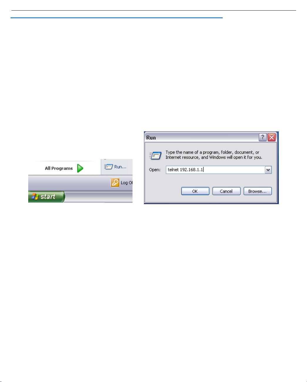
If you connect a PC with Microsoft Windows, you can use a Windows Telnet application or run Telnet from
the Start menu.
•
If you connect a Macintosh computer, Mac OS X users can use the Terminal application that comes with
Mac OS X in the Utilities folder.
Page 15
Introduction 1-5
Navigating through the Telnet Screens
Use your keyboard to navigate the Motorola Netopia® Embedded Software Version 8.7.4’s configuration
screens, enter and edit information, and make choices. The following table lists the keys to use to navigate
through the Telnet screens.
To... Use These Keys...
Move through selectable items in a screen or pop-up menu Up, Down, Left, and Right Arrow
Set a change to a selected item or open a pop-up menu of
options for a selected item like entering an upgrade key
Change a toggle value (Yes/No, On/Off) Tab
Restore an entry or toggle value to its previous value Esc
Move one item up Up arrow or Control + O
Move one item down Down arrow or Control + K
Page up Control + A
Page down Control + Z
Display a dump of the device event log Control + E
Display a dump of the WAN event log Control + F
Refresh the screen Control + L
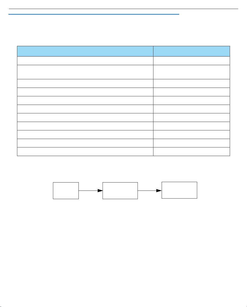
To help you find your way to particular screens, some sections in this guide begin with a graphical path guide
similar to the following example:
Main
Menu
System
Configuration
Return or Enter
IP Setup
This particular path guide shows how to get to the Network Protocols Setup screens. The path guide represents
these steps:
1. Beginning in the Main Menu, select System Configuration and press Return. The System Configuration
screen appears.
2. Select IP Setup and press Return. The IP Setup screen appears.
To go back in this sequence of screens, use the Escape key.
Page 16

1-6 Administrator’s Handbook
Page 17

WAN Configuration 2-1
Chapter 2
WAN Configuration
This chapter describes how to use the Telnet-based management screens to access and configure advanced
features of your equipment. You can customize these features for your individual setup. These menus provide a
powerful method for experienced users to set up their Router’s connection profiles configuration.
This section covers the following topics:
• “WAN Configuration” on page 2-1
• “WAN Ethernet Configuration screen” on page 2-1
• “ADSL Line Configuration screen” on page 2-4
• “Creating a New Connection Profile” on page 2-8
• “Advanced Connection Options” on page 2-15
• “Configuration Changes Reset WAN Connection” on page 2-15
• “Scheduled Connections” on page 2-16
• “Backup Configuration” on page 2-21
• “Diffserv Options” on page 2-22
• “Priority Queuing (TOS bit)” on page 2-25
• “VRRP Options (WAN Link Failure Detection)” on page 2-26
WAN Configuration
To configure your Wide Area Network (WAN) connection, navigate to the WAN Configuration screen from the Main
Menu and select WAN (Wide Area Network) Setup.
Main
Menu
The Line Configuration screen appears. The Line Configuration screen will be appropriate to the type of WAN
interface supported by your particular Router model.
WAN Ethernet Configuration screen
The WAN Ethernet Configuration screen appears as follows:
WAN
Configuration
WAN
Setup
Page 18

2-2 Administrator’s Handbook
WAN Ethernet Configuration
Address Translation Enabled: Yes
Obtain WAN address via DHCP: On
NAT Map List... Easy-PAT List
NAT Server List... Easy-Servers
NAT Options...
Stateful Inspection Enabled: No
Filter Set...
Remove Filter Set
WAN Ethernet Speed Setting... Auto-Negotiation
Wan Ethernet MAC Address: 00:0f:cc:0b:9d:ce
DHCP Client Mode: Standards-Based
RIP Options...
Set up the basic IP attributes of your Ethernet Module in this screen.
• Address Translation Enabled allows you to specify whether or not the router performs Network Address
Translation (NAT) on the Ethernet WAN port. NAT is enabled by default.
• Obtain WAN address via DHCP allows you to toggle WAN DHCP Off and On. DHCP is On by default. so that
if you do not change the setting, the Router will acquire its WAN IP address automatically. By default, the
router acts as a DHCP client on the Ethernet WAN port and and attempts to acquire an address from a
DHCP server.
• The Local WAN IP Address field allows you to manually configure an IP address for use on the Ethernet
WAN port. This field only becomes visible if you toggle Obtain WAN address via DHCP to Off.
• The Local WAN IP Mask field becomes visible if you specify a Local WAN IP Address. This allows you to
manually configure an IP subnet mask for use on the Ethernet WAN port. This item is visible only if you
have configured a non-zero Ethernet IP Address; other wise, the router obtains a subnet mask via DHCP.
• The NAT Map List and NAT Server List options are set to the defaults, Easy-PAT List and Easy-Servers.
These provide standard NAT mappings. For more advanced NAT configurations, see “Multi-NAT” on
page 4-1.
• NAT Options allows you to specify IP Passthrough, allowing a single PC on the LAN to have the router’s
public address assigned to it. See “IP Passthrough” on page 4-27.
• If you set Stateful Inspection Enabled to Yes , you can enable a security feature for computers on your LAN
when NAT is disabled. See “Stateful Inspection” on page 3-3.
• The Filter Set pop-up allows you to associate an IP filter set with the Ethernet WAN port. See “About Filters
and Filter Sets” on page 10-20.
• Remove Filter Set allows you to remove a previously associated filter set.
• The WAN Ethernet Speed Setting is configurable via a pop-up menu. Options are:
• Auto-Negotiation (the default)
Page 19

WAN Configuration 2-3
• 100 Mbps Full Duplex
• 100 Mbps Half Duplex
• 10 Mbps Full Duplex
• 10 Mbps Half Duplex
• 100 Mbps, Full Duplex, Fixed
• 100 Mbps, Half Duplex, Fixed
• 10 Mbps, Full Duplex, Fixed
• 10 Mbps, Half Duplex, Fixed
This may be useful in mixed networks, where multiple routers have different ethernet speed capability. If
you want to maintain a single speed setting for compatibility with multiple routers on your LAN, you can
select a speed/duplex combination that all of your routers can match.
• The Wan Ethernet MAC Address is the hardware address of the Motorola Netopia
providers require a specific MAC address as par t of their authentication process. In such a case, you can
enter the MAC address that your service provider requires. If your ser vice provider doesn’t use this
method, you don’t need to change this field.
®
device. Some service
• The DHCP Client Mode setting depends on the type of access concentrator equipment your service
provider uses. Most use Standards-Based. Alternatively, your provider may instruct you to select Copper
Mountain Specific.
• The RIP Options selection displays the WAN Ethernet RIP Parameters screen.
WAN Ethernet RIP Parameters
+----------------+
+----------------+
Receive RIP: | Off |
| v1 |
| v2 |
| Both v1 and v2 |
| v2 MD5 Authentication
+----------------+
• The Receive RIP pop-up menu controls the reception and transmission of Routing Information Protocol
(RIP) packets on the Ethernet WAN port. The default is Both.
Page 20

2-4 Administrator’s Handbook
The Transmit RIP pop-up menu is hidden if NAT is enabled.
Routing Information Protocol (RIP) is needed if there are IP routers on other segments of your Ethernet
network that the Motorola Netopia
®
Router needs to recognize. Set to “Both” (the default) Motorola
Netopia® Embedded Software Version 8.7.4 will accept information from either RIP v1 or v2 routers.
Alternatively, select Receive RIP and select v1, v2, or v2 MD5 Authentication from the popup menu. With
Receive RIP set to “v1,” the Motorola Netopia® Router’s Ethernet por t will accept routing information
provided by RIP packets from other routers that use the same subnet mask. Set to “v2,” the Motorola
Netopia® Embedded Software Version 8.7.4 will accept routing information provided by RIP packets from
other routers that use different subnet masks.
For more information on v2 MD5 Authentication, see “
RIP Options” on page 7-9.
If you want the Motorola Netopia® Router to advertise its routing table to other routers via RIP, select
Transmit RIP and select v1, v2 (broadcast), or v2 (multicast) from the popup menu. With Transmit RIP v1
selected, the Motorola Netopia® Embedded Software Version 8.7.4 will generate RIP packets only to other
RIP v1 routers. With Transmit RIP v2 (broadcast) selected, the Motorola Netopia® Embedded Software
Version 8.7.4 will generate RIP packets to all other hosts on the network. With Transmit RIP v2 (multicast)
selected, the Motorola Netopia® Embedded Software Version 8.7.4 will generate RIP packets only to other
routers capable of recognizing RIP v2 packets.
ADSL Line Configuration screen
The ADSL Line Configuration screen is shown below:
ADSL Line Configuration
Circuit Type... Multimode
Trellis Coding Enabled: On
Signaling Mode... FDM
Fast Retrain Enabled: On
Wiring Type... AutoSense
Data Link Encapsulation... RFC1483
Annex Modes enabled: Off
1. Select Circuit Type and from the pop-up menu choose the type of circuit to which you will be connecting:
Multimode, T1.413, G.dmt, or G.lite.
2. Select Trellis Coding Enabled. Toggle it to On (the default) or Off.
3. Select Signaling Mode and choose Echo Cancellation or FDM (the default).
4. If you selected Multimode Circuit Type, the Fast Retrain Enabled field appears. Toggle it to On (the default)
or Off.
Page 21

WAN Configuration 2-5
5. For model 3341 and 3366C ADSL modems, a Wiring Type pop-up menu allows you to choose the type of
copper pair wiring in use at your location. For all other models this option is preset and does not appear.
Usually, the default AutoSense will detect the type and adjust itself accordingly. If you want to set it
yourself, and you know the type of wiring you have, choose either Tip/Ring (Inner Pair) or A/A1 (Outer Pair)
from the pop-up menu.
6. Select Data Link Encapsulation and press Return. The pop-up menu will offer you the choice of PPP or
RFC1483.
7. Toggle Annex Modes enabled to On only if your service provider supports it. The embedded software has
the ability to support Annex M mode. However, Annex M mode may affect the training timing in some
cases. Consequently, the default is Off. Not all ser vices suppor t this feature for all subscribers.
ATM Circuit Configuration
On ADSL WAN interfaces, the Asynchronous Transfer Mode (ATM) connection between the router and the
central office equipment (DSLAM) is divided logically into one or more virtual circuits (VCs). A vir tual circuit may
be either a permanent vir tual circuit (PVC) or a switched vir tual circuit (SVC). Motorola Netopia® Routers
support PVCs.
VCs are identified by a Virtual Path Identifier (VPI) and Virtual Channel Identifier (VCI). A VPI is an 8-bit value
between 0 and 255, inclusive, while a VCI is a 16-bit value between 0 and 65535, inclusive.
• Circuits support attributes in addition to their VPI and VCI values. When configuring a circuit, you can
specify an optional circuit name of up to 14 characters. The circuit name is used only to identify the circuit
for management purposes as a convenience to aid in selecting circuits from lists. The default circuit name
is “Circuit <n>”, where <n> is some number between one and eight corresponding to the circuit’s position
in the list of up to eight circuits.
• You can also individually enable or disable a circuit without deleting it. This is useful for temporarily
removing a circuit without losing the configured attributes.
• In order to function, each circuit must be bound to a Connection Profile or to the Default Profile. Among
other attributes, the profile binding specifies the IP addressing information for use on the circuit. Each
circuit must be bound to a distinct Connection Profile.
ATM VPI/VCI Autodetection. You can bind multiple circuits to the same Connection Profile. Motorola Netopia®
Embedded Software Version 8.7.4 allows you to have a standard configuration that uses, for example, four VCs
(0/35, 0/38, 8/35, 8/38) pointing to the same profile.
The unit will now automatically select the active VC on networks with a VPI/VCI of any of these four values
without any custom configuration of the unit. You must, however, manually create these VCs and associate
them with the profile you desire.
You configure Virtual Circuits in the Add/Change Circuit screen.
Main
Menu
WAN
Configuration
ATM Circuits
Configuration
Page 22

2-6 Administrator’s Handbook
ATM Circuits Configuration
Show/Change Circuit...
Add Circuit...
Delete Circuit...
8. To add a circuit, select Add Circuit and press Return. The Add Circuit screen appears.
Add Circuit
Circuit Name: Circuit 2
Circuit Enabled: Yes
Circuit VPI (0-255): 0
Circuit VCI (32-65535): +-------------+
+-------------+
QoS... | UBR |
Peak Cell Rate (0 = line rate): | CBR |
| VBR |
+-------------+
Use Connection Profile... Default Profile
Use Default Profile for Circuit
ADD Circuit NOW CANCEL
• Enter a name for the circuit in the Circuit Name field.
• Toggle Circuit Enabled to Yes.
• Enter the Virtual Path Identifier and the Virtual Channel Identifier in the Circuit VPI and Circuit VCI
fields, respectively.
• The Peak Cell Rate field is editable. Motorola Netopia® Embedded Software Version 8.7.4 supports
three ATM classes of service for data connections: Unspecified Bit Rate (UBR), Constant Bit Rate
(CBR), and Variable Bit Rate (VBR). You can configure these classes of service on a per VC basis. The
Page 23

default ATM class of service is UBR.
Quality of Service (QoS) settings
Note: QoS settings are not available on Ethernet-to-Ethernet WAN models.
• Select the QoS (Quality of Service) setting from the pop-up menu: UBR. CBR, or VBR.
UBR: No configuration is needed for UBR VCs. Leave the default value 0 (maximum line rate).
CBR: One parameter is required for CBR VCs. Enter the Peak Cell Rate that applies to the VC. This
value should be between 1 and the line rate. You set this value according to specifications defined by
your service provider.
Add Circuit
Circuit Name: Circuit 2
Circuit Enabled: Yes
Circuit VPI (0-255): 0
Circuit VCI (32-65535): 32
QoS... VBR
Peak Cell Rate (0 = line rate): 0
Sustained Cell Rate: 0
Maximum Burst Size: 0
Use Connection Profile... Default Profile
Use Default Profile for Circuit
ADD Circuit NOW CANCEL
Return accepts * ESC cancels * Left/Right moves insertion point * Del deletes.
WAN Configuration 2-7
VBR: This class is characterized by:
• a Peak Cell Rate (PCR), which is a temporary burst, not a sustained rate, and
• a Sustained Cell Rate (SCR),
• a Burst Tolerance (BT), specified in terms of Maximum Burst Size (MBS). The MBS is the maximum
number of cells that can be transmitted at the peak cell rate and should be less than, or equal to the
Peak Cell Rate, which should be less than, or equal to the line rate.
VBR has two sub-classes:
a. VBR non-real-time (VBR-nrt): Typical applications are non-real-time traf fic, such as IP data traffic.
This class yields a fair amount of Cell Delay Variation (CDV).
b. VBR real time (VBR-rt): Typical applications are real-time traf fic, such as compressed voice over IP
and video conferencing. This class transmits cells with a more tightly bounded Cell Delay Variation.
The applications follow CBR.
• Then, select a Connection Profile for the Circuit. To use the Default Profile, select Use Default Profile
for Circuit and press Return. For other options, select a profile from the Use Connection Profile
pop-up menu.
Page 24

2-8 Administrator’s Handbook
Note: With multiple VCs you must explicitly statically bind the second (and all subsequent) VCs to a profile.
The first VC will automatically statically bind according to pre-defined dynamic binding rules when you add the
second VC. It will revert back to dynamic binding if the number of VCs is reduced to one; for example, by
deleting previously defined VCs.
When the link comes up the router binds the VC dynamically to the first suitable Connection Profile or to the
Default Profile if there is no Connection Profile configured.
• If you factory default the router, the VC binds to the Default Profile.
• If you delete a Connection Profile that is statically bound to a VC, the VC binding is set back to the Default
Profile. If there is only one VC defined, the VC dynamically binds to the first suitable profile or to the Default
Profile. If there are multiple VCs defined, it binds to the Default Profile.
• If you add a second VC, it is initialized to the Default Profile, and the menu screens display the VC
Connection Profile-related items, allowing you to bind to a specific Connection Profile instead of the Default
Profile. In addition, the router statically binds the first VC according to the rules used to select a profile for
dynamic binding. At this point, each profile uses static binding when the link is brought up.
• If there are no VCs when you add a VC -- for example, if you deleted all your previous VCs and star ted adding
them again -- dynamic binding will occur when the link comes up. If you delete a VC, leaving only one VC, that VC
resumes dynamically binding again.
• Select ADD Circuit NOW and press Return.
9. To display or change a circuit, select Display/Change Circuit, select a circuit from the pop-up menu, and
press Return. The fields are the same as those in the Add Circuit screen.
10. To delete a circuit, select Delete Circuit, select a circuit from the pop-up menu, and press Return. In the
confirmation window, select CONTINUE and press Return.
11. Press Escape to return to the WAN Setup menu.
Creating a New Connection Profile
Connection profiles are useful for configuring the connection and authentication settings for negotiating a PPP
connection. If you are using the PPP data link encapsulation method, you can store your authentication
information in the connection profile so that your user name and password (or host name and secret) are
transmitted when you attempt to connect.
Connection profiles define the networking protocols necessar y for the Router to make a remote connection. A
connection profile is like an address book entr y describing how the Router is to get to a remote site, or how to
recognize and authenticate a connection. To create a new connection profile, you navigate to the WAN
Configuration screen from the Main Menu, and select Add Connection Profile.
Page 25

WAN Configuration 2-9
Main
Menu
The Add Connection Profile screen appears.
Add Connection Profile
Profile Name: Profile 1
Profile Enabled: Yes
Encapsulation Type... RFC1483
RFC1483 Mode... Bridged 1483
IP Profile Parameters...
COMMIT CANCEL
Return accepts * ESC cancels * Left/Right moves insertion point * Del deletes.
Configure a new Conn. Profile. Finished? COMMIT or CANCEL to exit.
WAN
Configuration
Add Connection
Profile
1. Select Profile Name and enter a name for this connection profile. It can be any name you wish. For
example: the name of your ISP.
2. Toggle Profile Enabled to Ye s or No. The default is Yes. You can toggle it to No, if you want to disable it
later.
3. Select Encapsulation Type and press Return. The pop-up menu offers the possible data link encapsulation
methods for connection profiles used for a variety of purposes: PPP, RFC1483, ATMP, PPTP, IPsec, L2TP.
Multiple Data Link Encapsulation Settings
4. Select Encapsulation Options and press Return.
• If you selected ATMP, PPTP, L2TP, or IPSec, see Chapter 5, “Vir tual Private Networks (VPNs).”
Page 26

2-10 Administrator’s Handbook
• If you selected PPP or RFC1483, the screen offers different options:
Add Connection Profile
Profile Name: Profile 1
Profile Enabled: Yes
Encapsulation Type... +--------------+
+--------------+
RFC1483 Mode... | Bridged 1483 |
| Routed 1483 |
+--------------+
IP Profile Parameters...
COMMIT CANCEL
• If you selected RFC1483, the screen allows you
to choose Bridged 1483 or Routed 1483.
Add Connection Profile
Profile Name: Profile 1
Profile Enabled: Yes
Encapsulation Type... PPP
Underlying Encapsulation... None
PPP Mode... VC Multiplexed
Encapsulation Options...
IP Profile Parameters...
Interface Group... Primary
COMMIT CANCEL
Configure a new Conn. Profile. Finished? COMMIT or CANCEL to exit.
• If you selected PPP, the screen allows you to
choose PPPoE or None as the Underlying
Encapsulation.
• If you choose None, the PPP Mode offers the
choice of VC Multiplexed or LLC SNAP.
If you are using PPP, when you select Encapsulation Options, the Datalink (PPP/MP) Options screen
appears. (RFC1483 does not require these options and does not offer the menu selection.)
Page 27

WAN Configuration 2-11
Datalink (PPP/MP) Options
Data Compression... Standard LZS
Send Authentication... PAP
Send User Name:
Send Password:
Receive User Name:
Receive Password:
• Data Compression defaults to Standard LZS. You
can select Ascend LZS, if you are connecting to
compatible equipment, or None from the pop-up
menu.
• The Send Authentication pop-up menu lets you
select PAP, CHAP, or None.
• Selecting PAP or CHAP allows you to enter your
authentication credentials for both sending and
receiving connections.
PAP requires a User Name and Password;
CHAP requires a Host Name and Secret.
The screen changes to accommodate your
selection.
Datalink (PPP/MP) Options
Data Compression... Standard LZS
Send Authentication... PAP
Send User Name:
Send Password:
Receive User Name:
Receive Password:
Dial on Demand: Yes
Idle Timeout (seconds): 300
• If you are creating a Backup profile, you can
toggle Dial on Demand to Yes (the default) or No
and adjust the idle timeout in seconds from the
default 300 (5 minutes).
See “Line Backup” on page 8-1 for more
information.
Return to the Add Connection Profile screen by pressing Escape.
5. Select IP Profile Parameters and press Return. The IP Profile Parameters screen appears.
Page 28

2-12 Administrator’s Handbook
IP Profile Parameters
Address Translation Enabled: Yes
IP Addressing... Numbered
NAT Map List... Easy-PAT List
NAT Server List... Easy-Servers
NAT Options...
Stateful Inspection Enabled: No
Local WAN IP Address: 0.0.0.0
Local WAN IP Mask: 0.0.0.0
Filter Set...
Remove Filter Set
RIP Profile Options...
Return/Enter to select <among/between> ...
Configure IP requirements for a remote network connection here.
6. Toggle or enter your IP Parameters.
For more information, see:
• “IP Setup” on page 7-1
• “Network Address Translation (NAT)” on page 3-2
• “Stateful Inspection Options” on page 3-8
• “Filter Sets” on page 3-2
• The RIP Profile Options selection displays the RIP Profile Parameters screen.
Page 29

WAN Configuration 2-13
RIP Profile Parameters
+-----------------------+
+-----------------------+
Receive RIP: | Off |
| v1 |
| v2 |
| Both v1 and v2 |
| v2 MD5 Authentication |
+-----------------------+
• The Receive RIP pop-up menu controls the reception and transmission of Routing Information Protocol
(RIP) packets on the WAN port. The default is Both v1 and v2.
A Transmit RIP pop-up menu is hidden if NAT is enabled.
Routing Information Protocol (RIP) is needed if there are IP routers on other segments of your Ethernet
network that the Motorola Netopia® Router needs to recognize. Set to “Both” (the default) Motorola
Netopia® Embedded Software Version 8.7.4 will accept information from either RIP v1 or v2 routers.
Alternatively, select Receive RIP and select v1, v2, or v2 MD5 Authentication from the popup menu. With
Receive RIP set to “v1,” the Motorola Netopia® Router’s Ethernet por t will accept routing information
provided by RIP packets from other routers that use the same subnet mask. Set to “v2,” the Motorola
Netopia® Embedded Software Version 8.7.4 will accept routing information provided by RIP packets from
other routers that use different subnet masks.
For more information on v2 MD5 Authentication, see “
RIP Options” on page 7-9.
PPPoE/PPPoA Autodetection
Beginning with Software Version 8.5, if you are using PPP, and you have selected PPPoE as the Underlying
Encapsulation, you can further enable the ability to connect automatically to your ISP’s central office equipment
whether they are using PPP over Ethernet or PPP over ATM.
Note: This feature applies only to ATM-based WAN connections.
7. Select PPPoE Options and press Return.
The PPPoE Options screen appears.
Page 30

2-14 Administrator’s Handbook
PPPoE Options
PPPoA Autodetect: No
Return/Enter accepts * Tab toggles * ESC cancels.
Toggle PPPoA Autodetect to On.
If your ISP is using PPPoE, the connection will be made normally. If your ISP is using PPPoA, when the
Motorola Netopia® Gateway detects this, it will automatically switch to PPPoA transparently.
8. Return to the Add Connection Profile screen by pressing Escape.
9. Select COMMIT and press Return. Your new Connection Profile will be added.
If you want to view the Connection Profiles in your device, return to the WAN Configuration screen, and
select Display/Change Connection Profile. The list of Connection Profiles is displayed in a scrolling pop-up
screen.
WAN Configuration
+-Profile Name---------------------IP Address------+
+--------------------------------------------------+
| Easy Setup Profile 255.225.255.255 |
| Profile 1 0.0.0.0 |
| |
| |
| |
| |
| |
| |
| |
| |
| |
| |
| |
| |
| |
| |
+--------------------------------------------------+
Page 31

WAN Configuration 2-15
You can also delete Connection Profiles by selecting them in the same manner using the Delete Connection
Profile option in the WAN Configuration screen.
Advanced Connection Options
Depending on your model, the Advanced Connection Options screen offers a variety of powerful options for
advanced users. Screens shown in this section may vary from what your par ticular model displays.
Configuration Changes Reset WAN Connection
The menu supports delaying some configuration changes until after the Motorola Netopia® Router is restarted.
If your Motorola Netopia® Router is preconfigured by your ser vice provider, or if you are not remotely configuring
the router, you can leave this setting unchanged.
The purpose of this feature is to defer configuration changes only when remotely configuring or reconfiguring the
Motorola Netopia® Router to prevent premature Telnet disconnection. When this feature is enabled, no changes
to the WAN setup, datalink encapsulation, Connection Profiles, or Default Gateway will take effect until after the
Motorola Netopia® Router is restarted. Until the Motorola Netopia® Router is restarted the WAN link and the
routing table remain unaffected.
A single setting in the Advanced Connection Options screen controls this feature, as shown below.
Advanced Connection Options
Configuration Changes Reset WAN Connection: Yes
Scheduled Connections...
Backup Configuration...
Prioritize Delay-Sensitive Data: No
Diffserv Options...
VRRP Options...
Return/Enter to configure SA Backup Parameters.
When you toggle Configuration Changes Reset WAN Connection either to Yes or No using the Tab key and
press Return, a pop-up window asks you to confirm your choice.
Page 32

2-16 Administrator’s Handbook
Advanced Connection Options
+----------------------------------------------------+ No
+----------------------------------------------------+
| The Router will now be restarted to allow this |
| feature to function properly. |
| Are you sure you want to do this? |
| |
| CANCEL CONTINUE |
| |
+----------------------------------------------------+
Toggling from Ye s to No makes the router ready to be configured. If you toggle from No to Yes after any
configuration changes have been entered (and confirm the reboot), your changes are committed and the router
comes up using the newly created configuration.
Scheduled Connections
Scheduled connections are useful for PPPoE, PPTP, and ATMP connection profiles.
To go to the Scheduled Connections screen, from the WAN Configuration screen select Advanced Connection
Options and then select Scheduled Connections.
Main
Menu
WAN
Configuration
Advanced
Connection Options
Scheduled
Connections
Page 33

WAN Configuration 2-17
Scheduled Connections
Display/Change Scheduled Connection...
Add Scheduled Connection...
Delete Scheduled Connection...
Navigate from here to add/modify/change/delete Scheduled Connections.
Viewing scheduled connections
To display a table of scheduled connections, select Display/Change Scheduled Connection in the Scheduled
Connections screen. Each scheduled connection occupies one row of the table.
Scheduled Connections
+-Days----Begin At---HH:MM---When----Conn. Prof. Name----Enabled-----+
+--------------------------------------------------------------------+
| mtWtfss 08:30PM 06:00 weekly Profile 01 No |
| |
| |
| |
| |
| |
+--------------------------------------------------------------------+
The first column in the table shows a one-letter representation of the Days of the week, from Monday (M or m)
to Sunday (S or s). If a letter representing a day is capitalized, the connection will be activated on that day; a
lower-case letter means that the connection will not be activated on that day. If the scheduled connection is
configured for a once-only connection, the word “once” will appear instead of the days of the week.
The other columns show:
Page 34

2-18 Administrator’s Handbook
• The time of day that the connection will Begin At
• The duration of the connection (HH:MM)
• Whether it’s a recurring Weekly connection or used Once Only
• Which connection profile (Conn. Prof.) is used to connect
• Whether the scheduled connection is currently Enabled
The Router checks the date and time set in scheduled connections against the system date and time.
Adding a scheduled connection
To add a new scheduled connection, select Add Scheduled Connection in the Scheduled Connections screen
and press Return. The Add Scheduled Connection screen appears.
Add Scheduled Connection
Scheduled Connection Enable: On
How Often... Weekly
Schedule Type... Forced Up
Set Weekly Schedule...
Use Connection Profile...
ADD SCHEDULED CONNECTION CANCEL
Scheduled Connections dial remote Networks on a Weekly or Once-Only basis.
Follow these steps to configure the new scheduled connection:
• To activate the connection, select Scheduled Connection Enable and toggle it to On. You can make the
scheduled connection inactive by toggling Scheduled Connection Enable to Off.
• Decide how often the connection should take place by selecting How Often and choosing Weekly or Once
Only from the pop-up menu.
• The Schedule Type allows you to set the exact weekly schedule or once-only schedule.
Options are:
• Forced Up, meaning that this connection will be maintained whether or not there is a demand call on
the line.
• Forced Down, meaning that this connection will be torn down or blocked whether or not there is a
demand call on the line.
Page 35

WAN Configuration 2-19
• Demand-Allowed, meaning that this schedule will permit a demand call on the line.
• Demand-Blocked, meaning that this schedule will prevent a demand call on the line.
• Periodic, meaning that the connection is retried several times during the scheduled time.
• Random Retry, which operates as follows:
First, it will wait 0 to 60 seconds before starting, then it will tr y three times to bring the connection up as
quickly as possible;
Second, on each successive retry after these first three attempts it will wait a random number of seconds
between zero and a user-specified maximum.
Should the connection come up, and subsequently go down, the Scheduled Connection will start over with
three retries. Switched connections have a variable redial back-of f time depending on the inter face type.
Consequently, the first three attempts for such connections will be slower. Once the connection is up it will
be forced to remain up.
• If How Often is set to Weekly, the item directly below How Often reads Set Weekly Schedule. If How Often
is set to Once Only, the item directly below How Often reads Set Once-Only Schedule.
Set Weekly Schedule
If you set How Often to Weekly, select Set Weekly Schedule and go to the Set Weekly Schedule screen.
• Select the days for the scheduled connection to occur and toggle them to Yes .
Set Weekly Schedule
Monday: No
Tuesday: No
Wednesday: No
Thursday: No
Friday: No
Saturday: No
Sunday: No
Scheduled Window Start Time: 04:29
AM or PM: AM
Scheduled Window Duration Per Day: 00:00
Retry interval (minutes): 5
Return/Enter accepts * Tab toggles * ESC cancels.
• Select Scheduled Window Start Time and enter the time to initiate the scheduled connection.
• You must enter the time in the format H:M, where H is a one- or two-digit number representing the hour and
M is a one- or two-digit number representing the minutes. The colon is mandator y. For example, the entry
Page 36

2-20 Administrator’s Handbook
1:3 (or 1:03) would be accepted as 3 minutes after one o’clock. The entry 7:0 (or 7:00) would be accepted
as seven o’clock, exactly. The entries 44, :5, and 2: would be rejected.
• Select AM or PM and choose AM or PM from the pop-up menu.
• Select Scheduled Window Duration Per Day and enter the maximum duration allowed for this scheduled
connection, per call.
• Retry interval (minutes) becomes visible if you have selected Random Retr y. This option allows you to set
the upper limit for the number of minutes to use for the retry time (the attempts after the first three
attempts). It accepts values of 1 – 255 minutes; the default setting is 5 minutes. With a setting of 5
minutes it will try every 0 – 300 seconds after the first three retries to bring up the connection.
You are finished configuring the weekly options. Return to the Add Scheduled Connection screen to
continue.
Set Once-Only Schedule
If you set How Often to Once Only, select Set Once-Only Schedule and go to the Set Once-Only Schedule
screen.
Set Once-Only Schedule
Place Call on (MM/DD/YY): 05/07/1998
Scheduled Window Start Time: 11:50
AM or PM: AM
Scheduled Window Duration: 00:00
• Select Place Call On (Date) and enter a date in the format MM/DD/YY or MM/DD/YYYY (month, day,
year).
Note: You must enter the date in the format specified. The slashes are mandator y. For example, the entry
5/7/98 would be accepted as May 7, 1998. The entry 5/7 would be rejected.
• Select Scheduled Window Start Time and enter the time to initiate the scheduled connection.
Page 37

WAN Configuration 2-21
Note: You must enter the time in the format H:M, where H is a one- or two-digit number representing the
hour and M is a one- or two-digit number representing the minutes. The colon is mandator y. For example,
the entry 1:3 (or 1:03) would be accepted as 3 minutes after one o’clock. The entry 7:0 (or 7:00) would be
accepted as seven o’clock, exactly. The entries 44, :5, and 2: would be rejected.
• Select AM or PM and choose AM or PM.
• Select Scheduled Window Duration and enter the maximum duration allowed for this scheduled
connection. Use the same format restrictions noted above.
You are finished configuring the once-only options. Return to the Add Scheduled Connection screen to continue.
• In the Add Scheduled Connection screen, select Use Connection Profile and choose from the list of
connection profiles you have already created. A scheduled connection must be associated with a
connection profile to be useful. The connection profile becomes active during the times specified in the
associated scheduled connection, if any exists.
• Select ADD SCHEDULED CONNECTION to save the current scheduled connection. Select CANCEL to exit
the Add Scheduled Connection screen without saving the new scheduled connection.
Modifying a scheduled connection
To modify a scheduled connection, select Display/Change Scheduled Connection in the Scheduled
Connections screen to display a table of scheduled connections.
Select a scheduled connection from the table and press Return. The Change Scheduled Connection screen
appears. The parameters in this screen are the same as the ones in the Add Scheduled Connection screen
(except that ADD SCHEDULED CONNECTION and CANCEL do not appear). To find out how to set them, see
“Adding a scheduled connection” on page 2-18.
Deleting a scheduled connection
To delete a scheduled connection, select Delete Scheduled Connection in the Scheduled Connections screen
to display a table of scheduled connections.
Select a scheduled connection from the table and press the Return key to delete it. To exit the table without
deleting the selected scheduled connection, press the Escape key.
Backup Configuration
See “Line Backup” on page 8-1.
Page 38

2-22 Administrator’s Handbook
Diffserv Options
Motorola Netopia® Embedded Software Version 8.7.4 offers Differentiated Ser vices (Dif fser v) enhancements.
These enhancements allow your Router to make Quality of Service (QoS) decisions about what path Internet
traffic, such as Voice over IP (VoIP), should travel across your network. For example, you may want streaming
video conferencing to use high quality, but more restrictive, connections, or, you might want e-mail to use less
restrictive, but less reliable, connections.
When you select Diffserv Options, the Diffser ve Options configuration screen appears.
Diffserv Options
Diffserv Enabled: No
• Differentiated Services is disabled by default. To enable Differentiated Ser vices, toggle Diffserv Enabled to
Yes and press Return.
The Diffserv options are displayed.
Page 39

WAN Configuration 2-23
Diffserv Options
Diffserv Enabled: Yes
Lo/Hi Ratio: 0
Show/Change Rules...
Add Rules...
Return accepts * ESC cancels * Left/Right moves insertion point * Del deletes.
• Enter a value from 60 to 100 (percent) in the Lo/Hi Ratio field.
Differentiated Services uses the low-to-high priority queue ratio to regulate traffic flow. For example, to
provide the least possible latency and highest possible throughput for high priority traffic, you could set the
ratio to 100(%). This would cause the Router to forward low priority data only after the high priority queue is
completely empty. In practice, you should set it to something less than 100%, since the low priority traffic
might have to wait too long to be passed, and consequently be subject to time-outs.
When the LoHi value is 50 or below, it is equivalent to turning off the ser vice.
Note: Low to High Priority Queue Asymmetry Field (lohi-asymmetry)
This parameter is a percentage between 50 and 100 used to regulate the level of packets allowed to be pending in the low
priority queue. It can be used to some degree to adjust the relative throughput bandwidth for low vs. high priority traf fic.
For example, to provide for least possible latency and highest throughput for high priority packets, you can set the
lohi-asymmetry to 100%. This will cause the gateway to forward low priority packets only when the high priority queue is
completely empty. If the high priority stream throughput is such that it fully loads the Gateway, the low priority stream will in
this case be completely suppressed. If it is a TCP stream, it probably will time out. To keep low priority TCP connections
“alive” with minimal throughput while other applications are loading the Gateway with high priority traffic, you might try
setting the parameter to 90%. The means a low priority packet will be forwarded whenever the relative packet count
asymmetry, defined as (low)/(high + low) with is greater than .90.
Lowering the lohi-asymmetry value will lower the throughput and widen the latency distribution of the high priority streams,
so for best results, especially during heavy high priority loading, the value should be left high. Setting the field to 50%, for
example, is almost equivalent to turning off the service as far as the Gateway's behavior is concerned.
Much of the benefit of DiffSer ve is a cumulative one obser ved as packets traverse the nodes on a network from endpoint to
endpoint. A small improvement in the latency distribution for the flow through a single network node (such as a Motorola
Netopia
packets in a stream can be minimized through 10 or 20 nodes in the route to the other end of the conversation, however,
the cumulative difference may be very noticeable.
In general, a VoIP call, for example, is low bandwidth – bi-directional UDP streams totaling about 20 packets/sec, or
®
“edge” Gateway) may not be especially noticeable in a VoIP conversation, for example. If the latency for the VoIP
Page 40

2-24 Administrator’s Handbook
bandwidths from 20 kbps to 90 kbps, depending on the CODEC setting – compared to the total throughput bandwidth of the
Gateway and the network. There will usually be fewer than two or three packets pending in the Gateway in any queue in the
Gateway during the conversation. If, during the call, however, a user is surfing and decides to download, or upload, a file
through the Gateway, it is possible that during the file transfer the voice quality of the VoIP call could be degraded. A higher
setting for the lohi-asymmetry will prevent this from occurring.
On the other hand, if 10 or 20 VoIP calls are simultaneously being handled by the Gateway, for example, in an of fice setting,
then 1000-2000 packets/sec are being throughput at high priority. If one or several of the callers in the office then attempt
to download, 10-15 packets may be pending in the low priority receive queues, with perhaps 2-3 pending in the high. The
corresponding asymmetr y in this case would be around 80-86%. If it were found in this situation that the file transfers were
too sluggish, then the lohi-asymmetry threshold could be set to 80%. This would cause more of the low priority traffic to be
throughput, at the expense of the high priority streams. As a result, the file downloads might proceed at a more satisfactor y
rate, while the degradation to the 10 or 20 VoIP calls might not be noticeable.
The lo-hi asymmetry parameter is therefore one means of balancing the traffic load to satisfy everyone.
You can then define custom Rules. If your applications do not provide Quality of Service (QoS) control, rules
allow you to define streams for some protocols, por t ranges, and between specific end point addresses.
• To define a Rule, select Add Rules and press Return.
(Once you have added one or more rules, you can edit any of them by returning to this screen and selecting
Show/Change Rules.)
The Diffserv Rule screen appears.
Diffserv Rule
Name:
Protocol... TCP
Priority... off
Direction... outbound
Start Port: 0
End Port: 0
Inside Ip Address: 0.0.0.0
Inside Ip Netmask: 0.0.0.0
Outside Ip Address: 0.0.0.0
Outside Ip Netmask: 0.0.0.0
COMMIT CANCEL
Return accepts * ESC cancels * Left/Right moves insertion point * Del deletes.
• Name – Enter a name in this field to label the rule.
• Protocol – Select the protocol from the pop-up menu: TCP (default), UDP, ICMP, or Other. “Other” is
appropriate for setting up rules on protocols with non-standard port definitions. IPSEC and PPTP are
common examples.
Page 41

WAN Configuration 2-25
• Priority – This is the Quality of Service setting for the rule, based on the TOS bit information. Select
assure, expedite, or off (default) from the pop-up menu. The following table outlines the TOS bit settings
and behavior:
QoS Setting TOS Bit Value Behavior
off TOS=000 This custom rule is disabled. You can activate it by selecting one of
the two settings below. This setting allows you to pre-define flows
without actually activating them.
assure TOS=001 Use normal queuing and throughput rules, but do not drop packets
if possible. Appropriate for applications with no guaranteed delivery
mechanism.
expedite TOS=101 Use minimum delay. Appropriate for VoIP and video applications.
• Numerical Protocol – If you select “Other” protocol, this field appears for you to provide its actual protocol
number, with a range of 0 – 255.
• Direction – Choose outbound (default), inbound, or both from the pop-up menu.
• Start Por t – For TCP or UDP protocols, you can optionally specify a range of por ts. Enter the star ting por t
here.
• End Port – Enter the ending por t here.
• Inside IP Address/Netmask – For outbound flows, specify an IP address and subnet mask on your LAN. For
inbound flows, this setting is ignored.
• Outside IP Address/Netmask – If you want traffic destined for and originating from a certain WAN IP
address to be controlled, enter the IP address and subnet mask here. If you leave the default all-zeroes,
the outside address check is ignored.
For outbound flows, the outside address is the destination IP address for traffic; for inbound packets, the
outside address is the source IP address.
When you are finished, select COMMIT and press Return. You will be returned to the Diffser v Options screen
and your settings will take effect.
Priority Queuing (TOS bit)
Motorola Netopia® Embedded Software Version 8.7.4 offers the ability to prioritize delay-sensitive data over the
WAN link on DSL connections.
Certain types of IP packets, such as voice or multimedia packets, are sensitive to latency introduced by the
network. This means that if such packets are not received rapidly, the quality of service degrades. If you expect
to route significant amounts of such traffic you can configure your router to prioritize this type of traffic using the
priority queuing feature.
To configure your router to prioritize delay-sensitive data, navigate to the Advanced Connection Options screen
in the console menu.
Page 42

2-26 Administrator’s Handbook
Main
Menu
WAN
Configuration
Advanced Connection
Options
The Advanced Connection Options screen appears.
Advanced Connection Options
Configuration Changes Reset WAN Connection: Yes
Scheduled Connections...
Backup Configuration...
Prioritize Delay-Sensitive Data: No
Diffserv Options...
VRRP Options...
Return/Enter to configure SA Backup Parameters.
The Router will recognize a delay-sensitive packet as having the low-latency bit set in the TOS field of the IP
header.
If you toggle Prioritize Delay-Sensitive Data to Yes the router will place these packets at the front of the
transmission queue to the WAN link, overtaking non-delay-sensitive traf fic. Accepting the default No will allow
the normal sequential queue of data packets.
VRRP Options (WAN Link Failure Detection)
Beginning with Software Version 8.5.1, the software offers VRRP Options to detect Layer 3 link failures on the
WAN. When you enable this feature, the Motorola Netopia® Router will continuously Ping one or two hosts that
you specify to determine when a link fails, even if the physical connection remains established. If Layer 3 WAN
Link Failure Detection is enabled, the Motorola Netopia® Router will send continuous Pings, so the WAN link will
stay up and idle timeout will not occur.
See “Virtual Router Redundancy (VRRP)” on page 7-34 for a detailed description of VRRP and how to create
Virtual Routers.
To enable WAN Link Failure Detection, select VRRP Options in the Advanced Connection Options menu. The
VRRP Options menu appears.
Page 43

VRRP Options
WAN Link Failure Detection:
Ping Enable: Off
Return/Enter accepts * Tab toggles * ESC cancels.
Toggle Ping Enable to On and press Return. The Ping settings options appear.
VRRP Options
WAN Link Failure Detection:
Ping Enable: On
Ping Host Name or IP Address #1:
Ping Host Name or IP Address #2:
Delay (s): 5
Ping failures: 10
WAN Configuration 2-27
• The Ping Host Name or IP Address #1 and Ping Host Name or IP Address #2 fields allow you to enter the
fully-qualified host name(s) or IP address(es) in standard dotted-quad format of the hosts you want to Ping
for connection validation. If no ICMP echo(es) are returned from these hosts, the connection is assumed to
be lost, and the Virtual Router will relinquish Master status.
• The Delay (s) field allows you to specify the time in seconds between Pings. The default is five (5) seconds.
• The Ping failures field allows you to specify the number of Ping time-outs or failures after which the
connection is assumed to be lost. The default is ten (10).
Page 44

2-28 Administrator’s Handbook
Page 45

System Configuration 3-1
Chapter 3
System Configuration
This chapter describes how to use the Telnet-based management screens to access and configure advanced
features of your equipment. You can customize these features for your individual setup. These menus provide a
powerful method for experienced users to set up their Router’s system configuration.
System Configuration Features
The Motorola Netopia® Router’s default settings may be all you need to configure. Some users, however,
require advanced settings or prefer manual control over the default selections. For these users, Motorola
Netopia® Embedded Software Version 8.7.4 provides many advanced system configuration options.
This section covers the following topics:
• “IP Setup” on page 3-2 • “Wireless configuration” on page 3-38
• “Filter Sets” on page 3-2 • “Console Configuration” on page 3-49
• “IP Address Serving” on page 3-2 • “SNMP (Simple Network Management Protocol)”
on page 3-50
• “Network Address Translation (NAT)” on
page 3-2
• “Security” on page 3-50
• “Stateful Inspection” on page 3-3 • “Upgrade Feature Set” on page 3-50
• “Procedure for Default Installation for ICSA
firewall certification of Small/Medium
Business Category Module (ADSL Routers)”
on page 3-60
• “Router/Bridge Set” on page 3-51
• “VLAN Configuration” on page 3-11 • “IGMP (Internet Group Management Protocol)”
on page 3-52
• “Date and time” on page 3-37 • “Logging” on page 3-55
To access the system configuration screens, select System Configuration in the Main Menu and press Return.
The System Configuration menu screen appears:
Page 46

3-2 Administrator’s Handbook
System Configuration
IP Setup...
Filter Sets...
IP Address Serving...
Network Address Translation (NAT)...
Stateful Inspection...
VLAN Configuration...
Date and Time...
Wireless Configuration...
Console Configuration
SNMP (Simple Network Management Protocol)...
Security...
Upgrade Feature Set...
Router/Bridge Set... Router
IGMP (Internet Group Management Protocol)...
Logging...
Use this screen if you want options beyond Easy Setup.
IP Setup
These screens allow you to configure your network’s use of the IP networking protocol.
• Details are given in “IP Setup” on page 7-1.
Filter Sets
These screens allow you to configure security on your network by means of filter sets and a basic firewall.
• Details are given in “Security” on page 10-1.
IP Address Serving
These screens allow you to configure IP address ser ving on your network by means of DHCP, WANIP, and BootP.
• Details are given in “IP Address Serving” on page 7-17.
Network Address Translation (NAT)
These screens allow you to configure the Multiple Network Address Translation (MultiNAT) features.
• Details are given in “Multi-NAT” on page 4-1.
Page 47

System Configuration 3-3
Stateful Inspection
Stateful inspection is a security feature that prevents unsolicited inbound access when NAT is disabled.
Stateful inspection can be enabled on a Connection Profile whether NAT is enabled or not. You can configure
UDP and TCP “no-activity” periods that will also apply to NAT time-outs if stateful inspection is enabled on the
interface. Stateful Inspection parameters are active on a WAN interface only if enabled on your Gateway.
Stateful Inspection
UDP no-activity timeout (sec): 180
TCP no-activity timeout (sec): 14400
DoS Detect: No
Add Exposed Address List...
Exposed Address Associations...
Return/Enter goes to new screen.
Return/Enter to configure Xposed IP addresses.
• UDP no-activity time-out: The time in seconds after which a UDP session will be terminated, if there is no
traffic on the session.
• TCP no-activity time-out: The time in seconds after which an TCP session will be terminated, if there is no
traffic on the session.
• DoS Detect: If you toggle this option to Yes , the device will monitor packets for Denial of Ser vice (DoS)
attack. Offending packets may be discarded if it is determined to be a DoS attack.
• Add Exposed Address List: Accesses the Add Exposed Address List screen. See “Add Exposed Address
List” on page 3-3.
• Exposed Address Associations: Accesses the Exposed Address Associations screen. See “Exposed
Address Associations” on page 3-7. The hosts specified in Exposed addresses will be allowed to receive
inbound traffic even if there is no corresponding outbound traf fic. This is active only if NAT is disabled on a
WAN interface. An Exposed Address List can be associated with a Connection Profile only if NAT is disabled
and Stateful Inspection is enabled on the profile.
Add Exposed Address List
You can specify the IP addresses you want to expose by selecting Add Exposed Address List from the Stateful
Inspection menu and pressing Return.
Page 48

3-4 Administrator’s Handbook
Stateful Inspection
UDP no-activity timeout (sec): 180
TCP no-activity timeout (sec): 14400
Add Exposed Address List...
Exposed Address Associations...
Return/Enter goes to new screen.
Return/Enter to configure Xposed IP addresses.
The Add Exposed Address List screen appears.
Add Exposed Address List
Exposed Address List Name: xposed_list_1
Return accepts * ESC cancels * Left/Right moves insertion point * Del deletes.
Enter a descriptive name for the list and press Return. A new field Add Exposed Address Range appears.
Page 49

Add Exposed Address List
Exposed Address List Name: xposed_list_1
Add Exposed Address Range...
Return/Enter goes to new screen.
Select Add Exposed Address Range and press Return.
The Exposed Address Range screen appears.
System Configuration 3-5
Add Exposed Address Range ("xposed_list_1")
First Exposed Address: 0.0.0.0
Last Exposed Address: 0.0.0.0
Protocol... ANY
ADD EXPOSED ADDRESS RANGE CANCEL
Enter an IP address in decimal and dot form (xxx.xxx.xxx.xxx).
Enter the First and Last Exposed Addresses in dotted-quad format for the range of IP addresses you want to
expose,
The pop-up Protocol menu offers the type of protocols to be assigned to this range.
Page 50

3-6 Administrator’s Handbook
Add Exposed Address Range ("xposed_list_1")
First Exposed Address: 192.168.1.10
Last Exposed Address: +-------------+
+-------------+
Protocol... | TCP and UDP |
| TCP |
| UDP |
| ANY |
+-------------+
ADD EXPOSED ADDRESS RANGE CANCEL
Add Exposed Address Range ("xposed_list_1")
First Exposed Address: 192.168.1.10
Last Exposed Address: 192.168.1.12
Protocol... TCP and UDP
Port Start: 0
Port End: 0
ADD EXPOSED ADDRESS RANGE CANCEL
Return accepts * ESC cancels * Left/Right moves insertion point * Del deletes.
• First Exposed Address: Start IP Address of the exposed host range.
• Last Exposed Address: End IP Address of the exposed host range
• Protocol: Select the Protocol of the traffic to be allowed to the host range from the pop-up menu. Options
are Any, TCP, UDP, or TCP and UDP.
• Port Star t: Star t por t of the range to be allowed to the host range. The acceptable range is from 1 -
65535.
• Port End: End por t of the range to be allowed to the host range. The acceptable range is from 1 - 65535.
Page 51

System Configuration 3-7
You can edit or delete exposed address lists by selecting Show/Change Exposed Address List or Delete
Exposed Address List. A list of previously configured exposed addresses appears. This allows you to select an
exposed address list for editing or deletion.
Add Exposed Address List
+------Exposed Address Range---------Protocol-------------------+
+---------------------------------------------------------------+
| 192.168.1.10 192.168.1.12 TCP and UDP |
| |
| |
| |
| |
| |
| |
| |
| |
| |
| |
| |
| |
| |
| |
| |
+---------------------------------------------------------------+
Up/Down Arrow Keys to select, ESC to dismiss, Return/Enter to Edit.
Note: Add, Edit, or Delete exposed addresses options are active only if NAT is disabled on a WAN interface.
The hosts specified in exposed addresses will be allowed to receive inbound traffic even if there is no
corresponding outbound traf fic.
Exposed Address Associations
Enable and configure stateful inspection on a WAN interface.
Page 52

3-8 Administrator’s Handbook
IP Profile Parameters
Address Translation Enabled: Yes
IP Addressing... Numbered
NAT Map List... Easy-PAT List
NAT Server List... Easy-Servers
NAT Options...
Stateful Inspection Enabled: No
Local WAN IP Address: 0.0.0.0
Local WAN IP Mask: 0.0.0.0
Filter Set...
Remove Filter Set
RIP Profile Options...
Return/Enter to select <among/between> ...
Configure IP requirements for a remote network connection here.
When you create or modify a Connection Profile, the IP Profile Parameters screen allows you to enable Stateful
Inspection on that profile by toggling Stateful Inspection Enabled to Yes . By default, this is turned off (No). If
you enable Stateful Inspection, the Stateful Inspection Options field appears.
Stateful Inspection Options
IP Profile Parameters
Address Translation Enabled: No
IP Addressing... Numbered
Stateful Inspection Enabled: Yes
Stateful Inspection Options...
Local WAN IP Address: 0.0.0.0
Local WAN IP Mask: 0.0.0.0
Filter Set...
Remove Filter Set
RIP Profile Options...
Configure IP requirements for a remote network connection here.
Select Stateful Inspection Options and press Return. The Stateful Inspection Parameters screen appears.
Page 53

System Configuration 3-9
Stateful Inspection Parameters
Max. TCP Sequence Number Difference: 0
Enable default mapping to router: No
Deny Fragmented Packets: No
Exposed Address List...
Enter max. allowed TCP sequence number difference (1 - 65535), 0 to disable.
• Max. TCP Sequence Number Difference: Enter a value in this field. This value represents the maximum
sequence number difference allowed between subsequent TCP packets. If this number is exceeded, the
packet is dropped. The acceptable range is 0 – 65535. A value of 0 (zero) disables this check.
• Enable default mapping to router: This is disabled by default. Toggling this option to Yes will allow the
router to respond to traffic received on this inter face, for example, ICMP Echo requests.
Note: If Stateful Inspection is enabled on a base connection profile (for example, for PPP, RFC1483
bridged/routed, or PPPoE), Enable default mapping to router must be yes to allow inbound VPN terminations.
(for example. for PPTP/ATMP client access to the router)
• Deny Fragmented Packets: Toggling this option to Yes causes the router to discard fragmented packets on
this interface.
• You can apply these parameters to your Exposed Address lists by selecting your Exposed Address List
from the pop-up menu,
Page 54

3-10 Administrator’s Handbook
Stateful Inspection Parameters
+Exposed Address List N+
+----------------------+
Max. TCP Sequ| xposed_list_1 | 0
| <<None>> |
Enable defaul| | No
| |
Deny Fragment| | No
| |
Exposed Addre| |
| |
| |
| |
| |
| |
| |
| |
| |
| |
+----------------------+
Up/Down Arrows to select, then Return/Enter; ESC to cancel.
Open ports in default Stateful Inspection installation
Port Protocol Description Private Interface Public Interface
23 TCP telnet Yes No
53 UDP DNS Yes No
67 UDP Bootps Yes No
68 UDP Bootpc Yes No
80 TCP HTTP Yes No
137 UDP Netbios-ns Yes No
138 UDP Netbios-dgm Yes No
161 UDP SNMP Yes No
500 UDP ISAKMP Yes No
520 UDP Router Yes No
1701 UDP L2TP Yes No
1900 UDP UPnP Yes No
1723 TCP PPTP Yes No
Page 55

System Configuration 3-11
VLAN Configuration
Overview
A Virtual Local Area Network (VLAN) is a network of computers or other devices that behave as if they are
connected to the same wire even though they may be physically located on different segments of a LAN. You
set up VLANs by configuring the Gateway software rather than hardware. This makes VLANs ver y flexible. VLANs
behave like separate and independent networks.
Beginning with Version 8.7.4, VLANs are now strictly layer 2 entities. They can be thought of as virtual Ethernet
switches, into which can be added: Ethernet por ts, router IP inter faces, ATM PVC/VCC interfaces, SSIDs, and
any other physical port such as USB, HPNA, or MOCA. This allows great flexibility in how the components of a
system are connected to each other.
VLANs are part of Motorola’s VGx Vir tual Gateway technology which allows individual por t-based VLANs to be
treated as separate and distinct “channels.” When data is passed to a Motorola Netopia® VGx-enabled
broadband gateway, specific policies, routing, and prioritization parameters can be applied to each individual
service, delivering that service to the appropriate networked device with the required level of quality of ser vice
(QoS). In effect, a single Motorola gateway acts as separate virtual gateways for each distinct service being
delivered.
Motorola’s VGx technology provides ser vice segmentation and QoS controls, and suppor ts deliver y of triple play
applications: voice for IP Telephony, video for IPTV, and data.
Your Gateway suppor ts the following:
• Global VLANs - these are used when trunking/tagging is required on any port member of the VLAN. Trunks
are used to interconnect switches to form networks. The VLANs can communicate with each other via a
trunking connection between the two switches using the router.
- Supports 802.1q and 802.1p; both are configurable
• Port-based VLANs - these can be used when no trunking is required
• Routed VLANs
- WAN-side VLAN with Multiple WAN IPoE/PPPoE interface suppor t and IP inter face-to-VLAN binding
- LAN-side VLAN with IP interface-to-VLAN binding
- Inter-VLAN routing groups to extend VLAN segmentation up through the IP routing layer.
• Bridged VLANs - these VLANs are used to bridge traffic from LAN to WAN
• Prioritization per VLAN and per port
Page 56

3-12 Administrator’s Handbook
Ethernet Switching/Policy Setup
Before you configure any VLANs, an unconfigured Gateway is set up as a router composed of a LAN switch, a
WAN switch, and a router in the middle, with LAN and WAN IP interfaces connected to their respective switches.
These bindings between Ethernet switch por ts, IP LAN inter face, IP WAN interface and WAN physical ports are
automatically created.
When you configure any VLANs, the default bindings are no longer valid, and the system requires explicit binding
between IP interfaces and layer 2 interfaces. Each VLAN can be thought of as a layer 2 switch, and enabling
each port or interface in a VLAN is analogous to plugging it in to the layer 2 switch.
Thereafter, in order for devices to communicate on layer 2, they must be associated in the same VLAN. For
devices to communicate at layer 3, the devices must be either on the same VLAN, or on VLANs that have an
Inter-VLAN routing group enabled in common.
When configuring VLANs you must define how traffic needs to be forwarded:
• If traffic needs to be bridged between LAN and WAN you can create a single VLAN that encompasses the
WAN port and LAN por ts.
• If traffic needs to be routed then you must define four elements:
• LAN-side VLANs
• WAN-side VLANs
• Associate IP Interfaces to VLANs
• Inter-VLAN Routing Groups: configuration of routing between VLANs is done by association of a VLAN to a
Routing Group. Traffic will be routed between VLANs within a routing group. The LAN IP Ethernet Inter face
can be bound to multiple LAN VLANs, but forwarding can be limited between an Ethernet LAN por t and a
WAN VLAN if you properly configure Inter-VLAN groups.
Inter-VLAN groups are also used to block routing between WAN interfaces. If each WAN IP interface is
bound to its own VLAN and if you configure a different Inter-VLAN group for each WAN VLAN then no routing
between WAN IP interfaces is possible.
• Example: to route between a VCC and all the LAN ports, which effectively is similar to the default
configuration without any VLANs:
Create a VLAN named "WAN" consisting of your Connection Profile and Inter-VLAN-Routing Group-1
Create a VLAN named "LAN" consisting of Eth 0/1, Eth 0/2, Eth 0/3, Eth 0/4, SSID 1, SSID 2, SSID 3,
SSID 4 (etc.), and Inter-VLAN-Routing Group-1
Page 57

System Configuration 3-13
An example of multiple VLANs, using a Netopia Router with VGx managed switch technology, is shown below:
A VLAN Model Combining Bridging and Routing
Page 58

3-14 Administrator’s Handbook
To configure VLANs, select VLAN Configuration in the System Configuration screen and press Return.
The VLAN Configuration screen appears.
VLAN Configuration
VLAN Enable: Off
Set Up VLAN from this and the following Menus.
Toggle VLAN Enable to On and press Return.
The Add VLAN selection appears.
VLAN Configuration
VLAN Enable: On
Add VLAN...
Authentication Server Configuration...
Return/Enter to select <among/between> ...
Set Up VLAN from this and the following Menus.
Select Add VLAN and press Return.
Page 59

System Configuration 3-15
The Add VLAN screen appears.
Add VLAN...
VLAN ID (1-4094): 0
VLAN Type... port-based
VLAN Name:
VLAN Network: <None>
Inter-VLAN-Routing...
802.1x: No
Once a VLAN has been successfully added, configure ports using the
"Add Port Interface" option of the "Display/Change VLAN" menu.
ADD VLAN CANCEL
Return accepts * ESC cancels * Left/Right moves insertion point * Del deletes.
Configure a new VLAN and its associated ports.
You can create up to 16 VLANs, and you can also restrict any VLAN, and the computers on it, from
administering the Router.
• VLAN ID – The VLAN ID field allows you to enter a VID. This must be a unique identifying number between 1
and 4094. (A VID of zero (0) is permitted on the Ethernet WAN port only.)
• VLAN Type – LAN or WAN Port(s) can be enabled on the VLAN. See “Adding Port interfaces” on page 3-20
for more information. You can choose a type designation as follows:
port-based: Traffic sent to this port will be treated as belonging to the VLAN, and will not be for warded to
other ports that are not within a common VLAN segment.
global: Indicates that the ports joining this VLAN are part of a global 802.1q Ethernet VLAN. This VLAN
includes ports on this Router and may include ports within other devices throughout the network. The VID
in this case may define the behavior of traffic between all devices on the network having ports that are
members of this VLAN segment.
• VLAN Name – A descriptive name for the VLAN.
Page 60

3-16 Administrator’s Handbook
• VLAN Network – From the VLAN Network pop-up menu select None, Primary LAN, a Connection Profile (for
the IP networking configuration) or, if you have configured an Additional LAN (ALAN), an Additional LAN. See
“Additional LANs” on page 7-38.
Add VLAN...
+-Name---------------------------IP Address------+
+------------------------------------------------+
| Primary LAN 192.168.1.1 |
| Additional LAN 1 0.0.0.0 |
| Additional LAN 2 1.1.1.1 |
| Easy Setup Profile 127.0.0.2 |
| <None> |
| |
+------------------------------------------------+
Once a VLAN has been successfully added, configure ports using the
"Add Port Interface" option of the "Display/Change VLAN" menu.
ADD VLAN CANCEL
• 802.1x – This option is only available for Router models with VGx technology. Otherwise, it does not
appear. If you are configuring a VLAN for a Motorola Netopia® Router model with VGx technology (wired or
wireless), you can specify a RADIUS server for user authentication by toggling 802.1x to Ye s . See “Adding
a RADIUS Profile” on page 3-18. The default is No.
Page 61

System Configuration 3-17
Associating Inter-VLAN Routing Groups
Note: You must first ADD the VLAN before associating the Inter-VLAN-Routing Groups or the Port Interfaces.
Once you have added the VLAN, you access the Inter-VLAN-Routing screen and the Add Port Inter face screen by
selecting Display/Change VLAN from the VLAN Configuration screen.
• Inter-VLAN-Routing – Inter-VLAN groups allow VLANs in the group to route traf fic to the others as discussed
on page 3-12; ungrouped VLANs cannot route traffic to each other.
When you select Inter-VLAN-Routing, the Inter-VLAN-Routing screen appears.
Inter-VLAN-Routing
VLAN Group-1 Enabled: Off
VLAN Group-2 Enabled: Off
VLAN Group-3 Enabled: Off
VLAN Group-4 Enabled: Off
VLAN Group-5 Enabled: Off
VLAN Group-6 Enabled: Off
VLAN Group-7 Enabled: Off
VLAN Group-8 Enabled: Off
For each VLAN Group that you want to route traffic to each other, toggle VLAN Group-n Enabled to On and
press Return.
Press Escape to return to the Add VLAN screen.
Page 62

3-18 Administrator’s Handbook
Adding a RADIUS Profile
• Authentication Profile – If you toggle 802.1x to Yes, this option displays. Select Authentication Profile and
press Return.
If you have RADIUS server profiles already defined, the pop-up menu allows you to select one for use with
this VLAN. If none are defined, the pop-up menu offers the option to configure a RADIUS Profile.
Caution!If you enable 802.1x for a VLAN that includes a wireless SSID, you must access the Wireless LAN
Configuration menu and set Enable Privacy to WPA-802.1x as well. See “Enable Privacy” on page 3-41. If
multiple SSIDs are split across several VLANs, the VLANs must either:
• all have 802.1x enabled with WPA-802.1x enabled in Wireless Privacy, or
• have the VLANs set to 802.1x disabled and Wireless Privacy set to some other privacy setting. In that case
Wireless Privacy can be any setting. Wireless does not currently support separate privacy modes per SSID.
When enabling WPA-802.1x, wireless will default to the RADIUS configuration specified in Advanced Security
Options (see “
will use the VLAN authentication profile's specified RADIUS server.
Add VLAN...
Advanced Security Options” on page 10-5), unless it is part of a VLAN. If it is part of a VLAN it
VLAN ID (1-4094): 10
VLAN Type... global
VLAN Name: Network A
VLAN Network: Primary LAN
+----------Profile Name-----------+
802.1x: +---------------------------------+
Authentication Profile... | <Add RADIUS Profile> |
| |
Once a VLAN has been successfully| |
"Add Port Interface" option of th| |
+---------------------------------+
ADD VLAN CANCEL
Select Add RADIUS Profile and press Return.
The Add Server Profile screen appears.
Page 63

System Configuration 3-19
Add Server Profile
Profile Name: Authentication Profile 1
Remote Server Addr/Name:
Remote Server Secret:
Alt Remote Server Addr/Name:
Alt Remote Server Secret:
RADIUS Identifier:
RADIUS Server Authentication Port: 1812
ADD PROFILE CANCEL
Return accepts * ESC cancels * Left/Right moves insertion point * Del deletes.
Configure a new RADIUS or TACACS profile.
The Add Server Profile screen allows you to specify the RADIUS ser ver and its authentication credentials to
be associated with your VLAN.
• Profile Name – Enter a descriptive name for the profile, up to 35 characters.
• Remote Server Addr/Name – Enter the IP address or fully qualified ser ver name.
• Remote Server Secret – Enter the ser ver CHAP secret.
• Alt Remote Server Addr/Name – If you have an alternate RADIUS ser ver, enter the IP address or
server name here, as above.
• Alt Remote Server Secret – If you have an alternate RADIUS server, enter the server CHAP secret
here, as above.
• RADIUS Identifier – Enter the RADIUS Network Access Server (NAS) identifier. The default NAS identi-
fier is an ASCII representation of the ser ver’s base MAC address.
• RADIUS Server Authentication Port – Ordinarily, the RADIUS server por t number is 1812. If you are
using a different port number, enter it here.
Select ADD PROFILE and press Return. You will be returned to the Add VLAN screen.
Page 64

3-20 Administrator’s Handbook
Adding Port interfaces
Note: You must first ADD the VLAN before associating the Inter-VLAN-Routing Groups or the Port Interfaces.
Once you have added the VLAN, you access the Inter-VLAN-Routing screen and the Add Port Inter face screen by
selecting Display/Change VLAN from the VLAN Configuration screen.
Once you have created a VLAN entry you must associate it with a por t inter face. This inter face may be either a
physical port, such as USB or Ethernet, or a Network ID (SSID) of a wireless LAN. If you have a Motorola
Netopia® Router model that offers Motorola’s VGx technology, you can also associate a VLAN with each of the
physical Ethernet managed switch por ts.
When setting up a VLAN, typically you will add one or more physical ports, such as an Ethernet por t or a
wireless SSID.
Note: You can associate two VLANs, one of which is 802.1x authenticated and the other is not, with the
same port. This allows you to have authenticated access for PCs on the wired-or wireless LAN to
non-authenticated devices such as print servers.
Return to the VLAN Configuration screen, select Display/Change VLAN, and from the pop-up menu, select the
VLAN ID to be modified.
VLAN Configuration
VLAN Enable: +----------VLAN ID: NAME----------+
+---------------------------------+
Display/Change VLAN... | 10: Network A |
Add VLAN... | |
Delete VLAN... | |
| |
Authentication Server| |
| |
| |
| |
+---------------------------------+
Up/Down Arrow Keys to select, ESC to dismiss, Return/Enter to Edit.
The Display/Change VLAN screen appears.
Page 65

System Configuration 3-21
Display/Change VLAN...
VLAN ID (1-4094): 1
VLAN Type... port-based
VLAN Name: Network A
VLAN Network: Easy Setup Profile
Inter-VLAN-Routing... 1, 2
802.1x: No
Add Port Interface...
Return accepts * ESC cancels * Left/Right moves insertion point * Del deletes.
Select Add Port Inter face and press Return.
The Add Port Interface screen appears. The Add Por t Inter face screen varies depending on the types of por ts
available on your Motorola Netopia® Router. (The example below shows the four Ethernet ports, four wireless
SSIDs, and the Easy Setup Connection Profile that was created in your initial configuration of a 4-por t wireless
VGx model.)
Add Port Interface...
+-NAME-----------------TYPE----+
+------------------------------+
Port Interface... | Eth 0/1 Port |
| Eth 0/2 Port |
TOS-Priority: | Eth 0/3 Port |
IPTOS-Promote: | Eth 0/4 Port |
| SSID 1 Port |
| SSID 2 Port |
| SSID 3 Port |
| SSID 4 Port |
| Easy Setup Profile Profile |
| |
| |
| |
| |
| |
| |
+------------------------------+
COMMIT CANCEL
Up/Down Arrow Keys to select, ESC to dismiss, Return/Enter to Edit.
From the Port Inter faces pop-up menu, select the por t(s) that you want to associate with this VLAN.
You specify the characteristics of the VLAN by setting the next three parameters:
• Tag – The Tag option is only available on global type ports. Packets transmitted from this por t through this
VLAN must be tagged with the VLAN VID. Packets received through this por t destined for this VLAN must be
tagged with the VLAN VID by the source.
Page 66

3-22 Administrator’s Handbook
• TOS-Priority – Use any 802.1p priority bits in the VLAN header to prioritize packets within the Gateway’s
internal queues, according to Dif fSer v priority mapping rules. See “Diffserv Options” on page 2-22 for
more information.
• IPTOS-Promote – Write any 802.1p priority bits into the IP-TOS header bit field for received IP packets on
this port destined for this VLAN. Write any IP-TOS priority bits into the 802.1p priority bit field for tagged IP
packets transmitted from this port for this VLAN. All mappings between Ethernet 802.1p and IP-TOS are
made according to a pre-defined QoS mapping policy. The pre-defined mapping can now be set in the CLI.
See the Command Line Interface Commands Reference for more information.
Select COMMIT and press Return. Your VLAN settings will be associated with the port you have selected.
Example:
Display/Change VLAN...
VLAN ID (1-4094): 1
VLAN Type... port-based
VLAN Name: Network A
VLAN Network: Easy Setup Profile
Inter-VLAN-Routing... 1, 2
802.1x: No
Add Port Interface...
Change Port Interface...
Display/Delete Port Interface...
Return/Enter to Add Port Interface to VLAN.
Note: VLAN changes require a reboot to take ef fect. See “Restarting the System” on page 11-8.
Page 67

System Configuration 3-23
Changing or Deleting a VLAN
You can change or delete a VLAN by returning to the VLAN Configuration screen and selecting Display/Change
VLAN or Delete VLAN. In either case, select the VLAN that you want to change or delete from the pop-up menu,
and press Return.
VLAN Configuration
VLAN Enable: +----------VLAN ID: NAME----------+
+---------------------------------+
Display/Change VLAN... | 10: Network A |
Add VLAN... | |
Delete VLAN... | |
| |
Authentication Server| |
| |
| |
| |
+---------------------------------+
Up/Down Arrow Keys to select, ESC to dismiss, Return/Enter to Edit.
Page 68

3-24 Administrator’s Handbook
Changing or Deleting an Authentication Server Configuration
You can change or delete a RADIUS or TACACS server profile by returning to the VLAN Configuration screen and
selecting Authentication Server Configuration, then Display/Change Server Profile or Delete Server Profile. In
either case, select the Server Profile that you want to change or delete from the pop-up menu, and press
Return.
Authentication Server Configuration
+----------Profile Name-----------+
+---------------------------------+
Display/Change Server| ATE1 V1 |
Add Server Profile...| |
Delete Server Profile| |
| |
+---------------------------------+
Up/Down Arrow Keys to select, ESC to dismiss, Return/Enter to Edit.
If you are deleting a profile, you will be challenged to be sure that you want to delete the profile that you have
selected.
Authentication Server Configuration
Display/Change Server+----------Profile Name-----------+
+--------------------------------------------------------+--------+
+--------------------------------------------------------+ |
| Are you sure you want to delete this server profile? | |
| | |
| CANCEL CONTINUE | |
| |--------+
| |
+--------------------------------------------------------+
If you select CONTINUE, the profile will be deleted.
Page 69

System Configuration 3-25
Configuring additional Authentication Servers
You can configure additional (or your first) Authentication Server from the main VLAN Configuration screen.
VLAN Configuration
Display/Change VLAN...
Add VLAN...
Delete VLAN...
Authentication Server Configuration...
Set Up VLAN from this and the following Menus.
Select Authentication Server Configuration and press Return.
Authentication Server Configuration
Display/Change Server Profile...
Add Server Profile...
Delete Server Profile...
Return/Enter to modify an existing server profile.
Set Up Authentication Server Profiles from this and the following Menus.
Select Add Server Profile and press Return.
The Add Server Profile screen appears.
Page 70

3-26 Administrator’s Handbook
Add Server Profile
Profile Name: Authentication Profile 2
Remote Server Addr/Name:
Remote Server Secret:
Alt Remote Server Addr/Name:
Alt Remote Server Secret:
RADIUS Identifier:
RADIUS Server Authentication Port: 1812
ADD PROFILE CANCEL
Return accepts * ESC cancels * Left/Right moves insertion point * Del deletes.
Configure a new RADIUS or TACACS profile.
Configure your profile in the same way as described in “Adding a RADIUS Profile” on page 3-18.
Note: VLAN changes require a reboot to take ef fect. See “Restarting the System” on page 11-8.
Page 71

System Configuration 3-27
VLAN Example
The following is a simple example of how you might configure some VLANs:
You want to configure a 3347NWG-VGx Gateway with two SSIDs (see “Multiple SSIDs” on page 3-45 for more
information) for two VLANs, allowing both access to the Internet, which will be via a third VLAN.
• One SSID will be in the same VLAN as the four ports of the Ethernet Switch, so that those two networks
can communicate.
• The second VLAN will be for a different SSID.
• The third VLAN will be for communication with the Internet (WAN).
This setup might be useful if you have a doctor’s office or a coffee shop, and you want to keep your customers
separated from the rest of the network.
1. In the VLAN Configuration screen, toggle VLAN Enable to On, select Add VLAN, and press Return.
VLAN Configuration
VLAN Enable: On
Add VLAN...
Authentication Server Configuration...
Set Up VLAN from this and the following Menus.
Page 72

3-28 Administrator’s Handbook
2. Enter a VLAN ID (1 – 4094) and enter the VLAN Name you would like.
Add VLAN...
VLAN ID (1-4094): 1
VLAN Type... port-based
VLAN Name: Network A
VLAN Network: <None>
Inter-VLAN-Routing...
802.1x: No
Once a VLAN has been successfully added, configure ports using the
"Add Port Interface" option of the "Display/Change VLAN" menu.
ADD VLAN CANCEL
Return/Enter to select <among/between> ...
Configure a new VLAN and its associated ports.
For example, call it Network A. This VLAN will be for SSID 2, which is a "closed system" SSID, and the
Ethernet por ts.
3. For the VLAN Network select the Primary LAN from the pop-up menu.
Add VLAN...
+-Name---------------------------IP Address------+
+------------------------------------------------+
| Primary LAN 192.168.1.1 |
| Additional LAN 1 192.168.2.1 |
| Additional LAN 2 1.1.1.1 |
| Easy Setup Profile 127.0.0.2 |
| <None> |
| |
+------------------------------------------------+
Once a VLAN has been successfully added, configure ports using the
"Add Port Interface" option of the "Display/Change VLAN" menu.
ADD VLAN CANCEL
4. Select ADD VLAN and press Return.
This creates the VLAN and returns you to the VLAN Configuration screen.
5. In the VLAN Configuration screen select Display/Change VLAN, and from the pop-up menu select
Network A (which you have just created).
Page 73

System Configuration 3-29
Then select Inter-VLAN-Routing. The Inter-VLAN-Routing screen appears.
Inter-VLAN-Routing
VLAN Group-1 Enabled: On
VLAN Group-2 Enabled: Off
VLAN Group-3 Enabled: Off
VLAN Group-4 Enabled: Off
VLAN Group-5 Enabled: Off
VLAN Group-6 Enabled: Off
VLAN Group-7 Enabled: Off
VLAN Group-8 Enabled: Off
Toggle VLAN Group-1 Enabled to On and press Return. Press Escape to return to the previous screen.
6. Select Add Port Inter face and press Return.
Display/Change VLAN...
VLAN ID (1-4094): 1
VLAN Type... port-based
VLAN Name: Network A
VLAN Network: Primary LAN
Inter-VLAN-Routing... 1
802.1x: No
Add Port Interface...
Return/Enter to Add Port Interface to VLAN.
In the Add Port Inter face screen, you add the Por t Inter faces you want associated with the VLAN.
In this case, select all of the physical Ethernet por ts: Eth 0/1 through Eth 0/4, and wireless SSID 2. You
must select the interfaces one at a time and press COMMIT for each one.
Page 74

3-30 Administrator’s Handbook
Add Port Interface...
+-NAME-----------------TYPE----+
+------------------------------+
Port Interface... | Eth 0/1 Port |
| Eth 0/2 Port |
TOS-Priority: | Eth 0/3 Port |
IPTOS-Promote: | Eth 0/4 Port |
| SSID 1 Port |
| SSID 2 Port |
| SSID 3 Port |
| SSID 4 Port |
| Easy Setup Profile Profile |
| |
| |
| |
| |
| |
| |
+------------------------------+
COMMIT CANCEL
Up/Down Arrow Keys to select, ESC to dismiss, Return/Enter to Edit.
Once you have added all the ports for this VLAN, the Display/Delete Port Interfaces pop-up window in the
Display/Change VLAN screen will show the ports you have selected.
Display/Change VLAN...
+-NAME-----------------TYPE----+
+------------------------------+
VLAN ID (1-4094): | Eth 0/1 Port |
VLAN Type... | Eth 0/2 Port |
VLAN Name: | Eth 0/3 Port |
VLAN Network: | Eth 0/4 Port |
Inter-VLAN-Routing... | SSID 2 Port |
| |
802.1x: | |
| |
| |
| |
| |
| |
Add Port Interface...| |
Change Port Interface| |
Display/Delete Port I| |
+------------------------------+
Up/Down Arrow Keys to select, ESC to dismiss, Return/Enter to Edit.
Page 75

7. In the Add VLAN screen, create your second VLAN.
Add VLAN...
VLAN ID (1-4094): 2
VLAN Type... port-based
VLAN Name: Network B
VLAN Network: Primary LAN
Inter-VLAN-Routing...
802.1x: No
Once a VLAN has been successfully added, configure ports using the
"Add Port Interface" option of the "Display/Change VLAN" menu.
ADD VLAN CANCEL
Return/Enter to select <among/between> ...
Configure a new VLAN and its associated ports.
The VLAN Name must be given another unique name. For example, call it Network B.
This will be for SSID 1.
8. For the VLAN Network select the Primary LAN from the pop-up menu.
System Configuration 3-31
Add VLAN...
+-Name---------------------------IP Address------+
+------------------------------------------------+
| Primary LAN 192.168.1.1 |
| Additional LAN 1 192.168.2.1 |
| Additional LAN 2 1.1.1.1 |
| Easy Setup Profile 127.0.0.2 |
| <None> |
| |
+------------------------------------------------+
Once a VLAN has been successfully added, configure ports using the
"Add Port Interface" option of the "Display/Change VLAN" menu.
ADD VLAN CANCEL
9. Select ADD VLAN and press Return.
This creates the VLAN and returns you to the VLAN Configuration screen.
10. In the VLAN Configuration screen select Display/Change VLAN, and from the pop-up menu select
Network B (which you have just created).
Page 76

3-32 Administrator’s Handbook
11. Select Inter-VLAN-Routing and press Return. Toggle VLAN Group-2 Enabled to On and press Return.
Since we do not want this VLAN to communicate with the other LAN ports, it must be made part of a
different Inter-VLAN-Routing group, Group-2.
Inter-VLAN-Routing
VLAN Group-1 Enabled: Off
VLAN Group-2 Enabled: On
VLAN Group-3 Enabled: Off
VLAN Group-4 Enabled: Off
VLAN Group-5 Enabled: Off
VLAN Group-6 Enabled: Off
VLAN Group-7 Enabled: Off
VLAN Group-8 Enabled: Off
Press Escape to return to the previous screen.
12. Select Add Port Inter face and press Return.
Display/Change VLAN...
VLAN ID (1-4094): 2
VLAN Type... port-based
VLAN Name: Network B
VLAN Network: Primary LAN
Inter-VLAN-Routing... 2
802.1x: No
Add Port Interface...
Change Port Interface...
Display/Delete Port Interface...
Page 77

System Configuration 3-33
In the Add Port Inter face screen, you add the Por t Inter faces you want associated with this VLAN.
Add Port Interface...
+-NAME-----------------TYPE----+
+------------------------------+
Port Interface... | Eth 0/1 Port |
| Eth 0/2 Port |
TOS-Priority: | Eth 0/3 Port |
IPTOS-Promote: | Eth 0/4 Port |
| SSID 1 Port |
| SSID 2 Port |
| SSID 3 Port |
| SSID 4 Port |
| Easy Setup Profile Profile |
| |
| |
| |
| |
| |
| |
+------------------------------+
COMMIT CANCEL
Up/Down Arrow Keys to select, ESC to dismiss, Return/Enter to Edit.
Select the SSID 1 port interface.
Add Port Interface...
Port Interface... SSID 1
TOS-Priority: No
IPTOS-Promote: No
COMMIT CANCEL
Add A Port Interface to a VLAN.
13. Select COMMIT and press Return. Press Escape.
Page 78

3-34 Administrator’s Handbook
14. Next, create a VLAN to provide the Inter-VLAN-Routing Groups access to the Internet (WAN).
Add VLAN...
VLAN ID (1-4094): 3
VLAN Type... port-based
VLAN Name: WAN VLAN
VLAN Network: <None>
Inter-VLAN-Routing...
802.1x: No
Once a VLAN has been successfully added, configure ports using the
"Add Port Interface" option of the "Display/Change VLAN" menu.
ADD VLAN CANCEL
Return/Enter to select <among/between> ...
Configure a new VLAN and its associated ports.
For example, call it WAN VLAN.
For the VLAN Network, select your Connection Profile – in this example, the Easy Setup Profile.
Add VLAN...
+-Name---------------------------IP Address------+
+------------------------------------------------+
| Primary LAN 192.168.1.1 |
| Additional LAN 1 192.168.2.1 |
| Additional LAN 2 1.1.1.1 |
| Easy Setup Profile 127.0.0.2 |
| <None> |
| |
+------------------------------------------------+
Once a VLAN has been successfully added, configure ports using the
"Add Port Interface" option of the "Display/Change VLAN" menu.
ADD VLAN CANCEL
Note: For an Ethernet WAN router, e.g. a 3387NWG, the WAN port might be called Eth 2. This is different
from the internal LAN switch por t Eth 0/2.
Select ADD VLAN and press Return.
Page 79

System Configuration 3-35
15. In the VLAN Configuration screen select Display/Change VLAN, and from the pop-up menu select
WAN VLAN (which you have just created).
For Inter-VLAN-Routing, toggle VLAN Group-1 Enabled and VLAN Group-2 Enabled to On and press Return.
Inter-VLAN-Routing
VLAN Group-1 Enabled: On
VLAN Group-2 Enabled: On
VLAN Group-3 Enabled: Off
VLAN Group-4 Enabled: Off
VLAN Group-5 Enabled: Off
VLAN Group-6 Enabled: Off
VLAN Group-7 Enabled: Off
VLAN Group-8 Enabled: Off
Press Escape.
Select Add Port Inter face and press Return.
16. Now add the port interface for the WAN VLAN.
Add Port Interface...
+-NAME-----------------TYPE----+
+------------------------------+
Port Interface... | Eth 0/1 Port |
| Eth 0/2 Port |
TOS-Priority: | Eth 0/3 Port |
IPTOS-Promote: | Eth 0/4 Port |
| SSID 1 Port |
| SSID 2 Port |
| SSID 3 Port |
| SSID 4 Port |
| Easy Setup Profile Profile |
| |
| |
| |
| |
| |
| |
+------------------------------+
COMMIT CANCEL
Up/Down Arrow Keys to select, ESC to dismiss, Return/Enter to Edit.
For the WAN VLAN, choose your Connection Profile – in this case the Easy Setup Profile.
Select COMMIT and press Return.
Page 80

3-36 Administrator’s Handbook
Display/Change VLAN...
VLAN ID (1-4094): 3
VLAN Type... port-based
VLAN Name: WAN VLAN
VLAN Network: Easy Setup Profile
Inter-VLAN-Routing... 1, 2
802.1x: No
Add Port Interface...
Change Port Interface...
Display/Delete Port Interface...
Return/Enter to Add Port Interface to VLAN.
Members of Groups 1 and 2 will now be able to communicate with the Internet (WAN), but not with each
other.
17. Once you have finished with the VLAN configuration restart the Motorola Netopia® Router.
Page 81

System Configuration 3-37
Date and time
You can set the system’s date and time parameters in the Set Date and Time screen. Date and Time
parameters govern the repor ting of system events. These events are recorded in the system logs.
Select Date and Time in the System Configuration screen and press Return. The Set Date and Time screen
appears.
By default, Network Time Protocol (NTP) is enabled, allowing your Router to obtain Date and Time information
periodically over the Internet. You do not have to reset the system clock manually.
However, manual control is available if you desire it.
Set Date and Time
NTP (Network Time Prot.) Enabled: On
Time Server 1 Host Name/IP Address 204.152.184.72
Time Server 2 Host Name/IP Address 18.72.0.3
Time Zone... GMT -8:00 Pacific Standard Time
NTP Update Interval (HHHH:MM) 1:00
System Date Format: MM/DD/YY
System Time Format: AM/PM
Follow these steps to adjust the system’s date and time parameters manually:
1. Toggle NTP (Network Time Prot.) Enabled to On to synchronize the Router’s time and date with a network
server. Toggle this field to Of f to manually set the time and date; the options in this screen will change to
allow you to manually enter the time and date parameters. Motorola Netopia® Embedded Software Version
8.7.4 updates timestamps reported in the system logs with new timestamps as these are updated via
NTP. See “Statistics & Logs” on page 9-3.
Note: If time and date are manually set, that information will be lost upon reboot or loss of power.
2. Enter the IP address of the time server in the field Time Server 1 Host Name/IP Address and,
alternatively, Time Server 2 Host Name/IP Address, if you prefer to use ser ver(s) different from the
defaults.
3. Select the Router’s time zone from the Time Zone pop-up menu and press Return.
4. In the NTP Update Interval field, enter how often to synchronize with the time ser ver, using the format
HHHH:MM where H is hours and M is minutes.
Page 82

3-38 Administrator’s Handbook
5. Select a System Date Format; the options are MM/DD/YY, DD/MM/YY, and YY/MM/DD, where M is
month, D is day, and Y is year.
6. Select a System Time Format, either AM/PM or 24hrs.
7. Press Escape to return to the System Configuration menu.
Note: NTP can be blocked by some firewall configurations. To ensure that this feature works, create a filterset
rule to allow UDP por t 123 to be open.
Wireless configuration
If your Router is a wireless model (such as a 3347NWG) you can enable or disable the wireless LAN by
selecting Wireless Configuration. The Wireless LAN Configuration screen appears.
Wireless LAN Configuration
Enable Wireless: No
SSID: 0271 1000
Block Wireless Bridging: No
Channel... 6
AutoChannel... Off
Closed System... Open
Wireless Multimedia (WMM)... Off
Enable Privacy... Off
Wireless Multiple SSID Setup...
MAC Address Authentication...
Turn on WEP or WPA encryption to protect your network.
Enable Wireless is set to Ye s by default. When Enable Wireless is disabled (No), the Gateway will not provide or
broadcast any wireless LAN ser vices. If you toggle Enable Wireless to No or Ye s, you must restar t the Gateway
for the change to take effect. See “
Restarting the System” on page 11-8.
• SSID (Wireless ID): The SSID is preset to a number that is unique to your unit. You can either leave it as is,
or change it by entering a freeform name of up to 32 characters, for example “Ed’s Wireless LAN”. On
client PCs’ software, this might also be called the Network Name. The SSID is used to identify this
particular wireless LAN. Depending on their operating system or client wireless card, users must either:
• select from a list of available wireless LANs that appear in a scanned list on their client
• or, if you are in Closed System Mode (see “Closed System” on page 3-39), enter this name on their
clients in order to join this wireless LAN.
You can then configure:
Page 83

System Configuration 3-39
• Block Wireless Bridging: Toggle this setting to Yes to block wireless clients from communicating with other
wireless clients on the LAN side of the Gateway.
• Channel: (1 through 11) on which the network will broadcast. This is a frequency range within the 2.4Ghz
band. Channel selection depends on government regulated radio frequencies that var y from region to
region. The widest range available is from 1 to 14. However, in North America only 1 to 11 may be
selected. Europe, France, Spain and Japan will differ. Channel selection can have a significant impact on
performance, depending on other wireless activity close to this Gateway. Channel selection is not
necessary at the client computers; the clients will scan the available channels seeking access points using
the same ESSID as the client.
• AutoChannel: (only available for 802.11G models). AutoChannel is a feature that allows the Netopia
Router to determine the best channel to broadcast automatically.
Three settings are available from the pull-down menu: Off, At Startup, and Continuous.
• Off is the default setting; the Netopia Router will use the configured default Channel selected from the
previous menu.
• At Startup causes the Netopia Router at star tup to briefly initialize on the default channel, then per-
form a full two- to three-second scan, and switch to the best channel it can find, remaining on that
channel until the next reboot.
• Continuous performs the at-star tup scan, and will continuously monitor the current channel for any
other Access Point activity. If Access Point activity is detected on the same channel, the Motorola
Netopia® Router will initiate a scan of the other channels, locate a less active one, and switch. Once it
has switched, it will remain on this channel for at least 30 minutes before switching again if a new
Access Point is detected.
Note: Channel scans can be disruptive to normal wireless activity and may take a few minutes.
• Closed System: If you toggle Closed System to Closed, the wireless network is hidden from the scanning
features of wireless client computers. Unless both the wireless clients and the Router share the same
SSID in Closed System mode, the Router’s wireless LAN will not appear as an available network when
scanned for by wireless-enabled computers. Members of the Closed System WLAN must log onto the
Router’s wireless network with the identical SSID as that configured in the router.
Closed System mode is an ideal way to increase wireless security and to prevent casual detection by
unwanted neighbors, office users, or malicious users such as hackers.
If you toggle it to Open, it is more convenient, but potentially less secure, for clients to access your WLAN
by scanning available access points. You must decide based on your own network requirements.
Page 84

3-40 Administrator’s Handbook
Note: Enabling Closed System Mode on your wireless Gateway provides another level of security, since your
wireless LAN will no longer appear as an available access point to client PCs that are casually scanning for one.
Your own wireless network clients, however, must log into the wireless LAN by using the exact SSID of the
Motorola Netopia® Gateway.
In addition, if you have enabled WEP encryption on the Motorola Netopia® Gateway, your network clients must
also have WEP encryption enabled, and must have the same WEP encryption key as the Motorola Netopia®
Gateway.
Once the Motorola Netopia® Gateway is located by a client computer, by setting the client to a matching SSID,
the client can connect immediately if WEP is not enabled. If WEP is enabled then the client must also have WEP
enabled and a matching WEP key.
Wireless client cards from dif ferent manufacturers and dif ferent operating systems accomplish connecting to a
wireless LAN and enabling WEP in a variety of ways. Consult the documentation for your particular wireless card
and/or operating system.
Wireless Multimedia (WMM)
Wireless Multimedia is an advanced feature that allows you to prioritize various types of data travelling over the
wireless network. Certain types of data that are sensitive to delays, such as voice or video, must be prioritized
ahead of other, less delay-sensitive types, such as email.
Wireless Multimedia implements wireless Quality of Ser vice (QoS) by transmitting data depending on Diffser v
priority settings. See “Diffserv Options” on page 2-22. These priorities are mapped into four Access Categories
(AC), in increasing order of priority:
• Background (BK),
• Best Effort (BE),
• Video (VI), and
• Voice (VO).
It requires Wireless Multimedia (WMM)-capable clients, usually a separate feature enabled at the client network
settings, and client PC software that makes use of Differentiated Services (Diffserv). Refer to your operating
system instructions for enabling Diffser v QoS.
Page 85

System Configuration 3-41
Wireless LAN Configuration
Enable Wireless: Yes
SSID: 0271 1000
Block Wireless Bridging: No
Channel... 6
AutoChannel... +------------+
Closed System... +------------+
Wireless Multimedia (WMM)... | Off |
Enable Privacy... | diffserv |
+------------+
Wireless Multiple SSID Setup...
MAC Address Authentication...
To enable the Wireless Multimedia custom settings, select diffserv from the pull-down menu.
Enable Privacy
By default, Enable Privacy is set to Off. IT IS STRONGLY RECOMMENDED THAT YOU ENABLE PRIVACY.
• WPA-PSK: (Wi-Fi Protected Access) The easiest way to enable Privacy on your Wireless network is by
selecting WPA-PSK - (Pre-Shared Key) from the pop-up menu.
Wireless LAN Configuration
Enable Wireless: Yes
SSID: 0271 1000
Block Wireless Bridging: No
Channel... +---------------------------+
AutoChannel... +---------------------------+
Closed System... | Off |
Enable Privacy... | WEP - Manual |
| WEP - Automatic |
| WPA - PSK (Pre-Shared Key)|
| WPA - 802.1x |
+---------------------------+
Wireless Multiple SSID Setup...
MAC Address Authentication...
The Pre Shared Key field becomes visible to allow you to enter a Pre Shared Key. The key can be between
8 and 63 characters, but for best security it should be at least 20 characters. Clients wishing to connect
must also be configured to use WPA with this same key.
Page 86

3-42 Administrator’s Handbook
Wireless LAN Configuration
Enable Wireless: Yes
SSID: 0271 1000
Block Wireless Bridging: No
Channel... 6
AutoChannel... Off
Closed System... Open
Enable Privacy... WPA - PSK (Pre-Shared Key)
Pre Shared Key:
Wireless Multiple SSID Setup...
MAC Address Authentication...
Select an 8 to 63 character passphrase. At least 20 is ideal for best security.
• WPA - 802.1x: If you select WPA - 802.1x you can then configure a RADIUS server to authenticate users of
the wireless network. To do this, you must return to the Security menu, Advanced Security Options to
specify the RADIUS server you want to use. See “Advanced Security Options” on page 10-5 and “VLAN
Configuration” on page 3-11.
Wireless LAN Configuration
Enable Wireless: Yes
SSID: 0271 1000
Block Wireless Bridging: No
Channel... 6
AutoChannel... Off
Closed System... Open
Enable Privacy... WPA - 802.1x
Configure a RADIUS server in the Security menu, under
Advanced Security Options, to authenticate using 802.1x.
If the SSID is part of a VLAN, it will use the VLAN's
configured RADIUS server in the Authentication Profile instead.
Wireless Multiple SSID Setup...
MAC Address Authentication...
• WPA Version: If you select either WPA-802.1x or WPA-PSK as your privacy setting, the WPA Version
pop-up menu allows you to select the WPA version(s) that will be required for client connections. Choices
are:
• All, for maximum interoperability,
Page 87

System Configuration 3-43
• WPA Version 1, for backward compatibility,
• WPA Version 2, for maximum security.
All clients must support the version(s) selected in order to successfully connect.
Wireless LAN Configuration
Enable Wireless: Yes
SSID: 7101 3245
Block Wireless Bridging: No
Channel... +---------------------------+
AutoChannel... +---------------------------+
Closed System... | All |
Enable Privacy... | WPA Version 1 |
WPA Version... | WPA Version 2 |
Pre Shared Key: +---------------------------+
Wireless Multiple SSID Setup...
MAC Address Authentication...
• WEP: Alternatively, you can provide a level of data security by enabling WEP (Wired Equivalent Privacy) for
encryption of network data. You can enable 40-, 128-, or 256-bit WEP Encryption (depending on the
capability of your client wireless card) for IP traffic on your LAN.
Wireless LAN Configuration
Enable Wireless: Yes
SSID: 0271 1000
Block Wireless Bridging: No
Channel... 6
AutoChannel... Off
Closed System... Open
Enable Privacy... WEP - Automatic
Default Key... 1
Passphrase: Well I stand up next to a mountain,
Key 1 (40b): 5ad06701b4
Key 2 (40b): 80a6ab7474
Key 3 (40b): 9ea5a25101
Key 4 (40b): 1d8979e024
Wireless Multiple SSID Setup...
MAC Address Authentication...
Page 88

3-44 Administrator’s Handbook
You select a single key for encr yption of outbound traffic. The WEP-enabled client must have an identical
key of the same length, in the identical slot (1 – 4) as the Gateway, in order to successfully receive and
decrypt the traffic. Similarly, the client also has a ‘default’ key that it uses to encrypt its transmissions. In
order for the Gateway to receive the client’s data, it must likewise have the identical key of the same
length, in the same slot. For simplicity, a Gateway and its clients need only enter, share, and use the first
key.
The pop-up menu for enabling WEP offers these settings: On - Automatic or On - Manual.
• On - Automatic uses a passphrase to generate encryption keys for you. You enter a passphrase that
you choose in the Passphrase field. The passphrase can be any string of words or numbers.
Note: While clients may also have a passphrase feature, these are vendor-specific and may not necessarily
create the same keys. You can passphrase generate a set of keys on one, and manually enter them on the
other to get around this.
Select the Default Key (#1 – #4). The longer the key, the stronger the encr yption and the more dif ficult it is
to break the encryption.
• On - Manual allows you to enter your own encryption keys manually. This is a difficult process, but only
needs to be done once. Avoid the temptation to enter all the same characters.
Wireless LAN Configuration
Enable Wireless: Yes
SSID: 4405 2605
Channel... 6
Closed System... Open
Enable WEP... On - Manual
Default Key... 1
+--------+
+--------+
Key | 40 bit|9a82ff3d92
Key | 128 bit|2f5d42db7b734ff4e17b65881e
Key | 256 bit|db298860b6f380e6daec7dbfd4
Key +--------+c8e5281016
(Setting one of the key sizes)
Default Key (#1 – #4): Specifies which key the Router will use to encrypt transmitted traffic. The default is
key #1.
Key (#1 – #4): The encryption keys. You enter keys using hexadecimal digits. For 40/64bit encryption, you
need ten digits; 26 digits for 128bit, and 58 digits for 256bit WEP. Hexadecimal characters are 0 – 9, and
a – f. The longer the key, the stronger the encryption and the more dif ficult it is to break the encr yption.
Examples:
40bit: 02468ACE02
128bit: 0123456789ABCDEF0123456789
Page 89

System Configuration 3-45
256bit: 592CA140F0A238B0C61AE162F592CA140F0A238B0C61AE162F21A09C
Multiple SSIDs
• Wireless Multiple SSID Setup: This feature allows you to add additional network identifiers (SSIDs or
Network Names) for your wireless network.
To enable it, select Wireless Multiple SSID Setup and press Return.
The Multiple SSID Configuration screen appears.
Multiple SSID Configuration
Enable Multiple SSIDs: No
Second SSID: 0000 0000
Enable Privacy... Off
Third SSID: 0000 0000
Enable Privacy... Off
Fourth SSID: 0000 0000
Enable Privacy... Off
Configure additional wireless SSID's that clients can associate with.
Toggle Enable Multiple SSIDs to Yes , and enter names or other identifiers for up to three additional SSIDs
you want to create.
Multiple SSID Configuration
Enable Multiple SSIDs: Yes
Second SSID: GameRoom
Enable Privacy... +---------------------------+
+---------------------------+
| Off |
Third SSID: | WPA - PSK (Pre-Shared Key)|
Enable Privacy... | WPA - 802.1x |
+---------------------------+
Fourth SSID: Alice in Wonderland
Enable Privacy... Off
Page 90

3-46 Administrator’s Handbook
You can then specify a Privacy mode for each one from the pop-up menu. Privacy modes available from the
pull-down menu for the multiple SSIDs are: WPA-PSK, WPA-802.1x, or Off.
Multiple SSID Configuration
Enable Multiple SSIDs: On
Second SSID: GameRoom
Enable Privacy... +---------------------------+
WPA Version... +---------------------------+
Key: | All |
| WPA Version 1 |
Third SSID: | WPA Version 2 |
Enable Privacy... +---------------------------+
Fourth SSID: 0000 0000
Enable Privacy... Off
You can also specify a WPA Version from the pop-up menu in the same way as the primary SSID.
Multiple SSID Configuration
Enable Multiple SSIDs: On
Second SSID: GameRoom
Enable Privacy... WPA - PSK (Pre-Shared Key)
WPA Version... All
Key: oncemoreintothebreach
Third SSID: DJ's Kitchen
Enable Privacy... Off
Fourth SSID: Alice in Wonderland
Enable Privacy... Off
Enter a string of characters (32 max) to identify this wireless network.
Configure additional wireless SSID's that clients can associate with.
These additional SSIDs are “Closed System Mode” Wireless IDs (see page 3-40) that will not be shown by
a client scan, and therefore must be manually configured at the client. In addition, wireless bridging
between clients is disabled for all members of these additional network IDs. See Block Wireless Bridging
on page 3-39.
Page 91

System Configuration 3-47
MAC Address Authentication
Enhanced in Software Version 8.5, MAC Address Authentication allows you to specify which client PCs are
allowed to join the LAN by specific hardware address. Once it is enabled, only entered MAC addresses that have
been set to Allow will be accepted onto the LAN. Alternatively, you can prevent access by certain client PCs by
specifying only those to be denied.
To enable MAC Address Authentication, select MAC Address Authentication, and press Return.
The Authorized MAC Addresses screen appears.
Authorized MAC Addresses
MAC Authentication Mode: Disabled
Wireless Only: Yes
Display/Change MAC Addresses...
Add MAC Address...
Delete MAC Address...
Return/Enter to select <among/between> ...
Add/View/Delete MAC addresses from this and the following Screens.
From the MAC Authentication Mode pull-down menu, select the mode you want to implement:
Authorized MAC Addresses
MAC Authentication Mode: +--------------------------------+
Wireless Only: +--------------------------------+
| Disabled |
| Allow only specified addresses |
Display/Change MAC Addresses... | Deny only specified addresses |
+--------------------------------+
Add MAC Address...
Delete MAC Address...
• Disabled - turns MAC Authentication off.
Page 92

3-48 Administrator’s Handbook
• Allow only specified addresses - limits access to only those addresses that you enter.
• Deny only specified addresses - prevents access from only those addresses that you enter.
If you want to apply MAC Authentication to addresses on the wired LAN as well as the wireless LAN, toggle
Wireless Only to No.
Note: The Wireless Only option appears only on models equipped with a wireless inter face.
Select Add MAC Address and press Return. The Add MAC Address screen appears.
Add MAC Address
MAC Allowed: Yes
MAC Address: 00-0a-27-ae-71-a4
ADD MAC NOW CANCEL
Return/Enter accepts * Tab toggles * ESC cancels.
Configure a new MAC in this Screen.
Enter the MAC (hardware) address of the client PC you want to authorize for access to your wireless LAN. MAC
Allowed is set to Yes (enabled) by default. Toggling this to No (disabled) specifically denies access from this
MAC address.
Select ADD MAC NOW, and press Return.
Your entr y will be added to a list of up to 32 authorized addresses. To display the list of authorized MAC
addresses, select Display/Change MAC Addresses from the Authorized MAC Addresses menu.
The list is displayed as shown below.
Page 93

System Configuration 3-49
+-MAC Address -------------------- Permission ---------------------+
+------------------------------------------------------------------+
| 00-0a-27-ae-71-a4 Allowed |
| 00-0b-28-af-72-b5 Allowed |
| 00-0c-29-bd-69-b3 Blocked |
| |
| |
| |
| |
| |
| |
| |
| |
| |
| |
| |
| |
| |
+------------------------------------------------------------------+
Select an address to modify.
You can continue to Add, Change, or Delete addresses to the list by selecting the respective menu options.
Console Configuration
For those models with a console port, if you are communicating with the Motorola Netopia® Router via a
terminal emulator application, you can change the default terminal communications parameters to suit your
requirements.
To go to the Console Configuration screen, select Console Configuration in the System Configuration screen.
Console Configuration
Baud Rate... 9600
Hardware Flow Control: No
SET CONFIG NOW CANCEL
Return/Enter accepts * Tab toggles * ESC cancels.
Follow these steps to change a parameter’s value:
Page 94

3-50 Administrator’s Handbook
1. Select 57600, 38400, 19200, or 9600.
Console Configuration
+-------+
+-------+
Baud Rate... | 57600 |
| 38400 |
Hardware Flow Control: | 19200 |
| 9600 |
+-------+
SET CONFIG NOW CANCEL
2. Select SET CONFIG NOW to save the new parameter settings. Select CANCEL to leave the parameter
unchanged and exit the Console Configuration screen.
SNMP (Simple Network Management Protocol)
These screens allow you to monitor and configure your network by means of a standard Simple Network
Management Protocol (SNMP) agent.
• Details are given in “Simple Network Management Protocol (SNMP)” on page 9-8.
Security
These screens allow you to add users and define passwords on your network.
• Details are given in “Security” on page 10-1.
Upgrade Feature Set
You can upgrade your Motorola Netopia® Router by adding new feature sets through the Upgrade Feature Set
utility.
See the release notes that came with your Router or feature set upgrade, or visit the Motorola Web site at
www.netopia.com for information on new feature sets, how to obtain them, and how to install them on your
Router.
Page 95

System Configuration 3-51
Router/Bridge Set
For Motorola Netopia® DSL Routers, this feature allows you to turn off the routing features and use your device
as a bridge. It is not an option for Ethernet WAN models. Motorola Netopia® Embedded Software Version 8.7.4
further allows you to choose to have the Router both bridge and route IP traffic. If you select either option, the
device will restart itself, and reset all the settings to factor y defaults. Any configurations you have made will be
erased. Use this feature with caution. If you decide to change it again, you must reconfigure the device from
scratch.
From the Main Menu, select System Configuration.
System Configuration
IP Setup...
Filter Sets...
IP Address Serving...
Network Address Translation (NAT)...
Stateful Inspection...
VLAN Configuration...
Date and Time...
Wireless Configuration...
Console Configuration
SNMP (Simple Network Management Protocol)...
+------------------------+
Security... +------------------------+
Upgrade Feature Set... | Router |
| Bridge |
Router/Bridge Set... | Mixed-bridging-routing |
IGMP (Internet Group Management+------------------------+
Logging...
Select Router/Bridge Set and form the pop-up menu, choose the option you want:
• Router – retains the full routing features and corresponding menus.
• Bridge – the device becomes a simple bridge, offering no routing features. Corresponding menus are
hidden.
• Mixed-bridging-routing – allows concurrent bridging and routing and retains corresponding menus for
routing features.
You will be challenged to confirm your choice.
+----------------------------------------------------+
+----------------------------------------------------+
| This change requires a reboot and will result |
| in Factory Defaulting the device. |
| |
| CANCEL CONTINUE |
| |
+----------------------------------------------------+
Page 96

3-52 Administrator’s Handbook
If you chose CONTINUE, the device will reboot and restar t in the selected mode. Routing features will be
disabled or changed and the Telnet menus corresponding configuration items, such as Easy Setup, will be
removed.
Example of Bridge-only mode menus
Netopia Router
WAN Configuration...
System Configuration...
Utilities & Diagnostics...
Statistics & Logs...
Quick View...
If you decide to return to the previous mode, you can repeat the process. Remember that you will have to
reconfigure all your previous settings.
IGMP (Internet Group Management Protocol)
Multicasting is a method for transmitting large amounts of information to many, but not all, computers over an
Internet. One common use is to distribute real time voice, video, and data ser vices to the set of computers
which have joined a distributed conference. Other uses include: updating the address books of mobile
computer users in the field or sending out company newsletters to a distribution list.
Since a router should not be used as a passive forwarding device, Motorola Netopia® Routers use a protocol
for forwarding multicasting: Internet Group Management Protocol (IGMP).
Motorola Netopia® Gateways support IGMP Version 1, Version 2 or Version 3. See “Multicast Forwarding” on
page 7-32 for more information.
Unicasting multicast-streams for a wireless link aims at improving the receipt of multicast data by a wireless
client. (The router replaces the multicast MAC-address with the physical MAC-address of the wireless client. If
there is more than one wireless client interested in the same multicast group, the router will revert to
multicasting the stream immediately. When one or more wireless clients leave a group, and the router
determines that only a single wireless client is interested in the stream, it will once again unicast the stream.)
This feature is only available if IGMP Snooping is enabled.
IGMP “Snooping” is a feature of Ethernet layer 2 switches that “listens in” on the IGMP conversation between
computers and multicast routers. Through this process, it builds a database of where the multicast routers
reside by noting IGMP general queries used in the querier selection process and by listening to other router
protocols.
Page 97

System Configuration 3-53
From the host point of view, the snooping function listens at a port level for an IGMP repor t. The switch then
processes the IGMP repor t and star ts for warding the relevant multicast stream onto the host's port. When the
switch receives an IGMP leave message, it processes the leave message, and if appropriate stops the
multicast stream to that particular port. Basically, customer IGMP messages although processed by the switch
are also sent to the multicast routers.
In order for IGMP snooping to function with IGMP Version 3, it must always track the full source filter state of
each host on each group, as was previously done with Version 2 only when Fast Leave support was enabled.
To configure the IGMP options available in Motorola Netopia® Routers, select IGMP (Internet Group
Management Protocol) and press Return.
The IGMP Setup screen appears.
IGMP Setup
IGMP Snooping: On
Wireless M2U: Off
Robustness: 2
Query Interval(s): 125
Query Response Interval(deci-sec): 100
Unsolicited Report Interval(s): 10
IGMP Querier Version: v3
V2/V3 Settings...
Return/Enter accepts * Tab toggles * ESC cancels.
You can set the following options:
• IGMP Snooping – toggling this option to On enables the Motorola Netopia
®
Router to “listen in” to IGMP
traffic. The Router discovers multicast group membership for the purpose of restricting multicast
transmissions to only those ports which have requested them. This helps to reduce overall network traffic
from streaming media and other bandwidth-intensive IP multicast applications.
• Wireless M2U (Wireless Multicast-to-Unicast) – if IGMP Snooping is set to On, toggling this option to On
permits mapping an IP multicast to a wireless unicast. If IGMP Snooping is set to Of f, this option does not
appear. Wireless M2U allows a higher wireless transmission rate to be used to "stream" IP multicast
packets. This mapping is limited to a single stream to a single client per group, other wise the router will
revert to multicasting the stream immediately.
• Robustness – a way of indicating how sensitive to lost packets the network is. IGMP can recover from
robustness minus 1 lost IGMP packet. The default value is 2.
• Query Interval(s) – the amount of time in seconds between IGMP General Quer y messages sent by the
querier router. The default query inter val is 125 seconds.
Page 98

3-54 Administrator’s Handbook
• Query Response Interval (deci-sec) – the maximum amount of time in tenths of a second that the IGMP
router waits to receive a response to a General Quer y message. The default quer y response interval is 10
seconds and must be less than the query interval.
• Unsolicited Report Interval(s) – the amount of time in seconds between repetitions of a particular
computer’s initial report of membership in a group. The default unsolicited repor t inter val is 10 seconds.
• IGMP Querier Version – select a version of the IGMP Querier from the pop-up menu: v1, v2 or v3. If you
know you will be communicating with other hosts that are limited to v1 or v2, for backward compatibility,
select accordingly; otherwise, allow the default v3.
If you have upgraded from earlier software versions, and had previously selected v2, v3 will be the new
default.
Note: IGMP Querier version is relevant only if the router is configured for IGMP for warding. If any IGMP v1
routers are present on the subnet, the querier must use IGMP v1. The use of IGMP v1 must be administratively
configured, since there is no reliable way of dynamically determining whether IGMP v1 routers are present on a
network. IGMP forwarding is enabled per IP Profile and WAN Connection Profile.
See “Multicast Forwarding” on page 7-32 for more information.
If you chose IGMP Querier Version v2 or v3, select V2/V3 Settings, and press Return.
The IGMP V2/V3 Settings screen appears.
IGMP V2/V3 Settings
Last Member Query Interval(deci-sec): 10
Last Member Query Count: 2
Fast Leave: Off
Amount of time in deci-seconds that the IGMP router waits to receive a response
You can configure the following parameters:
• Last Member Query Interval (deci-sec) – the amount of time in tenths of a second that the IGMP router
waits to receive a response to a Group-Specific Quer y message. The last member quer y inter val is also the
amount of time in seconds between successive Group-Specific Query messages. The default last member
query interval is 1 second (10 deci-seconds).
Page 99

System Configuration 3-55
• Last Member Query Count – the number of Group-Specific Quer y messages sent before the router
assumes that there are no members of the host group being queried on this inter face. The default last
member query count is 2.
• Fast Leave – Toggling this option to On enables a non-standard expedited leave mechanism. The querier
keeps track of which client is requesting which channel by IP address. When a leave message is received,
the querier can check its internal table to see if there are any more clients on this group. If there are none,
it immediately sends an IGMP leave message to the upstream querier. By default, Fast Leave is set to Off.
Press Escape twice to return to the System Configuration menu.
Logging
You can configure a UNIX-compatible (BSD syslog protocol - RFC 3164) syslog client to report a number of
subsets of the events entered in the Router’s WAN Event History. See “
Select Logging from the System Configuration menu.
The Logging Configuration screen appears.
Logging Configuration
WAN Event Log Options
Log Boot and Errors: Yes
Log Line Specific: Yes
Log Connections: Yes
Log PPP, DHCP: Yes
Log IP: Yes
Syslog Parameters
Syslog Enabled: No
Hostname or IP Address:
Facility... Local 0
Log Filter Violations: No
Log Accepted Packets: No
Log Access Attempts: No
WAN Event History” on page 9-4.
Return/Enter accepts * Tab toggles * ESC cancels.
By default, all events are logged in the event history.
• By toggling each event descriptor to either Yes or No, you can determine which ones are logged and which
are ignored.
• You can enable or disable the syslog client dynamically. When enabled, it will report any appropriate and
previously unrepor ted events.
• You can specify the syslog ser ver’s address either in dotted decimal format or as a DNS name up to 63
characters.
• You can specify the UNIX syslog Facility to use by selecting the Facility pop-up.
Page 100

3-56 Administrator’s Handbook
• The following three fields allow you to log exceptions based on your filter policies:
• Filter Violations,
• Accepted Packets, and
• Access Attempts
See “About Filters and Filter Sets” on page 10-20 for more information.
You will need to install a Syslog client daemon program on your PC and configure it to repor t the WAN events
you specified in the Logging Configuration screen.
The following screen shows a sample syslog dump of WAN events:
May 5 10:14:06 tsnext.netopia.com Link 1 down: PPP PAP failure
May 5 10:14:06 tsnext.netopia.com >>Issued Speech Setup Request from our DN: 5108645534
May 5 10:14:06 tsnext.netopia.com Requested Disc. from DN: 917143652500
May 5 10:14:06 tsnext.netopia.com Received Clear Confirm for our DN: 5108645534
May 5 10:14:06 tsnext.netopia.com Link 1 down: Manual disconnect
May 5 10:14:06 tsnext.netopia.com >>Issued Speech Setup Request from our DN: 5108645534
May 5 10:14:06 tsnext.netopia.com Requested Disc. from DN: 917143652500
May 5 10:14:06 tsnext.netopia.com Received Clear Confirm for our DN: 5108645534
May 5 10:14:06 tsnext.netopia.com Link 1 down: No answer
May 5 10:14:06 tsnext.netopia.com --Device restarted----------------------------------------May 5 10:14:06 tsnext.netopia.com >>Received Speech Setup Ind. from DN: (not supplied)
May 5 10:14:06 tsnext.netopia.com Requested Connect to our DN: 5108645534
May 5 10:14:06 tsnext.netopia.com ASYNC: Modem carrier detected (more) Modem
reports: 26400 V34
May 5 10:14:06 tsnext.netopia.com >>WAN: 56K Modem 1 activated at 115 Kbps
May 5 10:14:06 tsnext.netopia.com Connect Confirmed to our DN: 5108645534
May 5 10:14:06 tsnext.netopia.com PPP: Channel 1 up, Answer Profile name: Default Profile
May 5 10:14:06 tsnext.netopia.com PPP: NCP up, session 1, Channel 1 Final (fallback)
negotiated auth: Local PAP , Remote NONE
May 5 10:14:06 tsnext.netopia.com PPP: PAP we accepted remote, Channel 1 Remote name: guest
May 5 10:14:06 tsnext.netopia.com PPP: MP negotiated, session 1 Remote EDO: 06 03 0
000C5700624 0
May 5 10:14:06 tsnext.netopia.com PPP: CCP negotiated, session 1, type: Ascend
LZS Local mode: 1, Remote mode: 1
May 5 10:14:06 tsnext.netopia.com PPP: BACP negotiated, session 1 Local MN: FFFFFF
FF, Remote MN: 00000001
May 5 10:14:06 tsnext.netopia.com PPP: IPCP negotiated, session 1, rem:
192.168.10.100 local: 192.168.1.1
May 5 10:14:06 tsnext.netopia.com >>WAN: 56K Modem 1 deactivated
May 5 10:14:06 tsnext.netopia.com Received Clear Ind. from DN: 5108645534, Cause: 0
May 5 10:14:06 tsnext.netopia.com Issued Clear Response to DN: 5108645534
May 5 10:14:06 tsnext.netopia.com Link 1 down: Remote clearing
May 5 10:14:06 tsnext.netopia.com PPP: IPCP down, session 1
May 5 10:14:06 tsnext.netopia.com >>Received Speech Setup Ind. from DN: (not supplied)
Log event dispositions
Note: Syslog must be enabled to comply with Logging requirements mentioned in The Modular Firewall
Certification Criteria - Baseline Module - version 4.1 (specified by ICSA Labs).
For more information, please go to the following URL:
http://www.icsalabs.com/icsa/docs/html/communities/firewalls/pdf/4.1/baseline.pdf
 Loading...