

Page 1
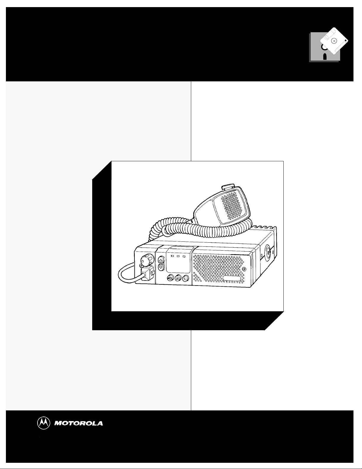
Radius GM300
RapidCall Signalling Reference
Mobile Radio
The Dealer’s Radio Service Software Manual
Radius Products Division
1-800-356-1520 (U.S.)
319-385-5395 (Outside U.S.)
6880902Z64-A
HVN8177
December 1993
Page 2

Software Rights Notice
This program is licensed to authorized Radius resellers and selected end users through an agreement with
Motorola Radius. This agreement gives you certain rights to use and copy this program at a single location.
The license allows one RSS per location. The RSS may be installed on any computer at that one location,
however, remote access off-site, such as with a modem, is not allowed under the license. Licensee (you) may
specify other locations in the agreement at the time the license is executed. A separate software package
must be purchased for each location.
Tampering with or modifying the RSS is not allowed under the terms of the license agreement.
If these terms are violated, Motorola reserves the right to revoke the license at any time.
Should you need additional subscriptions, contact Motorola Radius Division to purchase additional software subscriptions.
This Motorola product contains a copy of one or more items of Radio Service Software computer program(s) and may
contain documentation and material provided by Motorola in connection with the Radio Service Software computer
program(s) ("The Software"). The use of the software is governed by a License which has been granted to the software
purchaser ("Licensee") under the terms and conditions of the Radio Service Software License Agreement ("License
Agreement") entered into between the Licensee and Motorola.
In that License Agreement, Motorola and Licensee specifically agreed that Licensee may obtain such items of software
in the future, subject to the terms and conditions of the License agreement.
Motorola expressly reserves all rights in the software not expressly granted to the Licensee in the License issued pursuant to the terms and conditions of the License Agreement.
Computer Software Copyrights
The Motorola products described in this manual may include copyrighted Motorola computer programs stored in semiconductor memories or other
mediums. Laws in the United States and other countries preserve for Motorola certain exclusive rights for copyrighted computer programs, including the exclusive right to copy or reproduce in any form the copyrighted computer program. Accordingly, any copyrighted Motorola program contained in Motorola products described in this manual may not be copied nor reproduced in any manner without the express written permission of
Motorola. Furthermore, the purchase of Motorola products shall not be deemed to grant either directly or by implication, expressed or otherwise,
any license under the copyrights, patents or patent application of Motorola, except for the normal non-exclusive royalty fee to use that arises by
operation of law in the sale of a product.
Trademarks
MOTOROLA, Radius, Channel Scan, Quik Call II, MDC-1200, RapidCall, STAT-ALERT,
Private Line, and Digital Private Line are trademarks of Motorola, Inc.
PC XT/AT/Convertible and PS/2 Model 30/50/70 are trademarks of IBM Inc.
MSDOS and MS Windows are trademarks of Microsoft Corp.
Copyright Motorola, Inc. 1990, 1991, 1992, 1993. Printed in USA. All rights reserved.
Page 3

Dedicated to Radius dealers and servicers world-wide...
Earle L.
Nancy A.
Amy H.
Kim P.
Joe P.
Craig C.
Rick R.
Rod B.
Chris L
...and the following manual contributors:
Pam S.
Rafaela R.
SH
Joe C.
Paul B.
Larry Y.
Al M.
Kim L.
Kathy C.
Mark N.
Mike R.
Carol R.
Mike C.
Christine C.
Bob B.
Wolfgang R.
John O.
Heidi K.
Thank you for your contributions!
Page 4

Radius
Radius Products Division
Hwy 34 West
Mount Pleasant, IA 52641
USA
Page 5

Table of Contents
1
Introduction
1.1
Overview
1.2
Prerequisites
1.3
Using This Manual
1.4
Subscription Information
2
Tutorials
2.1
Overview
2.2
Programming Basic Radios
2.2.1 Scenario 2-2
2.2.2 Desired Features 2-3
2.2.3 Major Decisions Involved 2-3
2.2.4 Step-by-Step Programming Instructions 2-4
2.2.4.1 Read Current Radio’s Personality (Codeplug) 2-4
2.2.4.2 Program The Radio-Wide Features First 2-5
2.2.4.3 Program The Per-Mode Features 2-7
2.2.4.4 Program The Personality Into The Codeplug (Radio) 2-9
2.2.4.5 Save The Personality To An Archive File 2-10
2.2.4.6 Exit RSS. 2-10
Cloning Radios
2.3
2.3.1 Scenario 2-11
2.3.2 Desired Features 2-11
2.3.3 Major Decisions Involved 2-12
2.3.3.1 Pick Desired Archive File 2-12
2.3.4 Step-by-Step Specific Cloning Instructions 2-12
2.3.4.1 Read Source Archive File 2-13
2.3.4.2 Clone Current Radio From Archive File 2-13
2.3.4.3 Clone Remaining Radios 2-15
2.3.4.4 Exit RSS 2-15
1-1
2-1
1-1
1-2
1-2
1-4
2-1
2-2
2-11
3
Rapidcall Signalling
3.1
Overview
3.2
Format of This Chapter
3.3
Signalling System Features
3.4
MDC-1200 Signalling Systems (STAT-ALERT)
3.5
STAR Signalling System
3.6
Quik Call II Signalling Systems
3.7
DTMF Signalling Systems
October, 1996 6880902Z64-A
3-1
3-1
3-20
3-1
3-2
3-3
3-27
3-40
i
Page 6

Table of Contents GM300 RapidCall Radio Service Software Manual
Singletone Signalling Systems
3.8
3.9
DTMF/Phone Access Signalling Systems
4
Select V Signalling
4.1
Overview
4.2
Format of This Chapter
4.3
Select V Signalling System
4.4
Encode Sequence Definitions
4.5
Decode Sequence Definitions
5
Call List
5.1
Defining the Call List
5.2
Format of This Chapter
5.3
Call List Feature Definitions
6
RSS Functions
6.1
Define a Signalling System
6.2
RSS Functions
6.3
Format of This Chapter
6.4
RSS Function Definitions
4-1
5-1
5-1
6-1
6-1
3-60
3-66
4-1
4-1
4-2
4-21
4-26
5-1
5-2
6-1
6-1
6-2
7
Phone Memory Dialer
7.1
Programming the Phone Memory Dialer
7.2
Format of This Chapter
7.3
Phone Memory Dialer Feature Definitions
8
Signalling Radio-Wide
8.1
Radio Wide Signalling
8.1.1 Program Call List Features 8-1
8.1.2 Signalling Systems 8-1
Format of This Chapter
8.2
8.3
Signalling Radio-Wide Feature Definitions
9
Menus and Screens
9.1
Overview
9.2
Change/View Codeplug Menu
9.3
Encode/Decode/Radio-Wide
9-15
7-1
8-1
8-2
7-1
7-1
7-2
8-1
8-2
9-15
9-16
9-17
ii
6880902Z64-A October, 1996
Page 7

GM300 RapidCall Radio Service Software Manual Table of Contents
9.4
10
10.1
10.2
11
Signal Configuration
Appendices
Appendix A - Mixing Signalling Systems
Appendix B - Radio Personality Form
Glossary
9-18
AP-1
GL-1
AP-2
AP-4
October, 1996 6880902Z64-A
iii
Page 8

Table of Contents GM300 RapidCall Radio Service Software Manual
iv
6880902Z64-A October, 1996
Page 9

1
1
Introduction
1.1 Overview
Welcome to the world of two-way radio programming from Radius, a division of Motorola. This manual
is targeted for anyone who wants to program RapidCall features into the Radius GM300 mobile radio, or
make use of the Select V signalling standards. Feature programming, or customizing, personalizes a
radio for an individual customer's needs, resulting in radios with unique Òpersonalities.Ó
The Radius GM300 series of mobile radios has a unique set of RapidCall features, including:
❏
❏
Signalling capabilities
¥ MDC-1200
¥ Quik Call II
¥ STAR,
¥ DTMF
¥ DTMF Phone
¥ Singletone
Call Lists
These features make the Radius GM300 an ideal radio for commercial businesses and police and Þre protection services that use radios in their service vehicles.
How can Radius design radios with such a wide range of features and still offer radio servicers the ability to customize and personalize radios? The answer is in the modern microprocessor chip technology in the radio and
the use of Radius' Radio Service Software (RSS) - a computer program that, when interfaced with a radio,
electronically programs and personalizes a radio with a unique set of features for each individual customer. The RSS program is found on the diskettes included with this manual (Package HVN8177). The
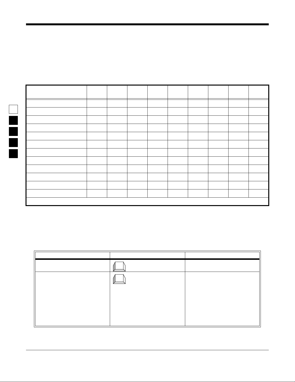
some of the features and functions available when using the RSS program are listed in Table 1-1:
October, 1996 6880902Z64-A
1-1
Page 10

Introduction GM300 RapidCall Radio Service Software Manual
Prerequisites
Table 1-1. RSS Programmable Features and Functions
1
GM300 RSS Programmable Features GM300 RSS Service Functions
Transmit (Tx) frequencies Reference oscillator alignment
Receive (Rx) frequencies Transmit deviation alignment
PL/DPL codes Transmit power alignment
Signalling system parameters* Replaced power ampliÞer calibration
Scan lists and scan options Replaced logic board calibration
Accessory connector deÞnition* Replaced RF board calibration
* 16-channel Model only
This radio customizing and servicing is accomplished by using a standard IBM-XT/AT (or compatible),
IBM convertible, or System/2 Model 30/50/70 computer.
Note: Prior to purchasing a computer, we recommend you test any computer's RSS ÒcompatibilityÓ by
connecting all the hardware, installing the software, starting the RSS and reading and writing data to
and from a radio. If problems occur, call the phone number on the front cover for help.
1.2 Prerequisites
To use RSS and to program the radios, we recommend a basic working knowledge of the following:
❏
Microcomputers.
❏
Microsoft Disk Operating System (MS-DOS), version 3.2 or later.
❏
The radio's available features (see Feature Chart in Basic Features section),
❏
The GM300 Study Guide, and the GM300 Operator's Manual.
This manual is written for both beginners and advanced users; the primary prerequisite for using RSS is
the desire to program and deliver an excellent radio to your customer.
1.3 Using This Manual
This manual is designed to teach basic feature programming and to speed up access to technical information. To facilitate access to information, we have included key words in the page headers, numerous
tables and lists, and a revised Table of Contents and reference sections. To help you better understand the
information presented, we have expanded the Glossary list and added a Tutorials section to get new
users started more quickly. Table 1-2 lists suggested ways to use this manual.
1-2
6880902Z64-A October, 1996
Page 11
GM300 RapidCall Radio Service Software Manual Introduction
Using This Manual
Table 1-2. How to Use this Manual
First Time User Occasional User Frequent User
1. Read the Introduction section (in
book 6880902Z36)
2. Read and do the steps in section
2,
Getting Started (in book
6880902Z36)
3. Do one or more of the tutorials.
4. Use the
abbreviations you donÕt understand
5. Know the phone number of a frequent user or Radius technical
support.
6. Do another tutorial within 48
hours of the Þrst one for better
memory retention
Glossary for terms and
1. Review Getting Started to set up
the hardware, install, start or
move around in the RSS
2. Decide what features you want
radio-wide and per-mode; write
them down.
3. To add more features to a radio,
either read in a archive Þle you
previously saved then for each
additional feature, use the
ence
sections to program the fea-
ture
4. For adding features, review the
Feature Chart , and use the Reference
sections as needed
Refer-
1
1. Decide what features you want
radio-wide and permode; write
them down
2. Decide whether to start from
scratch or to clone from an existing Þle.
3. Use sections 1, 2, and the appendixes only as needed
4. Find most of your information
from Sections 3 through 10 (Fanning or thumbing through the
reference sections may be all you
need.)
5. To install an RSS update or for
servicing, refer back to
6880902Z36.
The page layout and type selection is designed to speed up access to the information and to provide
visual clarity and distinction between certain types of information.
❏
Headers
The header area (top) of each page shows the name of the manual on the inside edge of the
page and a section and subsection name on the outside edge of the page.
Footers
❏
The footer area (bottom) of each page contains the page number on the outside edge of the
page and the manual number on the inside edge of the page for easy identiÞcation if a page
becomes separated from the original manual.
❏
Type Styles
Keyboard keys and words typed from the keyboard are shown in bold font. RSS menu and
screen names are shown in ALL CAPITAL LETTERS RSS Þeld names (features) are shown in
Initial Capital Letters.
❏
Tables
Tables are used abundantly to list steps and procedures.
❏
Figures
Figures can be drawings or pictures of hardware and equipment, screen-captured images of
RSS menus and screens, or computer-created graphics.
❏
A stop light represents an important warning.
October, 1996 6880902Z64-A
1-3
Page 12
1
Introduction GM300 RapidCall Radio Service Software Manual
Subscription Information
1.4 Subscription Information
Your RSS is part of a subscription. We shall keep you advised of changes and automatically mail revisions
throughout the life of the subscription.
A subscription is good for one site. Under the terms of your subscription, you may install the RSS on as
many personal computers as wanted at that one site. Another site location requires another subscription.
When contacting the Radius Distribution Center for your region of the world, you may need to refer to
your subscription model number. See Table 1-3 for your region and model number:
Table 1-3. Subscription and Support Group Numbers.
Subscription
Region/Location
Japan
U.S.
Canada
Australia
Europe
Germany
Rest of world
Model Number Support Group
H5106
H5028
H5041
H5044
H5114
H5133
H5030
Radius North America Distribution Center,
1-800-356-1520
Technical Hotline Center, 1-800-663-1771
Local Radius Dealer*
Local Radius Dealer*
Radius North America Distribution Center,
1-319-385-5395
* Your local dealer has access to Motorola technical help .
1-4
6880902Z64-A October, 1996
Page 13

2
2
Tutorials
2.1 Overview
The tutorials in this section can be used to personalize radios for customers. We have created an imaginary scenario to demonstrate the need for radios programmed with different features for various applications. In each tutorial, the setting is the Longwood Hotel and Convention Center, a full-service hotel and
convention facility specializing in large-scale corporate meetings. The Longwood Center must prepare
for a major upcoming radio convention which will offer extended lodging, exposition and banquet facilities. There are three major communication requirements involved in the setup of the convention which
fall into the following areas:
❏
❏
❏
Convention setup and maintenance staff
Needs radios to coordinate forklift and towing services involved in preparing the exposition
display ßoor.
Security staff
Needs radios to provide crowd control and security force patrol at the exposition center, at the
hotel, in the parking garage and on the complex grounds.
Banquet and food commissaries
Needs radios to provide internal and external coordination of catering and banquet
resources using a van ßeet.
The Þrst tutorial (Programming Basic Radios) walks you through the steps of programming a new, basic
8-channel radio and takes approximately 45 minutes to complete. An on-line demo version of this tutorial is on the RSS demo diskette. To view it, type DEMO1. To quit the demo, press the Esc or Del key. We
suggest you view the demo after reading section 2.2.4 of the tutorial.
The second tutorial (Cloning Radios) goes much faster, and involves cloning (copying) the personality
data from an archive Þle of one pre-programmed radio to other radios. Cloning is used when there is a
need for multiple radios equipped with the same radio features and functions.
Each tutorial provides the following:
1. Sets the scene
2. Lists the desired features for the particular application
3. Gives an overview in a list format of the major steps involved in programming the radio
4. Walks you through the speciÞc steps to program the features into the radio.
The tutorials assume that RSS is running and the MAIN MENU is displayed. If the MAIN MENU is not
displayed, refer to Table 2-1 on page 2-2.
October, 1996 6880902Z64-A
2-1
Page 14
Tutorials GM300 RapidCall Radio Service Software Manual
Programming Basic Radios
For all tutorials, F1 displays help information corresponding to the current highlighted Þeld or current
screen. F10 backs you out of RSS one menu level at a time. Esc goes directly to the MAIN MENU.
Table 2-1. Steps to Bring Up RSS MAIN MENU
Using Two Diskette Drives Using Hard Drive
2
1. Assemble, connect and power up the hardware 1. Assemble, connect and power up the hardware
2. Load DOS from drive A. After the computer has
successfully booted, the prompt will be ÒA:Ó.
3. Insert the Òworking copyÓ RSS diskette into drive
B, then move to drive B by typing the command
below followed by
kettes, insert diskette #1 Þrst.)
B:
4. Type the command below, followed by
GM300
(If using 5.25Ó diskettes, remove diskette #1 and
insert diskette #2 when the RSS instructs you.)
5. If this is the Þrst time this RSS version is started
and the
appears, you can either skip this screen by pressing
archive path, display colors and choice of COM
ports, then save the conÞguration (
the screen (
6. Press any key at the
7. The
CONFIGURE COMPUTER SCREEN
F10
, or work through it to set up your
F10
MAIN MENU
Return
(If using 5.25Ó dis-
Return
:
F8
) and exit
).
Banner
appears. 7. The
screen. 6. Press any key at the
and the computer.
2. After the computer has successfully booted, the
prompt will be ÒC:Ó.
3. If you have not yet installed the latest RSS version, see the Starting RSS subsection to make a
backup RSS copy and to install it on your hard
disk.
4. Type the command below, followed by
GM300
5. If this is the Þrst time this RSS version is started
and the
appears, you can either skip this screen by pressing
archive path, display colors and choice of COM
ports, then save the conÞguration (
the screen (
CONFIGURE COMPUTER SCREEN
F10
, or work through it to set up your
F10
).
Banner
screen.
MAIN MENU
appears.
Return
F8
) and exit
:
2.2 Programming Basic Radios
This tutorial gives step-by-step instructions for programming the 8-channel Radius GM300 mobile radio.
2.2.1 Scenario
The Longwood Hotel and Convention Center's setup and maintenance staff needs a basic 8-channel
radio to coordinate the forklift and towing services required in the setup of the exposition's display ßoor.
A central dispatcher will direct the setup activities by communicating with the mobile forklift and truck
drivers.
2-2
6880902Z64-A October, 1996
Page 15

GM300 RapidCall Radio Service Software Manual Tutorials
Programming Basic Radios
2.2.2 Desired Features
The convention setup and maintenance radios will need the following features:
❏
A Transmit Frequency
❏
A Receive Frequency
❏
Private Line/Digital Private Line (TPL/DPL) Codes
❏
Carrier Squelch
❏
Time-Out Timer (TOT)
2.2.3 Major Decisions Involved
To program the desired features above, the approach with the RSS will be:
❏
Decide which radio model to use.
❏
Decide which frequencies to use.
❏
Pick the number of modes (channels) desired.
❏
Decide which feature systems to use (basic, scan, signalling).
❏
Decide which features to program radio-wide (all channels).
❏
Decide which features to program per-mode (individual channels only).
❏
Do the step-by-step speciÞc programming instructions.
2
October, 1996 6880902Z64-A
2-3
Page 16
Tutorials GM300 RapidCall Radio Service Software Manual
Programming Basic Radios
2.2.4 Step-by-Step Programming Instructions
Table 2-2 is a chart of the desired features for each mode of the radio being programmed in this tutorial.
Check them off as you do them in the sections to follow. See Appendix B for a blank form you can use for
future radios.
Table 2-2. Radio Personality Chart
2
Feature Name
Tx Frequency
Rx Frequency
PL Codes
Squelch
Time Out Timer (TOT)
Busy Channel Lockout
Tx Inhibit on Busy
Signalling Systems
Local/Distance
KEY:
✔
= original personality
2.2.4.1
Read Current Radio’s Personality (Codeplug)
Before programming the radio with the radio with some features, you must read and access the current
radio's (codeplug data). Refer toTable 2-3.
Radio
Wide
Mode 1
#_____
✚
= feature added, 1
Mode 2
#_____
st
update
Mode 3
#_____
✚✚
Mode 4
#_____
= feature added, 2
Mode 5
#_____
nd
update
Mode 6
#_____
Mode 7
#_____
■
= feature removed
Mode 8
#_____
Instruction What to type What it does or means
1. Go to
2. Get radioÕs current codeplug
GET/SAVE
data
2-4
Table 2-3. Steps to Read a RadioÕs Personality (Codeplug)
menu Press
F3
F2
to the
At the
execute the function. In the Instruction Area of the screen, the message
ÒAccessing Serial BusÓ will ßash a
few times while the RSS is retrieving the radioÕs codeplug data. If it
does not, make sure that all the
cables are properly connected and
that both the radio and RIB are
powered up.
6880902Z64-A October, 1996
F3
at the
GET/SAVE
GET/SAVE
MAIN MENU
Menu.
menu, press
to get
F2
to
Page 17
. )
GM300 RapidCall Radio Service Software Manual Tutorials
Programming Basic Radios
2.2.4.2
1. Go to
2. Go to
3. Select choice.
4. Go to
5. Select choice
Program The Radio-Wide Features First
After the radio's codeplug data is read, the RSS allows you to access the CHANGE/VIEW menu. From
here you can program the features you want on every channel, and the ones you want common to all
channels. First, youÕll program the features that affect the radio as whole, or radio-wide features. Refer to
Table 2-4.
Table 2-4. Steps to Program Radio-Wide Features
Instruction What to Type What it does or means
CHANGE/VIEW
Radio-Wide
menu. (Press Esc to back up to
screen. At the
Esc
F2
F4
MENU
MENU
Menu.
F2
The
be highlighted.
Press
to see the
CHANGE/VIEW
to see the
TOT Rekey Time
Radio-Wide
MAIN
F4
at the
MAIN
CHANGE/VIEW
menu, press
screen.
Þeld should
↓
TOT Rekey Time
Tab
Pressing
to the next Þeld
Tab
advances the prompt
↓
2
6. Go to
7. Select Choice.
8. Go to
9. Select Choice
Forced Monitor
Handset
Þeld. Pressing
Tab
to the next Þeld.
↓
Þeld. Pressing
Tab
to the next Þeld.
↓
Tab
advances the prompt
Tab
advances the prompt
October, 1996 6880902Z64-A
2-5
Page 18
Tutorials GM300 RapidCall Radio Service Software Manual
Programming Basic Radios
Table 2-5. Steps to Program Radio-Wide Scan Features
Instruction What to Type What it does or means
1. Go to
2. Select Choice
SCAN OPTIONS
screen From the
F7
F7 to see the
The
PRI Sampling Method
should be highlighted.
↓
RADIO-WIDE
Scan Options
screen press
screen.
Þeld
2
3. Go to
4. Select Choice
5. Go to
6. Select Choice
7. Go to
8. Select Choice
9. Go to
10.Select Choice
11.Go to
12.Select Choice
13.Go to
14.Select Choice
Scan Speed
User Pri2 Allowed
PRI Sampling Rate
PRI Channel Tone
Scan Hang Time
Scan Talk Back
Þeld Pressing
Tab
to the next screen.
↓
Þeld Pressing
Tab
to the next screen.
↓
Þeld Pressing
Tab
to the next Þeld.
↓
Þeld Pressing
Tab
to the next Þeld.
↓
Þeld Pressing
Tab
to the next Þeld.
↓
Þeld Pressing
Tab
to the next Þeld.
↓
Tab
advances the prompt
Tab
advances the prompt
Tab
advances the prompt
Tab
advances the prompt
Tab
advances the prompt
Tab advances the prompt
15.Return to CHANGE/VIEW menu From the Scan Options screen press
F10 to return to the Radio-Wide
screen, then press F10 to return to
the CHANGE/VIEW menu.
2-6
F10 F10
6880902Z64-A October, 1996
Page 19

GM300 RapidCall Radio Service Software Manual Tutorials
Programming Basic Radios
2.2.4.3
Program The Per-Mode Features
Now that the radio-wide features are programmed, you can now program the per-mode features. Figure
shows the MODE CONFIGURATION screen. You will become very familiar with this screen, as you will
change the Þeld options on this screen for each mode you program on a Òper-modeÓ basis.
2
Figure 2-1. Per-Mode Features on MODE Screen
To keep track of your progress, use the Radio Personality Form in Appendix B to check off the features
for each mode after you program them. In Table 2-6, the Enter or Return key can be used instead of the
Tab key.
October, 1996 6880902Z64-A 2-7
Page 20

2
Tutorials GM300 RapidCall Radio Service Software Manual
Programming Basic Radios
Table 2-6. Steps to Program Per-Mode Features
What to
Instruction
1. Go to CHANGE/VIEW menu (Press Esc to back up to MAIN MENU.) Press F4 at the
2. Go to MODE CONFIG menu At CHANGE/VIEW menu, press F5 to go to MODE
3. Go to Name Þeld The prompt will be on the Name Þeld when you move
4. Select a Name
5. Go to Rx Frequency Þeld (The
Type Þeld cannot be accessed at
this time).
6. Select an Rx Frequency A frequency number can be typed in or selected.
7. Go to Tx Frequency Þeld Pressing Tab advances the prompt to the next Þeld.
8. Select a Tx Frequency A frequency number can be typed in or selected.
9. Go to Rx Squelch type Þeld Pressing Tab advances the prompt to the next Þeld.
type What it does or means
F4
F5
Tab
Tab
Tab
MAIN MENU to see the CHANGE/VIEW Menu.
CONFIGURATION menu. You will be at mode 1.
to this screen, as it is the Þrst Þeld.
Pressing Tab advances the prompt to the next Þeld.
10.Select an Rx Squelch type
11.Go to Rx Squelch Code Þeld Pressing Tab advances the prompt to the next Þeld.
12.Select an Rx Squelch Code
13.Go to Rx Signalling System Þeld. Pressing Tab advances the prompt to the next Þeld.
14.Select an Rx Signalling System.
15.Go to Rx Signalling System
Name Þeld.
16.Select an Rx Signalling System
Name
17.Go to Tx Squelch Type Þeld Pressing Tab advances the prompt to the next Þeld.
18.Select a Tx Squelch Type
19.Go to Tx Squelch Code Þeld Pressing Tab advances the prompt to the next Þeld.
20.Select a Tx Squelch Code
21.Go to Tx Signalling System Þeld Pressing Tab advances the prompt to the next Þeld.
↓
Tab
↓
Tab
↓
Tab
↓
Tab
↓
Tab
↓
Tab
Pressing Tab advances the prompt to the next Þeld.
22.Select a Tx Signalling System
23.Go to Tx Signalling System
Name Field
↓
Tab
Pressing Tab advances the prompt to the next Þeld.
2-8 6880902Z64-A October, 1996
Page 21
GM300 RapidCall Radio Service Software Manual Tutorials
Programming Basic Radios
Table 2-6. Steps to Program Per-Mode Features (ContÕd.)
What to
Instruction
24.Select a Tx Signalling System
Name Field.
25.Go to Busy Channel Lockout
Þeld
26.Select Busy Channel Lockout
choice
27.Go to Local/Distance Þeld Pressing Tab advances the prompt to the next Þeld.
28.Select Local/Distance choice
type What it does or means
↓
Tab
Pressing Tab advances the prompt to the next Þeld.
↓
Tab
↓
2
2.2.4.4
29.Go to Time Out Timer Þeld Pressing Tab advances the prompt to the next Þeld.
30.Select Time Out Timer choice
31.Program the next mode Repeat steps 4-30 for each mode (channel).
32.Create additional mode Press F8 at the MODE CONFIGURATION menu to go
Tab
↓
F4
F4
↓
to the MODE UTILITY screen, then press the down
arrow key to scroll through the mode utility list until
the ADD mode choice appears.
Program The Personality Into The Codeplug (Radio)
Now that you have set values for all the features you want, it is time to actually program them into the
radio. Programming the personality into the radio's codeplug must be done after creating or editing the
personality of a radio or else the changes will be lost.
Note: Make sure that the radio is connected to the Radio Interface Box (RIB) and that both the RIB and
radio are powered up before pressing F8. On newer RIBs that have a built-in battery supply, make sure
the power LED is on. If you have serial bus errors or other warnings, try a fresh RIB battery even though
the power LED may be on.
October, 1996 6880902Z64-A 2-9
Page 22
2
Tutorials GM300 RapidCall Radio Service Software Manual
Programming Basic Radios
Table 2-7. Saving Changes to the Radio
Instruction What to Type What it does or means
1. Go to GET/SAVE menu (Press Esc to back up to MAIN
2. Save changes Saves changes to the radio. If you
F3
F8
MENU.) Press F3 at the MAIN
MENU to see the GET/SAVE menu.
have any errors, refer to Appendix
A of the GM300 RSS manual for
troubleshooting guidance.
When programming or calibrating a radio DO NOT disconnect the radio from the RIB when the computer is communicating with the radio - it may leave the radio in an inoperable state. The only recommended time to disconnect the radio is at the MAIN MENU or GET/SAVE screens.
2.2.4.5
Save The Personality To An Archive File
You have just saved the personality to the radio, but it is important to save it on disk too. Below are the
steps to save the radio's personality to an archive Þle and a backup Þle.
2.2.4.6
Exit RSS.
You now have a foundation for programming more radios. If you don't want to proceed to the next tutorial, Cloning Radios, then use the steps outlined in Table 2-8 to exit RSS. To retain a good portion of what
you have learned so far, please review this material or program another radio within 48 hours.
Table 2-8. Steps to Exit the RSS
Instruction What to type What it does or means
1. Go to MAIN MENU Press Esc to back up to MAIN
2. Exit to DOS Press F10 twice to exit to DOS.
Esc
F10 F10
MENU.
2-10 6880902Z64-A October, 1996
Page 23
GM300 RapidCall Radio Service Software Manual Tutorials
Cloning Radios
2.3 Cloning Radios
To clone, radios must be of the same model type and version.
Table 2-9. Steps to Save Radio Personality to Archive and Backup Files
Instruction What to type What it does or means
1. Go to GET/SAVE menu (Press Esc to back up to MAIN
2. Go to SAVE ARCHIVE FILE Press F7 at GET/SAVE to see SAVE
3. Specify archive Þle path C:\MRSS\GM300\ARCHIVE This is where we recommend you
4. Specify backup path B:\ Specify the root directory of the dis-
5. Save the Þle Pressing F8 at the SAVE ARCHIVE
6. Insert formatted diskette Put a formatted diskette (or use
7. Save backup Þle After saving the archive Þle, the RSS
F3
F7
F8
F8
MENU.) Press F3 at the MAIN
MENU to see the GET/SAVE menu.
ARCHIVE FILE screen. This dis-
plays the archive diskette drive and
path name, current model number,
current radio serial number, and
customer ID. If there is no customer
ID, it can be added at this time.
save your radio personality archive
Þles for GM300 radios. Press F2 to
change/edit the archive Þle path. If
no archive path speciÞed, then type
in desired path name.
kette inserted in drive B to be the
backup Þle location.
FILE screen saves the data in an
archive Þle speciÞed above. (F2
allows you to change the disk path
and drive name.)
your existing archive Þle diskette)
into drive A so the RSS will save
your backup archive Þle.
will ask for the backup diskette if it
is not already inserted into the
drive. Follow the instructions.
2
2.3.1 Scenario
To make the best use of their time, the Longwood Hotel and Convention Center's setup and maintenance
staff will need at least two tow trucks and two forklifts equipped with identical Radius GM300 mobile
radios, as their duties are very similar.
2.3.2 Desired Features
The desired features are the exact same ones listed in the previous tutorial.
October, 1996 6880902Z64-A 2-11
Page 24

Tutorials GM300 RapidCall Radio Service Software Manual
Cloning Radios
2.3.3 Major Decisions Involved
The major steps for cloning in this tutorial are reduced from the six steps in the Þrst tutorial to three steps
here, as most of the questions were answered by the decision to have identical radio personalities for all
setup and maintenance operations.
To program the cloned radio, the approach will be:
❏ Pick Archive File.
❏ Decide Whether to Change IDs.
❏ Decide How Many Radios to Clone.
2
2.3.3.1
Pick Desired Archive File
To clone, the radios must be from the same product family, must be of the same model type and product
vintage. In this case, you will use the archive Þle created and saved in the Þrst tutorial, A999999.999.
2.3.4 Step-by-Step Specific Cloning Instructions
In this subsection, you will:
❏ Read (get) into the RSS the speciÞc Þle you want to clone from (source Þle),
❏ Clone that source Þle into the current radio's codeplug (target),
❏ Clone the remaining two radios the same way, and then
❏ Exit RSS.
2-12 6880902Z64-A October, 1996
Page 25

GM300 RapidCall Radio Service Software Manual Tutorials
Cloning Radios
2.3.4.1
2.3.4.2
Read Source Archive File
2
Figure 2-2. Reading (Getting) an Archive File from Disk
Clone Current Radio From Archive File
Radio codeplugs consist of both personality and tuning data. Cloning allows you to ÒmergeÓ two codeplugs together. The archive Þle or radio with the desired personality is called the source Þle or source radio.
The other Þle is referred to as the target radio. The result is an image that can be programmed into a radio
and/or saved to an archive Þle. This image will have the source codeplug's personality, yet the tuning
data of the target codeplug remains unchanged. In this tutorial, the source personality is the Þle saved in
the Þrst tutorial, and the target radios are the three radios not yet programmed. To clone radios, follow
the procedures listed in Table 2-10. To clone additional radios, use Table 2-11.
Note: The IDs for MDC-1200, Quik Call II, DTMF, etc. must be changed manually if you want to have
unique IDs. You may do this by going to CHANGE/VIEW immediately after cloning each radio.
October, 1996 6880902Z64-A 2-13
Page 26
2
Tutorials GM300 RapidCall Radio Service Software Manual
Cloning Radios
Table 2-10. Steps to Clone Radios
Instruction What to type What it does or means
1. Go to GET/SAVE menu (Press Esc to back up to MAIN
2. Go to GET ARCHIVE FILE Press F3 at GET/SAVE menu to go
3. Type in path name C:\MRSS\GM300\ARCHIVE This tells RSS to display the Þle
4. Select desired Þle Press Tab until the A9999999.999 Þle
5. Get selected Þle Get the selected (highlighted) Þle.
F3
F3
Tab
F8
MENU.) Press F3 at the MAIN
MENU to see the GET/SAVE menu.
to GET ARCHIVE FILE screen. (A
list of Þles is displayed which look
like serial numbers) that the RSS
program found under the directory
path shown.)
names found in this directory. You
will see the Þle named
A9999999.999 that you saved in the
Þrst tutorial.
is highlighted.
6. Connect target radio Assemble the hardware and connect
the radio you want cloned.
7. Save source into target radio After Step 5 you should be back at
8. Disconnect radio When Step 7 is Þnished, you can
9. Proceed to step 1 in next table.
F5 F5
the GET/SAVE menu. Press F5 from
GET/SAVE to clone the current
radioÕs codeplug with the selected
source ÞleÕs personality. The cloning
process will check for compatibility
of the two radios automatically. You
will receive an error message if cloning cannot be performed. If for any
reason the radios cannot be cloned,
an error message will appear. Check
all connections or refer to Appendix
A (Error Code Explanations) and B
(Troubleshooting Problems).
disconnect the radio. In a matter of
seconds the second radio was
cloned. Disconnecting the radio
should only be done at the GET/
SAVE menu or the MAIN MENU, or
the radio may be left in an inoperable state.
Make sure that you go back and
manually change the ID of every
radio that you have cloned (if you
want their IDs to be different from
that of the original radio).
2-14 6880902Z64-A October, 1996
Page 27

GM300 RapidCall Radio Service Software Manual Tutorials
Cloning Radios
2.3.4.3
Clone Remaining Radios
Table 2-11. Cloning Additional Radios
Instruction What to type What it does or means
1. Do Steps 1-5 in Table 2-3. Do steps 1-5 in Table 2-10 on page 2-
14.
2. Connect next target radio Connect cable from RIB to the radio.
3. Clone the radio Press F5 at the GET/SAVE menu to
4. Disconnect radio When Step 3 is Þnished, disconnect
5. Clone remaining radios Repeat Steps 2-4 for the last two
F5 F5
clone the radio. This saves (reads)
the source Þle into the current radio.
The cloning process will check for
compatibility of the two radios
automatically. You will receive an
error message if cloning cannot be
performed.
the radio.
Make sure that you go back and
manually change the ID of every
radio that you have cloned (if you
want their IDs to be different from
that of the original radio)
radios. If for any reason the radios
cannot be cloned, an error message
will appear. Check all connections
or refer to Appendix A (Error Code
Explanations) and B (Troubleshooting Problems).
2
2.3.4.4
Exit RSS
To exit RSS, follow the steps in Table 2-8.
In a matter of minutes three more radios were programmed identically to the Þrst one. Additional features can be added by following the programming procedures in the corresponding reference pages in
the Reference sections that follow.
October, 1996 6880902Z64-A 2-15
Page 28

2
Tutorials GM300 RapidCall Radio Service Software Manual
Cloning Radios
2-16 6880902Z64-A October, 1996
Page 29

3
3
Rapidcall Signalling
3.1 Overview
The RapidCall Signalling option allows you to create up to 32 different signalling systems that are slaved
to a receive or transmit frequency. The variety of signalling formats available makes this the most ßexible
signalling radio in the marketplace. The formats are:
❏
❏
❏
❏
❏
❏
MDC-1200 (STAT-ALERT)
Quik Call II
STAR
DTMF
Singletone
DTMF/Phone Access
Each signalling system has a number of parameters that may be changed on the SIGNALLING CONFIGURATION screens. In most cases the default values will not have to be changed. A description of each
parameter and how it affects each signalling format follows.
For some features you will need to use other screens. Control or base units may need to encode calls or
display IDs. If so, you can create a list on the CALL LIST CONFIGURATION screen. When creating a Call
List, you will also need to edit information on the RADIO WIDE CONFIGURATION screen. For features
such as emergency you will need to edit information on the RADIO WIDE CONFIGURATION screen.
3.2 Format of This Chapter
Only one feature or function is shown on a page. On each reference page you will Þnd a standard page
layout with consistent categories of information. Below is a list and explanation of these categories. The
categories marked with an asterisk (*) appear on every reference page. The other categories appear only
when they apply to the speciÞc feature.
❏
FEATURE NAME*
IdentiÞes the name of the reference feature.
❏
RSS LOCATION*
Provides a quick visual map of where you'll Þnd a particular feature within the RSS, showing
the keys to press to arrive at the feature's or function's screen location. More details of this
map follow in the PROGRAMMING PROCEDURE section.
❏
DEFINITION*
Summarizes the feature's function - it deÞnes and brießy explains the feature.
October, 1996 6880902Z64-A
3-1
Page 30
3
Rapidcall Signalling GM300 RapidCall Signalling Reference
Signalling System Features
❏
❏
❏
❏
❏
❏
❏
DEFAULT/CHOICES*
IdentiÞes and explains both the default value the feature is automatically set to (with no user
input) and the other available choices a user can select.
DEPENDENCIES
I dentiÞes items that have a direct impact or inßuence upon the feature.
EXCEPTIONS
IdentiÞes when the general rules concerning a feature may not apply.
RECOMMENDATIONS
Provides advice for the most common applications and uses, and informs you when things
work best.
WARNINGS
IdentiÞes areas of caution and critical concerns. Be sure to read and act upon warnings. They
are more serious in nature than IMPORTANT NOTES.
IMPORTANT NOTES
Explains important issues to consider.
PROGRAMMING PROCEDURES*
Summarizes how to access and change a given feature. It explains the RSS LOCATION mapping in more detail.
3.3 Signalling System Features
The table below lists the features available for each signalling system.
Table 3-1. Signalling System Features
MDC
1200 STAR
Data Operated Squelch X
Radio Check X
PTT ID X X X X
Emergency Alarm X X
Call Alert X X X
Voice Selective Call X X X
Horn/Lights X X X
Repeater Access X
Memory Dial X
Access/Deaccess Codes X
ID Decode Display X
QUIK
CALL II DTMF
SINGLE
TONE
DTMF
PHONE
3-2
6880902Z64-A October, 1996
Page 31

3
GM300 RapidCall Signalling Reference Rapidcall Signalling
MDC-1200 Signalling Systems (STAT-ALERT)
3.4 MDC-1200 Signalling Systems (STAT-ALERT)
MDC-1200 is a Motorola proprietary signalling format. It is a binary format using a 1200 baud Minimum
Shift Keying modulation. The features available with MDC-1200 signalling are:
❏
Data Operated Squelch
❏
Radio Check
❏
PTT ID
❏
Emergency Alarm
❏
Call Alert
❏
Voice Selective Call
❏
Horn/Lights
❏
ID Decode Display
Please note: Voice Selcall is an inherent feature of MDC-1200.
The following pages contain descriptions of the parameters that may be modiÞed in a MDC-1200 system.
October, 1996 6880902Z64-A
3-3
Page 32

Rapidcall Signalling GM300 RapidCall Signalling Reference
MDC-1200 Signalling Systems (STAT-ALERT)
Ack Pretime
3
F4
➠
CHANGE/
VIEW
RSS LOCATION
DEFINITION
MAIN
MENU
The delay period from when the radio receives a call to when it starts the
Acknowledge (Ack) sequence.
DEFAULT/CHOICES Default: 0.4 seconds
Choices: 0.2 - 2.0 seconds
DEPENDENCIES
Acks are sent in response Call Alerts, Emergencies, Radio Checks, and Voice
Selective calls.
EXCEPTIONS
IRECOMMENDATIONS
Group calls do not expect an Ack.
Ack Pretimes on simplex systems should be the same as Pretime. If using repeaters with at least a short hang time, then Ack Pretime can be made signiÞcantly
shorter.
SEE ALSO
Pretime, Acknowledge
PROGRAMMING PROCEDURE
1.
Press F4 at the MAIN MENU to get to the
CHANGE/VIEW CODEPLUG MENU .
F7
SIGNAL
CONFIG
➠
4. Select the desired MDC-1200 signalling system by:
a. Pressing
b. Pressing
displayed.
F7
➠
F8
to add a system.
F3
or
F4
until the desired system is
SIGNAL
SYSTEM
Tab
➠
Ack Pretime
Field
3-4
2.
At the CHANGE/VIEW CODEPLUG MENU ,
press F7 to get to the SIGNAL CONFIGURA-
TION menu.
3.
At the SIGNAL CONFIGURATION menu, press
F7 to get to the SIGNALLING SYSTEM screen.
5.
Press the Tab or Enter/Return key until the
ield
Ack Pretime f
6.
Use the ↑ ↓ arrow keys to select choice.
6880902Z64-A October, 1996
is highlighted.
Page 33

MAIN
MENU
➠
F4
➠
F7
CHANGE/
VIEW
CONFIG
SIGNAL
SYSTEM
SIGNAL
➠
Tab
➠
F7
Alert Tone
Reset Field
GM300 RapidCall Signalling Reference Rapidcall Signalling
MDC-1200 Signalling Systems (STAT-ALERT)
Alert Tone Reset
RSS LOCATION
DEFINITION
Determines how the audible alert tone will be reset (silenced).
DEFAULT/CHOICES Default: Manual
Choices:
Automatic
■
Automatic
The alert tone will only sound once and then will be automatically reset.
Manual
The alert tone will repeat every 10 seconds and MUST be manually reset by the radio operator pressing any button, usually the
PTT.
DEPENDENCIES
Alert tones accompany Call Alert, Call Alert with Voice and Emergency Transmissions. Alert tone for reset applies only to Call Alert or Call Alert with Voice. It
does NOT apply to received emergency calls.
RECOMMENDATIONS
If this feature is set to AUTOMATIC, then 4 quick beeps will be heard after a Call
alert. This is the closest operation to a tone and voice pager.
SEE ALSO
Call Type
PROGRAMMING PROCEDURE
1.
Press F4 at the MAIN MENU to get to the
CHANGE/VIEW CODEPLUG MENU .
■
Manual
4. Select the desired MDC-1200 signalling system by:
a. Pressing
b. Pressing
displayed.
F8
to add a system.
F3
or
F4
until the desired system is
3
2.
At the CHANGE/VIEW CODEPLUG MENU ,
press F7 to get to the SIGNAL CONFIGURA-
TION menu.
3.
At the SIGNAL CONFIGURATION menu, press
F7 to get to the SIGNALLING SYSTEM screen.
October, 1996 6880902Z64-A
5.
6.
Press the Tab or Enter/Return key until the
Alert Tone Reset f
Use the ↑ ↓ arrow keys to select choice.
ield
is highlighted.
3-5
Page 34

Rapidcall Signalling GM300 RapidCall Signalling Reference
MDC-1200 Signalling Systems (STAT-ALERT)
3
Call T
RSS LOCATION
ype
MAIN
MENU
F4
➠
CHANGE/
VIEW
F7
➠
SIGNAL
CONFIG
F7
➠
SIGNAL
SYSTEM
Tab
➠
Call Type
Field
DEFINITION Determines what response a radio makes when selectively called with a Call
Alert.
DEFAULT/CHOICES Default: Call Alert
Choices: ■ Call Alert ■ Call Alert/Voice
Call Alert Leaves a visual/audible indication ONLY. The indicating
LEDs repeat until any button is pressed on the radio.
Call Alert/Voice Leaves a visual/audible indication and unmutes the radio so
the caller can leave an audible message. Both the light/tone
indications repeat until any button is pressed on the radio.
IMPORTANT NOTE Remember to enable Voice Selcall Encode and/or Call Alert Encode from the
SIGNALLLING RADIO-WIDE CONFIGURATION screen for the encoding (base)
radio.
SEE ALSO Alert Tone Reset
PROGRAMMING PROCEDURE
1. Press F4 at the MAIN MENU to get to the
CHANGE/VIEW CODEPLUG MENU.
2. At the CHANGE/VIEW CODEPLUG MENU,
press F7 to get to the SIGNAL CONFIGURA-
TION menu.
3. At the SIGNAL CONFIGURATION menu, press
F7 to get to the SIGNALLING SYSTEM screen.
4. Select the desired MDC-1200 signalling system by:
a. Pressing F8 to add a system.
b. Pressing F3 or F4 until the desired system is
displayed.
5. Press the Tab or Enter/Return key until the
Call Type field is highlighted.
6. Use the ↑ ↓ arrow keys to select choice.
3-6 6880902Z64-A October, 1996
Page 35

GM300 RapidCall Signalling Reference Rapidcall Signalling
MAIN
MENU
➠
F4
➠
F7
CHANGE/
VIEW
CONFIG
SIGNAL
SYSTEM
SIGNAL
➠
Tab
➠
F7
Console
Field
MDC-1200 Signalling Systems (STAT-ALERT)
Console
RSS LOCATION
DEFINITION Designates the radio as the Console Radio (Control Unit). When enabled, this
radio is to prepared to receive, display and acknowledge Emergency Alerts.
DEFAULT/CHOICES Default: N
Choices: ■ Y ■ N
IMPORTANT NOTE There must be an emergency switch connected to the accessory connector to clear
emergencies on the console radio. Clearing an emergency is a two-step process:
Þrst, press any button to silence the emergency beeps, next, press the emergency
switch to clear the display.
WARNING The radio displays one emergency from the same radio unit in any given 5 minute
period. It will, however, acknowledge repeated emergencies from a single unit.
SEE ALSO Horn/Lights
PROGRAMMING PROCEDURE
1. Press F4 at the MAIN MENU to get to the
CHANGE/VIEW CODEPLUG MENU.
2. At the CHANGE/VIEW CODEPLUG MENU,
press F7 to get to the SIGNAL CONFIGURA-
TION menu.
3. At the SIGNAL CONFIGURATION menu, press
F7 to get to the SIGNALLING SYSTEM screen.
3
4. Select the desired MDC-1200 signalling system by:
a. Pressing F8 to add a system.
b. Pressing F3 or F4 until the desired system is
displayed.
5. Press the Tab or Enter/Return key until the
Console field is highlighted.
6. Use the ↑ ↓ arrow keys to select choice.
October, 1996 6880902Z64-A 3-7
Page 36

Rapidcall Signalling GM300 RapidCall Signalling Reference
MDC-1200 Signalling Systems (STAT-ALERT)
Decode Display
3
RSS LOCATION
MAIN
MENU
F4
➠
CHANGE/
VIEW
F7
➠
SIGNAL
CONFIG
F7
➠
SIGNAL
SYSTEM
Tab
➠
Decode Display
Field
DEFINITION Indicates that the radio displays the ID of the transmitting radio provided it Òrec-
ognizesÓ an ID that is contained in its call list. Allows display of PTT IDs and if
programmed to receive Call Alerts and Voice Selcalls, displays senderÕs ID.
DEFAULT/CHOICES Default: Y
Choices: ■ N ■ Y
IMPORTANT NOTE The control unit must be programmed with a Call List containing the 4 digit ID of
each unit in its ßeet as well as the designated 2 digit ÒDisplay NameÓ for the radio
ID. Normally, ÒÞeldÓ units are not programmed to send selective calls. However,
they can be programmed so that the control unit receiving the call will alternatively display both letters, such as CA (Call Alert), and the radio ID numbers.
SEE ALSO Call List, Call Alert, Console
PROGRAMMING PROCEDURE
1. Press F4 at the MAIN MENU to get to the
CHANGE/VIEW CODEPLUG MENU.
4. Select the desired MDC-1200 signalling system by:
a. Pressing F8 to add a system.
b. Pressing F3 or F4 until the desired system is
displayed.
2. At the CHANGE/VIEW CODEPLUG MENU,
press F7 to get to the SIGNAL CONFIGURATION menu.
3. At the SIGNAL CONFIGURATION menu, press
F7 to get to the SIGNALLING SYSTEM screen.
5. Press the Tab or Enter/Return key until the
Decode Display field is highlighted.
6. Use the ↑ ↓ arrow keys to select choice.
3-8 6880902Z64-A October, 1996
Page 37

GM300 RapidCall Signalling Reference Rapidcall Signalling
MAIN
MENU
➠
F4
➠
F7
CHANGE/
VIEW
CONFIG
SIGNAL
SYSTEM
SIGNAL
➠
Tab
➠
F7
DOS Holdoff
Field
MDC-1200 Signalling Systems (STAT-ALERT)
DOS Holdof
f
RSS LOCATION
DEFINITION Data Operated Squelch (DOS) is used with data signalling systems to mute the
data transmissions. DOS Holdoff keeps the speaker muted for a pre-set period of
time from when the carrier is detected by the squelch circuit. This allows the DOS
time to detect any data activity, further reducing the annoyance of data being
heard from the speaker.
DEFAULT/CHOICES Default: 0.5 seconds
Choices: 0.0 - 4.2 seconds
WARNING Use this feature only if your customer objects to the ÒblipÓ at the beginning of a
transmission. When enabled, this feature will delay ALL received messages!
PROGRAMMING PROCEDURE
1. Press F4 at the MAIN MENU to get to the
CHANGE/VIEW CODEPLUG MENU.
4. Select the desired MDC-1200 signalling system by:
a. Pressing F8 to add a system.
b. Pressing F3 or F4 until the desired system is
displayed.
3
2. At the CHANGE/VIEW CODEPLUG MENU,
press F7 to get to the SIGNAL CONFIGURA-
TION menu.
3. At the SIGNAL CONFIGURATION menu, press
F7 to get to the SIGNALLING SYSTEM screen.
5. Press the Tab or Enter/Return key until the
DOS Holdoff field is highlighted.
6. Use the ↑ ↓ arrow keys to select choice.
October, 1996 6880902Z64-A 3-9
Page 38

Rapidcall Signalling GM300 RapidCall Signalling Reference
MDC-1200 Signalling Systems (STAT-ALERT)
3
Fixed Retry W
RSS LOCATION
ait
MAIN
MENU
F4
➠
CHANGE/
VIEW
F7
➠
SIGNAL
CONFIG
F7
➠
SIGNAL
SYSTEM
Tab
Fixed Retry Wait
➠
Field
DEFINITION Indicates the time the encoding radio waits between message tries to the receiving
radio. This is applicable when sending Call Alerts or Radio Checks. A Þeld radio
sending an Emergency Alert also sends repeated message tries to the Console.
The Þxed retry wait shall be left at 0.0 for Emergency Alert.
DEFAULT/CHOICES Default: 0.0 seconds
Choices: 0.0 - 16.9 seconds
IMPORTANT NOTE The encoding radio will make Þve tries to read Call Alerts or Radio Checks and, if
failing after the Þfth retry, causes the sending radio to display -A for negative
acknowledge. The Emergency retry sequence consists of 15 ÒimpoliteÓ tries and 5
polite tries (waiting for clear channel). The sending radio displays an EE which
clears only when the alert message has been received and acknowledged by the
Control Unit.
SEE ALSO Call List
PROGRAMMING PROCEDURE
1. Press F4 at the MAIN MENU to get to the
CHANGE/VIEW CODEPLUG MENU.
2. At the CHANGE/VIEW CODEPLUG MENU,
press F7 to get to the SIGNAL CONFIGURA-
TION menu.
3. At the SIGNAL CONFIGURATION menu, press
F7 to get to the SIGNALLING SYSTEM screen.
4. Select the desired MDC-1200 signalling system by:
a. Pressing F8 to add a system.
b. Pressing F3 or F4 until the desired system is
displayed.
5. Press the Tab or Enter/Return key until the
Fixed Retry Wait field is highlighted.
6. Use the ↑ ↓ arrow keys to select choice.
3-10 6880902Z64-A October, 1996
Page 39

GM300 RapidCall Signalling Reference Rapidcall Signalling
MAIN
MENU
➠
F4
➠
F7
CHANGE/
VIEW
CONFIG
SIGNAL
SYSTEM
SIGNAL
➠
Tab
➠
F7
Group ID
Field
MDC-1200 Signalling Systems (STAT-ALERT)
Group ID
RSS LOCATION
DEFINITION A three-digit hexadecimal number that is required for a radio to respond to group
call signals.
DEFAULTS/CHOICES Default: 000
Choices: 000 - EEE
DEPENDENCIES This ID number MUST match the Group ID of the other radios in the group.
NOTE Call List
RECOMMENDATION Only numbers between 001 and 999 should be used. This simpliÞes your system
when using keypad portable radios, and computer-style keyboards. The C100
deskset accepts numeric entries only.
PROGRAMMING PROCEDURE
1. Press F4 at the MAIN MENU to get to the
CHANGE/VIEW CODEPLUG MENU.
2. At the CHANGE/VIEW CODEPLUG MENU,
press F7 to get to the SIGNAL CONFIGURA-
TION menu.
3. At the SIGNAL CONFIGURATION menu, press
F7 to get to the SIGNALLING SYSTEM screen.
3
4. Select the desired MDC-1200 signalling system by:
a. Pressing F8 to add a system.
b. Pressing F3 or F4 until the desired system is
displayed.
5. Press the Tab or Enter/Return key until the
Group ID field is highlighted.
6. Type in a value for the Group ID and press
Enter/Return.
October, 1996 6880902Z64-A 3-11
Page 40

Rapidcall Signalling GM300 RapidCall Signalling Reference
MDC-1200 Signalling Systems (STAT-ALERT)
Horn/Lights
3
RSS LOCATION
MAIN
MENU
F4
➠
CHANGE/
VIEW
F7
➠
SIGNAL
CONFIG
F7
➠
SIGNAL
SYSTEM
Tab
➠
Horn/Lights
Field
DEFINITION Designates an external output to be activated when a Call Alert or Emergency
Alert (on console) is received.
DEFAULTS/CHOICES Default: Selectable
Choices: ■ No ■ Selectable ■ Permanent
No The external output cannot be activated.
Selectable External output can be enabled by the radio operator using the
front panel select button. When enabled, HL will appear
in the display.
Permanent External output cannot be enabled/defeated without an external
switch in the relay cable.
DEPENDENCIES The relay cable must be installed from the accessory connector to the Horn/
Lights. The accessory connector must also have a pin assigned (Pin 4 source) 12
VDC) for the relay. Received emergencies can also trigger the Horn/Lights relay
when the radio is used as a ÒconsoleÓ radio.
NOTE The Horn will sound or the Lights will turn on for six seconds only.
SEE ALSO Horn/Lights Delay, Accessory Connector, Console
PROGRAMMING PROCEDURE
1. Press F4 at the MAIN MENU to get to the
CHANGE/VIEW CODEPLUG MENU.
2. At the CHANGE/VIEW CODEPLUG MENU,
press F7 to get to the SIGNAL CONFIGURA-
TION menu.
3. At the SIGNAL CONFIGURATION menu, press
F7 to get to the SIGNALLING SYSTEM screen.
4. Select the desired MDC-1200 signalling system by:
a. Pressing F8 to add a system.
b. Pressing F3 or F4 until the desired system is
displayed.
5. Press the Tab or Enter/Return key until the
Horn/Lights field is highlighted.
6. Use the ↑ ↓ arrow keys to select choice.
3-12 6880902Z64-A October, 1996
Page 41

GM300 RapidCall Signalling Reference Rapidcall Signalling
MAIN
MENU
➠
F4
➠
F7
CHANGE/
VIEW
CONFIG
SIGNAL
SYSTEM
SIGNAL
➠
Tab
➠
F7
Horn/Lights Delay
Field
MDC-1200 Signalling Systems (STAT-ALERT)
Horn/Lights Delay
RSS LOCATION
DEFINITION SpeciÞes how long the activation of the external alarm will be delayed to allow
the operator to respond to the Call Alert. If the operator responds during the
delay time, e.g., by any button operation or by lifting the mic off hook, the external alarm will not be activated.
DEFAULTS/CHOICES Default: 10.0 seconds
Choices: ■ 0.0 seconds ■ 5.0 seconds ■ 10.0 seconds ■ 15.0 seconds
DEPENDENCIES The Horn/Lights feature MUST be set to Permanent or Selectable.
RECOMMENDATION Many people Þnd that using Selectable with a 10.0 second delay works very well.
This gives the user 10 seconds to Ògrab the micÓ before the horn sounds. Any button action including taking the mic off-hook stops the horn or resets the delay.
SEE ALSO Horn/Lights
PROGRAMMING PROCEDURE
1. Press F4 at the MAIN MENU to get to the
CHANGE/VIEW CODEPLUG MENU.
2. At the CHANGE/VIEW CODEPLUG MENU,
press F7 to get to the SIGNAL CONFIGURA-
TION menu.
3. At the SIGNAL CONFIGURATION menu, press
F7 to get to the SIGNALLING SYSTEM screen.
3
4. Select the desired MDC-1200 signalling system by:
a. Pressing F8 to add a system.
b. Pressing F3 or F4 until the desired system is
displayed.
5. Press the Tab or Enter/Return key until the
Horn/Lights Delay field is highlighted.
6. Use the ↑ ↓ arrow keys to select choice.
October, 1996 6880902Z64-A 3-13
Page 42

Rapidcall Signalling GM300 RapidCall Signalling Reference
MDC-1200 Signalling Systems (STAT-ALERT)
ID
3
RSS LOCATION
MAIN
MENU
F4
➠
CHANGE/
VIEW
F7
➠
SIGNAL
CONFIG
F7
➠
SIGNAL
SYSTEM
Tab
➠
ID
Field
DEFINITION A four-digit hexadecimal number for MDC-1200. This number should be unique
to the radio's system.
DEFAULTS/CHOICES Default: Last four digits of the radio serial number.
Choices: 0001 - DEEE
IMPORTANT NOTE IDs greater than or equal to E000 cannot be entered as individual ID. The MDC-
1200 signalling system has a very precise and organized ID structure Although
this precise structure exists, Motorola ÒseedsÓ the radios with a pseudo-random
individual ID. This pseudo-random number is the last four digits of the radio's
serial number.
RECOMMENDATION Only numeric IDs between 0001-9999 can be used. C100 deskset only accepts
numeric entries.
PROGRAMMING PROCEDURE
1. Press F4 at the MAIN MENU to get to the
CHANGE/VIEW CODEPLUG MENU.
4. Select the desired MDC-1200 signalling system by:
a. Pressing F8 to add a system.
b. Pressing F3 or F4 until the desired system is
displayed.
2. At the CHANGE/VIEW CODEPLUG MENU,
press F7 to get to the SIGNAL CONFIGURATION menu.
3. At the SIGNAL CONFIGURATION menu, press
F7 to get to the SIGNALLING SYSTEM screen.
5. Press the Tab or Enter/Return key until the ID
field is highlighted.
6. Type in a value for the ID and press Enter/
Return.
3-14 6880902Z64-A October, 1996
Page 43

GM300 RapidCall Signalling Reference Rapidcall Signalling
MAIN
MENU
➠
F4
➠
F7
CHANGE/
VIEW
CONFIG
SIGNAL
SYSTEM
SIGNAL
➠
Tab
➠
F7
PL/DPL Required
Field
MDC-1200 Signalling Systems (STAT-ALERT)
PL/DPL
Required
RSS LOCATION
DEFINITION Determines if the correct PL/DPL code is required before responding to a signal-
ling message.
DEFAULT/CHOICES Default: N
Choices: ■ N ■ Y
Y The radio must have the correct ID and PL/DPL code in
order to respond.
N The radio only needs to have the correct ID.
RECOMMENDATIONS In most systems, you may choose N, however, when you share a channel with
other user groups who have the same signalling type, then you should choose Y.
Choosing Y on shared channels will ensure that you do not accidentally receive a
call which is directed to another user group.
CSQ systems should be set to N.
WARNING If you encode ÒstripsÓ PL, then you must answer N.
3
SEE ALSO ID
PROGRAMMING PROCEDURE
1. Press F4 at the MAIN MENU to get to the
CHANGE/VIEW CODEPLUG MENU.
2. At the CHANGE/VIEW CODEPLUG MENU,
press F7 to get to the SIGNAL CONFIGURA-
TION menu.
3. At the SIGNAL CONFIGURATION menu, press
F7 to get to the SIGNALLING SYSTEM screen.
4. Select the desired MDC-1200 signalling system by:
a. Pressing F8 to add a system.
b. Pressing F3 or F4 until the desired system is
displayed.
5. Press the Tab or Enter/Return key until the
PL/DPL Required field is highlighted.
6. Use the ↑ ↓ arrow keys to select choice.
October, 1996 6880902Z64-A 3-15
Page 44

Rapidcall Signalling GM300 RapidCall Signalling Reference
MDC-1200 Signalling Systems (STAT-ALERT)
Pretime
RSS LOCATION
MAIN
MENU
F4
➠
CHANGE/
VIEW
F7
➠
SIGNAL
CONFIG
F7
➠
SIGNAL
SYSTEM
Tab
➠
DEFINITION The delay period from when the user pushes the PTT button to when the radio ID
is transmitted.
DEFAULT/CHOICES Default: 0.5 seconds
Choices: 0.1 to 4.2 seconds
IMPORTANT NOTE This delay is required in order to allow the radio to completely open the commu-
nications path through repeaters or other system components.
SEE ALSO Ack Pretime
PROGRAMMING PROCEDURE
3
1. Press F4 at the MAIN MENU to get to the
CHANGE/VIEW CODEPLUG MENU.
2. At the CHANGE/VIEW CODEPLUG MENU,
press F7 to get to the SIGNAL CONFIGURA-
TION menu.
4. Select the desired MDC-1200 signalling system by:
a. Pressing F8 to add a system.
b. Pressing F3 or F4 until the desired system is
displayed.
5. Press the Tab or Enter/Return key until the
Pretime field is highlighted.
Pretime
Field
3. At the SIGNAL CONFIGURATION menu, press
F7 to get to the SIGNALLING SYSTEM screen.
6. Use the ↑ ↓ arrow keys to select choice.
3-16 6880902Z64-A October, 1996
Page 45

GM300 RapidCall Signalling Reference Rapidcall Signalling
MAIN
MENU
➠
F4
➠
F7
CHANGE/
VIEW
CONFIG
SIGNAL
SYSTEM
SIGNAL
➠
Tab
➠
F7
PTT ID
Field
MDC-1200 Signalling Systems (STAT-ALERT)
PTT ID
RSS LOCATION
DEFINITION Allows the user to specify at what point, if any, to send the radio's ID when trans-
mitting.
DEFAULT/CHOICES Default: Pre
Choices: ■ No ■ Pre ■ Post ■ Both
No Radio's ID will not be sent during PTT.
Pre Radio's ID will be sent when the PTT is pressed.
Post Radio's ID will be sent when the PTT is released.
Both Radio's ID will be sent at the beginning and at the end of
the transmission.
DEPENDENCIES Unless ÒNoÓ is used, the sending radio must be programmed with a four digit ID.
SEE ALSO ID, Pretime, PTT Sidetones
PROGRAMMING PROCEDURE
1. Press F4 at the MAIN MENU to get to the
CHANGE/VIEW CODEPLUG MENU.
2. At the CHANGE/VIEW CODEPLUG MENU,
press F7 to get to the SIGNAL CONFIGURA-
TION menu.
3. At the SIGNAL CONFIGURATION menu, press
F7 to get to the SIGNALLING SYSTEM screen.
4. Select the desired MDC-1200 signalling system by:
a. Pressing F8 to add a system.
b. Pressing F3 or F4 until the desired system is
displayed.
5. Press the Tab or Enter/Return key until the
PTT ID field is highlighted.
6. Use the ↑ ↓ arrow keys to select choice.
3
October, 1996 6880902Z64-A 3-17
Page 46

Rapidcall Signalling GM300 RapidCall Signalling Reference
MDC-1200 Signalling Systems (STAT-ALERT)
PTT Sidetones
RSS LOCATION
MAIN
MENU
F4
➠
CHANGE/
VIEW
F7
➠
SIGNAL
CONFIG
F7
➠
SIGNAL
SYSTEM
Tab
➠
PTT Sidetones
DEFINITION The audible tones created when the PTT ID feature is activated.
EXPLANATION (1) A Sidetone is a continuous tone that sounds from the time the PTT is
pressed until the ID is transmitted.
(2) The PTT Short Sidetone is a short tone that sounds after the ID has
been sent, preventing the radio operator from speaking while the DOS mute
is operable.
DEFAULT/CHOICES Default: N
Choices: ■ N ■ Y
EXCEPTIONS These sidetones are also used to indicate the transmission of Call Alerts and Voice
Selcalls from the Call List.
3
SEE ALSO PTT ID
PROGRAMMING PROCEDURE
1. Press F4 at the MAIN MENU to get to the
CHANGE/VIEW CODEPLUG MENU.
5. Press the Tab or Enter/Return key until the
PTT Sidetone field is highlighted.
fields
2. At the CHANGE/VIEW CODEPLUG MENU,
press F7 to get to the SIGNAL CONFIGURA-
TION menu.
3. At the SIGNAL CONFIGURATION menu, press
F7 to get to the SIGNALLING SYSTEM screen.
4. Select the desired MDC-1200 signalling system by:
a. Pressing F8 to add a system.
b. Pressing F3 or F4 until the desired system is
displayed.
6. Use the ↑ ↓ arrow keys to select choice.
7. Press the Tab or Enter/Return Key until the PTT
Short Sidetone Þeld is highlighted
8. Use the↑ ↓ arrow keys to select choice.
3-18 6880902Z64-A October, 1996
Page 47

GM300 RapidCall Signalling Reference Rapidcall Signalling
MAIN
MENU
➠
F4
➠
F7
CHANGE/
VIEW
CONFIG
SIGNAL
SYSTEM
SIGNAL
➠
Tab
➠
F7
Signalling
Squelch Field
MDC-1200 Signalling Systems (STAT-ALERT)
Signalling Squelch
RSS LOCATION
DEFINITION A feature that causes the radio to unmute for Call Alerts and Voice Selcall only.
Like Private Line (PL), Signalling Squelch can be disabled by pressing the monitor
button or by lifting the mic off-hook.
DEFAULT/CHOICES Default: N
Choices: ■ N ■ Y
IMPORTANT NOTES (1) A radio programmed and enabled for Signalling Squelch will not unmute
for normal PL/DPL or CSQ transmissions. Only selective calls will be
received.
(2) Signalling Squelch is not recommended for dispatch operators where
ÒallcallsÓ are the norm. Although group calls can be sent, the Control Unit
will always have to select the Call List and choose an individual or group ID
to reach a ÒSignalling SquelchÓ unit.
PROGRAMMING PROCEDURE
3
1. Press F4 at the MAIN MENU to get to the
CHANGE/VIEW CODEPLUG MENU.
2. At the CHANGE/VIEW CODEPLUG MENU,
press F7 to get to the SIGNAL CONFIGURA-
TION menu.
3. At the SIGNAL CONFIGURATION menu, press
F7 to get to the SIGNALLING SYSTEM screen.
4. Select the desired MDC-1200 signalling system by:
a. Pressing F8 to add a system.
b. Pressing F3 or F4 until the desired system is
displayed.
5. Press the Tab or Enter/Return key until the
Signalling Squelch field is highlighted.
6. Use the ↑ ↓ arrow keys to select choice.
October, 1996 6880902Z64-A 3-19
Page 48

Rapidcall Signalling GM300 RapidCall Signalling Reference
STAR Signalling System
3.5 STAR Signalling System
The STAR System is compatible with the GE-STAR, and Coded Communications STAR signalling Systems. Features that are available with STAR signalling are:
❏ PTT ID
❏ Emergency Alarm
The following pages contain descriptions of the parameters that may be modiÞed in a STAR system.
3
3-20 6880902Z64-A October, 1996
Page 49

GM300 RapidCall Signalling Reference Rapidcall Signalling
MAIN
MENU
➠
F4
➠
F7
CHANGE/
VIEW
CONFIG
SIGNAL
SYSTEM
SIGNAL
➠
Tab
➠
F7
Fixed Retry
Wait Field
STAR Signalling System
Fixed Retry W
ait
RSS LOCATION
DEFINITION Indicates the time the encoding radio waits between message tries to the receiving
radio. This is applicable when sending Call Alerts or Radio Checks. A Þeld radio
sending an Emergency Alert also sends repeated message tries to the Console.
The Þxed retry wait should be left at 0.0 for Emergency Alert.
DEFAULT/CHOICES Default: 8.1 seconds.
Choices: 0.0 - 16.9 seconds.
IMPORTANT NOTE The encoding radio will make Þve tries to read Call Alerts or Radio Checks and, if
failing after the Þfth retry, causes the sending radio to display -A for negative
acknowledge. The Emergency retry sequence consists of 15 ÒimpoliteÓ tries and 5
polite tries (waiting for clear channel}. The sending radio displays an EE which
clears only when the alert message has been received and acknowledged by the
Control Unit.
SEE ALSO Call List
PROGRAMMING PROCEDURE
3
1. Press F4 at the MAIN MENU to get to the
CHANGE/VIEW CODEPLUG MENU.
2. At the CHANGE/VIEW CODEPLUG MENU,
press F7 to get to the SIGNAL CONFIGURA-
TION menu.
3. At the SIGNAL CONFIGURATION menu, press
F7 to get to the SIGNALLING SYSTEM screen.
4. Select the desired STAR signalling system by:
a. Pressing F8 to add a system, and changing
the type to STAR using the ↑ ↓ arrow keys.
b. Pressing F3 or F4 until the desired system is
displayed.
5. Press the Tab or Enter/Return key until the
Fixed Retry Wait field is highlighted.
6. Use the ↑ ↓ arrow keys to select choice.
October, 1996 6880902Z64-A 3-21
Page 50

Rapidcall Signalling GM300 RapidCall Signalling Reference
STAR Signalling System
ID
RSS LOCATION
MAIN
MENU
F4
➠
CHANGE/
VIEW
F7
➠
SIGNAL
CONFIG
F7
➠
SIGNAL
SYSTEM
Tab
➠
DEFINITION A unique four-digit decimal number that is required for each radio in the STAR
system. The ID is displayed in two ways: 1) the tag bits used as part of the ID, and
2) the tag bits explicitly shown separate from the ID. Tag bits are often used to
separate co-channel groups.
DEFAULTS/CHOICES Default: Last four digits of the radio serial number.
Choices: 0000 - 4095 (Decimal) with Binary Bits (00 - 11) Without Tag
0000 - 16383 (Decimal) With Tag
SEE ALSO Tag Bits
PROGRAMMING PROCEDURE
3
1. Press F4 at the MAIN MENU to get to the
CHANGE/VIEW CODEPLUG MENU.
2. At the CHANGE/VIEW CODEPLUG MENU,
press F7 to get to the SIGNAL CONFIGURA-
TION menu.
4. Select the desired STAR signalling system by:
a. Pressing F8 to add a system, and changing
the type to STAR using the ↑ ↓ arrow keys.
b. Pressing F3 or F4 until the desired system is
displayed.
5. Press the Tab or Enter/Return key until the ID
field is highlighted.
ID
Field
3. At the SIGNAL CONFIGURATION menu, press
F7 to get to the SIGNALLING SYSTEM screen.
6. Use the ↑ ↓ arrow keys to select choice.
3-22 6880902Z64-A October, 1996
Page 51

GM300 RapidCall Signalling Reference Rapidcall Signalling
MAIN
MENU
➠
F4
➠
F7
CHANGE/
VIEW
CONFIG
SIGNAL
SYSTEM
SIGNAL
➠
Tab
➠
F7
Pretime
Field
STAR Signalling System
Pretime
RSS LOCATION
DEFINITION The delay period from when the user pushes the PTT button to when the radio ID
is transmitted.
DEFAULT/CHOICES Default: 0.5 seconds
Choices: 0.1 to 4.2 seconds
IMPORTANT NOTE This delay is required to allow the radio to open the communications path
through repeaters or other system components.
PROGRAMMING PROCEDURE
1. Press F4 at the MAIN MENU to get to the
CHANGE/VIEW CODEPLUG MENU.
2. At the CHANGE/VIEW CODEPLUG MENU,
press F7 to get to the SIGNAL CONFIGURA-
TION menu.
3. At the SIGNAL CONFIGURATION menu, press
F7 to get to the SIGNALLING SYSTEM screen.
4. Select the desired STAR signalling system by:
a. Pressing F8 to add a system, and changing
the type to STAR using the ↑ ↓ arrow keys.
b. Pressing F3 or F4 until the desired system is
displayed.
5. Press the Tab or Enter/Return key until the
Pretime field is highlighted.
6. Use the ↑ ↓ arrow keys to select choice.
3
October, 1996 6880902Z64-A 3-23
Page 52

Rapidcall Signalling GM300 RapidCall Signalling Reference
STAR Signalling System
PTT ID
RSS LOCATION
MAIN
MENU
F4
➠
CHANGE/
VIEW
F7
➠
SIGNAL
CONFIG
F7
➠
SIGNAL
SYSTEM
Tab
➠
DEFINITION Allows the user to specify at which point, if any, to send the radio's ID when
transmitting.
DEFAULT/CHOICES Default: Pre
Choices: ■ No ■ Pre ■ Post ■ Both
No Radio's ID will not be sent during PTT.
Pre Radio's ID will be sent when the PTT is pressed.
Post Radio's ID will be sent when the PTT is released.
Both Radio's ID will be sent at the beginning and at the end of
the transmission.
DEPENDENCIES Unless ÒNoÓ is used, the sending radio must be programmed with a four digit ID.
3
SEE ALSO ID, Pretime, PTT Sidetones
PROGRAMMING PROCEDURE
PTT ID
Field
1. Press F4 at the MAIN MENU to get to the
CHANGE/VIEW CODEPLUG MENU.
2. At the CHANGE/VIEW CODEPLUG MENU,
press F7 to get to the SIGNAL CONFIGURA-
TION menu.
3. At the SIGNAL CONFIGURATION menu, press
F7 to get to the SIGNALLING SYSTEM screen.
4. Select the desired STAR signalling system by:
a. Pressing F8 to add a system, and changing
the type to STAR using the ↑ ↓ arrow keys.
b. Pressing F3 or F4 until the desired system is
displayed.
5. Press the Tab or Enter/Return key until the
PTT ID field is highlighted.
6. Use the ↑ ↓ arrow keys to select choice.
3-24 6880902Z64-A October, 1996
Page 53

GM300 RapidCall Signalling Reference Rapidcall Signalling
MAIN
MENU
➠
F4
➠
F7
CHANGE/
VIEW
CONFIG
SIGNAL
SYSTEM
SIGNAL
➠
Tab
➠
F7
PTT Sidetones
Field
STAR Signalling System
PTT Sidetones
RSS LOCATION
DEFINITION The audible tones created when the PTT ID feature is activated.
EXPLANATION The Sidetone is a continuous tone that sounds from the time the PTT is pressed
until the ID is transmitted. The PTT Short Sidetone is a short tone that sounds
after the ID has been sent.
DEFAULT/CHOICES Default: Y
Choices: ■ N ■ Y
EXCEPTIONS The sidetones are also used to indicate the transmission of Call Alerts and Voice
Sel calls in the case of Quik Call II.
SEE ALSO PTT ID
PROGRAMMING PROCEDURE
1. Press F4 at the MAIN MENU to get to the
CHANGE/VIEW CODEPLUG MENU.
2. At the CHANGE/VIEW CODEPLUG MENU,
press F7 to get to the SIGNAL CONFIGURA-
TION menu.
3. At the SIGNAL CONFIGURATION menu, press
F7 to get to the SIGNALLING SYSTEM screen.
4. Select the desired STAR signalling system by:
a. Pressing F8 to add a system, and changing
the type to STAR using the ↑ ↓ arrow keys.
b. Pressing F3 or F4 until the desired system is
displayed.
3
5. Press the Tab or Enter/Return key until the
PTT Sidetones field is highlighted.
6. Use the ↑ ↓ arrow keys to select choice.
7. Press the Tab or Enter/Return Key until the PTT
Short Sidetone Þeld is highlighted
8. Use the↑ ↓ arrow keys to select choice.
October, 1996 6880902Z64-A 3-25
Page 54

Rapidcall Signalling GM300 RapidCall Signalling Reference
STAR Signalling System
T
AG Bits
RSS LOCATION
MAIN
MENU
F4
➠
CHANGE/
VIEW
F7
➠
SIGNAL
CONFIG
DEFINITION An extension of ID.
DEFAULTS/CHOICES Default: Tag Bit 1 = 0, Tag Bit 2 = 0
Choices: ■ 0 ■ 1
NOTE This is useful when separating co-channel groups.
SEE ALSO ID
PROGRAMMING PROCEDURE
3
1. Press F4 at the MAIN MENU to get to the
CHANGE/VIEW CODEPLUG MENU.
2. At the CHANGE/VIEW CODEPLUG MENU,
press F7 to get to the SIGNAL CONFIGURA-
TION menu.
3. At the SIGNAL CONFIGURATION menu, press
F7 to get to the SIGNALLING SYSTEM screen.
5. Press the Tab or Enter/Return key until the
TAG Bits field is highlighted.
6. Use the ↑ ↓ arrow keys to select a choice for
TAG Bit 1.
7. Press the Tab or Enter/Return key to highlight
TAG Bit 2.
F7
➠
SIGNAL
SYSTEM
Tab
➠
TAG Bits
Field
4. Select the desired STAR signalling system by:
a. Pressing F8 to add a system, and changing
the type to STAR using the ↑ ↓ arrow keys.
b. Pressing F3 or F4 until the desired system is
displayed.
8. Use the ↑ ↓ arrow keys to select a choice for
TAG Bit 2.
3-26 6880902Z64-A October, 1996
Page 55

GM300 RapidCall Signalling Reference Rapidcall Signalling
Quik Call II Signalling Systems
3.6 Quik Call II Signalling Systems
Quik Call II is a two-tone sequential signalling system. It is widely used in portables and pagers. The features available with Quik Call II are:
❏ Call Alert
❏ Voice Selective Call
❏ Horn/Lights
The following pages contain descriptions of the parameters that may be modiÞed in a Quik Call II system.
3
October, 1996 6880902Z64-A 3-27
Page 56

Rapidcall Signalling GM300 RapidCall Signalling Reference
Quik Call II Signalling Systems
Acknowledge
RSS LOCATION
MAIN
MENU
F4
➠
CHANGE/
VIEW
F7
➠
SIGNAL
CONFIG
F7
➠
SIGNAL
SYSTEM
Tab
➠
Acknowledge
DEFINITION Indicates if the radio will send a transpond signal (warble tone) when it receives
the correct ID.
DEFAULT/CHOICES Default: No
Choices: ■ No ■ With Tone
No Acknowledge will not be sent after a valid call.
With Tone A pre-determined tone will be transmitted after a valid call.
DEPENDENCIES The Tx Signalling System MUST be a QuikCall II format.
IMPORTANT NOTE In some cases, you can acknowledge with another format (see Table below). Refer
to Appendix A for more information on system functionality.
3
PROGRAMMING PROCEDURE
1. Press F4 at the MAIN MENU to get to the
CHANGE/VIEW CODEPLUG MENU.
4. Select the desired QCII signalling system by:
a. Pressing F8 to add a system, and changing
the type to QCII using the ↑ ↓ arrow keys.
b. Pressing F3 or F4 until the desired system is
displayed.
Field
2. At the CHANGE/VIEW CODEPLUG MENU,
press F7 to get to the SIGNAL CONFIGURA-
TION menu.
3. At the SIGNAL CONFIGURATION menu, press
F7 to get to the SIGNALLING SYSTEM screen.
5. Press the Tab or Enter/Return key until the
Acknowledge field is highlighted.
6. Use the ↑ ↓ arrow keys to select choice.
Table 3-2.
TX Systems
QUIKCALL
RX Systems
QUIK CALL II
MDC 1200
DTMF
Legend: ● = Functional ◗ = Partially Functional ❍=Not Functional
II MDC-1200 DTMF
● ◗ ◗ ❍❍❍
◗ ●●❍❍❍
◗ ◗ ●❍❍❍
SINGLE
TONE
DTMF/
PHONE STAR
3-28 6880902Z64-A October, 1996
Page 57

GM300 RapidCall Signalling Reference Rapidcall Signalling
MAIN
MENU
➠
F4
➠
F7
CHANGE/
VIEW
CONFIG
SIGNAL
SYSTEM
SIGNAL
➠
Tab
➠
F7
Ack Pretime
Field
Quik Call II Signalling Systems
Ack Pretime
RSS LOCATION
DEFINITION The delay period from when the radio receives a call to when it starts the
Acknowledge (Ack) sequence.
DEFAULT/CHOICES Default: 0.4 sec
Choices: 0.2 - 2.0 sec
DEPENDENCIES Acks are sent in response to Call Alerts and Voice Selective calls. Group calls do
not expect an Ack.
RECOMMENDATIONS Ack Pretimes on simplex systems should be the same as Pretime. If using repeat-
ers with at least a short hang time, then Ack Pretime can be made signiÞcantly
shorter.
SEE ALSO Pretime, Acknowledge, Call Alert
PROGRAMMING PROCEDURE
1. Press F4 at the MAIN MENU to get to the
CHANGE/VIEW CODEPLUG MENU.
2. At the CHANGE/VIEW CODEPLUG MENU,
press F7 to get to the SIGNAL CONFIGURA-
TION menu.
3. At the SIGNAL CONFIGURATION menu, press
F7 to get to the SIGNALLING SYSTEM screen.
3
4. Select the desired QCII signalling system by:
a. Pressing F8 to add a system, and changing
the type to QCII using the ↑ ↓ arrow keys.
b. Pressing F3 or F4 until the desired system is
displayed.
5. Press the Tab or Enter/Return key until the
Ack Pretime field is highlighted.
6. Use the ↑ ↓ arrow keys to select choice.
October, 1996 6880902Z64-A 3-29
Page 58

Rapidcall Signalling GM300 RapidCall Signalling Reference
Quik Call II Signalling Systems
Alert T
RSS LOCATION
one Reset
MAIN
MENU
F4
➠
CHANGE/
VIEW
F7
➠
SIGNAL
CONFIG
F7
➠
SIGNAL
SYSTEM
Tab
➠
DEFINITION Determines how the audible alert tone will be reset (silenced).
DEFAULT/CHOICES Default: Manual
Choices: ■ Automatic ■ Manual
Automatic The alert tone will only sound once and then will be automati-
cally reset.
Manual The alert tone will repeat every 10 seconds and MUST be manu-
ally reset by the radio operator pressing any button, usually the
PTT.
DEPENDENCIES Alert tones accompany Call Alert, and Call Alert with voice transmissions.
RECOMMENDATIONS If this feature is set to AUTOMATIC, then 4 quick beeps will be heard after a Call
3
alert. This is the closest operation to a tone and voice pager.
SEE ALSO Call Type
Alert Tone
Reset Field
PROGRAMMING PROCEDURE
1. Press F4 at the MAIN MENU to get to the
CHANGE/VIEW CODEPLUG MENU.
2. At the CHANGE/VIEW CODEPLUG MENU,
press F7 to get to the SIGNAL CONFIGURA-
TION menu.
3. At the SIGNAL CONFIGURATION menu, press
F7 to get to the SIGNALLING SYSTEM screen.
4. Select the desired QCII signalling system by:
a. Pressing F8 to add a system, and changing
the type to QCII using the ↑ ↓ arrow keys.
b. Pressing F3 or F4 until the desired system is
displayed.
5. Press the Tab or Enter/Return key until the
Alert Tone Reset field is highlighted.
6. Use the ↑ ↓ arrow keys to select choice.
3-30 6880902Z64-A October, 1996
Page 59

GM300 RapidCall Signalling Reference Rapidcall Signalling
MAIN
MENU
➠
F4
➠
F7
CHANGE/
VIEW
CONFIG
SIGNAL
SYSTEM
SIGNAL
➠
Tab
➠
F7
Call Format
Field
Quik Call II Signalling Systems
Call Format
RSS LOCATION
DEFINITION The sequence in which the radio needs to receive the QCII tones for an individual
or group call.
DEFAULT/CHOICES Default: A-B
Choices: ■ A-B ■ A-B/LONG C
■ A-B/A-C ■ A-B/A-C/LONG C
■ A-B/C-B ■ A-B/LONG B/ C
■ A-B/LONG B ■ A-B/A-C/LONG B/ C
IMPORTANT NOTE For these choices, the Þrst sequence is considered an Òindividual callÓ while the
other sequences are considered Ògroup callsÓ. For example: For choice A-B/A-C/
LONG C, an A-B sequence would be an Òindividual callÓ while an A-C or LONG
C would be a Ògroup callÓ.
SEE ALSO ID Tones, Acknowledge
PROGRAMMING PROCEDURE
1. Press F4 at the MAIN MENU to get to the
CHANGE/VIEW CODEPLUG MENU.
2. At the CHANGE/VIEW CODEPLUG MENU,
press F7 to get to the SIGNAL CONFIGURA-
TION menu.
3. At the SIGNAL CONFIGURATION menu, press
F7 to get to the SIGNALLING SYSTEM screen.
3
4. Select the desired QCII signalling system by:
a. Pressing F8 to add a system, and changing
the type to QCII using the ↑ ↓ arrow keys.
b. Pressing F3 or F4 until the desired system is
displayed.
5. Press the Tab or Enter/Return key until the
Call Format field is highlighted.
6. Use the ↑ ↓ arrow keys to select choice.
October, 1996 6880902Z64-A 3-31
Page 60

Rapidcall Signalling GM300 RapidCall Signalling Reference
Quik Call II Signalling Systems
Call T
RSS LOCATION
ype
MAIN
MENU
F4
➠
CHANGE/
VIEW
F7
➠
SIGNAL
CONFIG
F7
➠
SIGNAL
SYSTEM
Tab
➠
DEFINITION Determines what response a radio has when selectively called.
DEFAULT/CHOICES Default: Call Alert
Choices: ■ Call Alert ■ Call Alert/Voice ■ Voice Selcall
Call Alert Leaves a visual/audible indication ONLY. The visual/audible
indications repeat until any button is pressed on the radio.
Call Alert/Voice Leaves a visual/audible indication and unmutes the radio to
leave an audible message. Both the light/tone indications repeat
until any button is pressed on the radio.
Voice Selcall Leaves an audible message ONLY. The tone is repeated until
any button is pressed on the radio.
IMPORTANT NOTE Remember to enable Voice Selcall Encode and/or Call Alert Encode from the SIG-
3
NALLING RADIO-WIDE CONFIGURATION screen.
SEE ALSO Alert Tone Reset
Call Type
Field
PROGRAMMING PROCEDURE
1. Press F4 at the MAIN MENU to get to the
CHANGE/VIEW CODEPLUG MENU.
2. At the CHANGE/VIEW CODEPLUG MENU,
press F7 to get to the SIGNAL CONFIGURA-
TION menu.
3. At the SIGNAL CONFIGURATION menu, press
F7 to get to the SIGNALLING SYSTEM screen.
4. Select the desired QCII signalling system by:
a. Pressing F8 to add a system, and changing
the type to QCII using the ↑ ↓ arrow keys.
b. Pressing F3 or F4 until the desired system is
displayed.
5. Press the Tab or Enter/Return key until the
Call Type field is highlighted.
6. Use the ↑ ↓ arrow keys to select choice.
3-32 6880902Z64-A October, 1996
Page 61

GM300 RapidCall Signalling Reference Rapidcall Signalling
MAIN
MENU
➠
F4
➠
F7
CHANGE/
VIEW
CONFIG
SIGNAL
SYSTEM
SIGNAL
➠
Tab
➠
F7
Horn/Lights
Field
Quik Call II Signalling Systems
Horn/Lights
RSS LOCATION
DEFINITION Designates an external output to be activated when a Call Alert is received.
DEFAULTS/CHOICES Default: Selectable
Choices: ■ No ■ Selectable ■ Permanent
No The external output cannot be activated.
Selectable External output can be enabled by the radio operator using the front
panel select button. When enabled, HL will appear in the display.
Permanent External output cannot be enabled/disabled without an
external switch in the relay cable.
DEPENDENCIES The relay cable must be installed from the accessory connector to the Horn/
Lights. The accessory connector must also have a pin assigned (Pin 4 source) (12
VDC) for the relay.
3
NOTE The Horn will sound or the Lights will turn on for six seconds.
SEE ALSO Horn/Lights Delay, Accessory Connector.
PROGRAMMING PROCEDURE
1. Press F4 at the MAIN MENU to get to the
CHANGE/VIEW CODEPLUG MENU.
2. At the CHANGE/VIEW CODEPLUG MENU,
press F7 to get to the SIGNAL CONFIGURA-
TION menu.
3. At the SIGNAL CONFIGURATION menu, press
F7 to get to the SIGNALLING SYSTEM screen.
4. Select the desired QCII signalling system by:
a. Pressing F8 to add a system, and changing
the type to QCII using the ↑ ↓ arrow keys.
b. Pressing F3 or F4 until the desired system is
displayed.
5. Press the Tab or Enter/Return key until the
Horn/Lights field is highlighted.
6. Use the ↑ ↓ arrow keys to select choice.
October, 1996 6880902Z64-A 3-33
Page 62

Rapidcall Signalling GM300 RapidCall Signalling Reference
Quik Call II Signalling Systems
Horn/Lights Delay
RSS LOCATION
MAIN
MENU
F4
➠
CHANGE/
VIEW
F7
➠
SIGNAL
CONFIG
F7
➠
SIGNAL
SYSTEM
Tab
➠
DEFINITION SpeciÞes how long the activation of the external alarm will be delayed to allow
the operator to respond to the Call Alert. If the operator responds during the
delay time, the external alarm will not be activated.
DEFAULTS/CHOICES Default: 10.0 seconds
Choices: ■ 0.0 seconds ■ 5.0 seconds ■ 10.0 seconds ■ 15.0 seconds
DEPENDENCIES The Horn/Lights feature MUST be set to Permanent or Selectable.
RECOMMENDATION Many people Þnd that using Selectable with a 10 second delay works very well.
This gives the user 10 seconds to Ògrab the micÓ before the horn sounds. Any button action including taking the mic off-hook stops the horn or resets the delay.
SEE ALSO Horn/Lights
3
PROGRAMMING PROCEDURE
1. Press F4 at the MAIN MENU to get to the
CHANGE/VIEW CODEPLUG MENU.
4. Select the desired QCII signalling system by:
a. Pressing F8 to add a system, and changing
the type to QCII using the ↑ ↓ arrow keys.
b. Pressing F3 or F4 until the desired system is
displayed.
Horn/Lights
Delay Field
2. At the CHANGE/VIEW CODEPLUG MENU,
press F7 to get to the SIGNAL CONFIGURA-
TION menu.
3. At the SIGNAL CONFIGURATION menu, press
F7 to get to the SIGNALLING SYSTEM screen.
5. Press the Tab or Enter/Return key until the
Horn/Lights Delay field is highlighted.
6. Use the ↑ ↓ arrow keys to select choice.
3-34 6880902Z64-A October, 1996
Page 63

GM300 RapidCall Signalling Reference Rapidcall Signalling
MAIN
MENU
➠
F4
➠
F7
CHANGE/
VIEW
CONFIG
SIGNAL
SYSTEM
SIGNAL
➠
Tab
➠
F7
ID Tones
Field
Quik Call II Signalling Systems
ID T
ones
RSS LOCATION
DEFINITION The tones that create the ID for the radio. The three tones available are designated
as tones A, B and C.
DEFAULTS/CHOICES Default: Tone A - 358.6 Hz Tone B - 903.3 Hz Tone C - 0.0 Hz
Choices: 304-2550 Hz
DEPENDENCIES Tone C cannot be anything but 0.0 unless the call format has a Tone C
EXCEPTIONS Tones in the range 288.5Ð304.0 Hz and 2550.0Ð3100.5 Hz may be programmed, but
should be used with caution. Contact Product Services for instructions when
using these tones.
WARNINGS Tones that are closer together in frequency than Motorola Standard (2.7% separa-
tion) may cause system performance degradation. Only Motorola timing (1 second/3 second) is supported.
IMPORTANT NOTE Do not worry if tones change slightly after they are typed in. They will all be
within industry acceptable limits.
3
SEE ALSO Call Format
PROGRAMMING PROCEDURE
1. Press F4 at the MAIN MENU to get to the
CHANGE/VIEW CODEPLUG MENU.
2. At the CHANGE/VIEW CODEPLUG MENU,
press F7 to get to the SIGNAL CONFIGURA-
TION menu.
3. At the SIGNAL CONFIGURATION menu, press
F7 to get to the SIGNALLING SYSTEM screen.
4. Select the desired QCII signalling system by:
a. Pressing F8 to add a system, and changing
the type to QCII using the ↑ ↓ arrow keys.
b. Pressing F3 or F4 until the desired system is
displayed.
5. Press the Tab or Enter/Return key until the
first ID Tones field is highlighted.
6. Type in a value for tone A.
7. Repeat steps 4 and 5 for tones B and C.
October, 1996 6880902Z64-A 3-35
Page 64

Rapidcall Signalling GM300 RapidCall Signalling Reference
Quik Call II Signalling Systems
PL/DPL
RSS LOCATION
Required
MAIN
MENU
F4
➠
CHANGE/
VIEW
F7
➠
SIGNAL
CONFIG
F7
➠
SIGNAL
SYSTEM
Tab
➠
DEFINITION Determines if the correct PL/DPL code is required to receive a signalling mes-
sage.
DEFAULT/CHOICES Default:N
Choices: ■ N ■ Y
Y The radio must have the correct ID and PL/DPL code in order to
respond.
N The radio only needs to have the correct ID.
RECOMMENDATIONS In most systems, you may choose N, however, when you share a channel with
other user groups who have the same signalling type, then you should choose Y.
3
Choosing Y on shared channels will ensure that you do not accidentally receive a
call which is directed to another user group.
CSQ systems should be set to N.
PL/DPL Required
Field
WARNING If you encode ÒstripsÓ PL, then you must answer N.
PROGRAMMING PROCEDURE
1. Press F4 at the MAIN MENU to get to the
CHANGE/VIEW CODEPLUG MENU.
2. At the CHANGE/VIEW CODEPLUG MENU,
press F7 to get to the SIGNAL CONFIGURA-
TION menu.
3. At the SIGNAL CONFIGURATION menu, press
F7 to get to the SIGNALLING SYSTEM screen.
4. Select the desired QCII signalling system by:
a. Pressing F8 to add a system, and changing
the type to QCII using the ↑ ↓ arrow keys.
b. Pressing F3 or F4 until the desired system is
displayed.
5. Press the Tab or Enter/Return key until the
PL/DPL Required field is highlighted.
6. Use the ↑ ↓ arrow keys to select choice.
3-36 6880902Z64-A October, 1996
Page 65

GM300 RapidCall Signalling Reference Rapidcall Signalling
MAIN
MENU
➠
F4
➠
F7
CHANGE/
VIEW
CONFIG
SIGNAL
SYSTEM
SIGNAL
➠
Tab
➠
F7
Pretime
Field
Quik Call II Signalling Systems
Pretime
RSS LOCATION
DEFINITION The delay period from when the user pushes the PTT button to when the radio ID
is transmitted.
DEFAULT/CHOICES Default: 0.5 seconds
Choices: 0.1 to 4.2 seconds
IMPORTANT NOTE This delay is required to allow the radio to open the communications path
through repeaters or other system components. For Quik Call II, this affects only
Call List entries.
SEE ALSO Ack Pretime
PROGRAMMING PROCEDURE
1. Press F4 at the MAIN MENU to get to the
CHANGE/VIEW CODEPLUG MENU.
2. At the CHANGE/VIEW CODEPLUG MENU,
press F7 to get to the SIGNAL CONFIGURA-
TION menu.
3. At the SIGNAL CONFIGURATION menu, press
F7 to get to the SIGNALLING SYSTEM screen.
4. Select the desired QCII signalling system by:
a. Pressing F8 to add a system, and changing
the type to QCII using the ↑ ↓ arrow keys.
b. Pressing F3 or F4 until the desired system is
displayed.
5. Press the Tab or Enter/Return key until the
Pretime field is highlighted.
6. Use the ↑ ↓ arrow keys to select choice.
3
October, 1996 6880902Z64-A 3-37
Page 66

Rapidcall Signalling GM300 RapidCall Signalling Reference
Quik Call II Signalling Systems
PTT Sidetones
RSS LOCATION
MAIN
MENU
F4
➠
CHANGE/
VIEW
F7
➠
SIGNAL
CONFIG
F7
➠
SIGNAL
SYSTEM
Tab
➠
PTT Sidetones
DEFINITION The audible tones created when the PTT ID feature is activated.
EXPLANATION (1) The Sidetone is a continuous tone that sounds from the time the PTT is
pressed until the ID is transmitted.
(2) The PTT Short Sidetone is a short tone that sounds after the ID has been sent,
preventing the radio operator from speaking while the DOS mute is operable.
DEFAULT/CHOICES Default: Y
Choices: ■ N ■ Y
EXCEPTIONS These sidetones are also used to indicate the transmission of Call Alerts and Voice
Sel calls from the Call List.
SEE ALSO PTT ID
3
PROGRAMMING PROCEDURE
1. Press F4 at the MAIN MENU to get to the
CHANGE/VIEW CODEPLUG MENU.
5. Press the Tab or Enter/Return key until the
PTT Sidetones field is highlighted.
Field
2. At the CHANGE/VIEW CODEPLUG MENU,
press F7 to get to the SIGNAL CONFIGURA-
TION menu.
3. At the SIGNAL CONFIGURATION menu, press
F7 to get to the SIGNALLING SYSTEM screen.
4. Select the desired QCII signalling system by:
a. Pressing F8 to add a system, and changing
the type to QCII using the ↑ ↓ arrow keys.
b. Pressing F3 or F4 until the desired system is
displayed.
6. Use the ↑ ↓ arrow keys to select choice.
7. Press the Tab or Enter/Return key until the
PTT Short Sidetones field is highlighted.
8. Use the ↑ ↓ arrow keys to select choice.
3-38 6880902Z64-A October, 1996
Page 67

GM300 RapidCall Signalling Reference Rapidcall Signalling
MAIN
MENU
➠
F4
➠
F7
CHANGE/
VIEW
CONFIG
SIGNAL
SYSTEM
SIGNAL
➠
Tab
➠
F7
Signalling Squelch
Field
Quik Call II Signalling Systems
Signalling Squelch
RSS LOCATION
DEFINITION A feature that causes the radio to unmute for Call Alerts and Voice Selcall only.
Like Private Line (PL), Signalling Squelch can be disabled by pressing the monitor
button or by lifting the mic off-hook.
DEFAULT/CHOICES Default: N
Choices: ■ N ■ Y
IMPORTANT NOTE A radio programmed and enabled for Signalling Squelch will not unmute for nor-
mal PL/DPL or CSQ transmissions. Only selective calls will be received.
PROGRAMMING PROCEDURE
1. Press F4 at the MAIN MENU to get to the
CHANGE/VIEW CODEPLUG MENU.
2. At the CHANGE/VIEW CODEPLUG MENU,
press F7 to get to the SIGNAL CONFIGURA-
TION menu.
3. At the SIGNAL CONFIGURATION menu, press
F7 to get to the SIGNALLING SYSTEM screen.
4. Select the desired QCII signalling system by:
a. Pressing F8 to add a system, and changing
the type to QCII using the ↑ ↓ arrow keys.
b. Pressing F3 or F4 until the desired system is
displayed.
5. Press the Tab or Enter/Return key until the
Signalling Squelch field is highlighted.
6. Use the ↑ ↓ arrow keys to select choice.
3
October, 1996 6880902Z64-A 3-39
Page 68

Rapidcall Signalling GM300 RapidCall Signalling Reference
DTMF Signalling Systems
3.7 DTMF Signalling Systems
DTMF is Dual Tone Multiple Frequency signalling format. It is widely used by the telephone industry.
The features available with DTMF Signalling are:
❏ PTT ID
❏ Call Alert
❏ Voice Selective Call
❏ Horn/Lights
The following pages describe the parameters that may be modiÞed in a DTMF system.
3
3-40 6880902Z64-A October, 1996
Page 69

GM300 RapidCall Signalling Reference Rapidcall Signalling
MAIN
MENU
➠
F4
➠
F7
CHANGE/
VIEW
CONFIG
SIGNAL
SYSTEM
SIGNAL
➠
Tab
➠
F7
Acknowledge
Field
DTMF Signalling Systems
Acknowledge
RSS LOCATION
DEFINITION Indicates if the radio will send a transpond signal when it receives the correct ID.
DEFAULT/CHOICES Default: With Tone
Choices: ■ No ■ With Tone ■ With ID ■ With Digit
No No Ack is sent after a valid call.
With Tone A warble tone is transmitted after a valid call.
With ID The ID of the radio is transmitted after a valid call.
With Digit One DTMF digit is transmitted after a valid call.
DEPENDENCIES The Tx Signalling System MUST be a DTMF format.
IMPORTANT NOTE In some cases, you can acknowledge with another format (see Table below). Refer
to Appendix A for more information on system functionality.
PROGRAMMING PROCEDURE
1. Press F4 at the MAIN MENU to get to the
CHANGE/VIEW CODEPLUG MENU.
2. At the CHANGE/VIEW CODEPLUG MENU,
press F7 to get to the SIGNAL CONFIGURA-
TION menu.
3. At the SIGNAL CONFIGURATION menu, press
F7 to get to the SIGNALLING SYSTEM screen.
4. Select the desired DTMF signalling system by:
a. Pressing F8 to add a system, and changing
the type to DTMF using the ↑ ↓ arrow keys.
b. Pressing F3 or F4 until the desired system is
displayed.
5. Press the Tab or Enter/Return key until the
Acknowledge field is highlighted.
6. Use the ↑ ↓ arrow keys to select choice.
Table 3-3. Acknowledge Formats
TX Systems
RX
Systems
QUIK
CALL II
MDC
1200
DTMF ◗◗●❍❍❍
Legend:● = Functional ◗ = Partially Functional ❍=Not Functional
QUIKCAL
L II MDC-1200 DTMF
●◗ ◗ ❍❍❍
◗ ●●❍❍❍
SINGLE
TONE
DTMF/
PHONE STAR
3
October, 1996 6880902Z64-A 3-41
Page 70

Rapidcall Signalling GM300 RapidCall Signalling Reference
DTMF Signalling Systems
Acknowledge Digit
RSS LOCATION
MAIN
MENU
F4
➠
CHANGE/
VIEW
F7
➠
SIGNAL
CONFIG
F7
➠
SIGNAL
SYSTEM
DEFINITION The transpond signal that is sent when the radio receives a correct ID.
DEFAULT/CHOICES Default: -
Choices: 0-9, *, #, A, B,D, -
(note that Ô-Õ means unused)
DEPENDENCIES Acknowledge = With DIGIT
SEE ALSO Acknowledge
PROGRAMMING PROCEDURE
3
1. Press F4 at the MAIN MENU to get to the
CHANGE/VIEW CODEPLUG MENU.
2. At the CHANGE/VIEW CODEPLUG MENU,
press F7 to get to the SIGNAL CONFIGURA-
TION menu.
4. Select the desired DTMF signalling system by:
a. Pressing F8 to add a system, and changing
the type to DTMF using the ↑ ↓ arrow keys.
b. Pressing F3 or F4 until the desired system is
displayed.
5. Press the Tab or Enter/Return key until the
Acknowledge Digit field is highlighted.
Tab
➠
Acknowledge
Digit Field
3. At the SIGNAL CONFIGURATION menu, press
F7 to get to the SIGNALLING SYSTEM screen.
6. Use the ↑ ↓ arrow keys or enter the desired
digit to select choice.
3-42 6880902Z64-A October, 1996
Page 71

GM300 RapidCall Signalling Reference Rapidcall Signalling
MAIN
MENU
➠
F4
➠
F7
CHANGE/
VIEW
CONFIG
SIGNAL
SYSTEM
SIGNAL
➠
Tab
➠
F7
Ack Pretime
Field
DTMF Signalling Systems
Ack Pretime
RSS LOCATION
DEFINITION The delay period from when the radio receives a call to when it starts the
Acknowledge (Ack) sequence.
DEFAULT/CHOICES Default: 0.5 sec
Choices: 0.2 - 2.0 sec
EXCEPTIONS Group calls do not expect an Ack.
RECOMMENDATIONS Systems that use Call Alert require that the radio acknowledge (Ack) that the Call
Alert has been received. The Ack is a transpond signal (warble tone).
SEE ALSO Pretime, Acknowledge, Acknowledge Digit
PROGRAMMING PROCEDURE
1. Press F4 at the MAIN MENU to get to the
CHANGE/VIEW CODEPLUG MENU.
2. At the CHANGE/VIEW CODEPLUG MENU,
press F7 to get to the SIGNAL CONFIGURA-
TION menu.
3. At the SIGNAL CONFIGURATION menu, press
F7 to get to the SIGNALLING SYSTEM screen.
3
4. Select the desired DTMF signalling system by:
a. Pressing F8 to add a system, and changing
the type to DTMF using the ↑ ↓ arrow keys.
b. Pressing F3 or F4 until the desired system is
displayed.
5. Press the Tab or Enter/Return key until the
Ack Pretime field is highlighted.
6. Use the ↑ ↓ arrow keys to select choice.
October, 1996 6880902Z64-A 3-43
Page 72

Rapidcall Signalling GM300 RapidCall Signalling Reference
DTMF Signalling Systems
Alert T
RSS LOCATION
one Reset
MAIN
MENU
F4
➠
CHANGE/
VIEW
F7
➠
SIGNAL
CONFIG
F7
➠
SIGNAL
SYSTEM
Tab
➠
Alert Tone Reset
DEFINITION Determines how the audible alert tone will be reset (silenced).
DEFAULT/CHOICES Default: Manual
Choices: ■ Automatic ■ Manual
Automatic The alert tone will only sound once and then will be
automatically reset.
Manual The alert tone will repeat every 10 seconds and MUST be
manually reset by the radio operator pressing any button,
usually the PTT.
DEPENDENCIES Alert tones accompany Call Alert and Call Alert with Voice transmissions.
RECOMMENDATIONS If this feature is set to AUTOMATIC, then 4 quick beeps will be heard after a Call
3
alert. This is the closest operation to a tone and voice pager.
SEE ALSO Call Type
Field
PROGRAMMING PROCEDURE
1. Press F4 at the MAIN MENU to get to the
CHANGE/VIEW CODEPLUG MENU.
2. At the CHANGE/VIEW CODEPLUG MENU,
press F7 to get to the SIGNAL CONFIGURATION menu.
3. At the SIGNAL CONFIGURATION menu,
press F7 to get to the SIGNALLING SYSTEM
screen.
4. Select the desired DTMF signalling system by:
a. Pressing F8 to add a system, and changing
the type to DTMF using the ↑ ↓ arrow keys.
b. Pressing F3 or F4 until the desired system is
displayed.
5. Press the Tab or Enter/Return key until the
Alert Tone Reset field is highlighted.
6. Use the ↑ ↓ arrow keys to select choice.
3-44 6880902Z64-A October, 1996
Page 73

GM300 RapidCall Signalling Reference Rapidcall Signalling
MAIN
MENU
➠
F4
➠
F7
CHANGE/
VIEW
CONFIG
SIGNAL
SYSTEM
SIGNAL
➠
Tab
➠
F7
Call Type
Field
DTMF Signalling Systems
Call T
ype
RSS LOCATION
DEFINITION Determines what response a radio has when selectively called.
DEFAULT/CHOICES Default: Call Alert
Choices: ■ Call Alert ■ Call Alert/Voice ■ Voice Selcall
Call Alert Leaves a visual/audible indication ONLY. The visual/audible
indications repeat until any button is pressed on the radio.
Call Alert/Voice Leaves a visual/audible indication and unmutes the radio to
leave an audible message. Both the light/tone indications repeat
until any button is pressed on the radio.
Voice Selcall Leaves an audible message ONLY. The tone is repeated until
any button is pressed on the radio.
IMPORTANT NOTE Remember to enable Voice Selcall Encode and/or Call Alert Encode from the SIG-
NALLING RADIO-WIDE CONFIGURATION screen.
SEE ALSO Alert Tone Reset
3
PROGRAMMING PROCEDURE
1. Press F4 at the MAIN MENU to get to the
CHANGE/VIEW CODEPLUG MENU.
2. At the CHANGE/VIEW CODEPLUG MENU,
press F7 to get to the SIGNAL CONFIGURA-
TION menu.
3. At the SIGNAL CONFIGURATION menu, press
F7 to get to the SIGNALLING SYSTEM screen.
4. Select the desired DTMF signalling system by:
a. Pressing F8 to add a system, and changing
the type to DTMF using the ↑ ↓ arrow keys.
b. Pressing F3 or F4 until the desired system is
displayed.
5. Press the Tab or Enter/Return key until the
Call Type field is highlighted.
6. Use the ↑ ↓ arrow keys to select choice.
October, 1996 6880902Z64-A 3-45
Page 74

Rapidcall Signalling GM300 RapidCall Signalling Reference
DTMF Signalling Systems
Decode Display
RSS LOCATION
MAIN
MENU
F4
➠
CHANGE/
VIEW
F7
➠
SIGNAL
CONFIG
F7
➠
SIGNAL
SYSTEM
Tab
➠
Decode Display
DEFINITION Indicates that the radio displays the ID of the transmitting radio provided it Òrec-
ognizesÓ an ID that is contained in its call list. Allows display of PTT IDs and if
programmed to receive Call Alerts and Voice Selcalls, displays senders ID.
DEFAULT/CHOICES Default: N
Choices: ■ N ■ Y
IMPORTANT NOTE DTMF CANNOT display the ID of a sender of Call Alerts and Voice Selcall. Try
MDC-1200 instead.
SEE ALSO Call List
PROGRAMMING PROCEDURE
3
1. Press F4 at the MAIN MENU to get to the
CHANGE/VIEW CODEPLUG MENU.
4. Select the desired DTMF signalling system by:
a. Pressing F8 to add a system, and changing
the type to DTMF using the ↑ ↓ arrow keys.
b. Pressing F3 or F4 until the desired system is
displayed.
Field
2. At the CHANGE/VIEW CODEPLUG MENU,
press F7 to get to the SIGNAL CONFIGURA-
TION menu.
3. At the SIGNAL CONFIGURATION menu, press
F7 to get to the SIGNALLING SYSTEM screen.
5. Press the Tab or Enter/Return key until the
Decode Display field is highlighted.
6. Use the ↑ ↓ arrow keys to select choice.
3-46 6880902Z64-A October, 1996
Page 75

GM300 RapidCall Signalling Reference Rapidcall Signalling
MAIN
MENU
➠
F4
➠
F7
CHANGE/
VIEW
CONFIG
SIGNAL
SYSTEM
SIGNAL
➠
Tab
➠
F7
Fixed Retry Wait
Field
DTMF Signalling Systems
Fixed Retry W
ait
RSS LOCATION
DEFINITION Indicates the time the encoding radio waits between message tries to the receiving
radio. This is applicable when sending Call Alerts or Radio Checks. A Þeld radio
sending an Emergency Alert also sends repeated message tries to the Console.
The Þxed retry wait should be left at 0.0 for Emergency Alert.
DEFAULT/CHOICES Default: 0.0 seconds.
Choices: 0.0 - 16.9 seconds.
IMPORTANT NOTE The encoding radio will make Þve tries to read Call Alerts or Radio Checks and, if
failing after the Þfth retry, causes the sending radio to display -A for negative
acknowledge. The Emergency retry sequence consists of 15 ÒimpoliteÓ tries and 5
polite tries (waiting for clear channel). The sending radio displays an EE which
clears only when the alert message has been received and acknowledged by the
Control Unit.
SEE ALSO Call List
PROGRAMMING PROCEDURE
3
1. Press F4 at the MAIN MENU to get to the
CHANGE/VIEW CODEPLUG MENU.
2. At the CHANGE/VIEW CODEPLUG MENU,
press F7 to get to the SIGNAL CONFIGURA-
TION menu.
3. At the SIGNAL CONFIGURATION menu, press
F7 to get to the SIGNALLING SYSTEM screen.
4. Select the desired DTMF signalling system by:
a. Pressing F8 to add a system, and changing
the type to DTMF using the ↑ ↓ arrow keys.
b. Pressing F3 or F4 until the desired system is
displayed.
5. Press the Tab or Enter/Return key until the
Fixed Retry Wait field is highlighted.
6. Use the ↑ ↓ arrow keys to select choice.
October, 1996 6880902Z64-A 3-47
Page 76

Rapidcall Signalling GM300 RapidCall Signalling Reference
DTMF Signalling Systems
Group ID
RSS LOCATION
MAIN
MENU
F4
➠
CHANGE/
VIEW
F7
➠
SIGNAL
CONFIG
F7
➠
SIGNAL
SYSTEM
Tab
➠
DEFINITION A three-digit hexadecimal number that is needed for a radio to respond to group
call signals.
DEFAULTS/CHOICES Default: -
Choices: 1 to 8 DTMF digits (0-9, *, #, A, B, D), -
(note that Ô-Õ means unused)
DEPENDENCIES This ID number MUST match the Group ID of the other radios in the group.
RECOMMENDATION All IDÕs in your system should have the same number of digits.
SEE ALSO ID
PROGRAMMING PROCEDURE
3
1. Press F4 at the MAIN MENU to get to the
CHANGE/VIEW CODEPLUG MENU.
4. Select the desired DTMF signalling system by:
a. Pressing F8 to add a system, and changing
the type to DTMF using the ↑ ↓ arrow keys.
b. Pressing F3 or F4 until the desired system is
displayed.
Group ID
Field
2. At the CHANGE/VIEW CODEPLUG MENU,
press F7 to get to the SIGNAL CONFIGURA-
TION menu.
3. At the SIGNAL CONFIGURATION menu, press
F7 to get to the SIGNALLING SYSTEM screen.
5. Press the Tab or Enter/Return key until the
Group ID field is highlighted.
6. Type in a value for the Group ID and press
Enter/Return.
3-48 6880902Z64-A October, 1996
Page 77

GM300 RapidCall Signalling Reference Rapidcall Signalling
MAIN
MENU
➠
F4
➠
F7
CHANGE/
VIEW
CONFIG
SIGNAL
SYSTEM
SIGNAL
➠
Tab
➠
F7
Horn/Lights
Field
DTMF Signalling Systems
Horn/Lights
RSS LOCATION
DEFINITION Designates an external output to be activated when a Call Alert is received.
DEFAULTS/CHOICES Default: Selectable
Choices: ■ No ■ Selectable ■ Permanent
No The external output cannot be activated.
Selectable External output can be enabled by the radio operator using
the front panel select button. When enabled, HL will appear
in the display.
Permanent External output cannot be enabled/defeated without an
external switch in the relay cable.
DEPENDENCIES The relay cable must be installed from the accessory connector to the Horn/
Lights. The accessory connector must have a pin assigned (Pin 4 source) 12 VDC)
for the relay.
NOTE The Horn will sound or the Lights will turn on for six seconds.
SEE ALSO Horn/Lights Delay, Accessory Connector
PROGRAMMING PROCEDURE
1. Press F4 at the MAIN MENU to get to the
CHANGE/VIEW CODEPLUG MENU.
2. At the CHANGE/VIEW CODEPLUG MENU,
press F7 to get to the SIGNAL CONFIGURA-
TION menu.
3. At the SIGNAL CONFIGURATION menu, press
F7 to get to the SIGNALLING SYSTEM screen.
4. Select the desired DTMF signalling system by:
a. Pressing F8 to add a system, and changing
the type to DTMF using the ↑ ↓ arrow keys.
b. Pressing F3 or F4 until the desired system is
displayed.
5. Press the Tab or Enter/Return key until the
Horn/Lights field is highlighted.
6. Use the ↑ ↓ arrow keys to select choice.
3
October, 1996 6880902Z64-A 3-49
Page 78

Rapidcall Signalling GM300 RapidCall Signalling Reference
DTMF Signalling Systems
Horn/Lights Delay
RSS LOCATION
MAIN
MENU
F4
➠
CHANGE/
VIEW
F7
➠
SIGNAL
CONFIG
F7
➠
SIGNAL
SYSTEM
Tab
Horn/Lights Delay
➠
DEFINITION SpeciÞes how long the activation of the external alarm will be delayed to allow
the operator to respond to the Call Alert. If the operator responds during the
delay time, the external alarm will not be activated.
DEFAULTS/CHOICES Default: 10.0 seconds
Choices: ■ 0.0 seconds ■ 5.0 seconds ■ 10.0 seconds ■ 15.0 seconds
DEPENDENCIES The Horn/Lights feature MUST be set to Permanent or Selectable.
RECOMMENDATION Many people Þnd that using Selectable with a 10 second delay works very well.
This gives the user 10 seconds to Ògrab the micÓ before the horn sounds. Any button action including taking the mic off-hook stops the horn or resets the delay.
SEE ALSO Horn/Lights
3
PROGRAMMING PROCEDURE
1. Press F4 at the MAIN MENU to get to the
CHANGE/VIEW CODEPLUG MENU.
4. Select the desired DTMF signalling system by:
a. Pressing F8 to add a system, and changing
the type to DTMF using the ↑ ↓ arrow keys.
b. Pressing F3 or F4 until the desired system is
displayed.
Field
2. At the CHANGE/VIEW CODEPLUG MENU,
press F7 to get to the SIGNAL CONFIGURA-
TION menu.
3. At the SIGNAL CONFIGURATION menu, press
F7 to get to the SIGNALLING SYSTEM screen.
5. Press the Tab or Enter/Return key until the
Horn/Lights Delay field is highlighted.
6. Use the ↑ ↓ arrow keys to select choice.
3-50 6880902Z64-A October, 1996
Page 79

GM300 RapidCall Signalling Reference Rapidcall Signalling
MAIN
MENU
➠
F4
➠
F7
CHANGE/
VIEW
CONFIG
SIGNAL
SYSTEM
SIGNAL
➠
Tab
➠
F7
ID
Field
DTMF Signalling Systems
ID
RSS LOCATION
DEFINITION A 1 to 8 digit number that uniquely identiÞes the radio system.
DEFAULTS/CHOICES Default: Last four digits of the radio serial number.
Choices: 0-9, *, #, A, B, D, -
(note that Ô-Õ means unused)
IMPORTANT NOTE Avoid having identical digits back to back in an ID, as this invites potential false
decode problems. For example, an ID of 1134 will have a greater probability of
false decode than an ID of 1234.
RECOMMENDATION All IDÕs in your system should have the same number of digits. This ensures that
the decoder resets quickly for a call being sent to another radio in the ßeet. In
addition, the Call List can be searched more effectively to display the ID.
SEE ALSO Group ID
PROGRAMMING PROCEDURE
1. Press F4 at the MAIN MENU to get to the
CHANGE/VIEW CODEPLUG MENU.
2. At the CHANGE/VIEW CODEPLUG MENU,
press F7 to get to the SIGNAL CONFIGURA-
TION menu.
3. At the SIGNAL CONFIGURATION menu, press
F7 to get to the SIGNALLING SYSTEM screen.
3
4. Select the desired DTMF signalling system by:
a. Pressing F8 to add a system, and changing
the type to DTMF using the ↑ ↓ arrow keys.
b. Pressing F3 or F4 until the desired system is
displayed.
5. Press the Tab or Enter/Return key until the ID
field is highlighted.
6. Type in a value for the ID, and press Enter/
Return.
October, 1996 6880902Z64-A 3-51
Page 80

Rapidcall Signalling GM300 RapidCall Signalling Reference
DTMF Signalling Systems
PL/DPL
RSS LOCATION
Required
MAIN
MENU
F4
➠
CHANGE/
VIEW
F7
➠
SIGNAL
CONFIG
F7
➠
SIGNAL
SYSTEM
Tab
➠
DEFINITION Determines if the correct PL/DPL code is required to receive a signalling mes-
sage.
DEFAULT/CHOICES Default: N
Choices: ■ N ■ Y
Y The radio must have the correct ID and PL/DPL code in
order to respond.
N The radio only needs to have the correct ID.
RECOMMENDATIONS In most systems, you may choose N, however, when you share a channel with
other user groups who have the same signalling type, then you should choose Y.
Choosing Y on shared channels will ensure that you do not accidentally receive a
call which is directed to another user group.
3
CSQ systems should be set to N.
SEE ALSO ID
PL/DPL Required
Field
PROGRAMMING PROCEDURE
1. Press F4 at the MAIN MENU to get to the
CHANGE/VIEW CODEPLUG MENU.
2. At the CHANGE/VIEW CODEPLUG MENU,
press F7 to get to the SIGNAL CONFIGURA-
TION menu.
3. At the SIGNAL CONFIGURATION menu, press
F7 to get to the SIGNALLING SYSTEM screen.
4. Select the desired DTMF signalling system by:
a. Pressing F8 to add a system, and changing
the type to DTMF using the ↑ ↓ arrow keys.
b. Pressing F3 or F4 until the desired system is
displayed.
5. Press the Tab or Enter/Return key until the
PL/DPL Required field is highlighted.
6. Use the ↑ ↓ arrow keys to select choice.
3-52 6880902Z64-A October, 1996
Page 81

GM300 RapidCall Signalling Reference Rapidcall Signalling
MAIN
MENU
➠
F4
➠
F7
CHANGE/
VIEW
CONFIG
SIGNAL
SYSTEM
SIGNAL
➠
Tab
➠
F7
Pretime
Field
DTMF Signalling Systems
Pretime
RSS LOCATION
DEFINITION The delay period from when the user pushes the PTT button to when the radio ID
is transmitted.
DEFAULT/CHOICES Default: 0.5 seconds
Choices: 0.1 to 4.2 seconds
IMPORTANT NOTE This delay is required to allow the radio to open the communications path
through repeaters or other system components.
SEE ALSO Ack Pretime
PROGRAMMING PROCEDURE
1. Press F4 at the MAIN MENU to get to the
CHANGE/VIEW CODEPLUG MENU.
2. At the CHANGE/VIEW CODEPLUG MENU,
press F7 to get to the SIGNAL CONFIGURA-
TION menu.
3. At the SIGNAL CONFIGURATION menu, press
F7 to get to the SIGNALLING SYSTEM screen.
4. Select the desired DTMF signalling system by:
a. Pressing F8 to add a system, and changing
the type to DTMF using the ↑ ↓ arrow keys.
b. Pressing F3 or F4 until the desired system is
displayed.
5. Press the Tab or Enter/Return key until the
Pretime field is highlighted.
6. Use the ↑ ↓ arrow keys to select choice.
3
October, 1996 6880902Z64-A 3-53
Page 82

Rapidcall Signalling GM300 RapidCall Signalling Reference
DTMF Signalling Systems
PTT ID
RSS LOCATION
MAIN
MENU
F4
➠
CHANGE/
VIEW
F7
➠
SIGNAL
CONFIG
F7
➠
SIGNAL
SYSTEM
Tab
➠
DEFINITION Allows the user to specify at which point, if any, to send the radio's ID when
transmitting.
DEFAULT/CHOICES Default: No
Choices: ■ No ■ Pre ■ Post ■ Both
No Radio's ID will not be sent during PTT.
Pre Radio's ID will be sent when the PTT is pressed.
Post Radio's ID will be sent when the PTT is released.
Both Radio's ID will be sent at the beginning and at the end of
the transmission
DEPENDENCIES The sending radio must be programmed with an ID.
3
SEE ALSO ID, Pretime, PTT Sidetones
PROGRAMMING PROCEDURE
PTT ID
Field
1. Press F4 at the MAIN MENU to get to the
CHANGE/VIEW CODEPLUG MENU.
2. At the CHANGE/VIEW CODEPLUG MENU,
press F7 to get to the SIGNAL CONFIGURA-
TION menu.
3. At the SIGNAL CONFIGURATION menu, press
F7 to get to the SIGNALLING SYSTEM screen.
4. Select the desired DTMF signalling system by:
a. Pressing F8 to add a system, and changing
the type to DTMF using the ↑ ↓ arrow keys.
b. Pressing F3 or F4 until the desired system is
displayed.
5. Press the Tab or Enter/Return key until the
PTT ID field is highlighted.
6. Use the ↑ ↓ arrow keys to select choice.
3-54 6880902Z64-A October, 1996
Page 83

GM300 RapidCall Signalling Reference Rapidcall Signalling
MAIN
MENU
➠
F4
➠
F7
CHANGE/
VIEW
CONFIG
SIGNAL
SYSTEM
SIGNAL
➠
Tab
➠
F7
PTT
Sidetones Field
DTMF Signalling Systems
PTT Sidetones
RSS LOCATION
DEFINITION The audible tones created when the PTT ID feature is activated.
EXPLANATION (1) The Sidetone is a continuous tone that sounds from the time the PTT is
pressed until the ID is transmitted.
(2) The PTT Short Sidetone is a short tone that sounds after the ID has been sent.
DEFAULT/CHOICES Default: N
Choices: ■ N ■ Y
SEE ALSO PTT ID
PROGRAMMING PROCEDURE
1. Press F4 at the MAIN MENU to get to the
CHANGE/VIEW CODEPLUG MENU.
2. At the CHANGE/VIEW CODEPLUG MENU,
press F7 to get to the SIGNAL CONFIGURA-
TION menu.
3. At the SIGNAL CONFIGURATION menu, press
F7 to get to the SIGNALLING SYSTEM screen.
4. Select the desired DTMF signalling system by:
a. Pressing F8 to add a system, and changing
the type to DTMF using the ↑ ↓ arrow keys.
b. Pressing F3 or F4 until the desired system is
displayed.
5. Press the Tab or Enter/Return key until the
PTT Sidetones field is highlighted.
6. Use the ↑ ↓ arrow keys to select choice.
7. Press the Tab or Enter/Return Key until the PTT
Short Sidetone Þeld is highlighted
8. Use the↑ ↓ arrow keys to select choice.
3
October, 1996 6880902Z64-A 3-55
Page 84

Rapidcall Signalling GM300 RapidCall Signalling Reference
DTMF Signalling Systems
Reset Duration
RSS LOCATION
MAIN
MENU
F4
➠
CHANGE/
VIEW
F7
➠
SIGNAL
CONFIG
F7
➠
SIGNAL
SYSTEM
Tab
➠
Reset Duration
DEFINITION The time before resetting during which the DTMF decoder waits after receiving a
valid digit. During this time, the decoder waits for the next speciÞed tone.
DEFAULT/CHOICES Default: 2.5 seconds
Choices: 0.2 - 33.0 seconds
PROGRAMMING PROCEDURE
3
1. Press F4 at the MAIN MENU to get to the
CHANGE/VIEW CODEPLUG MENU.
2. At the CHANGE/VIEW CODEPLUG MENU,
press F7 to get to the SIGNAL CONFIGURA-
TION menu.
3. At the SIGNAL CONFIGURATION menu, press
F7 to get to the SIGNALLING SYSTEM screen.
4. Select the desired DTMF signalling system by:
a. Pressing F8 to add a system, and changing
the type to DTMF using the ↑ ↓ arrow keys.
b. Pressing F3 or F4 until the desired system is
displayed.
5. Press the Tab or Enter/Return key until the
Reset Duration field is highlighted.
6. Use the ↑ ↓ arrow keys to select choice.
Field
3-56 6880902Z64-A October, 1996
Page 85

GM300 RapidCall Signalling Reference Rapidcall Signalling
MAIN
MENU
➠
F4
➠
F7
CHANGE/
VIEW
CONFIG
SIGNAL
SYSTEM
SIGNAL
➠
Tab
➠
F7
Signalling
Squelch Field
DTMF Signalling Systems
Signalling Squelch
RSS LOCATION
DEFINITION A feature that causes the radio to unmute for Call Alerts and Voice Selcall only.
Like Private Line (PL), Signalling Squelch can be disabled by pressing the monitor
button or by lifting the mic off-hook.
DEFAULT/CHOICES Default: N
Choices: ■ N ■ Y
IMPORTANT NOTE Signalling Squelch is not recommended for dispatch operators where ÒallcallsÓ
are the norm. Although group calls can be sent, the Control Unit will always have
to select the Call List and choose an individual or group ID to reach a ÒSignalling
SquelchÓ unit.
PROGRAMMING PROCEDURE
1. Press F4 at the MAIN MENU to get to the
CHANGE/VIEW CODEPLUG MENU.
2. At the CHANGE/VIEW CODEPLUG MENU,
press F7 to get to the SIGNAL CONFIGURA-
TION menu.
3. At the SIGNAL CONFIGURATION menu, press
F7 to get to the SIGNALLING SYSTEM screen.
4. Select the desired DTMF signalling system by:
a. Pressing F8 to add a system, and changing
the type to DTMF using the ↑ ↓ arrow keys.
b. Pressing F3 or F4 until the desired system is
displayed.
5. Press the Tab or Enter/Return key until the
Signalling Squelch field is highlighted.
6. Use the ↑ ↓ arrow keys to select choice.
3
October, 1996 6880902Z64-A 3-57
Page 86

Rapidcall Signalling GM300 RapidCall Signalling Reference
DTMF Signalling Systems
Tx T
one Duration
RSS LOCATION
MAIN
MENU
F4
➠
CHANGE/
VIEW
F7
➠
DEFINITION Length of the tone transmitted by the radio.
DEFAULT/CHOICES Default: 101.4 msec
Choices: 50.7 to - 4292.6 msec
PROGRAMMING PROCEDURE
3
1. Press F4 at the MAIN MENU to get to the
CHANGE/VIEW CODEPLUG MENU.
2. At the CHANGE/VIEW CODEPLUG MENU,
press F7 to get to the SIGNAL CONFIGURA-
TION menu.
3. At the SIGNAL CONFIGURATION menu, press
F7 to get to the SIGNALLING SYSTEM screen.
4. Select the desired DTMF signalling system by:
5. Press the Tab or Enter/Return key until the Tx
Tone Duration field is highlighted.
6. Use the ↑ ↓ arrow keys to select choice.
F7
➠
SIGNAL
SYSTEM
SIGNAL
CONFIG
a. Pressing F8 to add a system, and changing
the type to DTMF using the ↑ ↓ arrow keys.
b. Pressing F3 or F4 until the desired system is
displayed.
Tab
➠
Tx Tone
Duration Field
3-58 6880902Z64-A October, 1996
Page 87

GM300 RapidCall Signalling Reference Rapidcall Signalling
MAIN
MENU
➠
F4
➠
F7
CHANGE/
VIEW
CONFIG
SIGNAL
SYSTEM
SIGNAL
➠
Tab
➠
F7
Tx Tone
Interval Field
DTMF Signalling Systems
Tx T
one Interval
RSS LOCATION
DEFINITION Time between the transmission of each DTMF digit.
DEFAULT/CHOICES Default: 50.7 msec
Choices: 50.7 to - 4292.6 msec
PROGRAMMING PROCEDURE
1. Press F4 at the MAIN MENU to get to the
CHANGE/VIEW CODEPLUG MENU.
2. At the CHANGE/VIEW CODEPLUG MENU,
press F7 to get to the SIGNAL CONFIGURA-
TION menu.
3. At the SIGNAL CONFIGURATION menu, press
F7 to get to the SIGNALLING SYSTEM screen.
Table 3-4.
4. Select the desired DTMF signalling system by:
a. Pressing F8 to add a system, and changing
the type to DTMF using the ↑ ↓ arrow keys.
b. Pressing F3 or F4 until the desired system is
displayed.
5. Press the Tab or Enter/Return key until the Tx
Tone Interval field is highlighted.
6. Use the ↑ ↓ arrow keys to select choice.
3
October, 1996 6880902Z64-A 3-59
Page 88

Rapidcall Signalling GM300 RapidCall Signalling Reference
Singletone Signalling Systems
3.8 Singletone Signalling Systems
Singletone is a signalling system that is used to control repeater access and remote control applications.
The method of signalling consists of a single frequency tone that goes out when either a button is pressed
or each time the PTT is pressed. The features available with Singletone signalling are:
❏ PTT ID
❏ Repeater Access
The following pages contain descriptions of the parameters which may be modiÞed in a Singletone system.
3
3-60 6880902Z64-A October, 1996
Page 89

GM300 RapidCall Signalling Reference Rapidcall Signalling
MAIN
MENU
➠
F4
➠
F7
CHANGE/
VIEW
CONFIG
SIGNAL
SYSTEM
SIGNAL
➠
Tab
➠
F7
ID
Field
Singletone Signalling Systems
ID
RSS LOCATION
DEFINITION Frequency of the tone that is sent.
DEFAULTS/CHOICES Default: 1049 Hz
Choices: 304 to 3000 Hz
IMPORTANT NOTE These tones are generated with square waves, thus causing tone distortion to be
slightly higher than some industry encoders.
PROGRAMMING PROCEDURE
1. Press F4 at the MAIN MENU to get to the
CHANGE/VIEW CODEPLUG MENU.
2. At the CHANGE/VIEW CODEPLUG MENU,
press F7 to get to the SIGNAL CONFIGURA-
TION menu.
3. At the SIGNAL CONFIGURATION menu, press
F7 to get to the SIGNALLING SYSTEM screen.
4. Select the desired Singletone signalling system
by:
a. Pressing F8 to add a system, and changing the
type to Singletone using the ↑ ↓ arrow keys.
b. Pressing F3 or F4 until the desired system is
displayed.
5. Press the T ab or Enter/Return key until the ID
field is highlighted.
6. Type in a value for ID and press Enter/Return.
3
October, 1996 6880902Z64-A 3-61
Page 90

Rapidcall Signalling GM300 RapidCall Signalling Reference
Singletone Signalling Systems
Pretime
RSS LOCATION
MAIN
MENU
F4
➠
CHANGE/
VIEW
F7
➠
SIGNAL
CONFIG
F7
➠
SIGNAL
SYSTEM
Tab
➠
DEFINITION The delay period from when the user pushes the PTT button to when the radio ID
is transmitted.
DEFAULT/CHOICES Default: 0.1 seconds
Choices: 0.1 to 4.2 seconds
IMPORTANT NOTE This delay is required to allow the radio to open the communications path
through repeaters or other system components.
SEE ALSO Ack Pretime
PROGRAMMING PROCEDURE
3
1. Press F4 at the MAIN MENU to get to the
CHANGE/VIEW CODEPLUG MENU.
4. Select the desired Singletone signalling system
by:
a. Pressing F8 to add a system, and changing the
type to Singletone using the ↑ ↓ arrow keys.
b. Pressing F3 or F4 until the desired system is
displayed.
Pretime
Field
2. At the CHANGE/VIEW CODEPLUG MENU,
press F7 to get to the SIGNAL CONFIGURA-
TION menu.
3. At the SIGNAL CONFIGURATION menu, press
F7 to get to the SIGNALLING SYSTEM screen.
5. Press the Tab or Enter/Return key until the
Pretime field is highlighted.
6. Use the ↑ ↓ arrow keys to select choice.
3-62 6880902Z64-A October, 1996
Page 91

GM300 RapidCall Signalling Reference Rapidcall Signalling
MAIN
MENU
➠
F4
➠
F7
CHANGE/
VIEW
CONFIG
SIGNAL
SYSTEM
SIGNAL
➠
Tab
➠
F7
PTT ID
Field
Singletone Signalling Systems
PTT ID
RSS LOCATION
DEFINITION Allows the user to send a Singletone on each PTT press.
DEFAULT/CHOICES Default: Pre
Choices: ■ No ■ Pre
No Radio's ID will not be sent during PTT.
Pre Radio's ID will be sent when the PTT is pressed.
IMPORTANT NOTE You can also choose to send Singletone by pressing the Select button on the radio
(see Þgure below).
PROGRAMMING PROCEDURE
1. Press F4 at the MAIN MENU to get to the
CHANGE/VIEW CODEPLUG MENU.
2. At the CHANGE/VIEW CODEPLUG MENU,
press F7 to get to the SIGNAL CONFIGURA-
TION menu.
3. At the SIGNAL CONFIGURATION menu, press
F7 to get to the SIGNALLING SYSTEM screen.
Select Button
16
RA
PH
SC
CA
Description
Channel Display
Repeater Access (Optional)
Phone (Optional...Returns to Dispatch)
Select Encode
Call Alert
4. Select the desired Singletone signalling system
by:
a. Pressing F8 to add a system, and changing the
type to Singletone using the ↑ ↓ arrow keys.
b. Pressing F3 or F4 until the desired system is
displayed.
5. Press the Tab or Enter/Return key until the
PTT ID field is highlighted.
6. Use the ↑ ↓ arrow keys to select choice.
Choose One or All
3
CH
Radio Check Encode
Legend:
= Optional Feature
HL
October, 1996 6880902Z64-A 3-63
Selectable Horn/Light (Optional)
= Optional Path
Page 92

Rapidcall Signalling GM300 RapidCall Signalling Reference
Singletone Signalling Systems
PTT Sidetones
RSS LOCATION
MAIN
MENU
F4
➠
CHANGE/
VIEW
F7
➠
SIGNAL
CONFIG
F7
➠
SIGNAL
SYSTEM
Tab
➠
DEFINITION The audible tones created when the PTT ID feature is activated.
EXPLANATION (1) The Sidetone is a continuous tone that sounds from the time the PTT is
pressed until the ID is transmitted.
(2) The PTT Short Sidetone is a short tone that sounds after the ID has been sent.
DEFAULT/CHOICES Default: Y
Choices: ■ N ■ Y
SEE ALSO PTT ID
PROGRAMMING PROCEDURE
3
1. Press F4 at the MAIN MENU to get to the
CHANGE/VIEW CODEPLUG MENU.
2. At the CHANGE/VIEW CODEPLUG MENU,
press F7 to get to the SIGNAL CONFIGURA-
TION menu.
5. Press the Tab or Enter/Return key until the
PTT Sidetones field is highlighted.
6. Use the ↑ ↓ arrow keys to select choice.
PTT Sidetones
Fields
3. At the SIGNAL CONFIGURATION menu, press
F7 to get to the SIGNALLING SYSTEM screen.
4. Select the desired Singletone signalling system
by:
a. Pressing F8 to add a system, and changing the
type to Singletone using the ↑ ↓ arrow keys.
b. Pressing F3 or F4 until the desired system is
displayed.
7. Press the Tab or Enter/Return Key until the PTT
Short Sidetone Þeld is highlighted
8. Use the↑ ↓ arrow keys to select choice.
3-64 6880902Z64-A October, 1996
Page 93

GM300 RapidCall Signalling Reference Rapidcall Signalling
MAIN
MENU
➠
F4
➠
F7
CHANGE/
VIEW
CONFIG
SIGNAL
SYSTEM
SIGNAL
➠
Tab
➠
F7
Tx Tone Duration
Field
Singletone Signalling Systems
Tx T
one Duration
RSS LOCATION
DEFINITION Length of the tone transmitted by the radio.
DEFAULT/CHOICES Default: 2011.1 msec
Choices: 50.7 to - 4292.6 msec
PROGRAMMING PROCEDURE
1. Press F4 at the MAIN MENU to get to the
CHANGE/VIEW CODEPLUG MENU.
2. At the CHANGE/VIEW CODEPLUG MENU,
press F7 to get to the SIGNAL CONFIGURA-
TION menu.
3. At the SIGNAL CONFIGURATION menu, press
F7 to get to the SIGNALLING SYSTEM screen.
4. Select the desired Singletone signalling system
by:
a. Pressing F8 to add a system, and changing the
type to Singletone using the ↑ ↓ arrow keys.
b. Pressing F3 or F4 until the desired system is
displayed.
5. Press the Tab or Enter/Return key until the Tx
Tone Duration field is highlighted.
6. Use the ↑ ↓ arrow keys to select choice.
3
October, 1996 6880902Z64-A 3-65
Page 94

Rapidcall Signalling GM300 RapidCall Signalling Reference
DTMF/Phone Access Signalling Systems
3.9 DTMF/Phone Access Signalling Systems
DTMF Phone Access allows the radio to have Òone buttonÓ phone patch access. It can also be used to provide a DTMF burst for remote control applications. The features available with DTMF/Phone Signalling
are:
❏ Memory Dial
❏ Access/Deaccess Codes
The following pages contain descriptions of the parameters which may be modiÞed in a DTMF Phone
system.
3
3-66 6880902Z64-A October, 1996
Page 95

GM300 RapidCall Signalling Reference Rapidcall Signalling
MAIN
MENU
➠
F4
➠
F7
CHANGE/
VIEW
CONFIG
SIGNAL
SYSTEM
SIGNAL
➠
Tab
➠
F7
Access Code
Field
DTMF/Phone Access Signalling Systems
Access Code
RSS LOCATION
DEFINITION A string of up to 8 DTMF digits that will be used to access a phone patch connect
when the SELECT button is pressed on a Mode where DTMF/Phone is assigned.
DEFAULT/CHOICES Default: *
Choices: 1 to 8 DTMF Digits (0-9, Q, #, A, B, D,-)
(note that Ô-Õ means unused)
PROGRAMMING PROCEDURE
1. Press F4 at the MAIN MENU to get to the
CHANGE/VIEW CODEPLUG MENU.
2. At the CHANGE/VIEW CODEPLUG MENU,
press F7 to get to the SIGNAL CONFIGURA-
TION menu.
3. At the SIGNAL CONFIGURATION menu, press
F7 to get to the SIGNALLING SYSTEM screen.
4. Select the desired DTMF/Phone Access signalling system by:
a. Pressing F8 to add a system, and changing the
type to Singletone using the ↑ ↓ arrow keys.
b. Pressing F3 or F4 until the desired system is
displayed.
5. Press the Tab or Enter/Return key until the
Access Code field is highlighted.
6. Enter the value for the Access Code and press
Enter/Return.
3
October, 1996 6880902Z64-A 3-67
Page 96

Rapidcall Signalling GM300 RapidCall Signalling Reference
DTMF/Phone Access Signalling Systems
Deaccess Code
RSS LOCATION
MAIN
MENU
F4
➠
CHANGE/
VIEW
F7
➠
SIGNAL
CONFIG
F7
➠
SIGNAL
SYSTEM
Tab
➠
Deaccess Code
DEFINITION A string of up to 8 DTMF digits that will be used to disconnect a phone patch con-
nect when the SELECT button is pressed while in PH (phone) mode.
DEFAULT/CHOICES Default: #
Choices: 1 to 8 DTMF Digits (0-9, Q, #, A, B, D,-)
(note that Ô-Õ means unused)
PROGRAMMING PROCEDURE
1. Press F4 at the MAIN MENU to get to the
CHANGE/VIEW CODEPLUG MENU.
3
2. At the CHANGE/VIEW CODEPLUG MENU,
press F7 to get to the SIGNAL CONFIGURA-
TION menu.
3. At the SIGNAL CONFIGURATION menu, press
F7 to get to the SIGNALLING SYSTEM screen.
4. Select the desired DTMF/Phone Access signalling system by:
a. Pressing F8 to add a system, and changing the
type to Singletone using the ↑ ↓ arrow keys.
b. Pressing F3 or F4 until the desired system is
displayed.
5. Press the Tab or Enter/Return key until the
Deaccess Code field is highlighted.
6. Enter the value for the Deaccess Code and
press Enter/Return.
Field
3-68 6880902Z64-A October, 1996
Page 97

GM300 RapidCall Signalling Reference Rapidcall Signalling
MAIN
MENU
➠
F4
➠
F7
CHANGE/
VIEW
CONFIG
SIGNAL
SYSTEM
SIGNAL
➠
Tab
➠
F7
Pretime
Field
DTMF/Phone Access Signalling Systems
Pretime
RSS LOCATION
DEFINITION The delay period from when the user pushes the PTT button to when the radio ID
is transmitted.
DEFAULT/CHOICES Default: 0.5 seconds
Choices: 0.1 to 4.2 seconds
IMPORTANT NOTE This delay is required to allow the radio to open the communications path
through repeaters or other system components.
PROGRAMMING PROCEDURE
1. Press F4 at the MAIN MENU to get to the
CHANGE/VIEW CODEPLUG MENU.
2. At the CHANGE/VIEW CODEPLUG MENU,
press F7 to get to the SIGNAL CONFIGURA-
TION menu.
3. At the SIGNAL CONFIGURATION menu, press
F7 to get to the SIGNALLING SYSTEM screen.
4. Select the desired DTMF/Phone Access signalling system by:
a. Pressing F8 to add a system, and changing the
type to Singletone using the ↑ ↓ arrow keys.
b. Pressing F3 or F4 until the desired system is
displayed.
5. Press the Tab or Enter/Return key until the
Pretime field is highlighted.
6. Use the ↑ ↓ arrow keys to select choice.
3
October, 1996 6880902Z64-A 3-69
Page 98

Rapidcall Signalling GM300 RapidCall Signalling Reference
DTMF/Phone Access Signalling Systems
Sidetones
RSS LOCATION
MAIN
MENU
F4
➠
CHANGE/
VIEW
F7
➠
SIGNAL
CONFIG
F7
➠
SIGNAL
SYSTEM
Tab
➠
DEFINITION The audible tones created when the Access and Deaccess Codes are being trans-
mitted. They are used to tell the operator that he cannot speak until the ID code
has been transmitted.
EXPLANATION (1) The Sidetone is a continuous tone that sounds until the ID code is transmitted.
(2) The Short Sidetone is a short tone that sounds after the ID code has been sent.
DEFAULT/CHOICES Default: Y
Choices: ■ N ■ Y
PROGRAMMING PROCEDURE
3
1. Press F4 at the MAIN MENU to get to the
CHANGE/VIEW CODEPLUG MENU.
2. At the CHANGE/VIEW CODEPLUG MENU,
press F7 to get to the SIGNAL CONFIGURA-
TION menu.
3. At the SIGNAL CONFIGURATION menu, press
F7 to get to the SIGNALLING SYSTEM screen.
5. Press the Tab or Enter/Return key until the
Sidetone field is highlighted.
6. Use the ↑ ↓ arrow keys to select choice.
7. Press the Tab or Enter/Return Key until the
Short Sidetone Þeld is highlighted
Sidetones
Fields
4. Select the desired DTMF/Phone Access signalling system by:
a. Pressing F8 to add a system, and changing the
type to Singletone using the ↑ ↓ arrow keys.
b. Pressing F3 or F4 until the desired system is
displayed.
8. Use the↑ ↓ arrow keys to select choice.
3-70 6880902Z64-A October, 1996
Page 99

GM300 RapidCall Signalling Reference Rapidcall Signalling
MAIN
MENU
➠
F4
➠
F7
CHANGE/
VIEW
CONFIG
SIGNAL
SYSTEM
SIGNAL
➠
Tab
➠
F7
Tx Tone Duration
Field
DTMF/Phone Access Signalling Systems
Tx T
one Duration
RSS LOCATION
DEFINITION Length of the tone transmitted by the radio.
DEFAULT/CHOICES Default: 101.4 msec
Choices: 50.7 to - 4292.6 msec
PROGRAMMING PROCEDURE
1. Press F4 at the MAIN MENU to get to the
CHANGE/VIEW CODEPLUG MENU.
2. At the CHANGE/VIEW CODEPLUG MENU,
press F7 to get to the SIGNAL CONFIGURA-
TION menu.
3. At the SIGNAL CONFIGURATION menu, press
F7 to get to the SIGNALLING SYSTEM screen.
4. Select the desired DTMF/Phone Access signalling system by:
a. Pressing F8 to add a system, and changing the
type to Singletone using the ↑ ↓ arrow keys.
b. Pressing F3 or F4 until the desired system is
displayed.
5. Press the Tab or Enter/Return key until the Tx
Tone Duration field is highlighted.
6. Use the ↑ ↓ arrow keys to select choice.
3
October, 1996 6880902Z64-A 3-71
Page 100

Rapidcall Signalling GM300 RapidCall Signalling Reference
DTMF/Phone Access Signalling Systems
Tx T
one Interval
RSS LOCATION
MAIN
MENU
F4
➠
CHANGE/
VIEW
F7
➠
SIGNAL
CONFIG
DEFINITION Time between the transmission of each DTMF digit.
DEFAULT/CHOICES Default: 50.7 msec
Choices: 50.7 - 4292.6 msec
PROGRAMMING PROCEDURE
3
1. Press F4 at the MAIN MENU to get to the
CHANGE/VIEW CODEPLUG MENU.
2. At the CHANGE/VIEW CODEPLUG MENU,
press F7 to get to the SIGNAL CONFIGURA-
TION menu.
3. At the SIGNAL CONFIGURATION menu, press
F7 to get to the SIGNALLING SYSTEM screen.
4. Select the desired DTMF/Phone Access signalling system by:
a. Pressing F8 to add a system, and changing the
type to Singletone using the ↑ ↓ arrow keys.
b. Pressing F3 or F4 until the desired system is
displayed.
5. Press the Tab or Enter/Return key until the Tx
Tone Interval field is highlighted.
6. Use the ↑ ↓ arrow keys to select choice.
F7
➠
SIGNAL
SYSTEM
Tab
➠
Tx Tone Interval
Field
3-72 6880902Z64-A October, 1996
 Loading...