

MOTO GUZZI V1000 I-Convert Workshop Manual

ADDITIONS AND CHANGES TO
THE
WORKSHOP MANUAL
FOR
V7
SPORT -
750S -850T
PREMIER MOTOR CORPORATION
RAILROAD
STREET
oS.
PLANT
ROAD, HASBAOUCK
HEIGHTS, NEW
JERSEY
0160
4
SOLE DISTRIBUTOR IN
U.S.
AND CANADA
MAIN
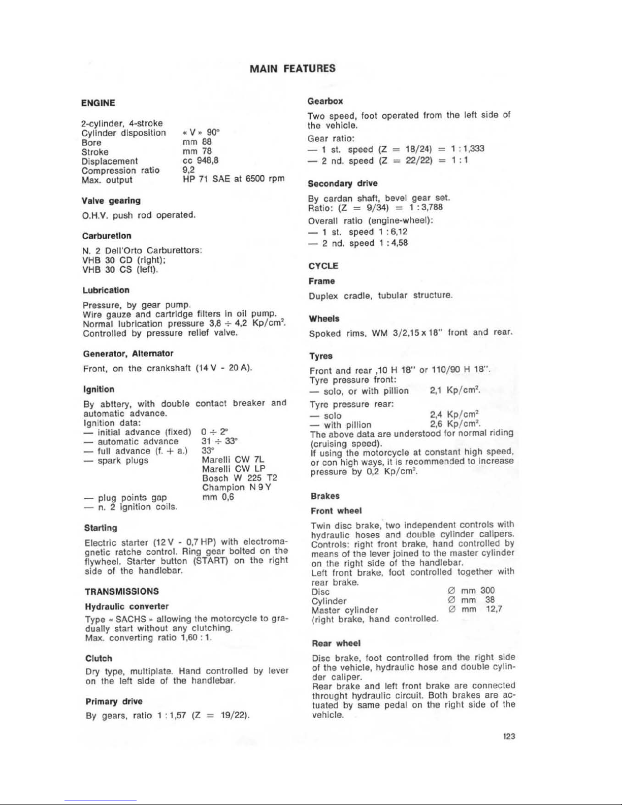
FEATURES
ENGINE
2-cylinder, 4-stroke
Cylinder disposition
Bore
Stroke
Displacement
Compression r
alio
Max. output
.. v ..
90"
mm
88
mm 78
cc 948,8
9,2
HP
71
SAE at 6500 rpm
Valve gearing
D.H.V. push rod operated.
Carburetlon
N. 2
Dell'Orto Carburetl ors:
VH
B 30
CD
(right):
VHB 30
CS
(left).
Lubrication
Pressure, by gear pump.
Wi
re gauze and cartridge filters In oil pum
p.
Nor
mal lub ricatio n pressure 3,8
-:-4,2 Kp/ cm'.
Controlled
by pressure relief valve.
Generator, Alternator
Front, on the crankshaft
Ignition
By abllery, with double
automatic advance.
Ignition data:
- initial advance (fixed)
- automatic advance
-
full advance (f. + a.)
- spark plugs
- plug points gap
- n.
2
ignition
coils
.
Starting
114
V - 20 A).
contact breaker and
0
-:-
2"
31
+
~
33"
Marelli CW 7L
Maralli CW LP
Bosch W 225
T2
Champion N 9 Y
mm
0,6
Electric starter (12 V - 0,7 HP) with electroma-
gnetic
ratche control. Ring gear bolted on the
flywheel. Starter button (START) on the right
side
01
the handlebar.
TRANSMISSIONS
Hydraulic
converter
Type .
SACHS " allowing the motorcycle to gradually
start
without
any clutching .
Max. converting ratio 1,
60
: 1.
Clutch
Dry type,
multi plate. Hand controlled by lever
on the left side of the handlebar.
Primary drive
By
gears, rat;o
"',57
IZ
= 19/22).
Gearbox
Tw
o speed,
loo
t operated from the left side of
the vehicle .
Gear ratio:
- 1 st. speed
(Z = 18/ 24) = 1 : 1,333
- 2 nd. speed
(Z
= 22/22) =
1:
1
Secondary drive
By cardan shaft, bevel gear set.
Ratio :
(Z
= 9/34) = 1 : 3
,7
88
Overall ratio (engine-wheel):
- 1 st. speed 1 : 6,12
- 2 nd . speed 1 : 4,58
CYCLE
Frame
Duplex cradle, tubular structure.
Wheels
Spoked
rims,
WM
3/ 2,15 x 18"
hont
and rear.
Tyres
Front and rear ,10 H 18" or 110/90 H 1S".
Tyre pressure front:
_ solo,
or
with pillion 2,1 Kp/ cm
2
•
Tyre pressure rear:
_ solo
2,4
Kp/cm
2
_ with plilion 2,6 Kp/cm
2
•
The above data are understood for normal riding
(cruising speed).
If using the motorcycle at constant high speed,
or
can
high
ways,
it
is recommended to increase
pressure by
0,2 Kp /
cm
2
•
Brakes
Front wheel
Twin disc brake, two independent controls with
hydr
aulic hoses and double cyl inder calipers.
Controls : right front brake, hand controlled by
means
01
Ihe lever joined to the master cylinder
on the right side
of
the handl ebar.
Left front brake, fool controlled together with
rear brake .
Disc
Cylinder
Master cylinder
(right brake , hand controlled .
Rear wheel
o
mm
300
(2)
mm 38
o mm 12,7
Disc brake , foot controlled from the ri
ght
side
of the vehicle, hydraulic hose and double
cylin-
der
caliper.
Rear brake and left front brake are connected
throught hydraulic circuit. Both brakes are
actuated by same pedal on the right side of the
vehicle.
123

Disc
Cylinder
Master cylinder
Parking brake
o
mm
242
o mm 38
o mm 1
5,875
Mechanical brake, acting on the hydraulic rear
wheel brake. The load given by a parked vehicle
on its side stand comes to bloc k up the rear
braking disc through a lever trasmission system.
Dimensions and wei
ght
s
Wheelbase
M
ax.
length
FU
EL
AND OIL CAPACITIES
CROUP OR
PART
Fuel tank
Aeserve (warned
by light)
Engine oil sump
Gear oox
m 1,470
m 2,200
o
TIES
"
2.
•
3
Max.
widt
h
Max. height
Min. ground clearance
Curb weight
(without accessories)
PERFORMANCES
Max. speed, solo riding:
Low
Drive
Fuel consumption
m 0,
650
m 1,
tOO
m 0,
150
Kg
261
approx.
Km
/h
130
Km
/h
174
Jt6x100Km
A(COMMENO£D
TYPES
l
Petrol 98/
100
NO·AM
Oil Agip Sint
2000
SAE
10 W/SO
0,600
Oil
Agip
F.1 Aotra
MP
SAE
90
Converter c:rcuit
1,5
.;.-
1,7
Agip
F. 1 ATF Cexron
(filting q.ty after eventual overhauling)
Rear drive
box
0,230
Oil
Agip F.1 Rotra
MP
SAE
90
0,020 Oil
..
Molykote . type
..
A •
Fronl fork (each leg)
0,070
Agip
F. 1 ATF Cexron
Braking circuits
Fluid Aglp F. 1 Brake Fluid
SAE J 1703
124
tl
FIG
N
REF
.
58
18912450
59
18911650
60
18927650
61
16913850
62 1
890
69
50
63
18929150
64
18928
950
65
18927150
66
It\92
72
50
67
10927350
68
18926500
69
18926600
70
1
8926
7 00
71
12912700
72
14926900
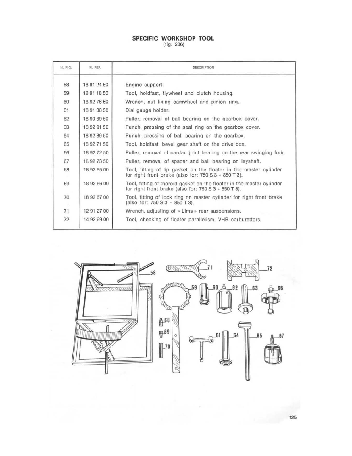
SPECIFIC WORKSHOP TOOL
(fig.
236)
O£SCIIIPTION
Engi
ne
support.
Tool, holdlasl, flywh eel and clutch hous ing.
Wrench, nut fixing camwheel and pinion ring.
Dial gauge holder.
Puller, removal
01
ball bearing on the gea
rb
ox cover.
Pun
ch, pressing 01 the seal ring on the gearbox cover.
Punch, pressing of ball bearing on the gearbox.
Tool. holdfasl, bevel gear shaft on the drive box.
Pu
iter, removal of card
an
joint beari
ng
on the rear swinging fork.
Pulter, removal 01 spacer and ball bearing on layshaft.
Tool, f
illing
01
lip gasket on the floater in the master cylinde r
lor r
ight
front brake
(also
for : 750 S 3 - 850 T 3).
Tool, fitting of thoroid gasket on the floater
in
the master cylinder
for right front brake (also for: 750
S 3 • 850 T 3
).
Tool,
filling
of
lock
ring on master
cylinder
for r
ight
front brake
(also for:
750
S 3 • 850 T
3).
Wrench , adjusting of • Lims
.. rear
suspensions.
Tool, checking of fl
oa
ter parallelism, VHB carburettors.
. . I
T
il
.
o
125
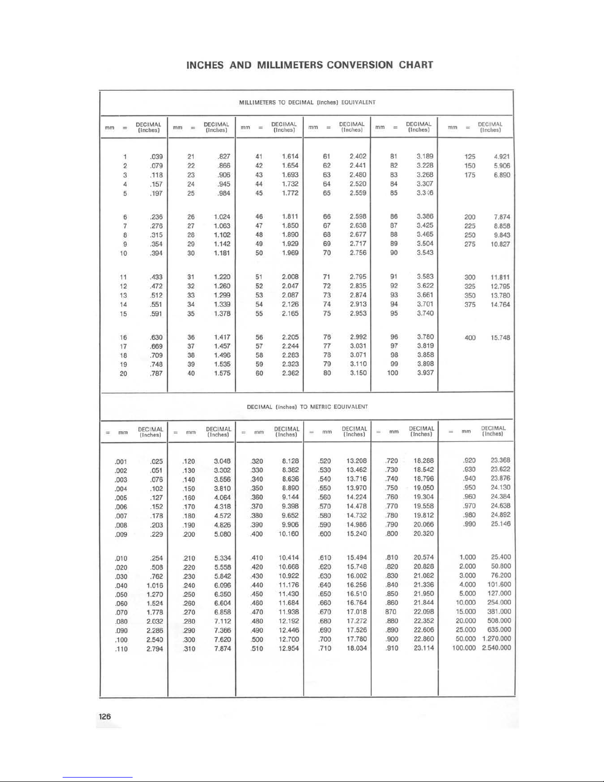
INCHES AND MILLIMETERS CONVERSION CHART
MIUIMET'ERS
TO
DECIMAL
(1nd'.~1
EOUIVALENT
~
-
DECIMAl
(Inc",".)
~
-
DECIMAL
~
-
DECIMAL
Onc:tw
o)
,'flCh
u]
~
-
DECIMAL
0",,""')
mm
-
DECIMAL
-
-
DECIMAL
[lncl>o
.)
"nc""')
,
.039
"
.821
"
1.
614
"
2.402
"
3.189
"5
4.921
2
.07
9
22
.
...
42 1.654
62
2.441
82
3.226
'50
5.006
3
.118 23 .906
"
1
.693
63
2.480
"
3.268
"5
6.890
•
.157
"
.
"5
..
1.732
"
2.520
..
3.307
5 .197
25
.
...
'5
1.772
65
2.559
85
3.3~6
6 .236 26
1.024
"
1.811
66 2.596 86
3.386
200
7.874
7 .276
27
>.063
"
..,50
67
2.638 87 3.425
225 8.858
8
. 315 28
1.102
..
>.
...
..
>677 88 3.465
250
'.8<3
9
'"
29
1.142
"
1.929 69
2.111
89
3.5<>1
275
10
.827
"
.394
30
1.181
50
>.'"
70
2.756 90 3.
543
"
.433
"
>.'"
"
2.008
"
2.195
"
3.583
300
11.811
"
.472
32
>.260
52
2.047
12
2.835
92
3.622
325
12.795
"
.512 33
>.",
53
2.
081
73
2.874
93
3.
661
350
13.780
"
.551
3<
'
.339
"
2.
126
"
2.913
"
3.701
375
14
.764
"
.591 35
1.378
55
2.
165
75
2.953
95
3.740
"
.830 38
1
.'111
56
2.205
76
2.992 96
3.
780
"Xl
15.748
"
.
669
37
1.451
"
2.244
77
3.031 97 3.819
"
.709 38
1.496
"
2.283
78
3.071
98
3.858
"
.
748
39
>.".
"
2.323
79
3.110
99
3.896
20
.7
87
<0
1.575
60
2.362 80
3.
150
'"
3.937
DECIMA.l. {Inc
..... ) TO
METRIC EQUIVALENT
~
[)[CIMAL
-
Clnch
••
1
-
mm
D£CIMAL
-
mm
DECIMAL
(Inche_) (Inch
••
)
-
mm
DECIMAL
(lnche.)
-
mm
DECIMAL
(lnche.)
-
~
[)[CIMAL
(Inc"")
.00'
.025
.
'20
3.048
.320
8.128 520 13.208 .720
18.
288
.920
23
.388
.002
.
05'
'30
3302
.330
8.382
530
13.462 .730
18.
542
.930
23.622
.003
.0
78
.
''''
3.556
.3<'
8.636
'"
13.
716
.740
18
.796
.
9<,
23.
876
.00'
.102
.
'50
3.810
.350
8.890
.550
13.970
.
7SO
19.050 .950
24.130
.005
.127
.'60
'
.064
.360
9.144
560
14.224 .760
19.304 .960
24.384
.006 .152 .170
4.
318
.370
9.398
.570 14.478 .770
19.
558
.
970
24.638
.007
.178
.'
80
4.572
.380
9.652
580
14.732
.780
19
.812
.980
24.892
.008 .203
.
'"
'826
.390
9906
.590
14.986 .790 20.066
.990
25.146
.009
229
.200
5.080 '<00
10.160 .600
15.240
.800
20.320
.
010
.
2"
.
210
5
.33<
.
410
10.414
.610
15.494 .
810
20
.574
>.()OO
25.
400
.020 .508
.220
5.558
.""
10.668
.620
15.748
.820
20.828 2.000
SO.800
.030
.762
230
5.842
'<30
10.922
.630
16
.002 .830
21.082
3.000
76.200
.0<0
1.
016
2<0
6.096
.
'"
11.176
.""
16.256
.
'"
21.336
'.000
101.600
.060
1.
270
2SO
6.350 '<50
11.
430
650
16
.510 .960 21.950 5.000
127.000
.060
1.524
.
260
6.60<
.
'"
11
.684
.660
16.764 .860
21
.844 10.000 254.000
.070
1.
778 .270
6.658 .470
11.938
.
670
17.016
87'
22.096
15
.000 361 .000
.080
2.032
280
7.112
.'80
12.192
.680 17.
272
.980
22.352 20.000 508.000
.090
2.266
.290
7.388
.<90
12.446
.690
17.526
.890
22.606 25.000 635.000
.'00
2.
540
.300
7.620
.500
12.700
.700 17.760 .900 22.660
SO.OOO
1.
270
.000
.110
2.794 .
310
7.874 .510 1
2.954
.
710
16.034 .910
23.114
100
.000 2.540.000
".
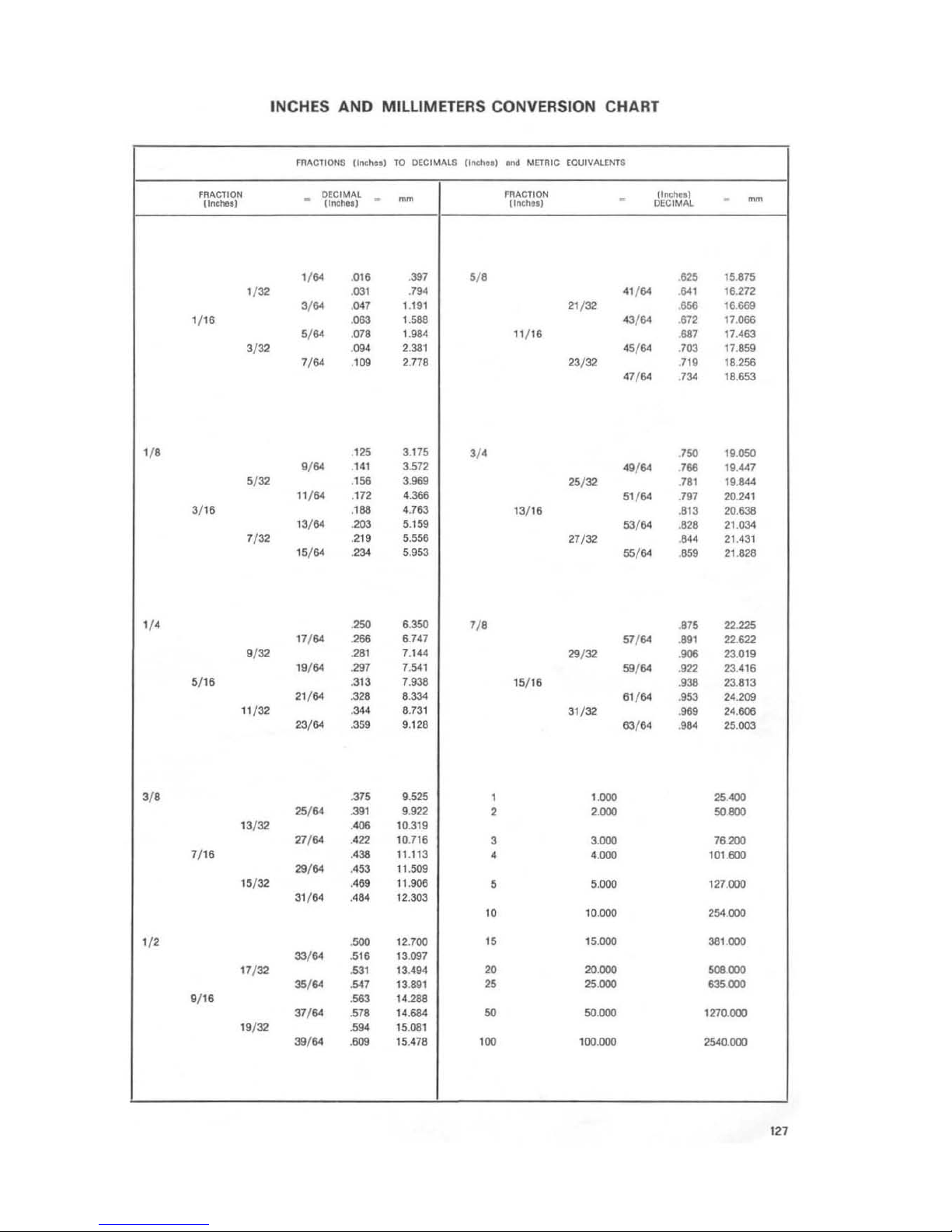
INCHES AND MILLIMETERS CONVERSION CHART
fRACTIONS
II!lCtto.)
TO
DECIMALS (Inctto.)
lrocI
MElRIC
EOUIVALfN1$
FRACTION
.
DECIMAL
.
~
FRACTION
.
II
I'II;httl
.
~
Unchftl
(lnchHl
(Inch • • )
DECIMAL
'/"
.
016
.397
5/ '
."
15
.815
'/"-
.
03'
.
,..
41/64
'"
16.272
3/ "
.047 1.
191
21
/ 32 .656
16.669
t/16
.063
'
.588
43/
64
67'
17
.066
5/ "
.078
L984
11
/ 16
"7
17.463
3/32
.
094
2.381
45/
64
.703
17.859
7/"
.'"
2.778 23/32 .
1\9
18
.256
47/ 64 .
73<
18.
653
'I'
.."
3.175
3/ '
7SO
19
.050
./"
.
141
3.
572
49/
64
766 19.447
5/ 32
.'"
3.969
25/"-
.
781
19
.844
11
/64 .172
'.
396
51
/64
.791
20
.241
3/
16
.'"
4.763
13/16 .813 20.638
13/64
.203 5.159
53/"
.
82'
21
.034
7
/"
.2
19
5.556
27/32
.
".
21.431
15/
64
".
5.953
55/"
.859
21
.828
'I'
.250
'
.350
7/ '
.875 22.225
17
/64
.266 6.741
51/
84
.
89'
22.622
9
/32
.
28'
1.144
>9",
.006
23.019
19/64
>97
7.541
59/"
.922 23.416
5/
16
.313 7.938
15/16
.938
23.813
21/64
.".
'
.33<
61
/64 .853
24.209
11
/32
.
3<'
8.731
31/32
.969
24
.606
23/&4
.359 9.128
63/64
.984
25.003
3/ '
,,,
9.525
,
LOOO
25 ....
25/84
.39'
9.922
,
'.000
SO
800
13
/ 32 .406
10.319
,,
/
..
.422 10.716
3 3.000 78.200
1/16
.438
11.11
3
•
' .000
101
.600
>9
/"
.453 11.509
15
/ 32 .469
11
.906
5 5.000
127
.000
31/64
..
"
12
.303
"
10
.000
254
.000
'I'
.500
12.700
"
15.000
381.000
33/"
."
13.097
17
/32
.."
13.494 20
20.000
508.000
,./"
.547 13.
891
25 25.000 635.000
9/16
.563 14.288
37/ 64 .578
14.684
SO
SO
.
OOO
1270.000
19
/32
.'"
15
.081
39/"
.609 15.478
'"
100.000
2540.
000
127
DISMANTLING, INSPECTION
AND
RE-FITIING OF VEHICLE
PARTS
Removal
01
the engine unit from the frame:
-
se
l the vehicle on the center stand;
- loosen the screws and remove the windshield group together with connections;
- loosen the screws and remove side bags,
side bag housings and rear safety bar;
- lift the saddle, using its proper rod;
- detach the wiring from the level
indicator
and electro-valve;
- by means
of
pliers spread the retaining
springs, then remove the pipes from the
fuel
lap
and electro-valve;
- unhook
.the clamp securing the luel
lank
(rear side) and slide
oul
the
lank
from the
bushings
on
the frame (front side);
- loosen the screws securing exhaust pipes
to cylinder heads;
- loosen the screws
on
the clamps securing
exhaust pipes and silencers to expansion
chamber;
- loosen the screws securing silencers to
frame; then remove exhaust pipes and sIlencers;
- remove the battery covers;
- unhook the bracket and remove the tool box;
- detach the electric
wi
ring, unhook the se-
curing
clamps and remove the battery;
-
loosen the filler screw from the converter
reservoir and drain the
liquid from the re-
servoir
itself;
-
loosen the screw securing drain pipe
to
converter cover, then drain the liquid;
- undo the blind nut securing the recovery
pipe, remove the pipe from the holder on
the converter cover and drain the
liquid
from the converter radiator;
- detach the parking brake control
cable from
the lever on the caliper;
-
loosen the screws and remove: mechanical
and hydraulic caliper from the holder, paying
attention to the quantity of shims between
the
calipers and the
caliper
holder, then
fix the hydraulic caliper to the frame;
- loosen the
wheel spindle nut on the drive
box side and the screw securing the pin
itself to the swing
arm; then slide out the
wheel spindle from drive box, wheel hub
and rear swing arm;
-
slide out the caliper holder together with
its spacer, paying attention to the position
' 28
of the spacer itself (the lowered side must
face the
whee l hub);
- slide out the gear
on
the wheel hub from
the
drilled pin on the drive box, shifting the
wheel towards the left side of Ihe swing arm:
-
lean the vehicle to the right and remove Ihe
wheel
from the drive box and the rear swing
arm;
- undo the nuts securing the
re
ar suspension
to
the drive box and swing arm;
- loosen the screws on the clamps securing
the gaiter covering
Ihe cardan joint;
-
loosen the nuts on the pivot screws, then
the screws securing the swing arm to frame
and remove the rear
Swing arm complete
with drive box and u-Jolnt from the
layshail
in the gearbox;
- set the
block
n. 1891 2450 (58 in fig .
237)
under the engine
unit
and screw in the
three screws in such a way
as
to lift the
engine unit off the ground;
- detach the wires from spark
plugs and slarter motor; then take off the alternato r cover
and detach the electric wiring from
alterna-
lor
, parking brake cutout, coils, oil pressure
cutout;
loosen
the screws securing Ihe front fender
(rear side) and the nuts on the engine
moun-
ting bolts;
- detach the speedometer cable from the gearbox housing;
- remove the
circllp
and connecting pin
on
the control lever for the integrated braking
system, Remove the cotter pin and fixing
pin on the gearbox lever;
- remove the engine mounting
balis, then
take
all
the frame cradle arms complete
with center and side stands;
- loosen
the securing screws and remove the
starter motor from the converter cover;
-
lift the frame unit, then take off the engine-
gearbox unit from the frame (see fig.
238)
.
An assistant
will
be
needed for this operation,
To separate the engine-converter unit from the
Clutch-gearbox ass.y proceed as follows:
- the engine-gearbox
unit
has to be placed
on the support
block
In such a way that the
gearbox side is upwards, to prevent the
converter oil from draining oul; then loosen the
securing nuts and separate the gearbox
ass.y from the engine unit (see fig. 239).

STRIPPING
THE
ENGINE
UNIT
- drain the converter oil with a syringe (see
fig.
240);
- flatten the wings
01
the secu ring plates ,
then loosen the retaining screws and
re·
move the converte r and the starter ring
gear (see fig.
240/1);
- remove the
cylinder
head covers, then bring
the pistons
to
T.D.C. (closed valves) and
slide
out
the rocker;
- remove the rocker·push rods assembly, then
loosen the nuts and remove rocker holders
and
cylinder heads;
- remove the alternator from the crankshaft,
using the
proper
Allen key and pin 14906600;
-
lake
all
the gaskets between cylinders and
cylinder heads, then remove the cylinders
and
lake
off the gaskets between cylinders
and crankcase;
- using pliers
lake
off the piston pin circlips,
then using the special tool
26907800 (11
in lig.
17)
slide out the piston pins.
Caution: when removing
cylinder head, piston and cylinder ass.ies, pay allention to
take left and right ass.y
well apart;
- flaUen the wings of the securing plates, fit
the special tool
18911850
(59
in fig. 241)
on
the flywheel and remove the flywh eel:
toos
en
the screws and remove the valve
gearing cover;
th
is cover fits the converter
leed pump, which is controlled by the
camshaft and the valve controlling the pressure
of the converter hyd r
au
lic
circuit;
- loosen the nut securing the oil pump gear,
using eye wrench and holdfast tool n.
14927300:
- loosen the nut securing the camwheel using
the tool
14927300
(20
In
fig.
242)
and
special wrench
18927650
(60 in fig. 242):
- flatten the washer securing wings and take
out the ring using tool
14927300
(20
in
fig. 243) and special wrench 14
92
76
00
(60
In fig. 243);
remove the valve gear and chain ass.y from
the shafts;
- loosen the screws and remove the camshaft
securing flange and the camshaft from the
holders on the crankcase;
- loosen the screws and remove the oil sump
from the crankcase. The oil sump
will be
complete with
filters and oil pressure relief
valve:
- loosen the nuts and dismantle the con-rod
caps, then remove the can rods through the
cylinder holes in the crankcase:
- flatten the wings
01
securing plates, remove
piping and securing screws then remove
the flange, from the crankshaft, lIywheel
side, using the tool
12913600
(18 in fig. 19):
- dismantle the crankshaft from the flange,
valve gearing side;
- flatten the wings of the securing plates,
loosen the screws and remove the flange,
valve gearing side:
- dismantle the cylindre head, using
1001
1090
72
00
(12 in fig. 16) and proceed as
follows;
- set the tool on the upper plate and
valve:
- screw in the tool screw
10
tighten the tool
Itself: in order
to
avoid any tool distortion,
tap on the tool head, if a strong resistance
in screwing is found: this bealing
will make
the two semlcones free from the upper plate:
- screw in to remove the two semlcones from
the upper plate;
- take out the
tOOl,
then remove upper plate,
ouler spring, inner spring bottom plate, shims
and finally the valve.
'2.

CHANGES
FOR
ENGINE OVERHAULING·
ROCKER
COVERS · CYLINDER HEADS
•
VALVES·
SPRINGS
RE
·FITTING
OF
HEADS
ON
CYLINDERS
Pay attention that the cylinder lubrication hole
(arr
ow
..
A ») is aligned with both the gasket
lubrication hole (arrow
.. B ..
) and the head
lubrication hole
(arrow"
C
>0),
fig.
244.
130
In
order
not to damage
the
cylinder
head when
locking the nuls, it is necessary to follow a
crossed sequence
(1
- 2 - 3 - 4 - 5 - 6 - fig.
29)
and torque to 4
-+-
4,5 Kgm (approx.
20
pounds).
Remember to always replace the gasket belween cylinder and head.
CYLINDERS · PISTONS · PISTON RINGS
CYLINDERS
Cylinder
weari ng
The cylinder bore should be measured at 3
different heights, turning the dial gauge
90".
The dial gauge has to be previously set to zero
on the
slip
ring (see fig . 245 and Drwg . 246)
also make sure that cylinder and piston are
matched
(A
with
A,
or B with - see the
arrow
and fig.
248).
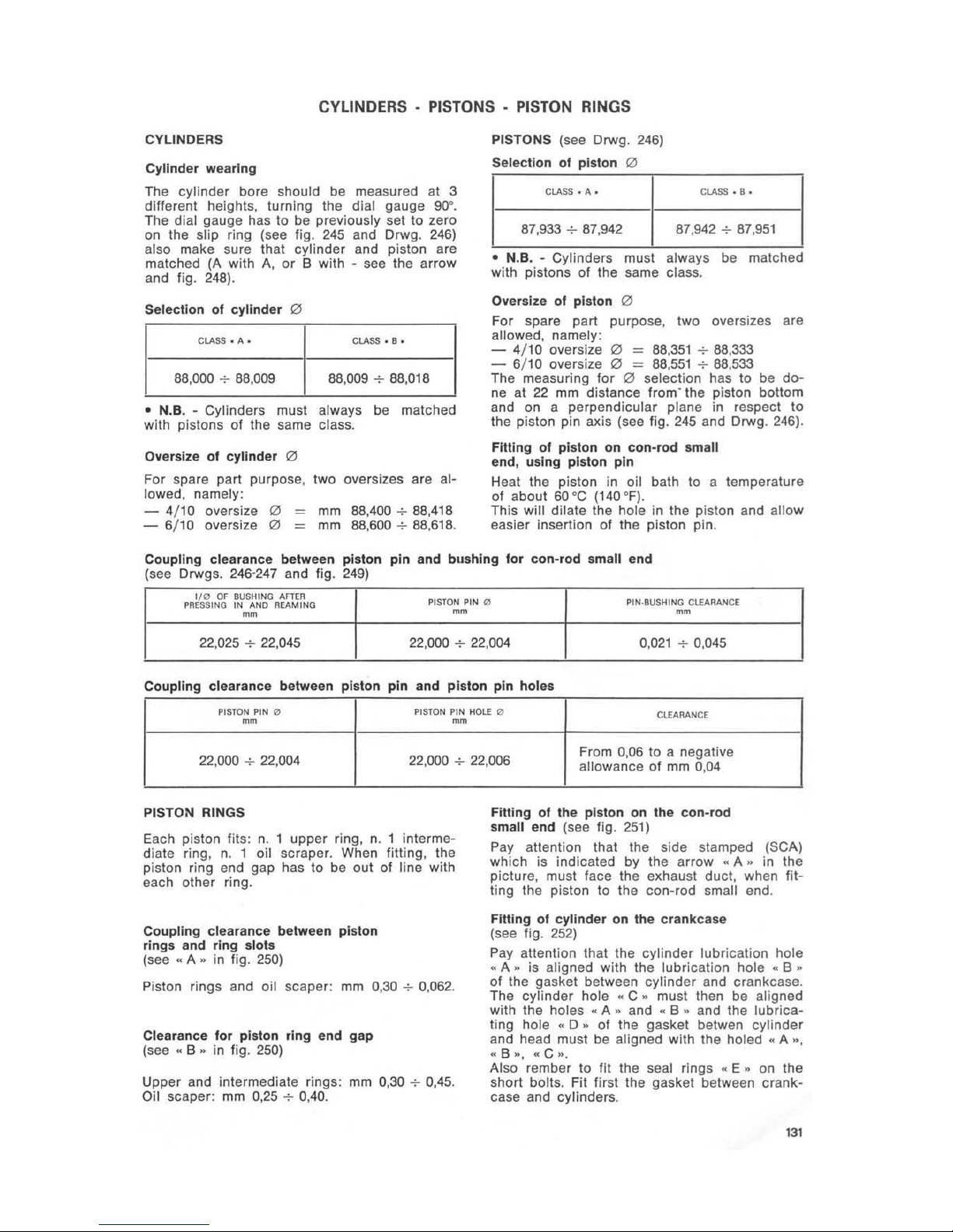
Selecllon of
cylinder
(2)
CLASS . A • CLASS • 8 •
88,000 + 88.0
09 88,009 + 88,018
•
N.B. - Cylinders must always be matched
with pistons of the same class.
Oversize
of
cylinder
(2)
For
spare part purpose, two oversizes are al-
lowed. namely:
- 4/10 oversize
(2)
= mm 88,400 + 88,418
- 6/10 ove rsize
QI
=
mm 88,600 + 88,618.
PISTONS (see Drwg . 246)
Selection of piston
QI
CLASS • A • CLASS • B •
87,933 + 87,942 87,942 +
87,951
• N.B. - Cylmders must always be matched
with pistons of the same class.
Oversize
of pis
ton
(2)
F
or
spare part purpose, two oversizes are
allowed, namely:
-
4/
10
oversi
ze
(2)
=
88
,351
+ 88,333
-
6/10
oversize
(2)
= 88
,551
+ 88,533
Th
e measuring for
(2)
selection has to be
do-
ne at
22
mm distance Irom' the piston bottom
and on a perpendicular plane
in
respect to
the piston pin axis (see fig.
245
and Drwg. 246).
Fitting of piston on con-rod small
end, using piston
pin
Heat the piston in oil bath to a temperature
01
about 6O"C (140 OF).
This will dilate the hole in the piston and allow
easier insertion
01 the piston pin .
Coupling clearance between piston pin and bushing for con-rod small end
(see Drwgs. 246'2
47
and lig.
249)
g0
OF
BUSHING
AflEJI
PR
SSING
IN
AND
REAMING
PISTON
PIN
0
PII4·BUSHING ClEAJlANGE
~
mm mm
22,025 + 22,045 22,000 + 22,004 0
,021 ..;.
0,045
Coupling
clearance between piston pin and
piston
pin holes
PISTON
PIN
0
PISTON
PIN
HOLE
0
ClEAJlANCE
mm
~
22,000 + 22,004 22,000 + 22,006
From 0,06 to a negative
allowance of mm
0,04
PISTON RINGS
Each piston fils: n. 1 upper ring, n. 1 intermediate ring, n. 1 oil scraper. When fitting, the
piston ring end gap has to be o
ut
of line with
each other ring.
Coupling clearance between piston
rings and rIng slols
(see"
A »
in
fig. 250)
Piston rings and oil scaper: mm
0,30 + 0,062.
Clearance for pIston ring end
gap
(see
.. B ..
in fig.
250)
Upper and interme diate rings:
mm
0.30 + 0,45.
Oil
scaper: mm 0,25
..;.
0,40.
Fitting of the piston on the con-rod
small end (see fig.
251)
Pay allention that the side stamped
(Se
A)
which is indicated by the arrow
"A
..
in the
pictu re. must face the exhaust duct. when
fit-
ting the piston to the con-rod small end.
Fltllng of cylinder on the crankcase
(see fig.
252)
Pay allention that the
cylinder
lubrication hole
" A
..
is aligned with the lubrication hole
.. B ..
01
the gasket between
cylinder
and crankcase.
The
cylinder
hole
.. C ..
must then be aligned
with the ho les
.. A ..
and
"B
..
and the lubrica-
ting hole
.. 0 ..
01 the gasket betwen cylinder
and head must be aligned with the
holed" A ",
.. B .. , "C
».
Also rember
to
fit the seal rings
"E
..
on
the
short
bolls. Fit first the gasket between crank-
case and cylinders.
131
CON.RODS .
CRANKSHAFT·
MAIN
BEARINGS. FLYWHEEL AND VALVE
GEARING SIDES
Selection for crankshaft and con-rod
Th
e con-rods
.. A ..
- while marked - must be
matched with the crankshaft
..
B » - white mar-
ked -; while the con-rods
..
A,.
blue marked
must be matched with the crankshaft
.. B ..
-
blue marked.
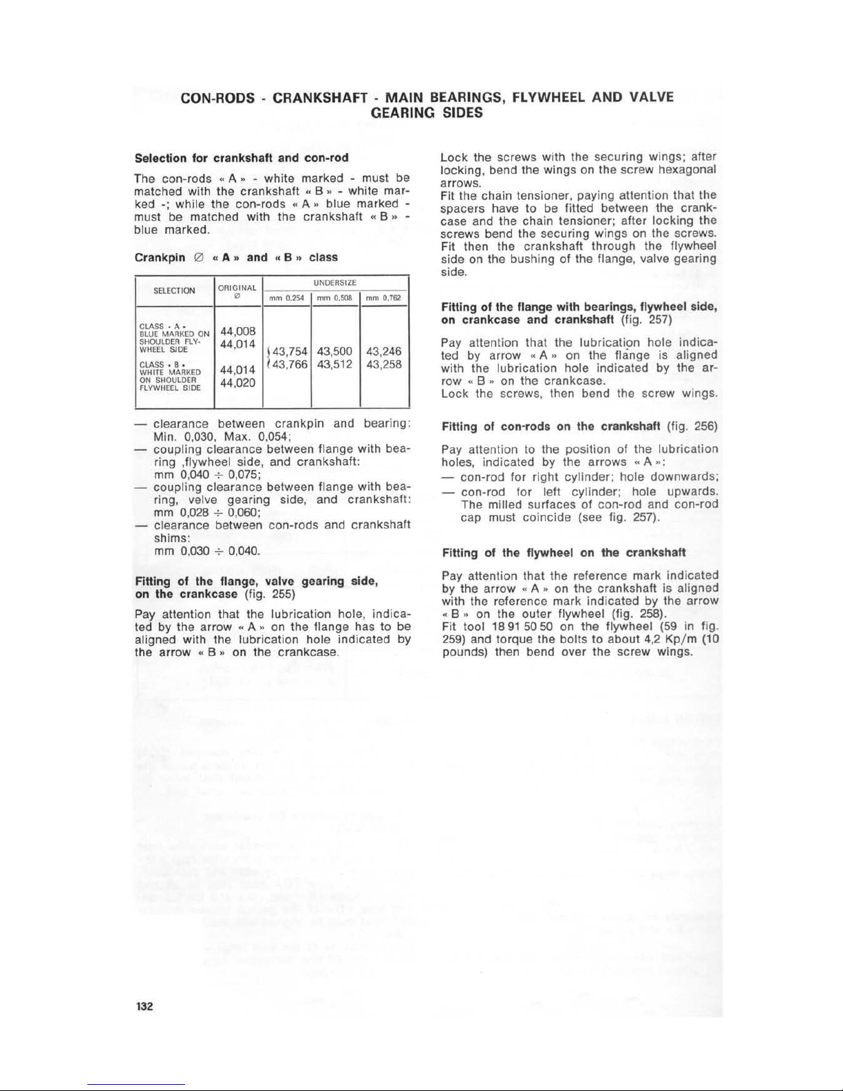
Crankpin 0 " A
..
and
..
B » class
ORIGINAL
UNDERSIZE
SElECTI
ON
0
mtn
1I.:B4
mm
O,5O!I
mm 0.162
CLASS · A .
44,008
BLUE MARKED
ON
SHOULD
ER
FLV·
44,014
WHEEl SlOE
t 43,754
43
,500 43,246
ClASS . 8 .
44,014
43.766
43
,512
43,258
WHITE
MARKED
ON
SHOULDE
R
44,020
FLYWHEEL
SlOE
- clearance between crankpin and bearing:
Min. 0
,030,
Max. 0,054:
- coupling clearance between flange with bea-
ring ,flywheel side , and crankshaft:
mm 0,040
-:-
0,075;
- coupling clearance between flange with bearing, velve gearing side, and crankshaft:
mm
0,028 + 0,060;
- clearance between con-rods and crankshaft
sh
ims:
mm
0,
030
-;-
0,040.
Fitting of the flange, valve gearing side,
on the crankcase (fig.
255)
Pay attention that the lubrication hole, indicated by the arr
ow
..
A " on the flange has to be
aligned with the lubrication hole indicated by
the arrow
" B " on th e crankcase.
132
L
ock
the screws with the securing wings; after
lock
ing, bend the wings on the screw hexagonal
arrows.
Fit the chain tensioner, paying attention that the
spacers have to be fitted between the
crank-
case and the chain tensioner; after locking the
screws bend the securing wings on the screws .
Fit then the crankshaft through the flywheel
side on the bushing of the fl ange, valve gearing
side.
Fitting
of
the flange with bearings , flywheel Side,
on crankcase and crankshaft (fi
g.
257)
Pay attention that the lubrication hole
indica-
ted by arrow " A " on the flange
is
aligned
with the
lubricat
ion hole indicated by the ar-
row « B
..
on the crankcase.
lock
the screws, then bend the screw wings.
Fitting of
co
n-rods
on
the crankshaft (fig. 256)
Pay attention to the position
01
the lubrication
holes, indicated by the arrows
..
A
":
- con-rod for right cylinder; hole downwards;
- con-rod for left cylinder; hole upwards.
Th
e milled surfaces
01
con-rod and con-rod
cap must
coincide
(see fig. 257).
Fitting
of
the t1ywheel on the crankshaft
Pay attention that the reference mark indicated
by the arrow
..
A " on the crankshaft is aligned
with the reference mark indicated by the arrow
.. B ..
on the outer flywheel (fig.
258)
.
Fit tool
18915050
on the flywheel
(59
in fig.
259)
and torque the bolts
to
about 4,2 Kp/ m (10
pounds) then bend over the screw wings.

VALVE
GEARING
TIMING DATA (fig.
260)
Referred to the clearance of 0
,5
mm
between
rocker a
nd val
ve.
Inlet :
- opens
20"
before T.D.C.
-
closes 52" after B.
D.C
.
Exhaust:
- opens
52" before S.O.C.
- closes
20"
after T.D.
C.
Working clearance between (ocker and valve,
cold engine,
mm
0,22.
o
of
camshaft holders and
holder
seats on
the
crankcase
:
o
CAMSHAFT
HOlDE" o
HOLDE"
$EAT
COUPlINO
CI.EARAHC£
~
~
-
47,000 47,025
Valve gearing side
46
,984 47,050
0,025
-:-0,066
32,000 32,025
Flywhe
el
side
31,984 32,050
Coupling data
for
tappets and tappet seat
on
the crankcase:
o
TAPI'£T
SEAT
-
Original 0 22,021
-:-
22,000
)
0,05 22,071
-:-
22,050
Oversize 0
0,10 22,
121
-:-
22,100
FITTING
OF
CAMSHAFT AND GEARING
WITH
CHAIN
After lilting the oil pump and the chain tensioner ass.y proceed
as
follow
s:
-
lit
the camshaft
«A
..
in fig.
261
onto the
seats in the crankcase and secure the shaft
to the crankcase. using
lIange
..
B " in fig.
261
and screws with toot her washers
..
C "
In
fig.
261;
-
iii
the gear ass.y with chain
..
0 " in fig .
261
on the gears
01
camshaft, crankshaft, and
oil pump shaft (this group has already been
mounted previously) paying allention to the
alignment of the reference marks
..
E"
in
fig .
261
on the gears (camwheel and engine
pinion) thus indicating the valve operation
Is
correctly timed; then fit the stop pin
..
F "
In
fig.
261
into the camshaft hole
.. H ..
in
fig. 261; also pay allention to the key seal
on the engine pinion
..
I " in fig.
261
;
-
lock
the nut with spring washer
«M"
lig
.
261
securing the camwheel on the camshaft
using to
ol
n. 1
4927300
(20
In
fig.
262)
and
special wrench
18927650
(60
in fig.
262)
;
o
OU
TER
TAPI'£T
COUPlING
CI.£ARANCE
-
-
21,996
-:-
21,978
0,004
-:-0,043
22,046
..;.-
22,028
22,096 + 22,018
-
lock
Ihe ring wilh washer
..
M " fi
g.
261
securing the engine pinion on Ihe crankshaft ,using
tool
14927300
(20
In fig.
263)
and special wrench
14927600
(60
in fig.
263); flatten one washer wing inlo a ring
hollow;
- lock the nul with washer
..
N " lig.
261
se-
curing the control gear on the
oil pump
shaft, usi
ng
1001
14927300
and special eye
wrench, remember to set the key
..
0 "
fig .
261
onto the shaft 1lself.
After this
fitting. check again the alignment
01
th
e two reference marks on the gears (cam-
wheel and engine pinion)
..
A " fig.
264,
then
Iii tappets
«a"
into the seats
..
P " on the
crankcase (see fig.
261).
CHECKING THE VALVE TIMING WITH
ENGINE ON
VEHICLE
- Remove the spark plugs from the cylinder
heads;
-
loosen t
he
screws and remove the rocker
covers;
133
- set clearance between rocker and valve
to
mm
1,5;
-
loosen the screws and take off the flywheel
cover;
- remove the rubber cap fr
om
the inspection
hole on the right side of the converter cover;
- using a
proper
tool, rotate the alternator
until the right hand piston is at T.D.C. (clo-
sed valves); looking through the inspection
hole, the letter
..
0"
must be seen at the
middle
01
the mark
on
the hole rim;
- fit the
tool with arrow
12927500
(26 in
fig.
265)
onto the valve gearing cover and
lock it by means of the screw;
- loosen the sc rew securing
alternator to
crankshaft an d
!itthe
degree wheel 14927400
25
in fig . 265) on the alternator itself; after
pointing the mark
P.M.S. (T.O.C.) with the
point of the checking tool, secure the disc-
1
34
alternator
group
to the crankcase by means
of the
alternator screw;
looking through the inspection hole, ensure
thai the
leiter
..
0"
of the wheel is still
at
the middle of the mark
on
the hole rim;
rotate the
alternator with the degree wheel
1280 clockwise. starting from the
P.M
.S.
(T.o.C.) mark which is aligned with the point
of the checking
tool.
At this tage, under normal conditions, the
exhaust
valve of the right cylinder must starl
opening. After checking everything is
normal,
re-set the rocker-valve clearance to 0
,22
mm
then
fit rocker covers and rubber cap
on
the
inspection hole; remove the checking
tool from
the valve gearing cover and the degree
wheel
from the alternator. Lock the alternator securing screw and re-fit the alternator cover
on
the valve gearing cover. Ae-fit the spark plugs
onto the cylinder heads.
ENGINE LUBRICATION
DESCRIPTION
This type of engine fits an all filter which, in
addition to a wire gauze, filler
.. 0 ..
is also
provided with a filter cartridge
.. A ..
fig.
266
This ensures an almost Integral filtering before
the oil passes in ttle pump and lubricating
channels.
OIL
SUMP (fig. 266)
The
oil
sump
.. C ..
fils:
..
A"
filter cartridge, replaceable;
..
B "
magnetic
all drain plug;
.. 0 ..
wire gauze filter;
"
E
..
oil pressure reliel valve.
FILTER CARTRIDGE, REPLACEABLE (fig. 266)
The filter cartridge
.. A ..
has to be replaced
every 15.000 Km (9,000 mile
s)
(five oil changes)
by proceeding as follows:
- undo the drain plug «B " with aluminium
washer as
well
8S
the plug
.. F..
with alu-
minium washer on the crankcase and lei
the oil drain into a basin, which has been
previously set under the sump
..
C
..
;
- loosen the screws securing the sump to the
crankcase and remove the complete sump
.. C ..
;
- take off the cartridge
..
A.
the wire gauze
.. 0 ..
and the oil pressure relief valve;
- wash the sump
..
C.
in gasoline and blow
It out with compressed air;
- wash the wire gauze
filter in gasoline and
blow
it
out with compressed air;
- using a pressure gauge check
if
the all
pressure relief valve
.. E ..
operates at the
specified rate
of Kp/c
m1 3,8 + 4
,2
(55
- 60
p.s.!.) otherwise see the paragraph
..
Oil pres-
sure relief valve
•.
Fit all the components onto the all sump, replace the gasket between sump and crankcase,
then secure the
su
mp to the crankcase by
means of its securing screws.
Now fill the crankcase
with
3 II (approx. 3
quarts)
all
..
AGIP SINT 2000 SAE 10 W/SO"
or
equivalent.
Ensure thai the oil level is
al
the max. mark
on the oil
filler dipstick; then re-fit the dipSlick .
WIRE GAUZE
FILTER (fig.
266)
The wire gauze
liller
.. D ..
is secured
to
the
sump
..
C
..
by means
01
a bolt with a securing
plate; when replaCing the filter cartridge
.. A ",
it
Is
advisable to take
off
the wire gauze filter
too and to wash
it
in gasoline and blow
it
out
with compressed air.
OIL PRESSURE RELIEF VALVE (fig. 266)
The
oil
pressure relief valve
..
E.
is screwed
on the all sump
.. C •.
It Is calibrat
ed
for allowing a pressure
of
Kp/
cm'
3,8 + 4,2
(55 -60
p.s.i.) In the ott delivery circuit.
In case of higher pressure, this valve opens ,
thus adjusting the pressure to the specified
limit
s.
If. because of any reason, the valve opens
before
th
e running pressure is reached, it is
necessary
to
take off the valve and put one
or
more shims upon the spring
..
G"
until, according to a pressure gauge reading, the valve
opens at the specified pressure.
CHECKtNG
OF
OIL LEVEL (fig.
267)
Every 500 Km (300 miles) check the oil level
in the crankcase (it must be nearly at the max.
mark stamp
ed
on the cap filter dipstick
..
A "I.
In
case of lower level, flIl with the proper oil.
Check oil level after engine has run
for
a few
minutes and
fu
lly screw the cap filler dipstick
.. A·.
Oil to
be
used:
..
AGIP SINT 2000 SAE 10 W/
SO
..
or
equivalent.
CHECKING THE
OIL PRESSURE WITH
ENGINE
ON VEHICLE
- Detach the electric wiring from the oil pres-
su
re solenoid, which Is located on the left
fr
ont side
of
the crankcase;
- remove the solenoid;
- connect the pressure gauge pipe to the
solenoid hole in the crankcase;
- start the engine and
check
if the running
pressure is
Kp
/ cm1 3,8
+ 4,2 (55 - 60 p.s.I.).
For more accurate checking,
it
is advisable
to
attach the pressure gauge
to
the front
right
safety bar and to ride f
or
at least 5 miles at
different speeds ens
ur
ing that the gauge rea-
ding
Is
still
Kp/cm~
3,8 + 4
,2
(55 - 60 p.s.!.).
If everything is normal ,remove the pressure
gauge pipe, re-fit the solenoid and connect
th e electric wiring .
CECKING OIL LEAKAGE
IN
THE CRANKCASE
If some engine oil leaks from the relief tube
wh
ich
is located under the converter box, it is
necessary to
check
the following :
- ensure that the
seal ring on the flange.
flywheel side, is
not
worn; In case of wear
check that the crankshaft surface which
contacts this seal is perfectly smooth;
- ensure that the crankcase does not show
any casting
flaws. Set the engine on a
bench. the flywheel side upwards (see
fig.
122). First remove converter and fly-
wheel from the crankshaft. Fill w
it
h water
and
blow
compressed
air
at about 4
Kp/cm~
(55
p.s.i.) through the bleather tube
(. A ..
in fig. 122).
Casting flaw,
if
any, will be evidenced
by
small bubbles
In
the water. Close the cast-
Ing flaws with latex
or special seale
rs
(Araldite
or
Devcon);
135
- ensure that the bands securing the rubber
tubes
01
the engine breather are well tight-
ened; otherwise
it
Is
possible that the oil
lIows between rubber and metal tubes and
from there between converter box and
en-
gine ;
136
ensure that the two lower bolts securing
the
lIange. flywheel side, to the crankcase
are dry;
il
they are wet with oil, put some
" Tellon " tape on the bolt thread;
- ensure thai the lower stud
bolt securing the
convertor box to the engine,
lell
side, is not
wei with oil at the
po
int where the refe-
rence bushing is located;
if
wet, put some
..
Teflon " tape on the stud boll thread .
CARBURETION
CARBURETTORS (see fjg . 268)
N. 2
Dell'Orlo
: VHB
30
CD (right), VHB 30 CS
(left).
CONTROLS
- throtlle control, on the right side of the
handlebar;
- control lever for starting a cold engine
"Sta
rter" on the rocker cover for left cy-
linder.
This lever
controls the starters of both carbu-
rettors at the same time:
"
A..
starling positio n, for a cold engine;
.. B..
riding position.
Note - ensure that there is mm 3 clearance
between the control cable ends and the
ad-
juster screws
..
H
..
for both carburettors, when
the lever is in position " B
...
STANDARD CARBURETTOR SETTING
Throttle
Choke
Atomizer
Main jet
Idling
jet
Starting jet
Needle
Float
er
Idling screw opening (fuel)
121
mm 30
40
265
130
50
80
U 9 (2nd notch)
gr
10
1
1/1
turns.
FLOATER
LEVELLING (see fig. 268/ 1)
To level the floaters in carburettors proceed
as
follows:
1 loosen the screws securing the bottom cham-
ber to the
carburetlor
body and take out
the chamber itse
lf
;
2 turn the carburettor upside down (without
bottom chamber) so that the needle on the
floater body closes the petrol flow in;
3 place the tool
14926900
(72 in fig. 236)
on the plane of the carburettor body (where
the bottom chambe r is screwed to) and
make sure that the two floaters
lightly touch
the tool inside.
Otherwise adjust either the floater pin
or
the floaters themselves (paying attention
that these are very brittle parts) until the
floaters are properly aligned with the tool.
The clearance between the carburettor body
plane and the floater upper side has to be:
-
mm
23,5 (for carburettors having 10
gr
floaters);
-
mm
24,5 (for carburettors having 14
gr
floaters).
ADJUSTING THE CARBURETION AND THE
IDLING SPEED (HAND ADJUSTMENT)
(fig. 268)
Proceed
as
follows:
1 warm the engine to its normal running
tem-
perature;
2 fully screw in the screws
.. E ..
idling ad-
juster, then unscrew them one turn and a
half;
3 check with your hands if the exhaust pipe
pressures are equal.
If necessary turn screw
..
0
..
of a carbu-
rettor until the pressure is the same.
(Idling
speed should be kept at about 900
'7
1000
rpm;
as
a consequence it will be necessary
to
screw in the screw
of
the carburettor
for the cylinder giving a
lower
exhaust pres-
sure,
or
to screw out the screw of the carburettor for the cylinder giving a higher
exhaust pressure);
4 turn screws
..
E
..
to
get the best carbure-
tion for each cyli nder (it is realized by an
increase of rpm) and
ad
just idling speed
according to point
3;
5 detach one spark plug lead at a time and
check
that the engine in both cases stops
after
firing 5-6 strokes.
If
this does not
oc-
cur screw out screw
..
0
..
of the carbur et-
tor marking the engine fire more than
5-6
strokes,
or -if
this is the case - screw in
the screw
..
0
..
of
the
carburellor
making
the engine fire less than
5-6 strokes;
6 adjust idling speed to. 900
'7
1000 rpm by
screwing
or
unscrewin~
both screws
,,0 ..
by the same amount;
7 with throttle control
grip
closed, check that
there is a clearance
of
1
'7
1,5
mm
between
cable ends and adjuster screws
..
F
..
of both
carburetto
rs
;
8 ensure that the throttles open simultaneou-
sly by proceeding
as
follows:
- gradually turn the throttle control
grip
and check that the exhaust pipe pressure
inc
reases in synchronization, using
both hands (an assistant will be needed
fort this operation).
If the pressure Increase
of
one cylinder is advanced, adjust its carburettor by gradually screwing in adjuster
..
F,., after loosening counter-
nut
..
G
",
until the synchronization
of
both ex-
haust pipes pressure is reached.
ADJUSTING THE
CARBURETION
BY
MEANS
OF
A VACUUM GAUGE (fig. 269)
1 using screw
..
A
..
adjust the fuel !low: by un-
screwing is the fuel flow increased, by screwing is the fuel flow decreased .
To adjust ,
fully screw in then unscrew one
turn and a half;
2 remove the hole caps from the inlet tubes
and connect the
"Vacuum gauge" pipes
.. F ..
to
the holes
..
e
..
;
3 adjust idling speed by means of throttle
adjusters (to be done on a warm engine);
start the engine with throttle control grip
closed (900
'7
1000' rpm) and turn throtlle
adjusters
f< B
..
until the two mercury colu-
mns
of
the "Vacuum gauge"
.. F ..
are ali-
gned;
137
4 adjust the position of the fuel flow adjusting
screws
"A
..
to reach the highest possible
idling speed, then re·check the position of
the two mercury columns
of
the "Vacuum
gauge"
. repeat eventually the adjustment
according to point
3;
5
Synchronization of carburettors:
idling speed adjusted, synchronize the car·
burettors by proceeding as follows:
- start the engine and gradually open the
throttle control grip. checking that the
two mercury columns of the
"Vacuum
gauge"
• F
..
are aligned. otherwise turn
the adjuste rs of control
cables"
C
..
(loosen !irts the counternuts) until the align·
ment
is
reached;
- ensure
now
that the two cables have an
idle travel of
mm
1 + 1,5 at the screw
co
nnect ions;
- remove then the pipes from the holes
. E"
and re--lit the screws with their washers ;
- also cheack that the two control cables
for the
"Starter
s"
have an Idle travel
01
mm 3 at the adjuster screw connections .
AIR
FILTER CARTRIDGE REPLACEMENT
ON
ASSEMBLED VEHICLES (Iig. 270)
Every 10.000
Km
(6000 miles) replace the
ail
138
filter cartridge " C
.. ; it
is housed in a box t
o·
gether with the oil breather ass.y, under the
fuel tank.
To remove the
air
filter cartrdige • C
..
from
the housing
..
A"
proceed as follows :
- lift the saddle and secure
it
with the proper
rod;
- remove the tool box. unhook ing the
br
a·
cket;
- unhook the fuel tank holder, rear side , and
remove the fuel
lank
itself (first close the
taps and detach the pipes);
- detach the electric wiring from the battery.
unhook the battery brackets and remove the
battery;
unhook the springs securing the brackets
..
E " ,slide out the rubber sleeve " F " from
carburettors and breather ;
- unhook the breather
" G
..
with pipes " I "
from the holders
.. H ..
, then undo the se·
curing nut
..
B
..
and remove the
filler
..
C
..
with bottom
..
0 ... Paying attention 10: re-
ference notch and assembling positioning
Replace the filter
..
C
..
with a new one and n-
fit the components reversing the dismantling
sequence.
CONVERTER
CONVERTER
The
hydraulic
converter
"SACHS"
allows
the
motorcycle to gradually start without any
clut·
ching.
Max.
converting
ratio : 1
,60:
1.
CONVERTER OIL CIRCUIT (fig. 271)
Description
The oil is
circulated
by
the
pump
.. C ..
, on the
valve
gearing
cover, through the
pipe
.. B ..
from the reservoir
"A
..
and
is
then delivered
to the
converter
through
the
pipe " D
".
The oil then goes to the radiator
.. F ..
, through
the pipe " E
".
and from the radiator
.. F ..
10
the reservoir" A ..
through the pipe " G
".
A drain pipe " I
..
delivers the oil to t
he reset·
voir
"A
..
from the converter cover
.. H ..
, The
reservoir also includes a breathing tube
" l ...
INSPECTION AND CHECKING
Converter
all
piping
Check
the
condition
01
all pipes and inspect
them.
If damaged
or
leaking, replace them. Remove
the pipes and wash in gasoline, blow with
co
m-
pressed
air
to dry.
011
converter redletor
Inspect the radiator and if leaking replace it.
If the reservoir is not damaged, blow it out
with compressed air.
Converter reservoir tIIter
Ensure that the
filler gauze is not damaged,
otherwise replace the
filter. Wash the filter in
gasoline and blow it with compressed ai r for
blowing.
Converter
011
reservoir
Remove and wash in gasoline.
dry
with com-
pressed air.
CONVERTER
LUBRICATION (fig. 271)
Checking the oil level
Every
500
Km
(300 miles) check the oil level
in the reservoir. This
Jevel
must never be over
the (MAX)
or
under the (
MIN)
marks, stamped
on the inspection cap
dip
stick" M ".
For filling use only the recommended lubricant ,
paying attention that the necessary quantity to
bring the level from
(MIN) to (MAX) is about It
0,250 (Approx 8 ounces).
The inspect ion cap is to be
fully screwed in.
Re
commended lubricant: AGIP F. 1 ATF Dexron
or equivalent.
Replacing the
011
In the converter
hydraulic
circuit
(fig. 271)
Every 30.000 Km (18000 miles) it is necessary
to replace
th
e oil in the hydraulic circuit by
proceeding
as
follows:
unscrew the
filler cap
..
M " on the reservoir;
- remove the
filter
..
N " from the reservoir:
- loosen the connection
..
0"
on the gearbox
housing.
Drain the oil from reservoir and radiator, wash
the filter " N
..
In
gasoline and blow it with com-
pressed
ai
r: fe-lit by reversing the removal
sequence. Pay attention to the fact that the
converter oil
will never be fully drained .
Refill with new oil (about 1
,5
II)
(approx . 1
112
quarts) in the reservoi r and proceed according
the following paragraph.
Filling the converter
hydraulic
circuit
(after eventual overhauling)
If, when overhauling. the converter, the pipes
and the reservoir have been fully drained,
reservoir filling and tevel checking will ha
ve
to
be done according the following procedure:
- set the motorcycle on the center stand, in
level position, and
fill up the reservoir un-
til (MAX) mark.
(1,7 It about) (approx. 1
112
quarts):
- start the engine and let it idle
fOf
a few
minutes, ensuring that there is still oil in
the reservoir. add oi l if necessary;
- stop the engine and check the oil level
according paragraph "Converter lubrication
checking the oil
level".
Converter oil pump (fig. 272)
The converte r oil pump is located on the valve
gearing cover and di reclly controlled by the
camshaft.
The pump consists
of:
- outer
rotor
..
A ,,;
- inner
rotor
..
B
":
- rotor cont rol pin
.. C ..
;
- pump contro l
shaft"
0
_;
- pump control inlermediate shaft
..
E
..
;
- pump body
..
F "
with
OR
and seal ring
.. G ",
seeger ring
..
1»
or
plate
..
L " and
screws securing the pump body
to
the co-
ve
r " M
'".
INSPECTION AND CHECKING (fig. 273)
- valve gearing cover:
check
the condition
01
the converter pump seat; it must not be
damaged
or
scored In any way.
o of converter pump seal:
mm
40,650
-:-
40,675;
- outer
rotor
: check the inner and outer pro-
files for damage
or
scoring:
outer
0:
mm 40,570
-:-
40,540:
thick.: mm 9,025
-:-
9,010;
139
outer profile :
inner profile:
eccentricity between
mm
35,895
-+-
35,870;
mm
24,230
-+-
24,205;
inner profile and outer:
mm
0,05 max.;
flank plane
in
respect
to axis:
mm
0,030 max.
according to dial gauge reading;
-
Inner rotor: check trueness of inner and
outer profiles;
o outer profile:
o inner profile:
length of the
control pin h
ollo
w:
rotor thick.:
ecentricity between
mm
mm
mm
mm
29,770
-+-
29,745;
11,018
-+-
11
,000;
15,150
-+-
15,000:
9,025
-+-
9,010;
hole and outer profile:
mm
0,050 max.;
flank plane in respect
to axis: mm
0,030 max.
according to dial gauge reading;
- control shaft: check
outer
0 for pump
body:
o for inner rotor:
length:
trueness
of
the same:
mm
14,000
-+-
13,973:
mm
10,984
-+-
10,966;
mm 34,780
-+-
34,760;
- control pin on the shaft:
length:
mm
14,500
-+-
14,650;
- Intermediate shaft:
max. length:
mm
31
,600
-+-
31,400;
-
011
pump body: check the trueness of the
side entering the seat
on
the valve gearing
cover:
o for the side entering the seat on the valve
gearing cover: mm
40,625
-+-
40,586;
inner
0:
mm
14,018
-+-
14
,000;
thick. f
or
the side entering the seat on the
valve gearing cover: mm
19,960
-+-
19,908 :
-
coupling
clearances:
between seat on the valve gearing cover and
pump body:
mm
0,050
-+-
0,064:
between hole
on
the pump body and can·
trol shaft: mm 0.000
-+-
0,045:
between inner rotor hole and pump
can·
Ira I shaft:
mm
0,016
-+-
0,052:
between inner rotor hollow
and control pin:
mm
o,sao
CONVERTER
Oil
PRESSURE RELIEF VALVE
(fig. 272)
Th
is valve is located on the valve gearing cover
and consists of the following:
- valve cap
..
N
»:
- cap gasket
..
0
..
;
_ pressure adjuster bottom
..
P
n;
- valve spring
..
a
»:
- valve balls
"R
...
Th e valve
is
calibrated to
allo
w a running pres·
sure of 1,8
-+-
2 K
g/cm
2
(2
5-29
P.S.I.)
.
If
the pressure is higher, the valve opens adjusting the pressure to specified limits.
Should the valve not open at the running pressure, take out one pressure adjuster bottom
" P » an d re-check until the val
ve
opens at pro-
per pressure rates.
14
0
FITTING THE CONVERTER
Oil
PUMP
OR
PRESSURE RELIEF VALVE
ON
THE VALVE
GEARING COVER (fig. 272)
First pay attention that, when mounting the
pump onto the valve gearing cover, the two
rotors show the reference
mark " 1
..
outwards
and the oil passage hollows
..
2
..
of
the pump
body are al
ig
ned with the
cover
hollows, the
pin
" C
..
on
the rotor shaft
..
D»
fits well into
the hollow of the inner ro
tor
..
B
..
and the seal
ring
..
OR..
between pump body and cover
" G » is not damaged, the seal ring on the pump
body
..
H
..
shows no profile damage; the seeger
.. I..
(lor
vehicles mounting this ring) is
not
damaged.
11
vehicles mount the plate
..
l ",
check plate smoothness and adhesion to the
inner surface of the pump body
.. F ...
Check
also the trueness of the intermediate shaft
ends" E ...
After fitting, tighten the screws in crossed se·
quence.
When mounting the oil pressure relief valve
check the trueness of the spring (a new spring
has a free length of mm
38 ± 0,35, while under
compressione of about Kg
2,5 ± 0,125 or 5
pounds,
it
has a length
of
mm
19,5). Also check
trueness
of
the ball and the flat aluminium wa-
sher, then
lock
the cap.
To ensure that the valve opens at the running
pressure of
K
p/cm
2
1
,8
+ 2 (25-30 p.s.i.),
1\
Is
ne·
cessary to fit a pressure gauge onto one of the
cover holes,
while comp ressed
air
is blown
onlo
the othe r.
FITTING THE CONVERTER AND THE
STARTING RING GEAR
ON
THE FLYWHEEL
To
fit the converter and the slarting ring gear
on the flywheel, proceed as follows:
- set the ring gear, aligning ring gear with
flywheel holes;
- set the converter and
screw
in the four
screws with plates sec
ur
ing ring gear and
converter to the flywheel, tighten slightly:
- on the crankcase stud
bolts fit
fir
st the gauge
holder
189138
50 (
61
in fig.
273/
1) then fit
the gauge
.. A ..
on
the
holder:
- rotate the converte r slowly, paying allention
that the gauge indica t
or
does not move
more than
0,05
-+-
0,06
mm
:
if the indicator displacement
is
larger, take
out the converter and turn
it one
or
two
turns, until the displacement of the
indica-
tor
is within the specified limits:
- at this stage remove the dial gauge and the
holding
block
from the crankcase;
- fit tool
12911801
(21
in fig. 274)
on
the
stud bolls, after setting two bushings under
the tool, for aligning the bolts with the ring
teeth;
- tighten the screws in crossed sequence,
then bend the screw wings and remove the
tool with the bushings.
II the engine-converter ass.y is not immediately
fitted on the clutch-gearbox ass.y it is
advis-
able to cover the oi l input
hole
on the converter,
using a proper cap, to prevent foreign malerials
from entering the oil circuit.
CLUTCH·GEARBOX ASS
.Y
CLUTCH
Dry type. multi plate. Hand controlled
by
lever
on the left side of the handlebar.
PRIMARY
DRIVE BY GEARS
Ratio: 1 : 1,57
(Z
= 19/ 22
).
GEARBOX
Two speed, foot operated from the left side of
the vehicle (see fig.
274
/ 1).
Rallo:
1st. speed (Low)
(Z = 18/24) = 1 : 1,33 (Toe down);
2nd. speed
(Drive)
(Z = 22/
22)
= 1 : 1 (Heel down).
REMOVAL
OF THE CONVERTER COVER
FROM THE
GEARBOX HOUSING (fig. 275)
Loosen the screw " A
..
which secures the pipe
"
B"
at the bottom of the converter cover, then
undo the screws securing the cover to the
gearbox housing
..
C,.
and remove the can·
verter cover , complete with cl
utch
inner
body
..
D ", from the gearbox housing
..
E ",
REMOVAL OF THE CLUTCH INNER BODY
FROM THE
CONVERTER COVER (fig. 276-277)
Rotate the clutch Inner body quite slowly, thus
making possible
an
access In sequence to the
various screws through the static body hole
(see the arrow
..
A"
in fig. 276); loosen the
screws using the proper wrench. Then slide
out the clutch body
..
B"
from the cover
..
A ".
From the body shaft remove: the seal ring
.. C ..
(OR type) the seeger ring
..
0
..
, using proper
pliers, the bearing
..
E,.
and the flange
..
F
..
complete with retaining ring.
Remove the oil passages
..
G
..
and the flanged
shaft
..
H
..
from the cover
«A
",
then take off
the seal rings
..
I
..
and
..
L"
(OR
type) in fig.
274
from the flanged shaft.
INSPECTION AND OVERHAULING OF
VARIOUS COMPONENTS
(fig. 277)
- check the trueness of the hole
..
A
..
on the
cover, where the flanged shaft
..
H
..
is filted;
no damage
or
scores;
check the trueness of flanged shaft
..
H "
surface contacti ng the cover
..
A
..
and ensure that the shaft tang entering the converter is quite smooth;
- check the trueness of the seal
rings " I
..
-
.. L ..
- " C
..
and
.. F ..
(on t
he
flange);
- check the trueness of the clutch
body " B
..
and t
he
body shaft tang teeth.
COUPLING DATA COVER / FLANGED SHAFT
FLANGED SHAFT/ CONVERTER (fig. 278)
Converter housing
-
0 of flanged
shaft seat:
mm
60,000 + 60,030.
Aanged shaft
- 0 of the shaft side
entering the
converter housing:
mm
59,990 + 59,
971
;
- 0
of
the shaft side
enteri
ng
the converter:
mm
27
,700
-:-27,
679;
-
0 of bushi
ng
seat:
mm
22,000
-:-
22,021
.
Bushing
lor
flanged shaft
- outer
0
mm
21,972 + 21,942;
- inner
0:
mm
18,000 + 18,018.
Shaft with clutch plate holder
- 0 of side entering
the flanged
shalt bushing:
mm
17,994
-:-
17,983.
Crankshaft
o
of
the hole on the shaft hub, flywheel side,
where the converter pin enters:
mm
13,000
-:-
13,027.
Converter
o
01
the flanged
shaft seat:
mm
27,770 + 27,783;
o of the converter pin
which enters the seat
on the crankshaft:
mm
12,985
-:-
12,957.
Coupling clearances
- between converter cover
0
and flanged shaft:
mm
0,010
-:-
0,059:
- between seat 0 on the converter and flan-
ged shaft side entering
the seat:
mm
0,070
-:-
0,104;
- between bushing seat 0
and bushing outer
0:
mm
0,058
-:-
0,149:
- between bushi
ng
Inner 0 and 0 of the
shaft with clutch
plate holder:
mm
0,006
-:-
0,035 ;
- between converter pin
and hole on
the crankshaft:
mm
0,016
-:-
0,043.
FITTING OF THE FLANGED SHAFT AND
SHAFT WITH CLUTCH PLATe HOLDER ON
THE CONVERTER HOUSING (Iig. 277)
In filting the flanged shalt
.. H ..
on the hous-
ing
.. A ..
pay attention to following alignments:
holes
..
M»
on the shaft with holes
.. N ..
on
the housing; hole
.. 0 ..
on
the flanged shaft
with hole
.. p..
on the housing.
'4'
First check trueness, then fit the seal ring « L
..
(OR type) betwee n housing and shaft; then fit
the flanged shaft
.. HlO,
and the seat ring
.. I ..
(OR type). Now fit the flanged shaft. already
complete with: flange, seal ring
" F ". bearing
..
E ", seeger ring sealing for bearing and flange,
on the shaft
.. 0 ..
and seal ring
«C
..
(OR type).
Rotate the shaft to ensure the
al
ignment between lIanged shaft hole and housing threaded
hole (through the gear hole) and screw in the
screws according the access sequence.
Rem
ember to re-fit the oil passages " G " and
the pipe
«a
",
on
lo Ihe housing. using the
pr
oper screw.
REMOVAL
OF
THE CLUTCH ASS.Y FROM
THE GEARBOX HOUSING
Take off the ring securing the
clutch
ass.y to
its housing, using the special tool
(0<
A " in
fig.
279 -55900400)
and sc rew in the pressure
plate rod until the plates are free in the
housing. At this stage remove the ring securing the
plates. using screw drive
"B
..
(fig.
279)
then
slide out (fig.
280)
externally toothed plates
..
B »; loosen counternut
.. C ..
, adjuster nut
" 0
..
and take off the rod
..
E " with bushing
..
F " and
bearing" G ",
the spring pusher
.. H ..
with springs
"I
..
and shims
"L
..
: first take
out the circlip
0<
N ". then
rem
ove the pin " M ".
the lever
.. 0 ..
with cap " p
..
and the lever
return spring
..
a
".
REMOVAL OF THE CLUTCH HOUSING
To remove the clutch housing from the shaft.
fit tool
189118
50
(59
in fig. 281)
on
the hous-
ing and using tool n.
1492
7600 (30
in fig . 281)
undo the nut securing the housing to the shaft.
then
slide out the housing with the seal ring
(OR type).
REMOVAL
OF
THE GEARBOX HOUSING
COVER
(fig. 282)
Fir
st
drain the oil, take off the b
ollom
..
A " , the
element
..
B ", the space r
..
C ". the seal ring
.. 0 ..
(OR
ring). the drain plug with the alumi-
nium washer
..
E ". th e cap with washer spring
and gear stop pin
..
F
»;
then loosen the screws
" G
..
and take off the cover
.. H..
and the
gasket
..
I ".
REMOVAL OF BEARINGS FROM
THE
GEARBOX HOUSING COVER
- using puller
18906550
. remove the ball
bearing
(62
in fig. 283):
-
if
the ball bearing
is loc
ked on the shaft
(due to the spacer), use pulle r
189273
50
(67 in fig. 285) to remove bearing and space
r for layshaft;
- using puller
14-91
31 00
(39
in
fig. 284) re-
move the roller bearings.
RE
-FITTING
OF
BEARINGS
ON
THE
GEARBOX HOUSING COV
ER
- press the roller bearings on the cover. using
punch
14929200 (41
in fig.
286)
;
142
- press the ball bearing on the cover, using
punch
18928950
(64
in fig. 287);
- press the ball bearing seal ring on the
co-
ver ,using punch
189
291
50
(63
in
fig. 288).
REMOVAL OF SHAFTS, GEAR, SLEEVE, FORK
AND FORK CONTROL SHAFT
ON
THE
GEARBOX HOUSING (fig. 289-290)
Remove the spacer ring
.. A ...
the gear
on
the
layshaft
.. 8 ..
, the main shaft " C ", the
clutch
shaft
.. 0 .. (if some resista nce is found in removing the clutch shaft, using a leather mallet
tap from outside to inside).
First loosen the securing screw on the fork
" F
",
then remove the fork control shaft
.. E ".
Remove the fork
"G
to
from the sleeve, the
sleeve " H
..
from the tayshaft, then the lay-
shaft " I
..
from its seat on the gearbox hous-
in
g.
linally remove the low speed gear
..
L
D.
REMOVAL
OF
BEARIN
GS
FROM THE
GEARBOX HOUSING
Using puller 1
2913700
(40 in
lig
. 291). remove
the bearing
lor
clutch
, main and layshalts .
First
lIallen the wings of the securing plates .
then loosen the screws and remove the piece
se-
curing bearing to gearbox housing.
RE-FITTING
OF
BEARINGS AND SECURING
RING
ON
THE GEARBOX HOUSING
To re-lit the bearings on the gearbox housing
use the special tool
14928900
(43 in
lig
. 292).
Fit the
clu
tch shaft bearing, set the securing
piece and
lock
the screws with securing plates;
then bend the plate wings on the screws.
Now press the
cluth shaft securing ring. using
punch
149
29400
(47
in
fig. 293).
RE-FITTING
OF
SHAFTS, SLEEVES , FORK
WITH CONTROL SHAFT, AND GEARS
ON
THE GEARBOX HOUSING
Before litting the layshall
..
A " on the gearbox
housing .
lit
the low speed gear
.. B ..
and the
shim
"C"
wit
h the bevelled side facing the
gear
on
the shaft itself (see lig.
294)
.
Then fit the
clutch
shalt
..
0 " in fig.
289,
the
main
shalt
..
C"
in
fig. 289, the sleeve " H
..
in
fig.
289
on
the layshalt; the fork
..
G
to
fig. 289
on the sleeve
..
H " in fig. 289; the control shaft
« E " in fig. 289 (with lever in horizontal posi·
tion) on the fork; then secure the shaft to the
fork, using the screws
..
F N in lig. 289. the drive
speed"
B " and the shim
.. A ".
Th
en fit the
throw
out bearing
"A"
in
fig.
295
and one
or
more shims
..
B"
in lig.
295
.
Clearance between shim and bearing on
gear-
box housing cove r:
mm
0,15
-+
0.20.
RE-FITTING
OF
THE GEARBOX HOUSING
COVER
ON
THE GEARBOX HOUSING (Iig .
282)
Fit a new gasket " I " between housing and
cover. then fit the cover
..
H " and secure
it
to
the housing with sc rews
" G
",
screwing
in
crossed sequence ; then
lit
the gear stop pin
and the spring and lock the securing cap with
aluminium
washer" F ..
onto th e gearbox hou-
sing cover.
Finally, fit the seal ring
.. A ..
in fig, 296 (OR
type), the spacer
.. B ..
in fig. 296 (it must not
rotate freely on the shall) the seeger ring,
spa·
cer
stop,
"C
..
In fig. 296 onto the layshafl, pay
attention that the seal ring
" C
..
is properly
seated on the layshafl, then fit the piece
,,0
..
in fig. 296 and bottom
.. E ..
in fig. 296.
RE
·FITTING
OF
THE CLUTCH HOUSING
Before re-fittlng the clutch housing
"M..
In
fig . 282, remember to fit the seal ring
.. L ..
(OR
type) fig. 282 on the shaft and screw in the nut
" N
..
in fig. 282.
To lock this nut use tool
18911850
(59 in
fig. 297) and speci
al
tool
14927600
(30 in
fig . 297).
RE
-FITTING
OF
THE CLUTCH
ASS
,Y
Fit the
springs" A ..
in fig. 298 into their seats
on the clutch housing, the shims
..
B " in
fig. 298 on their seats on the spring pusher
plate (pay attention that these shims do nol
fall down when fitting the spring pusher plate
" C
..
fig. 298 onto the clutch housing;
it
will be
useful to slightly grease them before entering
their seats on the clutch housing).
Fit the bearing
"A
..
in fig. 299, the bushing
.. B ..
in fig. 299 , the clutch rod
.. C ..
in fig. 299
into the seat on the spri
ng
pusher plate, then
screw
In the nut on the rod, cover side, to suf·
ficiently compress the springs, thus allowing
the fitting of the clutch plates onto the clutch
housing.
Set one shaft with plate holder
.. A ..
in
lig
. 300
n.
182458
50
on the spring pusher plate (the
holder centralizes the plates). Fit the clutch
plates starting with
an
externally toothed friction
plate, then fit
an
internally toothed metal plate
and
so
until the last externally toothed disc
with no friction material; then fit the ring
securing the clutch plates in its seat on the clutch
housing. This type of clutch consists of:
-
n.
6 friction plates (Ferodo) externally loat -
hed " B " in fig. 300;
- n. 5 melal plates internally toothed
..
C"
in
fig . 300;
-
n.
1 melal plate externally toothed
..
0"
In
fig . 300 for the securing ring;
-
n.
1 ring securing the clutch plate ass.y on
the clutch housing
.. E ..
In
fig. 300 .
At this slage ,
it
Is necessary to undo the nut
" A " in fig.
301
and fit Ihe clutch control lever
..
B " in fig.
301
with cap
.. C ..
in fig.
301
on
the cover, using the fixing pin
.. 0 ..
in fig.
301
and clrcllp
01
E
..
In fig. 301; remember to fit the
spri
ng
..
F " In fig.
301
Into the seat
on
the
housing and onto the lever lang.
ADJUSTING
THE
CLUTCH
LEVER
(fig. 301)
Screw in the nut
.. A ..
on the clutch control
rod, holding the rod fast by means of tool
5590
04
00; the clearance between the cable
adjuster holder
..
H " and the inner seat of the
control cable end
..
I"
must be:
-
33
mm
on a new engine;
-
30
mm
on
a used engine.
RE·FITTING
OF
THE GEARBOX HOUSING
ONTO
THE ENGINE·CONVERTER ASS.Y
(fig. 302)
When fitling the gearbox housing onto the
en·
gine-converter ass.y, it is encessary to pay at·
tention to the position of the bushi
ng
.. A_;
the bushing notched side must face the can·
verter. Fit the gearbox housi
ng
on the crank-
case stud bolts, lock the nuts usi
ng
the proper
tool. then lit the starter motor on the crankcase
cover.
INSPECTION AND CHECKI
NG
CLUTCH PLATES
The friction plates (Ferodo) ha
ve
a thickness
of
mm
3,15 + 3,35; replace them
if
thickness
is
mm
0,5 lower.
The
Internally toothed plates must be quite
even and without damage
or
scoring, otherwise
replace them.
CLUTCH SPRINGS (fig. 79)
Check the trueness of the springs.
The spring free length is
mm
27,970
-;-
28,
000
.
A spring compression
10
20
mm
gives a load
of
Kg
21,0
-;-21,5 (45-47 Ibs).
A spring compress ion to 17
mm
gives a load
of
Kg
28,7 + 29,7 (63-65 Ibs).
Should these speCifications not be found.
reo
place the springs.
CLUTCH
PRESSURE
ROO
Ensure that the rod is straight and check the
trueness
of
the thread holding the adjuster ; if
the thread is in any way damaged, replace it.
MAIN SHAFT
Check the trueness of the gear teeth; if too
worn, replace the gears.
CLUTCH SHAFT
Check Ihe
trueness
of
gear and shaft teeth,
if
too worn, replace.
LAYSHAFT (see Drwg. 303)
Check the trueness of the teeth where the sleeve
is sliding;
If too worn, replace the shaft.
(21
of
the shaft where the low and drive speed
gear bushings are working:
mm
27,960 + 27,927.
LOW
AND DRI
VE
SPEED G
EARS
(see Drwg. 303)
Check the trueness
of
the gear teeth;
if
they
are too worn, replace the gears:
- inner
0
01
gears (bushing seat) :
mm
32,000 + 32,039.
LOW AND DRIVE S
PEED
GEAR BUSHI
NGS
(see Orwg.
303)
Ensure thai Ihe bushings are not scored
or
damaged, otherwise replace them:
bushing outer
0 :
mm 32,000;
- bushing Inner
(21:
mm
28,000 + 28,033.
143
THROWOUT BEARING
ON
THE MAIN SHAFT
Check the working condition
01
the rollers, if
they are damaged
or
worn replace the bearing.
COUPLING CLEARANCE,
SIiAFT
/ BUSHING •
GEAR/ BUSHING
Between layshall and low and drive speed
gear bushing:
mm
0.040
-;-0,106
.
Between low and drive speed gear and bushing:
mm
0,000
-;-0,390
.
SLIDING SLEEVE CONTROLLING LOW
AND DRIVE SPEEDS
Ensure that the inner teeth sliding on the layshaft and the outer teeth engaging low and
drive speed are not damaged or worn.
otherwise replace the sleeve Itself.
If
this sleeve is not of modified type, it
Is
advi-
sable
to replace also the fork and the fork
control shafl.
The modified
sleeves have been introduced
statting from the gearbox housing number
G
01001
.
SLEEVE CONTROL FORK
The old lark is a unit type; therefore if the
control
pawls are too worn, it is necessary to
replace the
whole fork.
144
The modified fork has removable pawls, there-
fore
if
the pawls are too worn II is necessary
to replace the
pawl links only.
This modification
has
been Introduced starling
from the gearbox housing number
G 01001.
FORK CONTROL SHAFT
Check that the shaft is straight and the teeth
engaging
on
the fork are nol damaged
or
worn,
otherwise replace the shaft.
If the shalt is old type,
it
Is advisable to replace
also the fork and the sleeve.
The modification has been introduced starting
from the gearbox housing number
G
01001
.
CLUTCH HOUSING
If the clutch slides ,this may be caused by:
-
011
flowing from the gearbox to the clutch
due to
a defective sealing of the ring on
the clutch housing hub because
of
the ring
being worn
or
the hub not bei
ng
smooth.
II this is the case. replace ring and housiing
as
well.
- in case of the above, the oil level in the
gearbox housing decreases.
SEAL RINGS
Ensure that the rings on the housing and on
the shaft
arB
nol damaged: otherwise replace
them.
REAR
WHEEL
DRIVE
RAT
IO:
Bevel gear rat
io
(gearbox-wheel) : (Z 9/ 34)
1 : 3,
788
.
OVERALL
RATIO (engIne-wheel):
- 1st speed
(low)
- 2nd speed (Drive)
1 : 6,12;
1 : 4,58.
REMOVAL OF THE REAR DRIVE BOX
(Iig. 304)
Before removing the rear drive box, drain the
oil by undoing the drain screw
.. C ..
with AI.
washer. the filling screw " B
..
with
AI.
washer
and the level inspection screw
.. A,.
its
AI.
washer:
- loosen the nuts securing rear drive box to
rear swing arm and lake
all
the box with
the gasket (OR type)
.. D ..
;
- from the box take off the housing complete
with pInion
.. E ..
and
gasket
(OR type)
.. F-;
- flatten the securing plate wings and loosen
the screws
"G
..
which secure the cover
.. H ..
to the
box
"I
..
;
_ remove the cover
.. H..
and the gaskets
" L
..
with shim
.. M ..
;
_ from the
box take olf the drilled pin
..
N
..
with crown;
- then take
all spacer
..
0
..
seal ring
.. P ..
roller bearing
..
a -.
DISMANTLING OF THE HOUSING
To loosen the nut securing pinion to housing
use proper tool
189271
50
(65 in
lig
. 305) and
wrench.
The nut loosened, the
lollowing parts can
be
removed from the housing:
- bevel gear with shims;
- bevel bearings;
- spacer between bearings:
- shims between bearing and spacer:
- finally, base housing.
SELECTtON OF PINION·CROWN
Pinion and crown must have the same number
(see
.. A ..
and
..
8
..
fig. 306).
ASSEMBLING OF THE HOUSING
To assemble, reverse the dismantling sequence;
if
no part has been replaced, ensure that there
is the same quantity
of
shims spacer/bearing
and bearing/pinion.
If some replacement has been made,
it
will be
necessary to adjust shimming.
The nut must be locked using too l
1892
71
50
(65 in fig. 305)
an
d proper eye wrench.
FITTING OF THE HOUSING ONTO THE BOX
(Iig. 306/
1)
When fitting the housing
..
A • on the box
..
B
..
pay attention to align the box lubricating holes
..
B.o
with the housing lubricating holes
..
c
-:
remember to fit the seal ring
..
O
.o
(OR type)
between housing and box.
Also ensure that, when fitting the connection
sleeve between pinion and cardan shaft
" E
..
,
the sleeve hollowed side faces the bevel pinion
.. I,.
(see arrow
..
F . ). When IItting the com·
plete rear drive box, onto the rear swing arm,
remember to fit the seal ring
..
G " (OR type)
between box and arm.
COUPLING , PINION·CROWN (Iig. 307)
Check the correspondence of the plane formed
by
the gear couple.
This checking is made as foHows :
- provisionally secure the housing to the rear
drive box, using two nuts
..
A _ with washer;
- smear the crown teeth with lead oxyde:
- rotate the pinion, hold the crown in such
a way that the rotallon leaves a contact
trace on the crown smeared surface.
If
contact is normal, the trace
01
the pinion
teeth on the crown will be even along the
whole tooth flank.
Also make sure that the
pinIon teeth are 1
+-
+-
2
mm
longer that the crown teeth (see ar·
row
..
8,,).
FITTING OF THE COVER ONT O TH E
REAR
DRIVE BOX (fig. 308)
Proceed
as
follows:
- onto the box fit 'irst the gasket
.. A ..
, then
the shim
..
B " and finally the other gasket
.. A _;
pay attention to the alignment of the
lUbrication holes.
Also pay attention that the wording
..
BASSO "
.. C ..
is downwards and the arrow stamped on
the cover
..
0
..
is aligned with the arrow starn·
ped on the box
..
E
..
; this checked, screw in
the screws fully but without locking .
CHECKI NG THE CLEARANCE BETWEEN
PINION
AND
CROWN (fig. 309)
- Insert the legs
of
a universal puller
..
A
..
and connect them inside the ass.y crowndrilled pin;
-
lit
also a piece
of
light alloy
.. B ..
and screw
the puller on this piece;
- using one hand rolate the pinion
.. C ..
, the
other hand will draw and release the tool
.. A ..
In such a way
as
to make sure that
the clearance
Is
normal.
II
clearance is not normal,
it
is necessary to
replace the sh
im
.. B ..
in fig.
308
to bring clea·
rance to norm
al
tolerance.
145
The shims are supplied in various sizes, namely:
- partn.
17
35
54
00
(mm 0,8):
- partn.
17355402
(mm 0,9) ;
- partn.
17355404
(mm 1
,0)
:
- partn.
17355406
(mm 1,1):
- partn.
17
35
54
08
(mm 1,2);
- partn.
173554
10
(mm 1
,3).
CHECKING
OF
OIL LEAKAGE FROM
THE
REAR
DRI
VE
BOX
Proceed as foll ows:
- fit the tool "
C,.
lig.
124
onto the box (thiS
tool can be made from a used rear swin-
ging fork right arm , welding on its top a
plate with a valve from
an
inner tube);
- set the box in a small tank full
of
water and
blow compressed
air
through the tool valve
"C,.
lig. 124, with about 4 Kp/ cm'
(57
p.s.i.)
pressure.
Po
rosity will be deter mined by air bubbles
in the water.
II this in the case, seal any holes with latex
or
special sealers (Araldile
or
Devcon).
Ensure also that there is no oil leaking between
the rear drive box and the lower
pin
securing
the rear suspension.
II the pin is wet because
146
of oil,
pul
some
..
Teflon " lape on the pin
thread.
FITTING
OF
THE REAR DRIVE BOX ONTO
THE RIGHT SIDE OF THE
REAR
SWING ARM
Proceed
as
follows:
- fit the
sleeve" E ..
in fig.
306
onto the bevel
pinion, paying attention that the sleeve hol-
lowed side must face the pinion shaft;
- fit the seal ring
"G,.
in fig.
306
(OR
type)
between housing and rear swing arm, then
fit the four box stud bolts into the holes
on
the rear swing arm
.. A,.
in fig. 310:
- fit the wheel spindle
.. B ..
in fig.
310
on both
the rear swing arm and rear drive box;
- lock the nuts
.. C ..
in fig.
310
with washers .
Th
e nuts locked , take
off
the wheel spindle
.. B ..
, making sure that
it
slides smoothly.
If some resistance is found in taking off the
wheel spindle.
it
is necessary
to
slacken the
nuts
" c
..
and turn the box to the right
or
10
the left until the spindle
"B
..
slides properly
Th
en fit the cardan joint
.. H ..
in fig.
306
onto
the bearing on the right side
01
the rear swing
arm
.. A ..
In fig.
310
and onto the sleeve, which
has already been
filled on the bevel pinion
shaft
.. I ..
in fig.
306
.
F
RAM
E
T
he
frame consists of two parts: the upper
part, which is technically called the frame, and
two lower tubes which form the engine holding
cradle.
CHECKING AND OVERAHULING
After an accident, inspect the frame for distortion
or
cracking, parti
cular
ly on welded points.
For this inspection
follow the measures which
are indicated
on
the Drwg.
in fig.
310/1.
In
case
of
very high frame distortion , it is advi-
sable to replace it.
RETURN SPRING FOR CENTER
AND SIDE STANDS
In
spect the springs for distortion and check
their tru eness.
Central stand return spring:
Free length:
mm
94
-:-95.
Tension under load of Kg
30 (66 Ibs) ±
5%:
mm 10.
Side stand return spri ng:
Free length : mm
183.
Tension under load of
Kg
10,2
(22
lbs):
mm
7.
'47
REAR
SWING
ARM
OVERHAULING
Inspect the rear swing arm for abnormal bending
or
cracking
at welded points,
check
the
con-
dition of bearing seats and the smoothness of
the connecting surface to the rear
drive box.
For this inspection see Drwg.
311
.
REMOVAL
OF
BEARINGS FROM
THE
REAR
SWING ARM
The cardan Joint bearing is removed using
pul-
ler
18927250
(66 in tig. 312): the rear f
ork
pin
148
bearings are removed using puller 1290
47
00
(14 in fig. 125),
ADJUSTING THE
REAR SW
ING ARM PLAY
(fig. 313)
T
he
rear swing arm has to swing freely, without
any play.
Pay attention that
for
proper
adjustment the
pins must extend the same length.
F
or
this adjustment use a screw driver
.. A ..
and a gauge
«B
..
,
FRONT SUSPENSION
FRONT FORK
Afler
an
accident,
inspect the Iront
lork
for
abnorm
al
bending.
Centerline distance between fork legs:
mm
195,000 + 1
95,1
15.
F
or
othe
r measur
es,
see Drwg. fig. 188.
Fork spring, partn.
145266
00
Free le
ngt
h: mm 421 ± 2,5.
150
Load given by mm 16 compression: Kg 11,3
{25 Ibs
.J.
Load given by mm
141
compression (Iravel
end): Kg 104,4 (230 Ibs).
Fork spring, partn.
18526600
Free length: mm 415 ± 2
,5.
Load given by mm 13,5 compression: Kg 12
(26 Ibs.) ± 3%.
Load given by mm 138
,5
compression: Kg 123,7
(272
Ibs.) ± 3
%.
REMOVAL
OF
FORK
COVER
ASS
.V
WITH ROD AND DAMPER FROM
THE
FORK
LEGS
After removing the Iront wheel from the fork
regs (see chapter removal of the front wheel
from the
lork
tegs) proceed as follows:
- drain the all, undoing the screws with gasket
..
A»
from the fork
covers" B ..
;
- loosen the screws securing the mudguard
,,0 ..
to
th
e fork cover
.. B ..
;
- loosen the upper screw " E
,.
securing the
cover ass
.y
to
the fork legs
..
F ".
REMOVAL
OF
FORK LEGS (
Iig. 316)
First loosen the following :
- the screws securing the
lork
legs to the
steering head
.. A-;
- the screws securing the
lork
legs to the
steering bottom
"B
",
Then slide
oul
the two
lork
legs
"C..
(see
arrow
..
O»)
.
OVERHAULING
Fork
legs
Check the trueness of the leg chromed surface sliding into the cover; it must be in good
condition and without damage or sco ring, it
must also the straight and the threading must
be in good con dition.
The
(2)
of the leg chrom ed part sliding
into
the
cover is
mm
34,715
-:-
34,690.
Fork cover
The
lork
cover
is made
01
light alloy. Ensure
that the inner surface where the leg is sliding
Into, is not scored or too worn .
Th
e inner
(2)
01
the cover, where the leg is
sliding
into, Is
mm 34,750
-:-
34,790.
Coupling clearance between leg and cover
mm
0,045
-:-
0,100.
FITTING
OF
DAMPERS WITH
ROD
AND
SPRINGS ONTO THE FORK COVERS (fig . 317)
Pay attention to the following :
- the two
hollows must insert into the inner
pawls of the bushing
« A
,.
while
the outer
pawl
"
B·
of Ihe above bush ing must
pro
-
perly insert into the inner
hollow
of the co-
ver
.. C •.
To properly insert, it is necessary (after
fitting the dampe r
ass.y Into the cover)
to
slighlly turn the cover
to
the righ t
or
to the
l
ell
(see arrow
..
0
.)
until the Inserting
click
occurs.
At
this slage,
screw
in the
screw
..
E " with
AI. washer on the cover bottom, to secure
the
ass.y damper/rod/ spring to the cover
itself.
FILLING THE
FORK COVERS WITH OIL
Before filting and securing the cover ass.y with
dampers onto the
fork
legs,
it
Is
necessary
to
fill
each
cover
with It 0,070 (approx . 2 ounces) of
oil
..
Agip
F. l ATF Oexron •.
'51
 Loading...