

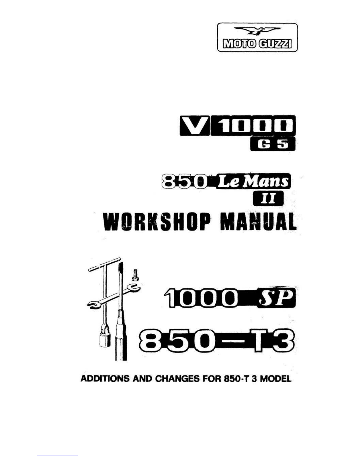
MOTO GUZZI V 1000 G 5, 1000 SP, 850-T3, 850 Le Mans II Workshop Manual
~JtiJJtdin
.
m
WORKSHOP
MANUAL
1
I
~
.
IO@
.
I
ADDITIONS AND CHANGES FOR
850
·T 3 MODEL
INTRODUCTION
Purpose
01
this manu lU is
to
give the
carrying oul .epairs In a rational
WBY
.
J'lecessary instructions tor overhauling
,,'
i
All data herein contained a
..
meant
10
give a general knowledge
01
the main
Checking operations
10
be done
wMfI
overhauling the different component
gloops
.
TO
lhis
IHId.
the
maOUllI
cMtaln'
many lIIustratic;lns. drawings. diagrams . and
taDies
to assist
you;"
lhe
siri
po,ng . checking. and assembling CJ9t!,allons.
ThiS
mllnual will alllO
U.
a guid
anc.
to. anybGdy who w1
shn
to
la'ni','II""
W,lh
lhe
manufactu.ing cheraclel isti
es
or
,ne vari
ous.,o
mllorn:nl pans ol Ine v 1000
Cii
5
end 1000 SP models. .
The
knowledge
01
tllese will
be
an ess .. ·.!· .. ,
lac\or
10'
perlo"'·.:
ng
a good job
AU
illus trations and des.,;riptlens in .
...
,~
manual should Ott ,ntended
a~
indicative
only
as 1he
Maflulaclur . .
..
, erve s
Itse!1 Ihe
"!oN
Ie
introduce
'1
any time and
wilhou
t Prier adv
ice
.ny
moditlcatlon il
ma,..
oeem usetul
tor
a belle. performance
e.
1m any olhe
••
OIIason
01
a conSt.uclional or cemmerclal natu •• .
NO
TE
The
term' . righ
t»
li
nd .I, tt. In
the lui lira
10
b, cOfleld
.,ed
a.
Mt1t
by
the
rid
..
H trida
'he
,""c
hine.
INDEX
1
.1
Sp,lfe
paris
1.2
Warranly
2.1
Mode
l v loc::l G 5
2.2
Model
1000 S
f'
3.1
Mo<!~1
V 1000 G 5
3
.2
IAod;"1 1000 SP
4.1
Engine
lUbrication
I
4.2 Aeplacir.g
lhe
oil
tiller
lilter
cartridge
and
cleaning
the
wire
gauze
4.3
lubricating
the
gearl>o~
4.4
lubrlcaling
1M
rear drive
I>o~
4.5
Fork
lubrication
4.6
lubrication
01
steeri
ng
bearings
ar>d swing
!Irm
5.1
Pan",1
board.
model V 1000 G 5
5.2
I
gnition
key ·
model
V 1000 G 5
5.3
Pan
el
board·
model
1000
SP
5.4
lighl
switch",s
5.5 Horn.
tum
lights
and
flashing
lighl
bultons
5.6
Engine slarting
and emergency
SlOP
butlon
5.7 Easy
slarter
I",v",r
3
,
5.8 ThroUle
conlrol
grip
5.9
Clulct.
conl.ol
leve.
5.10 Rlgt>\
Iront bra
ke
control
lever
5.
11
Twin brake
control.
I.ont
le,t and
rea.
5.12
Gea.shiit
ped
al
5.
13 Fuel filler
cap
5.
14
Fuel
level
5.
15
FlU,Il
tap · V 1000 G 5
model
5.16 Fuel
tap'
V 1000
SP
model
5.17
Electrovalve·
V 1000 G 5
5.18 Terminal
block with l
usu
5.19 Steering
loc
k
5.20 Side
stand
· V 1000 G 5
model
5.21.
Side
stand·
1000 SP
m<Jdel
5.
22 Steer
ing
damper·
1000 SP mOdel
6.1
Adju't
ing It.e
clutch
lever
play
8.2 Adjusting
1M
right
I.ont
brake
lever
6.3
Adjusting
Ihe
fronl
lelt
and rear
brake
pedal
6.5
Adjus
ting
Ihe
stee
.ing
6.4
Adjusting
tt.e rea. suspension
6.8
Adjusling
the
thronle
C001.01
grip
6.
7 Adjustfng the
.ear
wheel
spokes·
V 1000 G 5
8.8
Adjusting
Ine
headlight
beam·
V 1000 G 5
6.9
Adlusting
the
headhghl
beam·
1000 SP
11
.10
Rocke.
clearance
6.
11
Adjusting
the
double
contact
breakel
6.12 MainlenanCe
11.13
Cleaning
Ihe
wind s
hield
10
.1 Inll0dUCIlon
10.2 Removal
12.1
Rocker
covers
12.2
Sttipping
the
cylinder
heads
12.3
Cylinder heads
12.4 Valve
guide
s
:--
'
~_-:,::'.::"~_
-..t-~!'\
12.5 Vallie seats
12
.tI
Vallles
12.7 Checking
th
e inlel and exhaust valve opening
12.'
Inspecting tile vallie springs
12.9
Re
titl i
ng
the valve springs assembly on lIeads
12.10
Assembling the cyli
nder
barre ls
12.11
Refitting the cyl
inder
heads on the
cy!lnde~
12.12 Cyli
nder
barrels
12
.13
Pistons
12.
14
Piston rings ana oil scraper
12.1
5 Connecting rods
12.16
Fitting tile con-rods on cranksh a
!1
12.17
Cranksllal1
12.18
Checking the weight for engine balancing
12.19 FittJng tile flywll!l<!l on tile cranksllaft
12.20
Drive 5ide flange compl e
te
wilh
main journal
12.21 Seal for flange. drive side
12.22 Fitting
tile ftange c/w journal in crankcase. drive side
12.23 Assembling Ihe seal on timi
ng
cover
12
.24 Crankcase
12.25
Checking oil leakages from the crankcase
13
.1 Timing data
13.2 Diameter
01
camshaft bearings in their housi rlgs in crankcase
13.3
Tappetllu
ide in
crank<:ase
- coupling data
13.4 Assembl ing the crankshaft assembly. gears with chain on shafl,
engine-liming. oil pump
13
.5
How t
e.
change the chain IOn",'
o' 9"3r ",
i\h enoine assembled
on the
Ilame
13
.6 Valve timing
a.l
Oil deliver pump
14.2 Oil
sump
14.3 Replacing Ihe
oil filter cartri
dge
14." Wire gauze filter
14
.5 Oil pressure relief valve
14
.6
on
breather valve on the c'ankease piping
to
t
he
,e-cycling
device on
lilter
ass,y
14.1 Oil pressure solenoid
1
4.
1 Check ing the oil pressure wi
lh
engine
On
the byke
15
.1 Carburettors
15
.2 Float levelli ng
15.3 Adjusting the earburation and idling speed
.......
6
15
..
CMcking
ca,buratloOl
wllh
a
~acuometer
15
.5 Carbure110'
com~nent$
15.6 Replacing
tile al.
tilte.
ca.tridge
On
assembled
engine
16.1
Removing t
he
clutch assembly
16.2
Inspections
16.3 Assembling the
clutch
0!1
llywheel
11.1
Stripping
the
gea.box
11.2 Che<:king and
o~e'hauling
the gearbOX
components
11.3 Assembling the
gea.box
0!1 t
he
bench
11
.1
Remo~ing
the
gear d.iv"
box
16.2 Inspections
and
oVil,hauls
16.3 Re-assembly
2
2.1
Inspection
22.2 Removing the
bearings
trom
Ihe
swing
fo.k
22.3 Pressing the
o"Ie.
races
01)
the swing arm taper
bear"gs
22
.• Pre
SSin
gl!>e
beafings
inlo
the
R! H
a.m
01
the swing
tork
22
.5
Adjusting
the
swing
a.m
play
23
.1
Remo~rng
the
ttont whee l : Y 1000 G 5 model
23.2 Removing the
lront
wheel - 1000 SP model
23.3
Rear wheel - V 1000 G 5 mOdel
23
.. Rear whee
l· 1000
SP
mo<lel
23.5
Tires
23.6 Tensioning the wheel
spokes
· v \00 G 5
23.7
Wheel ba l
ancing
23
.a
Tire
temo
...
ol ond
rclltting
_ V 1000 G 5
23
.9
Tit" .ernoval
~nd
rehtlrng _ 1000 SP
2
3.1
0 C
heckIng
and
overhauling
the
h.eking.pitcui
t!
23.
11
Maste. cyli!"der lor rig
ht
IrOf't
bre~e
23.12 Master cylinder
lor
tell
If
On! and fear
bra~es
23.
13
Brake cal.per lor If
onl
brakes (modal V
1000
G
is)
and ra
..
bra-
kes (mode ' 1000
SPJ
23.
14 FtO<1I
b~ke
Clliper
lor
1000
SP
model
23.1S Braka ,.ads
23.16 Pipes
23.11
Bfa~ing
discs
23.1'
Braki ng
circllit
'allUs
23.19 Aacommandalions
24.1 Baltery
24
.2 Afternator-genaralor
24.3 Regllialor
24.~
Rectifier
24.5 Startar
molor
24.6 Ignilion system
:z.
.7
Alllomalic
altvane'
24.' Capacitors
24.9 Ignill
O<1
coil.
24
.10 Spark pl
l.lllS
24.
11
Twin contact braak
er
24.12 Assambllng I
Ma
breaker
0"
lMe
crankca
se
24.
13
Ignition
lim
ing
24.14
CMQ(:
king
tM'
Ignition advanCe (slatic + dynamic) using a 51robe
,,,
..
,
24.
15
Lig",
ing &qulpment end Morns· V 1000 GiS
24.16 ligMting equipment and l'Iorns
-1000
SP
25.1
legeno
- V 1000 G
is
model
25.2
legand
· 1000
SP
mOOUI
7
•
9
II
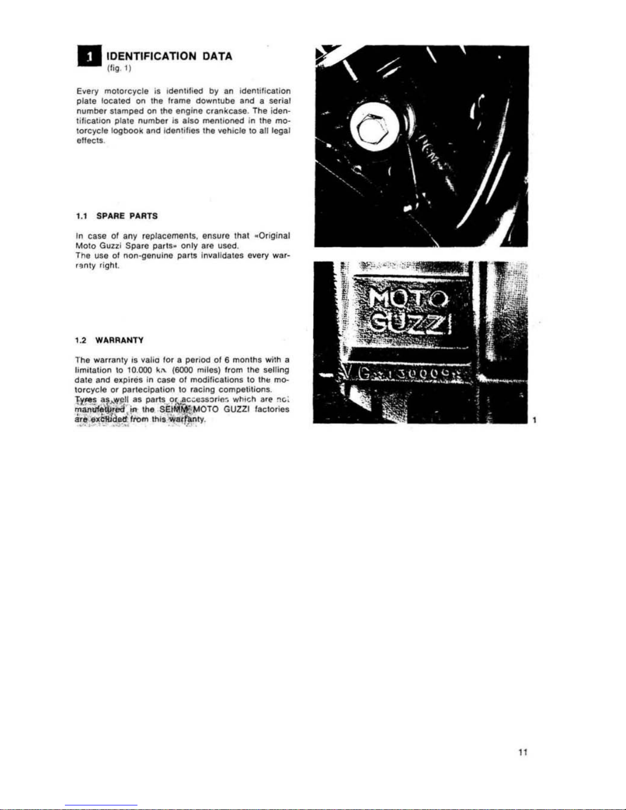
IDENTIFICATION DATA
(
fi\l
. I)
Every mOlofcyele
is
idenillied by an identification
plale located
on the
hame
downlube and a ser
ial
number ' t
lmped
on the en\line
c.an~case
.
The iden·
ti'lcation
plale
numbel
i,
allo
mentioned In Ihe mo·
to.cycle
1og1)OO~
and
Idenli';
es
tile vehicle 10 alltegal
ellects.
1.1
SPARE PARTS
In
case
01
any replacements.
ensure
thai _Original
Moto Guzli
Sp
•• e p.rts. only
Ife
used
.
Tha
use
ot
non-genulne parIS Invalidates every war-
,. nty right.
1
.2
WARRANTY
The
wa"ent
y " val
lo
for
e period
01
6 months
with
a
Ijm
,tallon to 10.
000
~,
..
{6000
miles) l.
om
the
,..
lIing
dale
and
.. pi,
8S
in
case
01
modilicallons to
thl!
mo-
torcycle
or parteeipalion to flcing cOmpe1ilions.
&:~.!
~t
..
"
!l~
as
partt, ..
o.
Jlc
~ .n:;.rl
flc.
wh,ch art
n<;
;
manuf~ea
in
the
SE~MOTO
GUlZI factories
1i'1II
e,,&ttid.ci;rom
1h1'
:
Wlr~ly
.
. .... l
••
_...
. .•
"
II
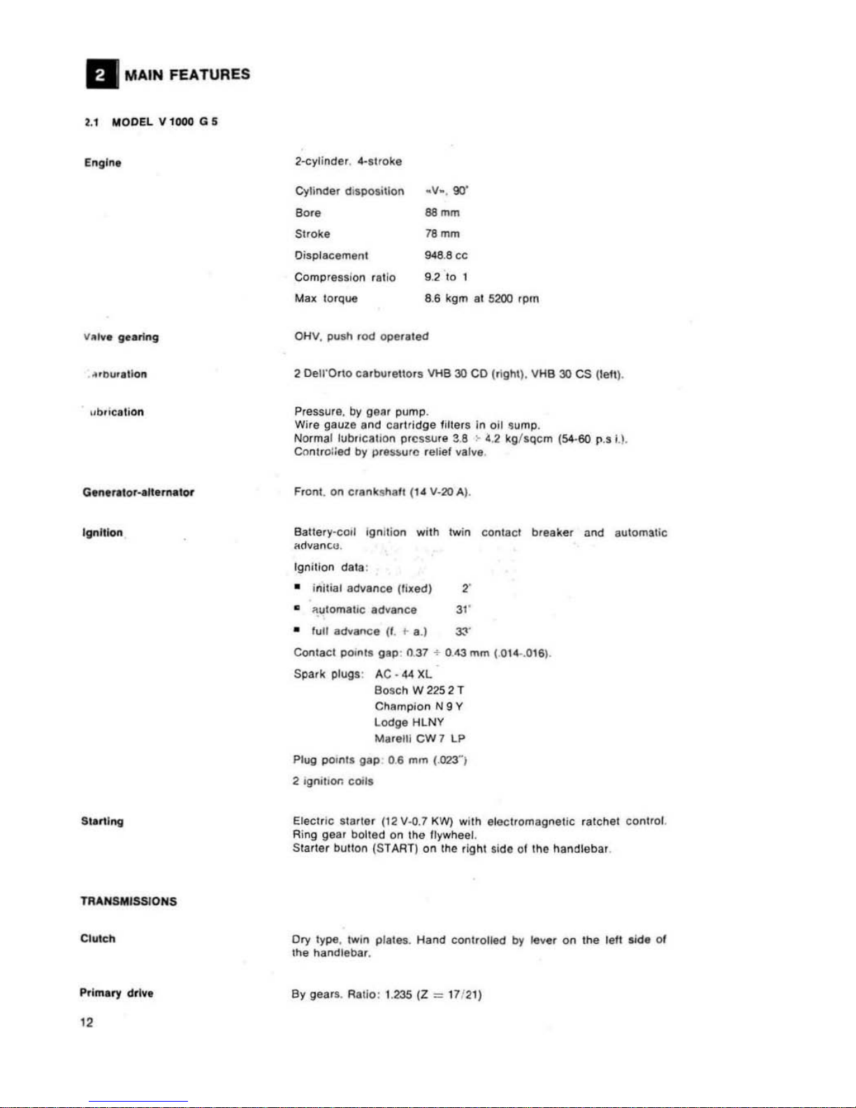
MAIN FEATURES
U MODEL V 1000 G 5
Mou"l1
on
Ignilloll
Stirling
TRANSMISSIONS
CIUlch
P
rlm.ry
dtlv.
"
Cyllnde. d i
spo$itlon
.'1-
, 90'
Bore 88
mm
Stroke
18
mm
Oispl'cement
9411
.8
cc
Compress
ion . alio 9.2 to 1
Mu
10'Que 8.6 kgm al 5200
.pm
2
OelrOrto c.rburellor
..
\tHe
30 co (right). V
HB
30
CS
(tell),
PreSSUlft.
by
ge~.
pump
.
Wire
gauze
a
....
d
cartlidg
e fille
lS
In
011
sump.
Normal
lub/lc.llon
ptcssure
3.8 ~ <1
.2
kg/'ClCm
(S-.5O
p ...
I.
).
ca
....
troiied by
pre»
urc
...
Iiel valve .
Fro ....
t.
on
cfanlu.h,ft
(14
'1,20
A).
Battery,co,1
Ig
....
,tio
....
wilh twin
con
lac.
breaker
a
....
d
automatic
a!!v"
.... uJ.
Ig
....
illo
....
dala
:
• i
nlt
;al
adv
.....
ce
(Ilxed) 2'
•
":c
utomallc
.dv.nce
31
'
• lull
adv,nce
(
I.
~
a
.)
3,.
...
Cont;W:I
pom"
gap
' n.
31
+ 0.43
mm
( 014..016).
Spark
plugs' AC, 44
XL
BO
$ch W 225 2 T
Chllmplon N 9 Y
LoO'ge
HLNY
M
..
elll
CW
7 LP
Plug
poinl'
gap
0.6 mm
{.023"1
2 'gni
bOl'l
coils
Electr
ic
'Iarter
(12 '14).1
KW) wilh
elecl.omagne\
ic
ratchet
conlrol.
Ring
gear
bolted
on
Ihe
Ilywhee
l.
Slarter
bullon (STAAT)
onlhe
righl
.ide
of
1M
handlebal
.
Ory type.
Iw
in p
r,,".
Hand
COl'ltrO
lllld by
III
....
on
the
letl
sid.
01
the Ilandlebar.
By
gea"
. Rallo: 1.235 (Z
==
11!2
1)
G ...
box
FRAME
8 ••
kH
P"rfor,.,..
nc".
Five-speedS. ConSlan! mesh
gear
wiTh
honlal
engagement
Ineor.
pora!;ng
eush
d';~.
Pedal
con!rolled
Irom
the U H si
de
01
!he vehicle.
Gear
ratios:
IS!
gear
-,
"
(14/
28)
2nd
gear
-,
: 1.388 (
IS
/25)
:lrd
gear
.,
: 1.047 121{
22)
41h
gear
-, ; 0.869 (23/20)
Hi
gh
gear
'"
1 : 0.
750
(281
21)
By cardan shalt and bevel
gear
set.
Ratio: 1 : 4.714
(7/33)
Overall
ra!ios
(engine·rear
whei!1)
1st gear
~ 1 :
11
.643
2nd
gear
..
1 :
..,.,
3rd
gear
- 1 :
6.095
41h gear
'"
1 :
5.059
High
gear
'"
1 :
..
""
Dup
re~
cradl
e.
!ubula.
sl.uc!ure.
Spoked
rims.
WM
3/2.15 ·
18
~
Front
: 100/90 H
18 (MT
18)
Rear; 110/
!>O H 18
(MT
18)
Tyre
pressure
:
Fron!. SOlo
riding
o.
with pillion 2.1 kg /em' (
30
lbs
s.i.).
Rear.
solo
.id
ing
2.4 kg/cm' (
34
p.s.l.)
wi!h
pllli""
2.6 kg/ ern' (
:>'7
p.s.i.).
The above
ligures
apply lor
normal
riding
(cruising).
If
using t
ha
moto(cyela
al
cons'~nl
high
speed
or
0"
highways.
it
is
recommen-
ded
1o inc.ease
pressure
by
0.2 kg /cm'
(3
p.s.i.
).
Front
, twin
disc brake
.
; i~~d
caliper
with l
wu
cylindCr"!:\. Hun!.!
con
·
Jr
olled
by
lever on the r'{jnt
hand
~1
:10
01
the
handlebar.
6'I'Kin
g
circuli
Independent trom
.ear h'''ke.
Disc 0 300
mm
(11.8").
Cylinder
dia. 38
rnm
(1.49'").
Ma
ster cyli
nder
dia . 12.7 rnm (.5").
Rea.; Disc
b.ake. 1001
cont.olled
Irom
Ihe
righl side
01
the
mOlO
'·
cycle
. DOUble
cylinde.
caliper
and hydrauliC hose.
Disc
dia. 242
mm (9.52-). )
Cylinder
dia. 48
mm (1.49··).
Masler
cyli""e
r dia. t5.
857 mrn
(.63
·)'
The rear
brake
is
hydraulically
connec
ted
10 a second fronl
blake
of sam
e type and
51~es
as the
hand
operated
Ironl
brake
.
Wheelbase
Le
ng!h
Wid th
Height
1.4
70m
2.200 m
0.850 m
1.1OOm
(58··)
(86.5")
(33-)
(46 ~
)
GrOllnd
cle
ara
nce
0.175 m (6.9'
·)
Grollnd
clearance
0.175 m (6.8··)
Dry
w..ight abt.
220
~g
(4
85Ibs)
Top
speed. so
lo riding
abt 190
~ml
h
1120
m.p.h.).
Fuel
consumptio
n: 5.8
Its " 100
km
(abt. 36 m.p.g.).
13

FUEL
AND
OIL
CAPACITIES
Group
or
pari
Fuel
lank
RlIsllrve (
wa/nlld
by light)
all sump
Ge
ar bo)(
Rllar drive bo)(
(b
e",,1 gear
lubrication)
Fron
l tork (each leg)
Brak
ing
circui
ls (Iron t and
.ear)
2.2.
MODEL
1000 51'
Engln.
v ...... g
..
rlng
Carbur.llon
Lubric
ati
on
G.nlr
al0r-Allirnalor
'IInltlon
"
QlIanlily
Recommendalion
24
I1s.
(S,S US gI
S.
)
I
Pe
lfol
9B
100
NO·
RM
4 us. (ab!. I
US
gL)
I
3
Us
.
(abt
3'
1,
qls
US)
Oil
_Aglp
Sint
2000 SAE 10 W
",
.
0.750
Its
. (abl 2S oz. USI
Oil _Ag
ip
F 1 ROira MP SAE 90.
0.250 Its.
(6
'h
oz.)
01
whi
ch
0.230
Its
.
(8
oz.)
0"
.
Ag,p
F. 1 ROI,a MP SAE
90
_
0.020 US.
('I,
oz
,)
I
Ag ip
Rocol
ASO 'R
0'
(
I M
ohkote
0"
type A
11080 lIS.
(2
Ol .)
Ag;p F.
1 ATF De
..
on
Ag ,p F
,
Br
ake
!iu>d
!ME
J 1703 B
Two-cy
l:n
der
. 4-slroke
Cylinder disposition _V
_.
90'
Bor
e 68
mm
Stroke
78
mm
Oisplac
eme
m 94B.8
cc
Comp
re~
s,o"
'auo
:J
2 10 1
Max
torql'e
8,{;
"gm
al
S200 ,.p.m.
Ol-iV, push (Cd o
peral_
.L
2
~II"Ol:')
carburellors
VHB.3O
c.:l
(right) VHB 30 CS
(Iell)
.
Pressure
, Oy
gear
pump
.
Wire
gauze and c
artrid
ge filter
s in
oil
sump
.
N
ormal
lubrication
pressure
3.8
->
4.2
kg/SQcm
(54-60
p.s.q.
Controlle(!
by
pressure
lelier
valve.
Front. on
crankShalt (t4 V -
20
A):
Sallery
-coo
l i
gnition
with twin
contacl
breaker
and
aulomatic
advance.
Ignition
data
:
I initi
al
adv
ance (fixed 2'
I
aulomalic
advance
31"
• lull
advance
33"
Con
tact b
leaker
gap
' 0.37-0.
43
mm (.014 + ,
DIS"')
.
S
park
pl"9!"
AC-44
XL
BOSCh
W
225
T 2
Ma,ef(i
CW 7 Lp
TRANSMISSION
C
lul
ch
0
...
boJ(
Ffl:AME
_.
Tlr
..
Bru
••
Champion N 9 Y
Lodge HLNY
Plug
points
gap
: 0.6 mm (.
0231
2 ignition coils
Electric Slarler (12 V -0.7 KW)
wilh
electromagnetic
ratchet
contro
l.
Ring gear
bolted
on
Ihe
I\ywheet
Starter
bUIIon
(STARn
on
thl! right side
01
the
handll!bar
.
Dry type,
twin
driven
plales. II is housed
on
Ihe lIywtleet. Hand
controlled
by
lever
on
the L/H side
01
the
handlebar.
By gears. Ratio: I to 1.
235 (17/2\)
.
S-speeds.
Constanl
mesh
gear
wilh
Ironlal
engagement
Cush drive i
ncorporated
. Pedal
controllad
on the LlH side
01
lhe
vehicle
.
Gear
ralio
:
Low gear
· ,
" 2
(14/IS)
2nd pear
'"
I
10
1388
(lS/25
)
3rd
gea.
· ,
101
.047 (21/
22)
41h
gear
e,
10
0.869 (23/
20)
High
gear
· ,
10
0.750 (2S/ 21)
Oy
cardan
shall
. bevul
gear
set.
Ral i
o: 1 10 ·U14
/7/
:;:3
).
CNerall
gear
ratioS (engine_
wh'lel)
:
Low gear
e'
"
11
.643
2nd gear
e'
'0
II~O
3rd
gear
~
,
'0
6.
095
41h
gear
e'
'0
5.059
Hi
gh
gear
m'
'0
..
'"
Duplex
cradle
. tubular
struclure
.
Ughl
alloy
cas
ling.
Rims
w~
3/2. 15-1S"
CP
2.
Fronl
: 100/90 H IS (
MT 18).
Rea.
: 110/
90 H IS
(MT 18).
Tire
pre
ssure:
Front.
solo
or
with
pillion
2.1 kg/em' /30 p.s.i.).
Rear.
solo
2.4 kg/cm' (
34
p.s.i.).
wilh
pillion
2.6 kg/Cm' (37 p.s.!.).
The
above data apply
for
normal
riding (cru
ising speea).
" using Ihe motorcyc
le
al
constanl
high
speed
or
on high ways.
Ihe
above pressure shoUld be I
ncre
ased by 0.2 kg/c
m'
(3 p.
!.i
.).
Disc
type
with
double
cylinder
caliper
. Lever
controlled
from
the
RIH
side
01
Ihe
handleba
r. Hy(!raullc
circuit
Indepen(!e
nl
fro
m .
th.
rear brake.
15

DI
.... n.lon. and
welg
hl.
FUEL AND
Oil
CAPAC ITIES
Group
or
pari
I
Fuel tan k
. ,
Reserve
DH
5Ilmo
G
....
bo
~
Rear
dn~
be<
Front lork
(each leg)
araking
ci
rcuils (l'Onl
and
rea
r)
.,
Disc
dia
. mm
300
(11.8/.
Cylinder dia.38 mm
(1.49
~).
Masler
cylinder
dia
. 12.7 mm
(.5~).
ANr
wheel
Disc
Iype
wilh
doub
le cylinder
hed
cali"er. FOOl
conlrolled
Irom
lhe
R/H "
de
01
Ihe byke.
Rear bra!!e
and
Ihe leI! I
rani
bra~e
ar
e in
terconnected
by a
hy_
draulic
circuil 8ctual
ed
by
the
s.ame
pedal.
Disc
dia .
242
mm
(9.52'"
Cylin
der
dla
. 48 mm.
(\.88
-).
Masler
cylinder
dia. 15
.867 mm (.
62
").
The
reir
bra~e
is
hy<l
faucally
connected
10
a se
cond Ironl
bra.ke
01 Ume
type and
~i
~es
as the
hand
operated
Iront
bra.
ke.
Wheelbase (loaded)
Leng
lh
2.
180m
(88"")
Wi
dlh
0.
750 m (29.5'1
Wi
dth
(incl. win
dsh
ield) 1.380 m (54" )
Min.
grou
nd
cle
arance 0.
175 m (6.9"")
Dry weig
ht
abl. 210
~gs
.
(
463
Ib!
)
Max
speed. solo
f'ding
abl.
200 km/h (125 m p.
h.l.
Fu
el
consumpHon: 5.
8115
)l
100
km (36 m.p.g.).
Qua
nMy
Recommendation
24 nF!
6 5 u s gls j
I
"e
l",1 98
/100 NO-RM
4
.1''''.
!fb'
1 US
gl·1
I
3 I". ra
bU
",
q:
s.
USAj Oil Agip SINT 2000 SA!:.
10 Wf'!IJ
0.
750 115.
(250~.
US)
Oil
Agip F. I.
Rm'a
MPSAE90
0.250
lis
.
(ab
!.
8'
/:
o~.J
oldluch
0.
230
115.
(8 oz.)
Ag'p
F. 1 ROtra
MP SAE
90
020
Its (,I: oz
.)
Ag ,p Rocol ASDI R oil
0090
115. (abl. 3 oz.t
Motole
oil
type _
.l
_
Ag
' F ATF
De~fon
. Ag,p D. I Srake
lIu,"
SAE J
110
3 B
II
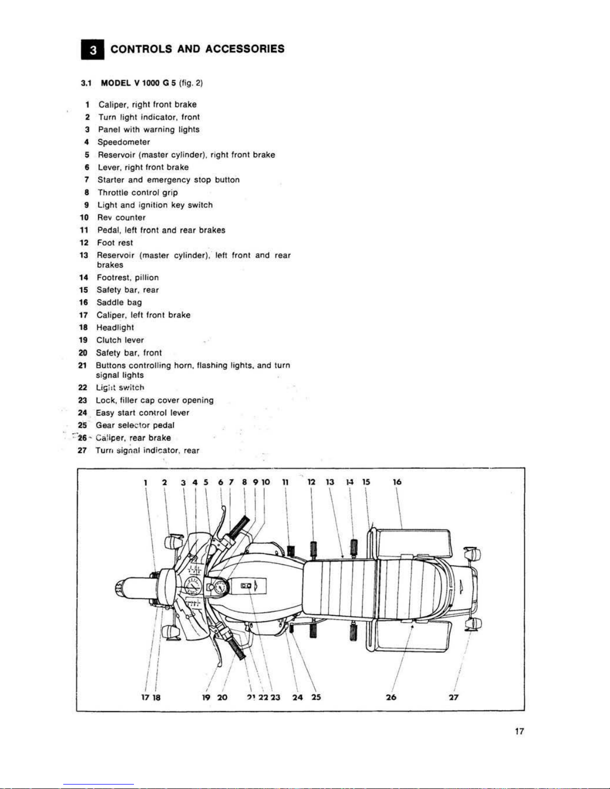
CONTRO
LS
AND ACCESSORIES
3.1
MODEL
V 1
000
G 5 (fig.
2)
Caliper.
righl
Iront brake
2 Turn fighl Ind
icalor. Ironl
3 Panel with warning lights
4 Speedometer
5 Roservoir (mast
er
cylind e
r), righl
fronl brake
, Lever, right
hont
brake
7 Slarter and emergency
SlOp
button
a Throttle control
grip
9 Light and ignition key switch
10
Rev
counter
11
Pedal,
lefl
front and rear brakes
12
FOOl
rest
13 Reservoir (master cylinder),
1(lI!
Iront and
feaf
brakes
14 Footrest, pillion
15 Safely bar, rear
18 Saddle bag
17
Caliper, left flOnl brake
18
Headlight
19 ClulCh lever
20
Sa
fety bar,
Ironl
21
Buttons controlling horn, !lashing lights, and turn
signal lights
22 U!i;'\
switch
23
Leek, tiller cap cover opening
24 Easy star, cOnlrol lever
25
Gear sel&elor pedal
~':l6
'
Caiij:er, rear brake
27
Tu",
signal ind
lestor
, rear
, ,
3456189101
1
\
Ii
! I
/ !
1718
, \
\ ,
I
/
"'''
"
22 23
13
~
15
"
/
I
!
"
"
,.
"
"
•
•
"
I"
,
' \ \ \
, , \
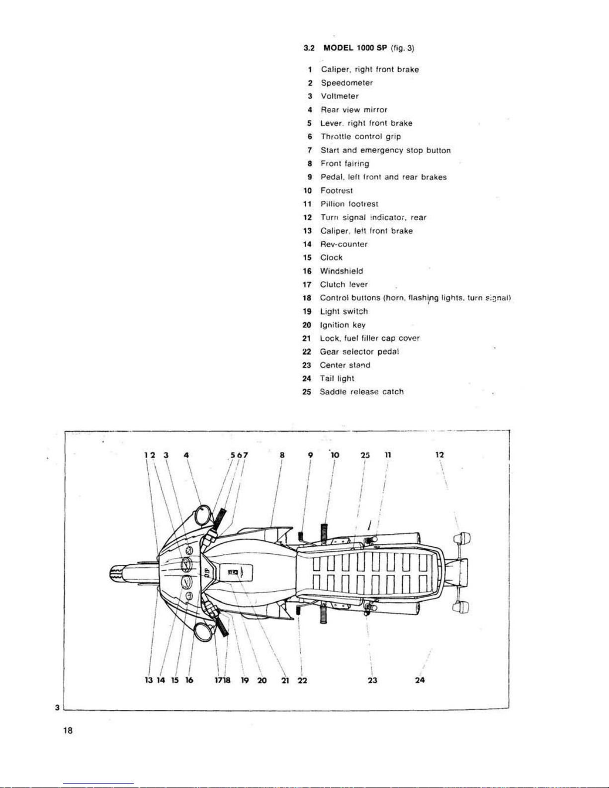
3.2 MODEL 1
000
SP
(lig.
3)
Caliper
, righl front brake
2
Speedometer
3
Voltmeter
4 Rear
~iew
mi
rror
5
Le~er
.
right Ironl
brake
6
Throttle
con
trol
gfip
7 Start
and
emergency stop
button
8
Front
l
al,,~g
9 Pedal, leI! front
and
rear brakes
to
Footrl!st
11 P,itiO'l 100heSt
t2
Turo,
sig
nal tndicato;,
'ea,
13
Caliper. lel1
front
brake
14
Ae~·counte,
15
Cloc
k
16 Windshteld
11
Cfulch
fe~er
18
Cootrol
bul100s
(horn
, 111I,h1'g 1i9"rs. turn
",~nall
19
Light
sw;'~h
20
Ign
itio
o key
21
Lock,
fuel Imer
cap
cover
22
Gear selector
peoai
23
Cen
ter
,ta~d
24 Tail light
25
Sadore release
calch
•
,.
"
n
I
I
,
,
I
,
,
,
I
I
I
I
,,--~
l
\
I
\ \ .
\ \ \" 1
17;8 19
20
u
),
,.
,
L-
____________________
________
______________
~
"
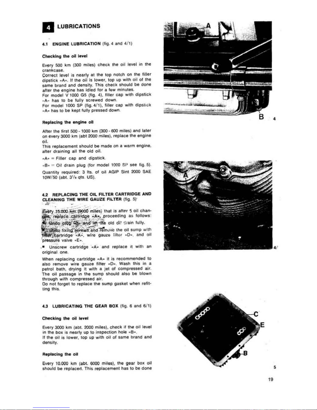
a LUBRICATIONS
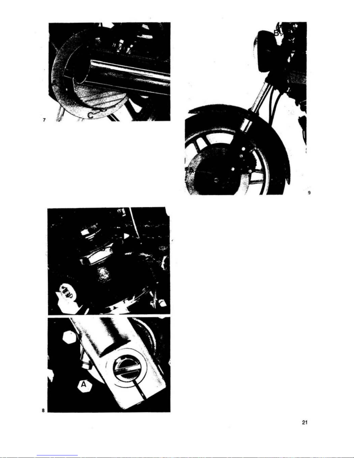
•. 1 ENGINE LUBRICATION (Iig. _ and . /
1)
ChKklng In.
011
1.vel
EY4Iry
500
km
(300
miles) check the oil level
In
the
crankca.a
.
Correct leval
it
nearly at the top
nolch
on lhe IIIler
dipstick ' '''
'.
" the oil
15
lower.
109
up with oil 01 Ihe
sam.
b'lInd
and densiTy. This check ahould
be
done
atte. Ihe engine has idled
lor
a lew minutes.
For
model V
1000
G5 (Ilg.
_I.
liller cap wi
th
dipstick
. A· h
as
to be
lully
sc.ewed down.
Fo.
model 1
000
SP (lig
. 4/1). liller cap wilh dlp5\
ICk
.A.
has
10
be
kept lully p.es sed down
Raflla<:lng ltIa
...
glne
011
Arter Ihe
lirsl
500·
1000
km
(300·
eoo
mUesl and later
on
eY41ry
3000 km (
abt
2000 miles). replace
the
engine
011
.
This
'epllcement
should
be
made on a warm engine.
atter draining all
the old oil.
· A .
..
Fi1!er
cap and
dip
stick .
• B .
..
Oil drarn plug (10' model 1000
Sf'
see Ilg.51.
O"a:"llity
.equi
red : 3 !Is.
Of
oil AGIP Sl
nl
2000
SAE
IOW/5I:J
(.bt. 3'1
.
Qt
s. US) .
•
.2
REPUCING
THE
OIL
FIL
TER
CARTRlaGE
ANO
a.EAHING
THE
WIRE
GAUZE FIi..TVI (fig. 5)'
~
;r,...'t-!~~
~
~~
tn!IeS} Ih.1
i.
~"f"
5
011
ch.".
m
"~l.c.:Wtr~, .A~.
p.oceedlng
..
lollow.
:
::li!.~ -
?~
1
•• --.
C$."
"\
" 1
~
.: ,.O;
.fl~~~i~_-tl\e
old
dH
~,.in
tully.
~~~
1I~liul
~
~;"j:S-
:~dTe'm
"vc.'he
oil sump with
~1'i-':;'ndge
. A •. wife gauze
r,It"
• • 0. , and
011
'
pteMme
v.lve
. E •.
. _ UnScrew cartridge
.A.
and replace II wlth an
o.igln.1 one.
When
.eplacing
clirtridge . .... it il .ecommended
to
al!-D
remove wi.e gauze lilte
••
0 • . Wash this In a
pllrol
balh. drying i, with . Je'
01
comp.essed
.Ir
.
The
011
passage In
the
sump should also
be
blown
through
wilh
com
pressed
.ir
.
00
not
lorget
10 .eplace
the
S4.1mp
gastll
w".,.
reli t-
ling
th
ll .
4.3
LUBRICATING THE GEAR BOX (Ilg. II and 6f
l)
ChKklng
the
011 lav,r
EWlry 3000 km (ab!. 2000 miles). c
hKt
II
,
he
oil
te~el
in tha
box
Is
filiI/tv
up
to inspec1ion hole
·B·
.
II the oil is lower, t09
up
with
on
of sarna b
••
nd .nd
densIty.
Rapfacl"ll
,he
011
E¥
.ry
10
.000 km
,a
l>l
. 6000 milesJ, the gear box oi'
should
be
repl.c
...
. Th
iS
repl,cemen ' has '0
be
done
•
,
"

•
20
on
a w
arm
eng,.,.
as In
I~cn
condlUon
Ihe
oil
is
lIuid
and
mo.e
easy
10
dr.in. 00
not
lorg
el
to leI
the
old
011
dr.i" tully
~tor.
any
t.esn
one
is introduCed .
• A-. I
iller
cap
_
·
8·
- inspect;OfI hole
c'l)
.
•
C. -drain
plug
.
Quantity
reqo.med: 0.750 Its.
labl
. " 1.
pints UI)
AGIP
F. 1 Rot
••
MP
oil
SAE 90.
'U
LU8RICATION OF
REAR
DRIVE
BOX
(lig.
7)
E~ry
3000
km
(2000
mile.)
en$f.l'.
Ine
oil level Is
nearLy
up
to inspe<:.ion
hole
. A •.
II
10_.
, lOP
up
with
oil
of
same
hrand
and
densIty.
EVilry 10.000
km
(6000
miles)
replace Ihe
oil
in
1M
fear
drive
box.
Thi.
replacement
i.
best done
on
a warm englrle
when
the
oit II
easie
r to
be
dr'ined. let
the
old
011
d
••
,n
h,lly belo
••
adding
I,e,h
oil
_A_
level
COrll.ol
cap
.
_8_
"lie.
cap.
-c·
Drain plug.
Quanlity
req"';re(l' 0.
250
lis
.
(lb!
. 8
'h
o:z)
01
wh
ien
0.230 Us.
(abl
. 8
011
Oil
of.IJ
lD F. to Rot
••
MP
SAE 90
and
II
•.
0.020
(abo
ut 'f:
01)
"gip
Rocol
"SO
IA. (M
o-
Iyko,e
'vpe
.A_I
.
To
replaer
,ne oUln
the lork
legs.
proceed
U"
l
ollo"'~
:
• ·
Undo
drain
plug
""Ih
gaske
t
·A_.
• UndO
0011 .8_
.
Belore
imrOOu-ting
Iresh
oil.
lei
Itle
lo
rk
legs
drain
lullV
·A·
Fluid
drain
Kreft
.
·8·
Fhlld
Iiller
cap
Quamitr·.eq
uot
ed 0.
090
It.
(aol.
3
oz
.!
each
leg Oil:
AGIP F 1 A
TF
Ouron
Lubrication
01
th
.
""
"n;
I
nd
ru r
'ork
bu rlng.
For
Ihis
operatIon
use
. AGtP F 1
Grease
30_.
21
22
II
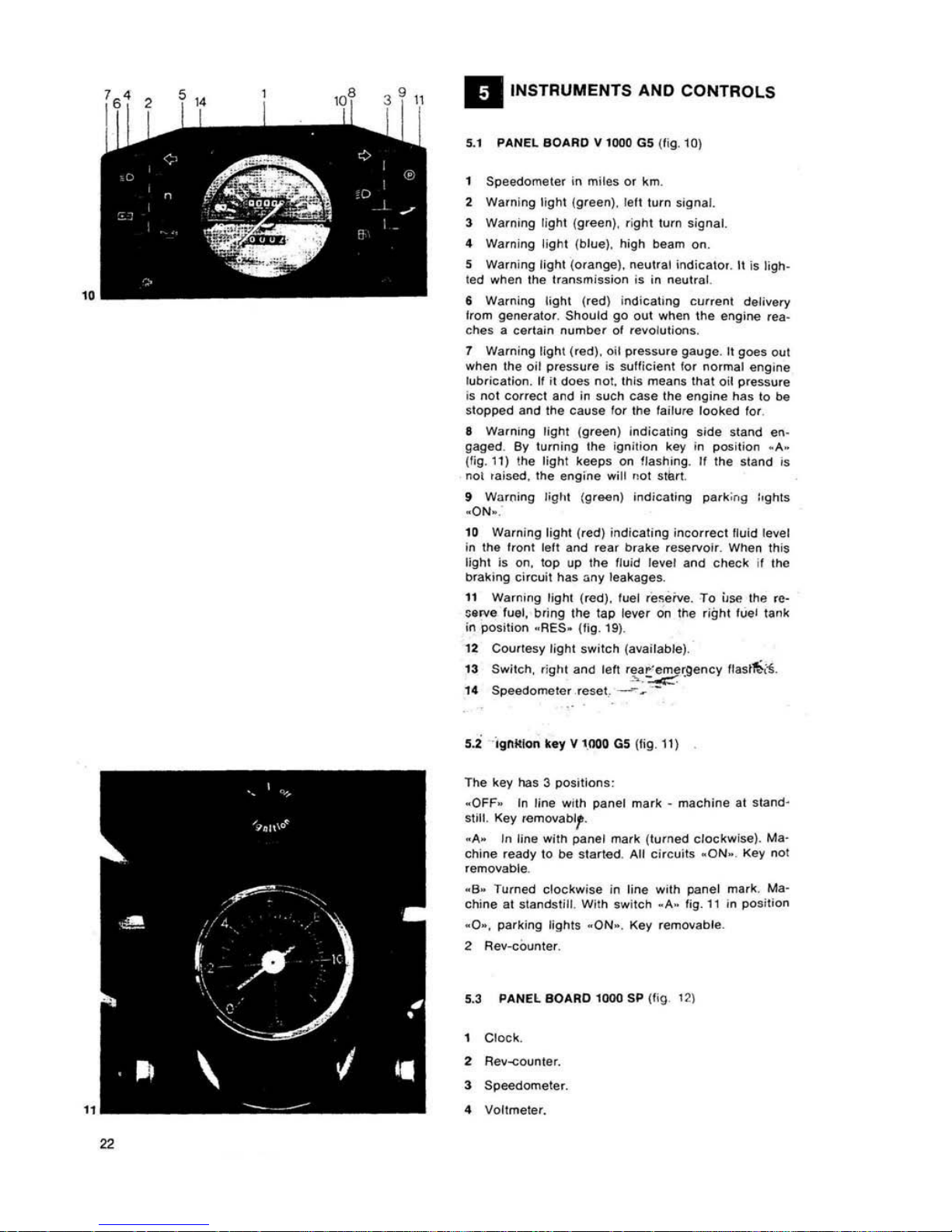
INSTRUMENTS AND CONTROLS
5.
1 PANEL 80ARO V 1000
G5
(Iig. lQ)
Speedome t
er
in
miles
Or km.
2
Warning
light
(g/een). le
ll t"rn
signal.
3 Warning
light
(gre
en). ,
igh
t lUI/)
signal.
.. Warning l
ight (blue)
. high beam
on.
S Warning
light (o.
ange). neutral
;odieal"
•.
II
is
ligh.
led
when the
'ransmi
ssion
is
in
neulra
l.
&
Warning
light (red
) i
ndicahng
cutren!
delivery
I,om generalor, Should go out
.....
hen the engir.e lea-
ches a cellain
number
of
.evolutions
.
1 Warn
ing
Ugh\
(red),
oil
pressu'B
gauge
. II goes o
ul
when the
oit
pressure
is suUielenl 10'
no,mal
engine
lub.icallon.
II
il
does
not.
this mea ns tha I oil
pressure
is
not correct and in such case the engine has to
be
stopped and the cause
lor
Ihe
lallu
,e
looked
fo'
.
I
Warning
light
(gree
n)
indicating
side
sland en-
gaged
. By turning the
ignitio
n key in position .1'..
Uig.l1) (he
light
keeps on lJashinll . " the stand
'S
not
raised.
The
engine "ilt
no
t
$Iurt
9 Wo..ning
ligl,t
(g'9&n) IndicaTing p
arking
t'ghts
.O
N_.
10 Warning
light
,red)
indicat
ing
inco
rrect
lIuid level
in
the
I
.ont
lett
and rear
brake
reservoir. When thi,
ligh(
is
on. lOp up
the
Iluid level
and
check
il
tM
braking cir
cuit
has
any
leakages.
11 Warning
light
(red).
luel
re~eive
.
To
use
the re-
~8
rve
lue
t,
bring
Ihe
lap
Ie~r
on
Ihe
right
luel lank
in
position
.RES.
(lig.
19)
.
12 Courtesy
light
swi t
ch (availab
le).
13
Switc
h.
fight
and
lelt
.~~~
•.
gency
l t
ast~~.
,.
S~ometer
reset
, - _ --
s.i
ignitIOn
k.~
v 1
00
0 G5 [I
ig
. 11)
The key
has 3
positions'
.OFF.
tn
line w,th panel
mark -machine
at
stand·
stilt. Key remova
bl,.
.A_
III line with panel mark
(turned
clockwise).
Ma-
chine
ready
to
be
statled
. All
circuits .ON·
. Key not
removable .
•
S.
Turned
clockwise
in line with panel mark. Ma-
chine
al slandstill. With switch .1'._ lig.
11
In pOsition
.0_.
parking lights .ON
_.
Key removable.
2 Rev-counter.
5.3 PANEL BO
ARO
1000 SP
[fig
12\
Clock
.
2 R",,-.::ounte
•.
3 Speedomete
r.
4 Voltmeter.
S Ignition key:
.O
FF_
In
line
wllh
panel
ma.k
_C_
. Millehine at
$Iandslill. Key
'emovab
le
.
•
A_
In
tine with panel milllk
-C-
(Iull'led
clockwile).
All
cilcuits .ON_
. Key
not
removable.
·6.
In
line with panel
mark
_Co
.
Machine
at atand·
,1111
. With switch - A· In fig.
t3
in
oOll
itlon . 0 _. par-
~Ing
light on.
Ke~
removable.
S
Waln
ing
light
(green).
lell
lurn light
.
1
Walnmg light (orangel i
ndiu!ing
gearbo~
1II
neu-
Iral.
lights
up
wtoen
gearbol
is
in
neutra
l.
•
Warni
ng light (.ed
) indicatong
current
delivery
Irom
generato
•.
Should
IJO
out
as
soon as the
engine
reaches a c .. rte
in
number
01
revoluHon •.
It Warning lignt (redJ.
0,1
plenu.e
gauge.
Goes
oul
whan oil
p.essura
Is ,ull
ieianl
lor
normal engine I
....
bticatlon.
II not.
11'1"
means
oil
pressu.e Is incorrect
In
such case tha
engine
should
be
immedlale
l~
IIOP-
ped
and
the
cluse
10. the
laull
looked
lor
.
10 W,I.ning
lighl
(red) ,
ndicating
incolfect
lluid
level In
Ine
Itoot
and
rear
b.ake
reservoir. When this
lig
hl is on,
top
up
the
fluid level
Ind
check
the
bre
-
king
eilcu,l
10'
leakages.
11
Warning tight (blue). high- beam on.
12
Warning light (gleen).
perking
light
s
00
.
n Warning light (green). right
lurn
s'gnill
.
14
Sw,teh.
nght
.nd
lelt
lea'
emergency
lIashoe".
15
S~omelel
zero
.esel.
5.
4 LIGHT SWITCHES
(119.
13)
Ale
loc"to.;d on the
lell
·handle-bel.
Swi
tch d,.
• Posit
...,,,
:':) .
.. pai
kill9
tights.
• Position _I ·
- Iwo-tight
lamp
-ON-
.
•
Posit,on
.2.
- li
ghts
all
.
Switch _8.
With switch ·
A·
In pOlltlon
_h:
• Position
·4.
_
lo
w beam.
• Position
.5.
~
high beam.
5.
5 HORN. TURN
LIGHTS
,
AN
FLASHING
U G
HTS
BUTT
ONS (Iig. 13)
Ale
located
on
the lelt
handleba
r.
Bu
llon
wC.
•
5 (
hCHn
Dullon).
• 6 (liasn)
Ilashing
~ght
Dutton.
• 7 lett turn signals
conltol.
• 8 ' Ight tUln
signals
con \rol.
"
23
,.
"
16/ 1
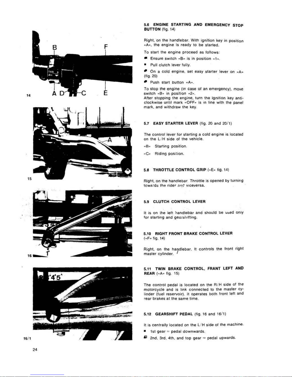
5.6 ENGINE STARTING AND EMERGENCY STOP
aUTTON
(fig.
14
)
Right, on I
he
handlebar. Wilt>
Ignllion key in positi
on
.A.,
the
engine Is
ready
to
be
'!
tarled
.
To start the engine proceed as follows:
• Ensure
!wi,eh
. 8.
is
in posi
tion
. 1
.,
• Pull
clutch
lever
fully
.
.,
On a cold engine, set ea
sy
sl,
'IIt
er lever
On
.A.
(f
iO·
20)
.,
Push 5ta,t
buttoo
. A
·,
To St
op
the
eng ine (in cese
01
an
emergency). move
switch
.B·
In po sition
.2_
.
Aller
stopp
ing
the
..
ngine. 1u,n the igni
tiOn
key
anti
-
clockwi
se
unlil
mark .OFF
. Is in li
ne
with the
panel
mark, and
withdraw
the key.
5.1 EASY STARTER LEVER (tig.
20
and
201
1)
The canUel level
fo,
starUng II
cold
engine
is located
on
the L/H
side
of
the
vehieie.
· a . Slam"'g position.
-C-Riding
PQs;tion.
5.8
THROTTLE CONT
ROL
GRIP I·E·
fig.
14
)
RighI.
On
tile
handleDa, Th,Ol1le is opened by
Iv.olng
low",d~
tl')"
fIde'
"0<;'
Vlceve'sa.
S.
t CLUTCH
CONTROL
LEVER
It
is
on
the
~U
hanOleba. aod
should
be
""ed
OnlY
10. starUng and
g
ea~IOI
lt1ng.
5.10 RIGHT FRONT BRAKE CONTROL LEVER
(-f
' . rig. 14)
RighI. on the
ha7dleba
•. It COl\trolS the I.onl righl
masler
<:yflode •.
5.11 TWIN BRAKE
CONTROL
, FRANT
lEFT
AND
REAR
(-A-lig
. 15)
The
cont.ol
pedal
is localed
00 lhe R/H
side
of
Ihe
mOlorcy<:\e and
is
link <:"ooe<:Ied to the
masle.
cy-
linde.
(tuel
reseNoir)
.
11
operates
both
1'0'11 len and
.e
ar
brakes al
me
s.ame
time.
5.12 GEARSHIFT PEDAL
(fo
g.
16
and 16f l )
It
is <:eo
l,ally
lo<:ated
()(I
the LlH side 01 the
machine
.
• 1st
gear
..
pedal dOwnwardS.
iii
20d.
3'd, 41h,
aod
lOP
gear
..
pedal
upwa.ds
.
Betore
changing
gear
, II is
necessary
10'
the
clutch
leve,
to
be
pulled
fulty in.
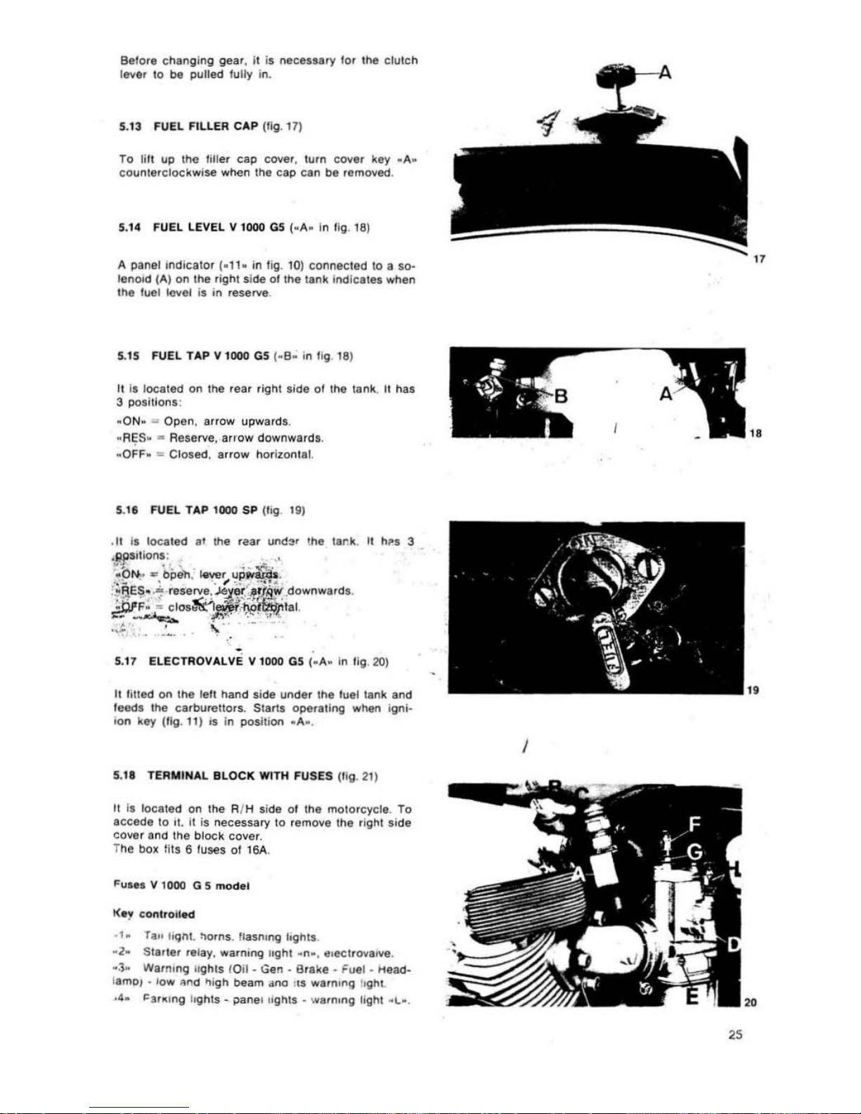
5.13 F
UEL
FILL
ER CAP
(tig. 17)
To li
ll
lip
Ihe
liller
cap
cover. turn
cover
~ey .A~
eounterelockwiH
when
Ihe
cap
can
be
removed
.
5.14 FUEL LEVEL V 1000 G5 (_A_ In t
ig
. 1
8)
A
panel
Indic
ator
(_
11.
in
fig.
to)
COOl1ecied
10
a 50-
IenOfd (A)
on
the
right
side
01
the
tank indle,tes
when
the
tuel level
il
in
reHrve
.
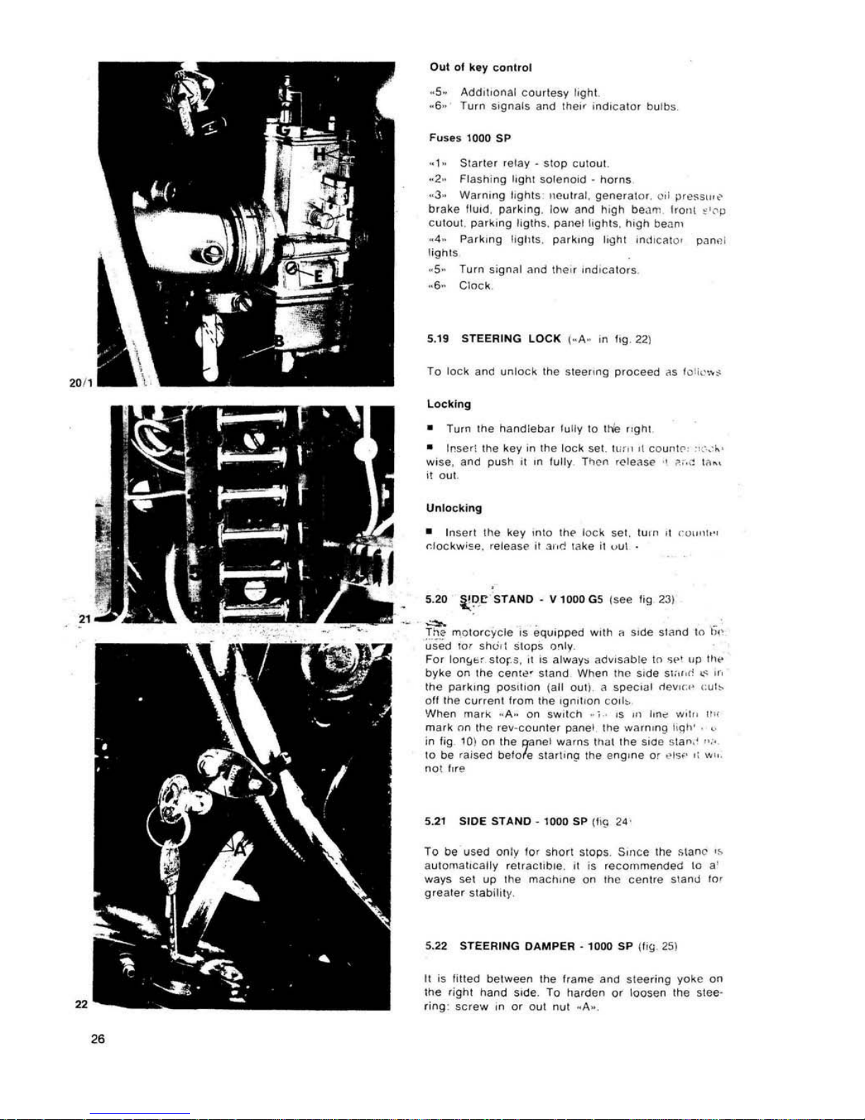
5..5
FUEL T AP V 1000
G5 (.B.
in
IIg
. 18)
II II
located
on
the
rear
rignt
side
01
the
tank
. It has
3
POsitionl
:
-ON-
..
Open.
arrow upwards
.
-
R~5
.
..
Reserve.
arrow downwards
.
• OFF .
..
Cl
osed.
arrow horizontal.
5.11 FUEL TAP 1000 SP (I
ig 19)
5.
17
ELECTAOvALv e V 1000 G5 (_A_ In
lig.2O)
It totted
on
the
lett
hand
side under
Ihe
luel
tank
and
feedl
the
carburettors_
Starts
operating
when ignl-
ion
key (fig
. •
f)
Is
In
position
.A
•.
5.11 TERMINAL
BL
OCK WITH FUSES (Iig.
21)
It Is
located
on the AIM side 01
the
motorcycle
. To
accede
to
,t o it is
necessary
to
remove
the
right sid
e
cover
and
the
block
covel
.
T
he
bo~
tits
6 fuses
of
16A.
Fu.,.
V 1000 G 5
mod,1
1(
'1
clHllfolled
·
1.
ra" loqn!.
:'OtOs. Uaslung
I.ghll
.
·2·
S"'
tel
..
fay.
warn.ng
light
. n
•.
tI,ectrova,ve.
·3~
Warntng IIghlS lOil _ Gen _ iJraka _
Fuel·
Head.
I
.mo/
• l
ow
"Irn.1
.,i
gh
beam
.mo tiS
warn"'g I.ght
.4.
"'ar~'ng
li
ghts
- paner ,ights _ warn,ng
light
. L_ .
"
"
I
2S
"
Oul
of key
control
.5.
AddItIonal
courtesy
I.ght
-6"
Tu,n signals
and Ihe" i
ndIcator
bulbs
.1.
Sla
rier
relay·
Slap
cutout
,
·2
· Flasr.ing lIght $Oleno<(I .
homs
·3·
WarnIng
l'ghtS
neul,at,
generator
0,1
press,",,'
brake flu.(I.
parkIng.
low
and
~Igh
be~
'I1
1r0ll'
~'''P
c
uto
ut.
par~,"g
liglhs. pan(ll
lightS, hIgh
be.:!",
. 4·
Pa,k,ng
I1gIlIS,
park,ng
IIgnl
InlfI
C~to'
p.ln~1
li
gnl5
-
s-
Turn
si
gn~1
and
the" ,nd
lcalors
.
Clock
5.
19
STEERING
LOCK j-A- in IIg.
221
To
loc
k and
unloc
k the
steelIng
pfoceed
~s
l"Ii~""$
Locking
•
Tu,n
Ihe
nandleb~r
tully
10
tile
"gol
•
Inser\
the
key'"
the
lock
set
HI
."
,\
co
ur>'
('"
'1,'._
,.
wise.
and
push
,I ,n
tully
Then ,ele<lM' ·r
~;"'
:
""
..
i!
out
.
Unlocking
• I
nsert
the
key
,nlo
In
..
l<>ek
sel,
luln
It
'"u
,,"'h-,
r_lockw;~'l.
release It
3"d
lake
il
vul
5.20
i;!>
.C STANO - V 1000
GS
IS<*!
Hg
231
~
.
Tila
mOlo.c
yele
IS
equipped
Wllh
!l
Side
sland
In
""
used
10.
shUll
SlOPS
o"'y
.
For
lon!<~'
SIOr-
S.
,I
is
always
adVisab le
III
~,.,
"p
tlw
by
ke
on
the
een'<!" Siand When
Inc
Side
SIC,,,rl
..
~
or
.
Ine
parking
poSLlion
(a
ll
oull
a spee,;,1 <lev
",.'
"lib
oft
Ihe
eurrenl
Irom
Ine
'gn,l,on
CO'I~
When
m~rk
· A
..
on
sw,leh
_\ .
'5
,,'
Ion",
",.,,,
",'
mark
nn
Ihe
rev-
counler
panel
Ihe
warning
"
Ilh'
.
in fig
10
) on
Ihe
I¥nel
warns
Ih~1
Ihe
sloe S
la"
,' " "
10
be rais ed
belo
le
Slarhllp
the
engine
or
,"S''
Ii "'"
nOt fI,e
5.
21
SlOE
STANO - 1000
SP
II'!; 24 '
To
be
used
only
lor
shOrl
SIOIlS. Smce
Ihe
Mane
,~
aUlomal,cally
relraCllble
.
II
IS reeornmend!t<l 10 a'
ways
sel
up
Ihe
mach",e
on tho
centre
stano
to'
g,eate'siabill
ty.
5.22 STEERING DAMPER _ 1000
SP
(
I'g
2S)
It is IjUed
between
lhe
hame
and Slee
,ing
yoke
on
Ihe
"ghl
hand
Side. To
Mrden
0'
loosen
Ihe
stee'
,ing' se,ew
,n
or
oul
nut "A_.
"
"
"
ZT
"
28
II
MAINTENANCE OPERATIONS ANO
ADJUSTMENTS
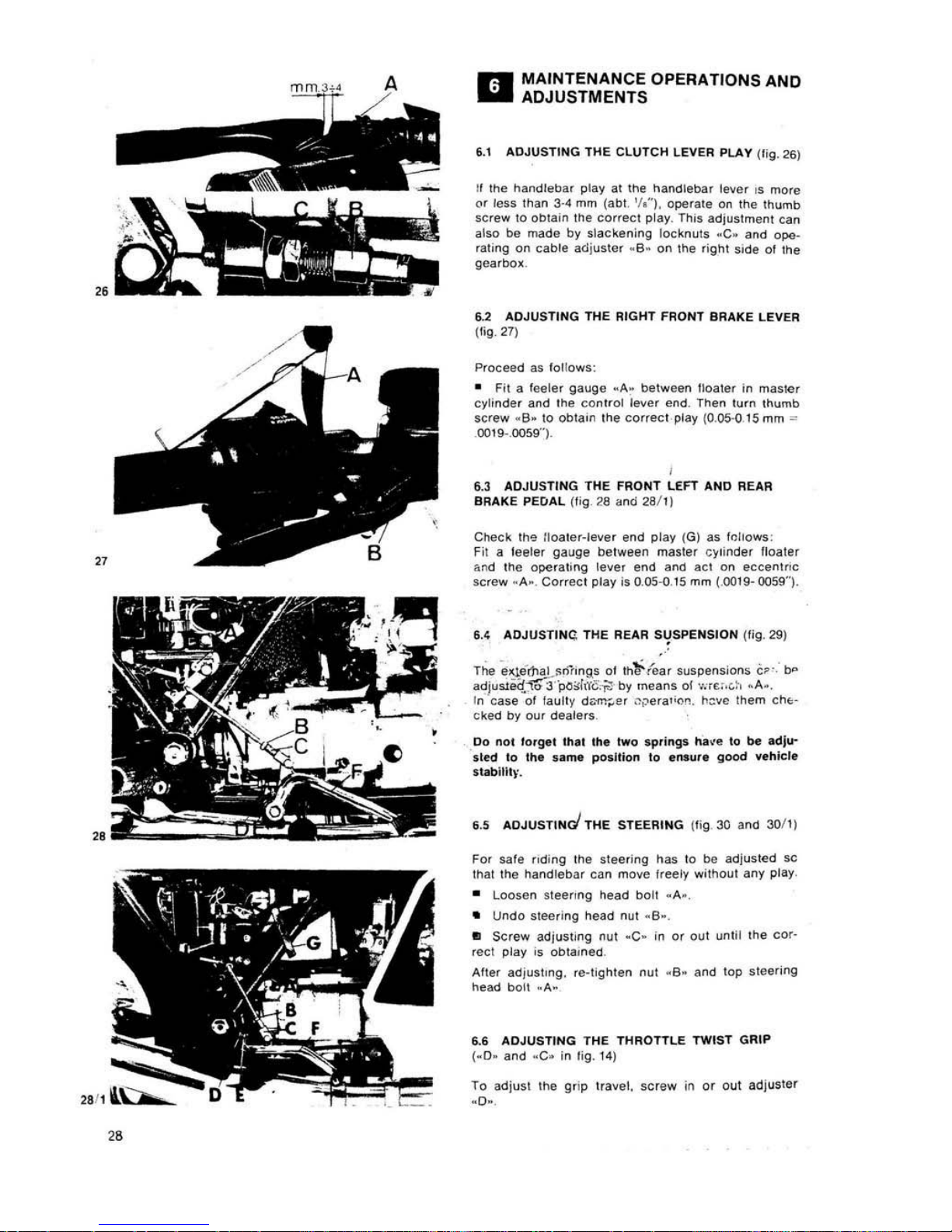
6.1 ADJUSTING
THE CLUTCH LEVER PLAY /tig.
26)
If
the
handlebar
play
at
Ihe
handlebar
lever
IS
more
Of
less than 3·4 mm
(ab1.
'/
0 . operate
On
the thumb
SCrew
10
obtain
the
COrreCt play. This
adjustment Can
also be made by slackening locknuts .C_ and ope-
ra
ting
on cable
adjuster
. 6· on Ihe
right
sIde
01
Ihe
gealbo~
,
6.2 ADJUSTING TH E RIGHT FRONT
8RAKE
LEVER
(Ii
9_
27)
Proceed as tollows:
• Fit a
fee
Ie.
9auge
_A.
between
Boate, in maSler
cylinder
and the
control
I"ve.
end
.
Then
tur
n t
humb
sCrew .
B_to
obtaIn the COfreCI play (0.
05.(1
15mm
'"
0019-.0059'').
,
6.3 ADJUSTING THE FRONT LEFT
AND
REAR
BRAKE
PEO
AL
(tig
26
and 2a/
l)
Check th'"
Iloaler-leve.
end play (G) as ,,,!tows :
Fit a
lee
ler
gauge
between
master
c~linder
lIoaler
;;.rId
Ihe
operating
leve,
end and
acl
on
IIccllnlnc
screw
·A
•. CorreCI play
is
0.
05-0.15
mm (.0019- 0059").
6.4
ADJ USTING THE REAR S,!SPENS
ION
(Iig. 29)
"
The
~qe-mal
~nh
nQ.S
01
lhl-fea,
suspens;oos
C~
·.
b<>
adjusJ.eq1<ri
·
i><l;r(j
c~
by
means
of · • ..,6'
.C
:-.
.A_.
In case 01
laully
d.",.,..er .1;.>era';<')n
. h::vc
them
Cht·
eked by
our
dealers
.
Do
not
lo'ge
t th " Ih" Iwo sprin
gs
h a~e
to
be
adl'"
,
tet:l
10
the same pOsition
10
elllu,e
Oood weh
icl.
slabilil~
·.
6.5 AOJUSTINd THE STEERING (
tig
30
and 30/
1)
For safe
flding
Ihe stee,;ng has 10
be
adjus
ted
lie
that
Ihe
handl
ebar
can
move
Ireely
wi t
hout
any
ploy
•
Loosen ste
enng
head
boll .A_.
•
Undo
steering
head
nut -
6-.
•
Screw
adjuSlmg
nul
-C-
in
or
oul until
Ihe
cor·
reel play
is
ODlalned .
AHer
adjust
ing.
,e· tighten
nut
_6 _
and
lOP
sleering
head
bOil _
A.
6.6
ADJUSTING
THE
THROTTLE
TWIST GRIP
(_D_
and -C. in
lig. 14)
To
adjust
Ihe
g"p
travel.
scre
w in
or out
adjuster
_D·
.
"
TO
adjust the
grip
retum, screw
in
or
out
adjuster
~C_.
6.
1 ADJUSTING THE
WHEel
SPOKES _
II
1000 G 5
Ensure
that
all spokes
are
property ten
sion
ed and
thai
Ihe
wheet
rim
is
quite
true.
PrOCeed
as loliows:
•
Turn
the
wheel
alld using a
locator,
check
it the
wheel
is
ollsel.
II
necessary
tighten Or
loosen
the
right
o.
tell
spo
kes
!iii
the wheet
turns
withoul an1
wotltlling. Tllis
chec
k S
hould
tie dan(!
after
the first
500 km (300 miles) and
IMn
every 1500 km (goo
miles).
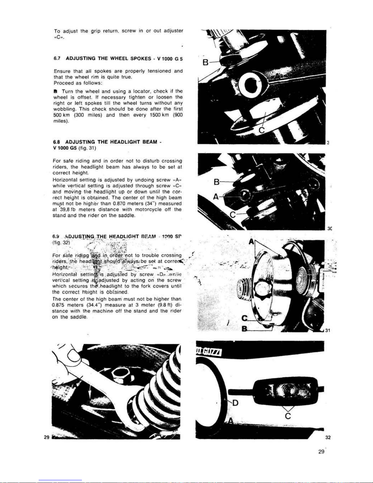
6.8
ADJUSTING
THE
HEADLIGHT
BEAM
-
IIloooG5
(tig. 31)
For safe
riding
and in
ord
er
not
to
dislurtl
crossing
ride~.
the
headligll\
tleam
Ilas always
to
tie set at
Carr
eel
height.
Hor
izontal
setting
is
adjusted
tly
undoing
screw
~A.
wh
ile
vertical
satting
is
adjusled Ihrough
screw
_C _
and
movi
ng
!luj h!!adlig
ht
up
or
down
until
the
cor
-
reel
height
is
otltained, The
cenler
01
the
Iligh
!>eam
mU
,sl
nOI
tie
hig~,er
Ihan
0.
870
meters (34"') measured
at
~9,e
Itl
meters
distance
with
motorcycle
ott the
stand
ano
Ihe
rider
on
the saddle.
8.&
.~
DJUSTING
..
THE
HEADLIGHT
nF.M.~
·
1:1')0
sr
(/ig.3il
•
:
':':'
:";~
"~ "~!;;
: ~,.
,
. '
-,
.' .. :,';:.
~
:.
~
..
Fo~
aa!e
.fi~!,9~
. i~,
orll,t!(.~~
\0
trouble
crossing
riden. ,ll)e
head'I\f!i
"t;~f>sl
Il!d!irT~ay~tle
sci
al
corre<'
'
~ighb,
:'.
r::~t~
.· .;~h~
~-:;-:·
· ·-"'~
_ .
HQrizonlal
setlin~.:is.adj.us1ed
tly
screw
.0,.
_,,,r,',<!
vllr1:
cal
seUing
.
~~diusled
tly aCll
r>g
on
II>1l
scrllW
which
~ecures
ther.
headhghl
10
Ihe
fork
covers
until
Ihe
correct
ht:rght is Obtained
rhe
center
or
lhe
high
beam
must not
bll
higher
than
0.
87$
meters (34.4" ) measure
at 3 meter
(9.8
II)
di.
stance
with the
machine
orr
Ihe
stand and the r
ider
on
1he
saddle
.
,
...
33
30
6.
10 ROCKER
CLEARANCE
(fig. 33)
Aller 1M lirst
500·
1000
~m
(3-
600
m!!<'!s) and lal'3'
On
every
3000
km (ab!. 2000 mi
les) or
any time valve r.pe-
ratoon
is
too
nOISy, CI'leCk
the
rocke,
clearance
.
Do
tllis adjustment
On a cold
engin
e with pi
ston
al
TOC
al
the end
or
Ihe
compression
stroke
(valves
fully
closed)
.
Ailer
removing
the
rocker
cover
. ope.ale as 101i0ws:
•
Unscrew
nUl . A
.,
• Screw in or out
adjuster
screw ·B-
unlll
the fOllo-
wing
clearance
is
oblained
:
0.
22
mm
(.0085")
for
both
the
inlet and exhaust valve.
Do
Ihis
Operal l
O"
using feeler gauge · C-,
II the
clearance
05
too
mUCh. the
re
will
be noisy valve
operation,
if
100
liltl
e.
the
valves
do
not
close
fully
caUSing inconveniences sueI'! as;
•
•
•
Loss
01
compression.
Overheating
01
engine
.
Burning
01
valves.
6.
11
ADJUSTING THE ODUBL
,E CONTACT
BREAKER
(lig. 30')
Ri
ghi cylind
e! :'ed
uble,
RDlate the
camshafl
'ill
Ihe POinlS
a'e
,n
lhe"
fully
Dpen pDSition.
Allhis
siage, inlroduce
Ine
I.Ilade
Of
lee
Ie'
gauge
_A·
be,...een
the
pDinlS
checking
Ihat
the
openi
ng
is
~",'
reCI
I.
e. 0.37.() 4
3mm (.014-.016-,.
In
case
Illis
distance
is
not
as
p,esctibed,
slaCken
screw~
.
C.
and .
0.
and
move
the fix
ed
po,nl
pla
le
-E-
acting
on
groove
. F. ,
10
the
"ght
o. lell
l,lI
the
cOrrect
diSlance
is Dbtai
ned
. .:.
...
Lell
cylinder
(g.een ca:Jle)
Procee~
U fDr I
he
rigl>t
cylinder except
that
,I
it
is
necessa.y
1(.
adjust
t
ht
poin!s
dislance, sCrews
.
G·
and . H.
a.e
tD
l.Ie
10DSened,
moving
Ihe fixed
con-
laet
plaia
. L_ in
9roove
·M.
unli1
Ihe
eOffecl
di-
stance
is
oblained
.
I
6.12
MAINTENANCE
(fig. 34)
Eve
....
3000 km (1800 miles).
Ihe
cam
felt
plale s
hould
be
lightly
moistened
with
a few
drops
of
all.
I
nspeelion
Proceed
as
IDIIDW5
:
•
RemDve Ihe
conlaet
breaker
cover
aUer undDi
ng
its
securing
screws
.
• II
contacts
· A_ and · 8 _ are
dirty
or
greasy. cl
ean
lnem wilh a pelrol
mDistened
tag
II III any
way da·
maged. 'ep
laee
them
.
•
Check
poin
ts gap
of
breaker .110
. \
flght
cylinder
red
cable) and
brea~et
-6 . (1
1.'11 cyli
nder· green ca'
ble)
wh,ch
should
be
0.37-
043
mm 1.014- 016
")
6.
13
CLEANING
THE WINDSHIELO
Any
type
soap. cleansing
. agen!. po li
sn
or
polish
ing
wax
normally
used
10
clean
plaslic
Or
glass materials
can
be
utill~ed
.
However.
lhe
following
precautions
should
tle taken:
•
Never
wash
Or
clean
the
w;ndshield
when
the
external
lemperature
is
very high
Of
altar
exposure
10
Iha Sun.
•
Under
no
circumstanc
es. solv
ents
. Iyes.
Or similar
prOducts
should
be used.
•
00
nOI
use
liquIdS
conlalning
abrasive
m'lleriaiS.
pumice
powder. emery
paper.
scrapers
or
$uchli~e.
• BefOre
polishing
ensure
that all
dust
and
impur
i-
ties are
remoV<!d.
•
Ught
scratches
can
be
smoolhed
OUI with
lighl
polish.
•
fresh
paint
01
sealing
compounds.
when
sllll
wet.
can
easi ly be
removed
by
lightly
rubbing
011
with
iso
·
propyli<:; alCOhol.
soluble
mineral
Oil.
bulyl
or
cello·
solva (Nevar usa
melnylic
IIlcohol)
.
•
Use a
solt
sponge
Or
clOlh.
chamois
leather
or
COtlOnwool.
rubbing
lightly
.
•
Never
use
paper
10wels.
synlhelic
lib
ar
clolhes
w~i<:;h
may
scralch
tha
windshield
surlaca
.
Vigorous
rubbing
or
SOlvents
...
,11
n01
remove
deep
scratChes
or
nicks.
31
 Loading...