

Page 1

Motic Images Plus 3.0 ML Software
Windows OS User Manual
Page 2

Introduction 05
Menus and tools 05
File 06
New 06
Open 07
Save 07
Save as 07
Export 07
Capture 08
Image Comparison 08
Album 09
Folder 09
Amalgamation 10
Report 11
Report tool bar 12
New Page 12
Load 12
Save 12
Print Current Page 13
Print 13
Edit 13
Text 13
Color 14
Font 14
Settings 14
Capture 14
Audio 15
Exit 15
Edit 15
Rectangle Marquee 16
Circle Marquee 16
Ellipse Marquee 16
Polygon Marquee 16
Irregular Marquee 16
CONTENTS (Linked)
Motic Images Plus 3.0 ML Software | Windows OS User Manual
Page 3

Image 17
Brightness/Contrast 17
Hue/Saturation 18
RGB 18
Mirror 18
Vertical 19
Rotate 90° 19
Gray Scale 19
Invert 19
Image Size 19
Filter 19
User defined Filter 20
Measure 21
Line 21
Rectangle 21
Circle 21
Circle (3 points) 21
Arc 22
Ellipse 22
Polygon 22
Freehand 22
Freehand Line 22
Angle 22
Parallel 22
Marker 22
Auto Calculation 23
Calibration Wizard 24
Calibration Table 25
Language 25
Style 25
View 25
Help 26
About 26
Help 26
Page 4

Control Panel 26
Edit 27
Text 27
Paint 27
Audio 28
Measure 30
Magnifier 32
Preview Window 33
How to use the Popup Menus... 33
...in the Image window 33
...in the Album window 35
Calibration... 36
...with Calibration Circle 36
...with Scale Cross 37
...with Scale Line 38
Page 5
Motic Images Plus 3.0 ML is multi-language software offered by Motic China Group Co., Ltd. It is
especially designed to adjust interactively a live image supplied by a Motic USB camera, capture the
optimized image and perform further analyzing and measuring tasks.
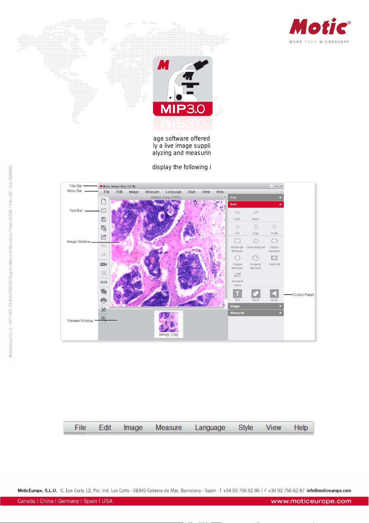
Opening Motic Images Plus 3.0 ML will display the following interface:
The interface is composed of the Title Bar, Menu Bar, Tool Bar, Image Window, Control Panel and
Preview Window.
Menus and tools
The Menu Bar includes the functions File, Edit, Image, Measure, Language, Style, View and Help.
Click the buttons on the Menu Bar to display the corresponding tools.
Page 6
Menus and tools / File
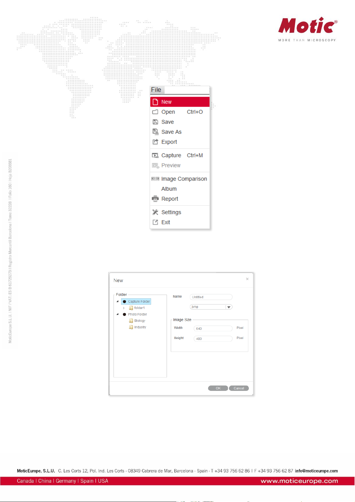
File includes the following commands: New, Open,Save, Save As, Export, Capture, Preview, Image
Comparison, Album, Report, Settings and Exit. Shown below is the corresponding tool bar:
Menus and tools / File / New
The New command enables to create a new image file:
Select the format of the image file (jpg; bmp; tiff; png) and the file name. “png” is a proprietary Motic
format which can only be opened with Motic Images Software. Define the image size. Capture Folder
defines the location where the new image file should be saved.
Page 7
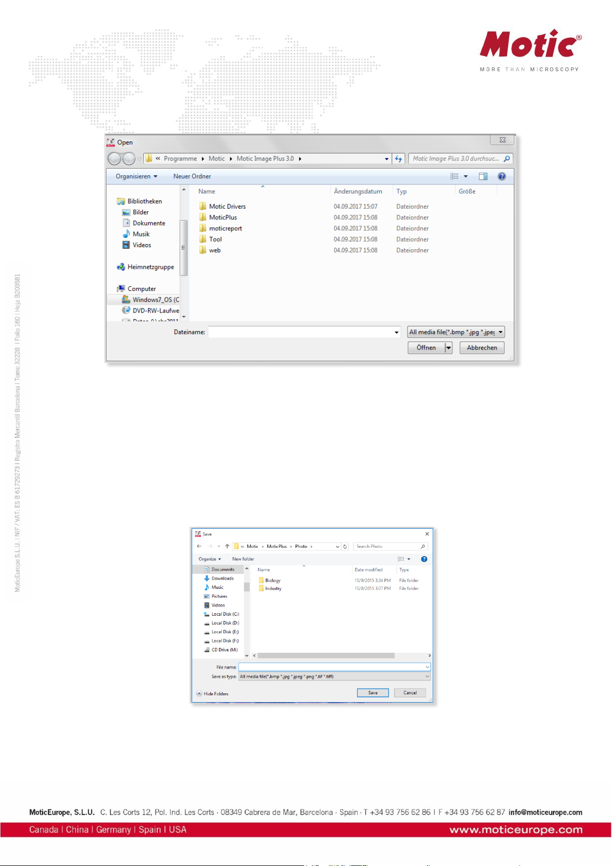
Menus and tools / File / Open
The Open command allows users to open already existing image files:
Menus and tools / File / Save
The Save command allows to save the current image in the selected format.
Menus and tools / File / Save As
The Save As command provides another method for saving the current image. The following dialog box
will display allowing users to save the image to a different destination and in a different format than its
source.
Menus and tools / File / Export
Export saves the current image in a selected path.
Page 8

Menus and tools / File / Capture
Selecting the Capture command will bring up the Motic Live Imaging Module to handle images seen
through the microscope connected to the computer.
Note: The capture device can be preset using the Setting command of the File menu or the Setting
button on the File Toolbar:
Menus and tools / File / Image Comparison
The Image Comparison command opens a window composed of two frames for a side-by-side
comparison of two images.
Page 9
There are four ways to load the images for comparison:
1. Double click on either frame to load images from the local disk.
2. Right click within either frame and select Load Image from the shortcut menu to load the desired
images for comparison.
3. Images may also be dragged into either of the frames directly from the Album or Preview window.
4. Click “Load Image” button to import the selected image.
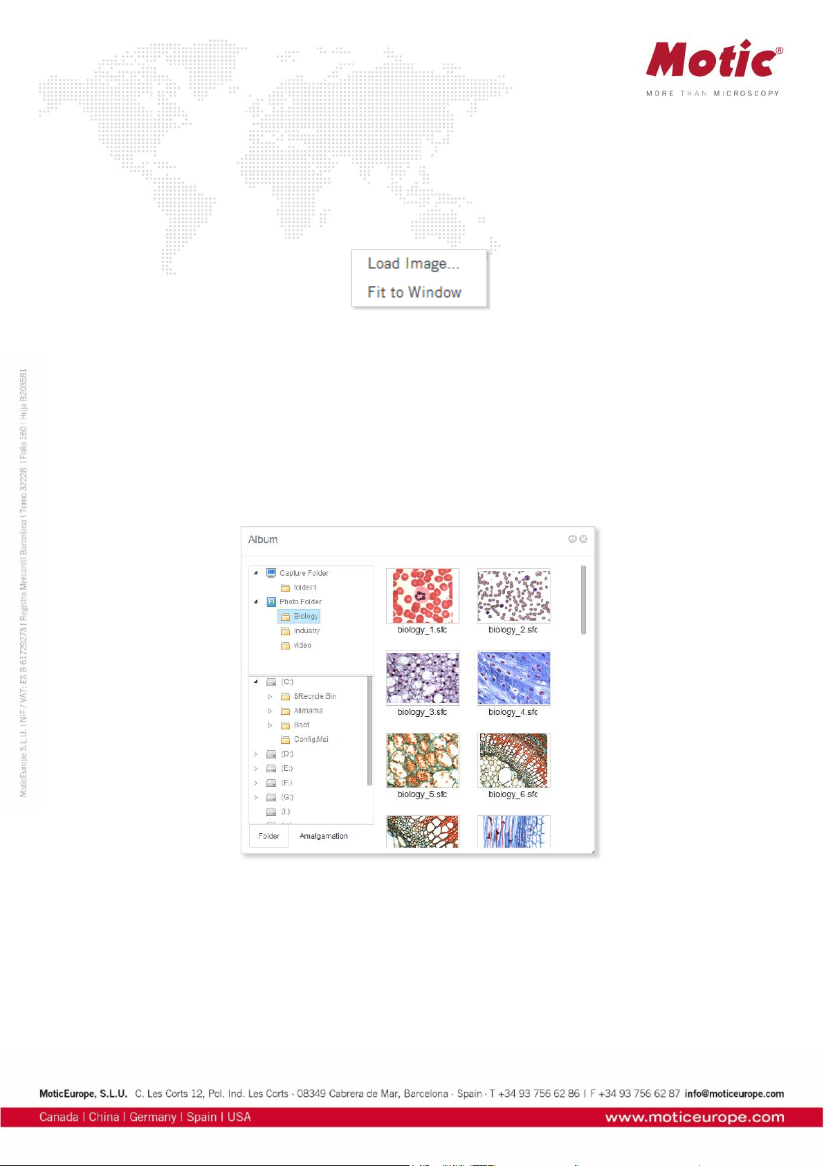
Menus and tools / File / Album
The Album command allows to open already existing images from their thumbnails. It also opens the
general WINDOWS explorer. Click the Album button to bring up the following window:
Menus and tools / File / Album / Folder
The upper column displays the Motic Images Plus 3.0 ML image folders, the images captured will be
saved here. The contents of an Image Folders on the left will be shown in a thumbnail display on the
right. Double click on a thumbnail selects a file for single image display; “Drag and Drop” from thumbnail
to Preview window is also possible. With Set default capture folder a predefined path for image storage
can be set.
Page 10

Menus and tools / File / Album / Amalgamation
Amalgamation is a helpful tool for image overlay, especially for multiple stained samples in fluorescence.
Click the Amalgamation tab to display the following interface:
Select the desired images and drag them into the Amalgamation panel. Click the Amalgamation button
and a popup menu listing various amalgamation calculations will be displayed.
Page 11
Select an amalgamation method and a dialog box will display to confirm the name of the resulting image.
Check the different options to find the best possible amalgamation result. The overlay will be saved in the
format “combination_1.”
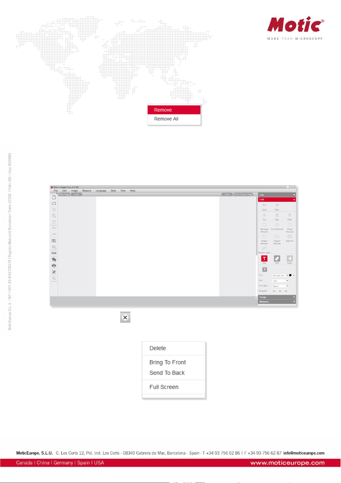
Clicking the Remove/Remove All buttons will remove selected image.
Users can also remove an image in the Amalgamation panel by left click for selecting it; then clicking the
right mouse button to bring up the following popup menu:
Menus and tools / File / Report
The Report function is an integral part of Motic Images Plus 3.0 Software. Users are able to load images
and add text fields for printing or export purposes. A report will be saved under proprietary format
moticreport.mwp.
To close the report button click located in the top right corner.
Click the right mouse button in the Motic Report window to bring up the following popup menu:
Page 12

Menus and tools / File / Report / Report Tool Bar
The Report Tool Bar is located at the top of the Report window and displays as follows:
Menus and tools / File / Report / Report tool Bar / New Page
The New Page button creates a new report page.
Menus and tools / File / Report / Report tool Bar / Load
The Load button brings up the following dialog box from which an existing report may be opened.
Menus and tools / File / Report / Report tool Bar / Save
The Save button brings up the Save As dialog box which allows users to save the report documents as
*.mwp format files.
Page 13

Menus and tools / File / Report / Report tool Bar / Print Current Page
The Print Current Page button enables users to preview the current report.
Menus and tools / File / Report / Report tool Bar / Print Setting
The Print Setting button brings up the Print dialog box.
Menus and tools / File / Report / Edit / Text
Click the Text button and move the cursor to the location on the report where the text is to be displayed, click the left mouse button and begin typing.
Page 14

Menus and tools / File / Report / Edit / Text / Color
The Color button brings up the Color Palette through which users are able to select a text color.
Menus and tools / File / Report / Edit / Text / Font
The Font button brings up the Font dialog box.
Menus and tools / File / Settings
The Settings command provides access to the parameter of Still Image capture, image sequences and
Audio options.
Menus and tools / File / Settings / Capture
Click the Capture tab to display the capture settings. Here, define the file name, image size, the
frequency and the maximum number of images to be captured automatically. To choose the Using
current date and time as file names option, click the respective check box.
Click OK to confirm.
Page 15
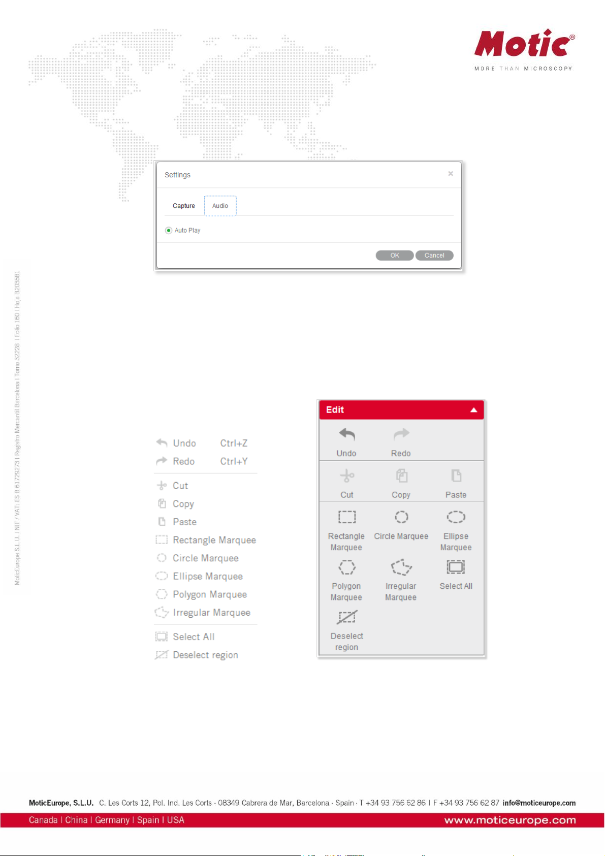
Menus and tools / File / Settings / Audio
Click the check box to the left of the Auto Play option and the music selected in the Playlist of the Control
Panel will play automatically each time Motic Images Plus 3.0 ML is opened. Click OK to confirm.
Menus and tools / File / Exit
The Exit command closes the program after prompting users to save any unsaved files.
Menus and tools / Edit
The Edit Menu allows to define selected areas for further handling. The corresponding tool bar functions
are equivalent:
Page 16

Rectangle Marquee
A Rectangle Marquee will be defined by clicking and dragging the left mouse button.
To move the selected rectangular region, place the mouse pointer on the side of the figure, and then click
and drag when the cross pointer appears.To change the size of the selected region, place the mouse
pointer on a corner of the rectangle, and then click and drag the mouse when the hand pointer appears.
Circle Marquee
The Circle Marquee will be defined by clicking the left mouse button to define the center and to drag for
size variation.To move the circle, place the mouse pointer at the center, then click and drag the mouse
when the cross pointer appears. To change the size of the selected region, place the mouse pointer at
the extreme point of the radius, then click and drag the mouse when the hand pointer appears.
Ellipse Marquee
The Ellipse Marquee is defined like a circle. To move the selected elliptical region, place the mouse
pointer at the center of the ellipse, then click and drag the mouse when the cross pointer appears.
To change the size of the selected region, place the mouse pointer at the extreme point of the major or
minor half axis, then click and drag the mouse when the hand pointer appears.
Polygon Marquee
A Polygon Marquee is defined by clicking and dragging the left mouse button.To move the polygon,
place the mouse pointer on the side of the polygon, then click and drag the mouse when the cross pointer
appears. To change the size of the selected region, place the mouse pointer on a corner of the polygon,
then click and drag the mouse when the hand pointer appears.
Irregular Marquee
With the Irregular Marquee command, users are able to define an irregular region by clicking and
dragging the mouse. The selected irregular region may be moved using the drag-and-drop method when
the cross pointer appears.
All selected areas can be deleted by or right mouse button: Deselect region
Page 17
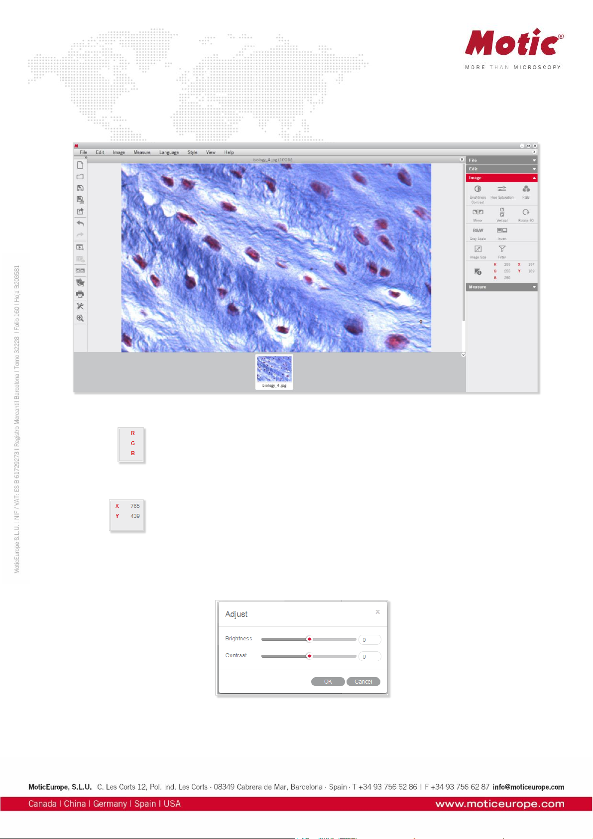
Menus and tools / Image
The Image Menu includes the all commands for a post-capture image correction. The corresponding tool
bar functions are shown below:
The RGB box displays the color information at the point of the cursor's current location.
The XY box displays the XY coordinates of the cursor's current location.
Menus and tools / Image / Brightness/Contrast
The Brightness/Contrast command displays separate sliders for both parameters.
The Default values are both set to “0”. For brightness, the value range is -255 to +255; for contrast it is
-127 to +127.
Page 18

Menus and tools / Image / Hue/Saturation
Select the Hue/Saturation command to bring up the following window:
Hue values can be varied from -360 to +360; the default value is “0”. Saturation range is from -100 to
+100; default value is “0”.
Menus and tools / Image / RGB
Select the RGB command to bring up the following window:
The three sliders are used to adjust the red, green and blue color channels of the active image. The value
range always is from -100 to +100 with default value “0”.
Menus and tools / Image / Mirror
The Mirror command mirrors the current image horizontally.
Page 19
Menus and tools / Image / Vertical
The Vertical command mirrors the current image vertically.
Menus and tools / Image / Rotate 90
The Rotate 90 command rotates the current image clockwise by 90 degrees.
Menus and tools / Image / Gray Scale
The Gray Scale command converts the current image into a B/W image.
Menus and tools / Image / Invert
The Invert command inverts the current image colors.
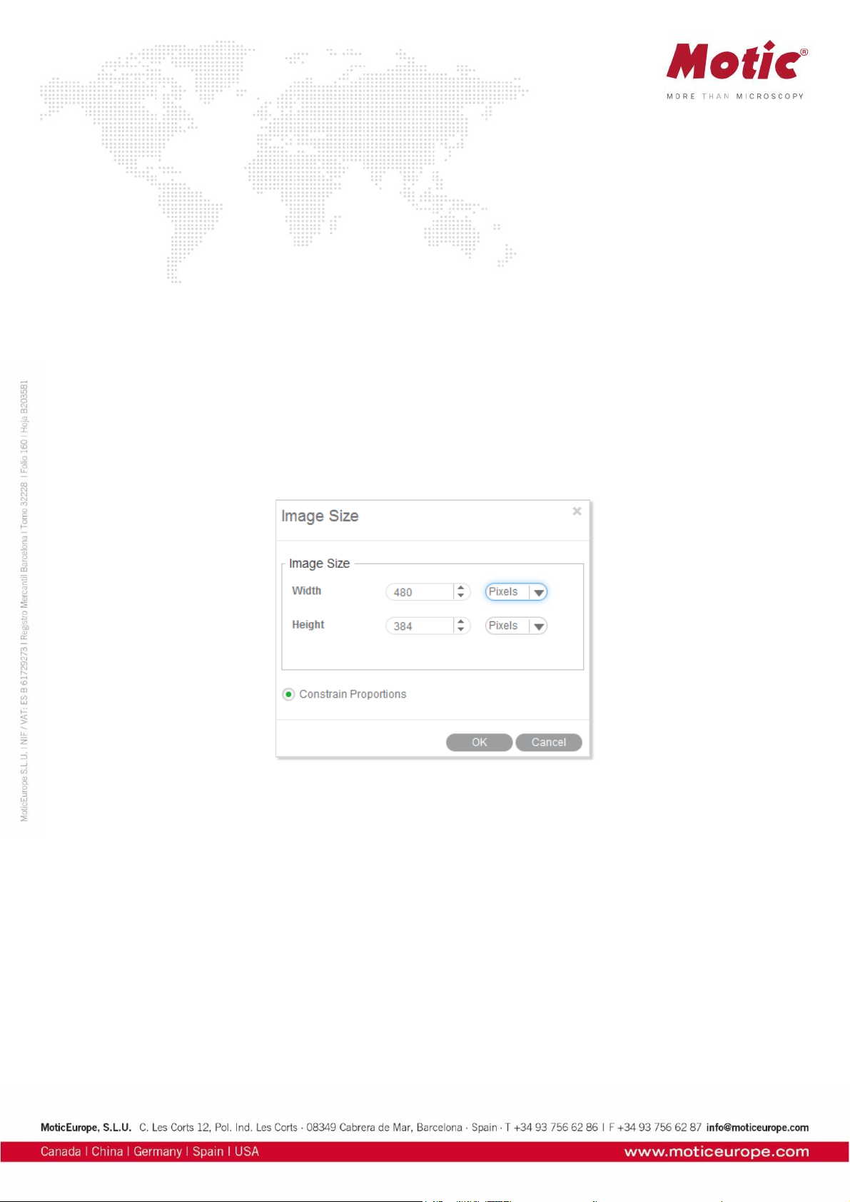
Menus and tools / Image / Image Size
Image Size brings up the Image Size dialog box. The units may be "Pixel" or "Percent".
Select the Constrain Proportions checkbox to keep the image proportions even though the image size
is changed. If Width or Height values are changed manually, the corresponding value will automatically
be adjusted to keep the image proportions.
Menus and tools / Image / Filter
The Filter command allows to apply several filters on the saved image.
Page 20
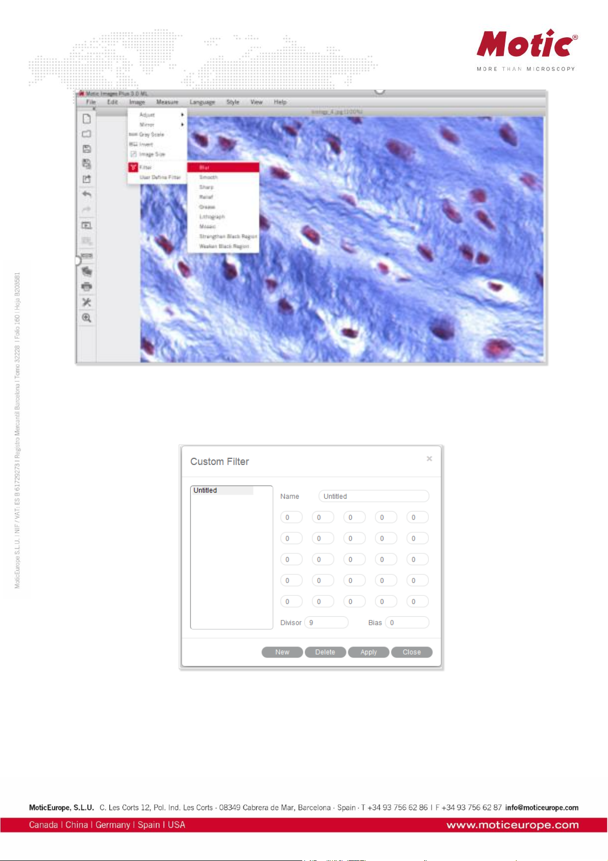
Menus and tools / Image / User defined Filter
The User Define Filter command allows the individual configuration of a filter.
To define a new filter, click "New" and enter the name of the new filter. Enter values into the blanks to
create a filter matrix with divisor and bias.
To open an existing filter, select an item from the list and click "Apply".
Page 21
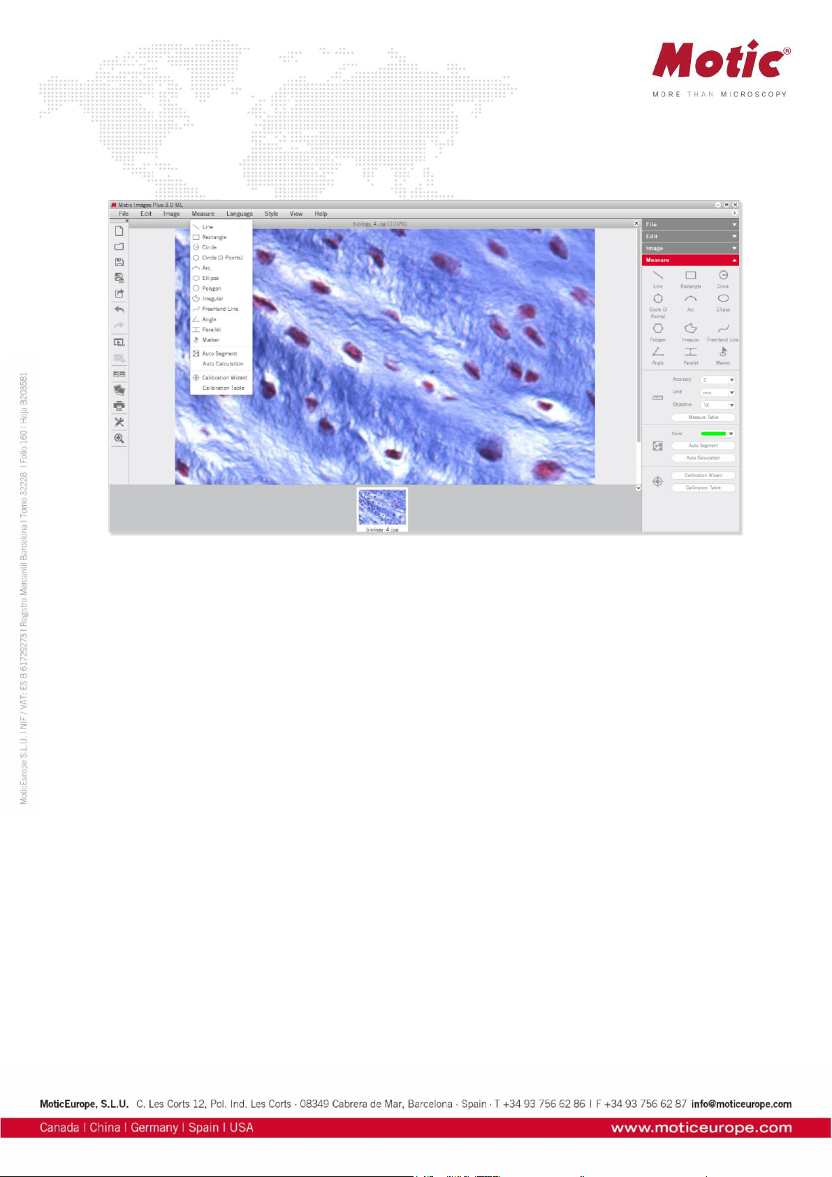
Menus and tools / Measure
The Measure Menu includes the commands for measuring several geometrical figures as well as the
quantification tools Auto Segment, Auto Calculation, Calibration Wizard and Calibration Table.
Line
Line measures distances, diameter etc. Click the left mouse button and drag a line. The result is
displayed immediately.
Place the mouse pointer at the extreme point of the line (arrow → hand pointer) and change the length
interactively. Place the mouse pointer on the line, then click and drag the mouse when the cross pointer
appears to move the line.
Rectangle
The Rectangle command measures the width, height, area and perimeter of rectangles. Click and drag
the left mouse button on the image to create a rectangle.
Place the mouse pointer at the vertex of the rectangle, then click and drag the mouse when the hand
pointer appears to change the size of the rectangle. Place the pointer on an edge of the rectangle, then
click and drag the mouse when the cross pointer appears to move the rectangle.
Circle
The Circle command measures the radius, area and perimeter of circles.
Place the mouse pointer at the extreme point of the radius, then click and drag the mouse when the hand
pointer appears to change the size of the circle. Place the mouse pointer on the center of the circle, then
click and drag the mouse when the cross pointer appears to move the circle.
Circle (3 points)
The Circle (3 points) command measures the radius, area and perimeter of circles. Define a circle by 3
points. Place the mouse pointer on any of the three points on the circle, then click and drag the mouse
when the hand pointer appears to change the size of the circle. Place the mouse pointer on the circle,
then click and drag the mouse when the cross pointer appears to move the circle.
Page 22

Arc
The Arc command allows users to measure the radius, perimeter, angle and arc length.
Click and drag the mouse to create an arc with 3 points. Place the mouse pointer at one red point of the
arc, then click and drag the mouse (arrow → hand pointer) to change the shape of the arc. Place the
mouse pointer on the arc, then click and drag the mouse (arrow → crosspointer) to move the arc.
Ellipse
The Ellipse command measures the major half axis, minor half axis, area and perimeter.
Place the mouse pointer on the extreme point of the major or minor half axis, then click and drag the
mouse when the hand pointer appears to change the size and shape of the ellipse. Place the mouse
pointer on the center of the ellipse, then click and drag the mouse when the cross pointer appears to
move the ellipse.
Polygon
The Polygon command measures the area and perimeter.
To complete a polygon, double click the left mouse button on the end point.
Place the mouse pointer on any edge of the polygon, then click and drag the mouse when the hand
pointer appears to change the size of the polygon. Place the mouse pointer on any point of the polygon,
then click and drag the mouse when the cross pointer appears to move the polygon.
Irregular
The Irregular command measures the area and perimeter of irregular figures. Click and drag the left
mouse button on the image to drawn an irregular image, release the button to complete the shape
automatically. Click and drag the mouse when the cross pointer appears to move the irregular figure.
Freehand line
This Freehand Line command allows users to measure the length of free lines.
Place the mouse pointer on the free line, then click and drag the mouse when the cross pointer appears
to move the free line.
Angle
3 points set by the left mouse button will define an Angle. Depending on the drawing, the internal or
external angle is measure. Place the mouse pointer at the end of the angle leg, then click and drag the
mouse (arrow → hand pointer) to change the angle. Place the mouse pointer on any point of the angle,
then click and drag the mouse (arrow → crosspointer) to move the angle.
Parallel
Parallel allows to measure the distance between 2 parallel lines. Draw the first line and end it by mouse
click. Moving the mouse creates a parallel line. Both lines can be moved by clicking the grey middle
marking (arrow →cross).
Marker
Using Marker allows to highlight defined points of interest. The x/y coordinates are displayed.
Page 23
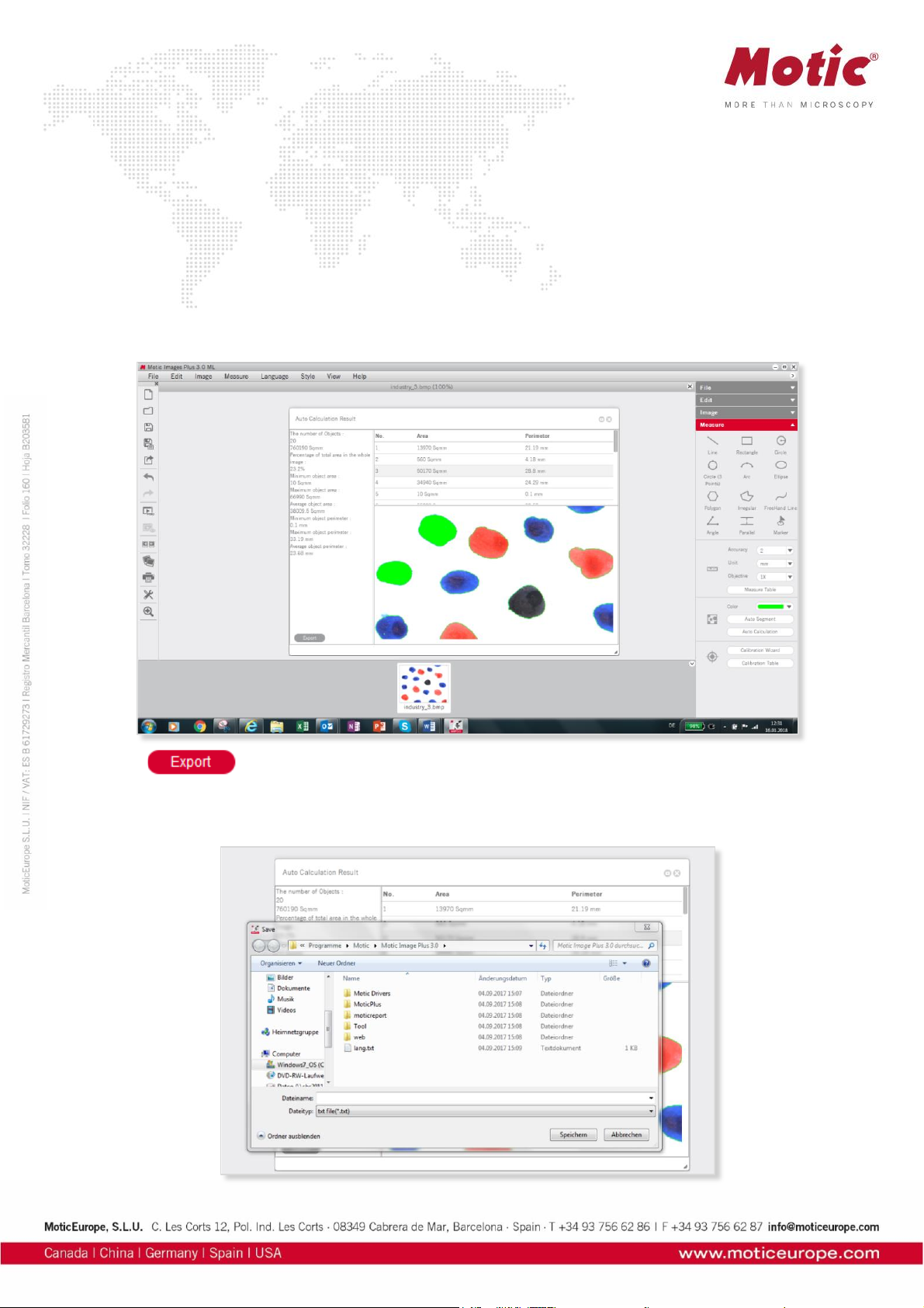
Auto Calculation
The Auto Calculation command provides detailed data of the objects segmented from the image.
The Auto Calculation Result window will then be displayed, such as number of objects, total area,
percentage of total area, minimum object area, maximum object area, average object area, minimum
object perimeter, maximum object perimeter, average object perimeter and the serial number, area and
perimeter of respective objects.
To access the data of a certain object, click on the object in the image window and the data for that object
will be highlighted.
Click on the data of the desired object(s) and the corresponding object(s) will flicker in the image window.
Click and drag on a particular data item to change its location in the list of results.
Click to bring up the Save As dialogue for export the calculation results as a Text file (*.txt)
or CVS file (*.cvs).
Page 24
Calibration Wizard
A correct calibration is essential for any kind of measurement, for correct scale bars and grid dimensions.
The Calibration with Calibration Circle is based on the dot patterns metallized on the glass calibration
slide provided with Motic cameras. The calibration with Scale Cross and Scale Line are intended to be
used in case the smallest dot on the calibration slide is even too large to be captured completely by an
image.
Select the Calibration Wizard command to bring up the following interface:
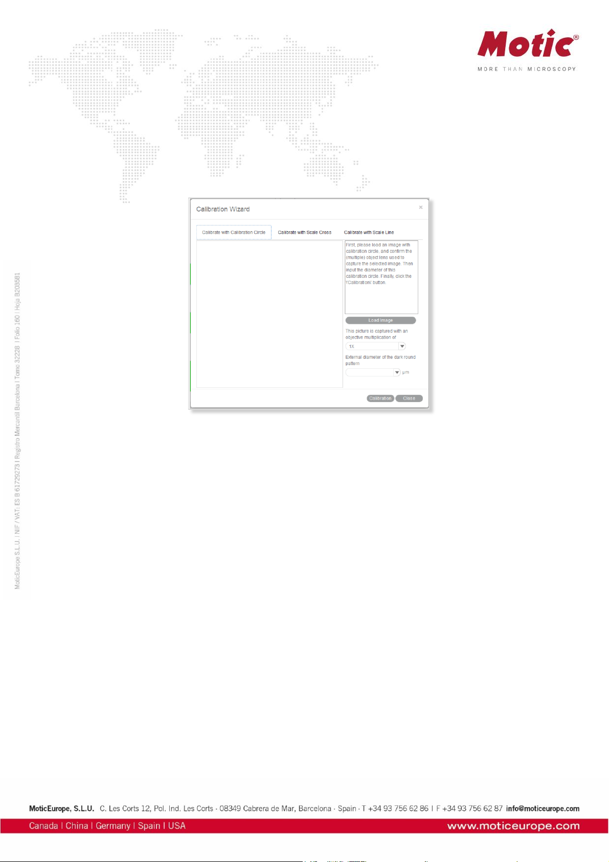
Calibration with Calibration Circle
To calibrate with a calibration circle, select the respective Calibration Wizard tab. Click Load Image to
select a calibration circle from your image database. Confirm the objective lens used to capture the
selected image and input the diameter of the calibration circle. Click the Calibration button to open a new
dialogue box. Check the x/y-axis values; they should only differ by one decimal place. Activate the
“Scale” option (if not active by Default setting). This function will adjust e.g. the scale bar depending on
the display mode (resolution, Full screen). Enter a New Sign Name to refind your calibration easily within
the calibration table. Next, click the Save button to finish calibration.
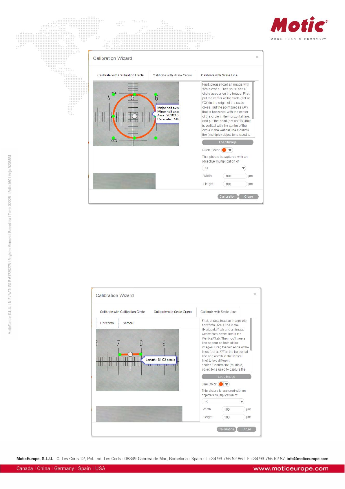
Calibration with Scale Cross
To calibrate with a scale cross, select the respective Calibration Wizard tab.
Click Load Image button to select a scale cross from your image database.
When the image is loaded, a circle will appear on the scale cross. If desired, choose a different color.
Place the center of the circle (set as "O") exactly into the center of the scale cross. Next, take a reddish
marked point ("A") in the X-direction and drag it on the horizontal line to a certain scale division, then
perform identically in Y-direction ("B"). The magnifier window under the image window may help to place
the points accurately.
Confirm the objective lens used to capture the selected image and input the actual length of "OA" in the
"Width" bar and the actual length of "OB" in the "Height" bar. Take note about the scaling of the scale bar.
Click the Calibration button to open a new dialogue box. Continue as under Calibration with
Calibration Circle.
Page 25
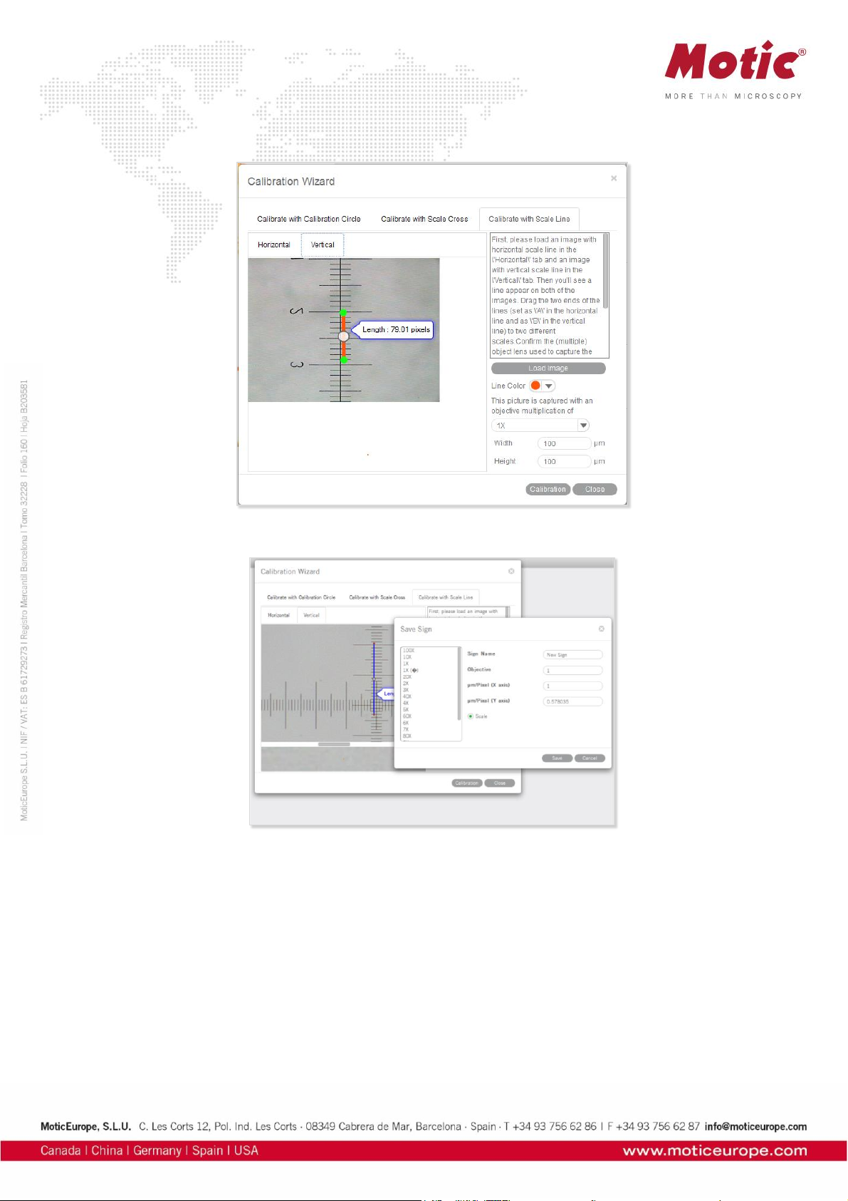
Calibration with Scale Line
To calibrate with scale line, select the respective Calibration Wizard. This wizard performs calibration in
X- and Y-direction separately, using the same image type: a scale cross.
Click Load Image to open the image of a scale cross. Click the Horizontal tab to activate a horizontal
line overlaying the scale cross. If desired, choose a different color. Extend the line by dragging with the
left mouse button to a defined scale division. Confirm the objective lens used to capture the selected
image and input the actual length.
Please repeat this procedure for Y-direction (Vertical tab). Click the Calibration button to continue as in
Calibration with Calibration Circle.
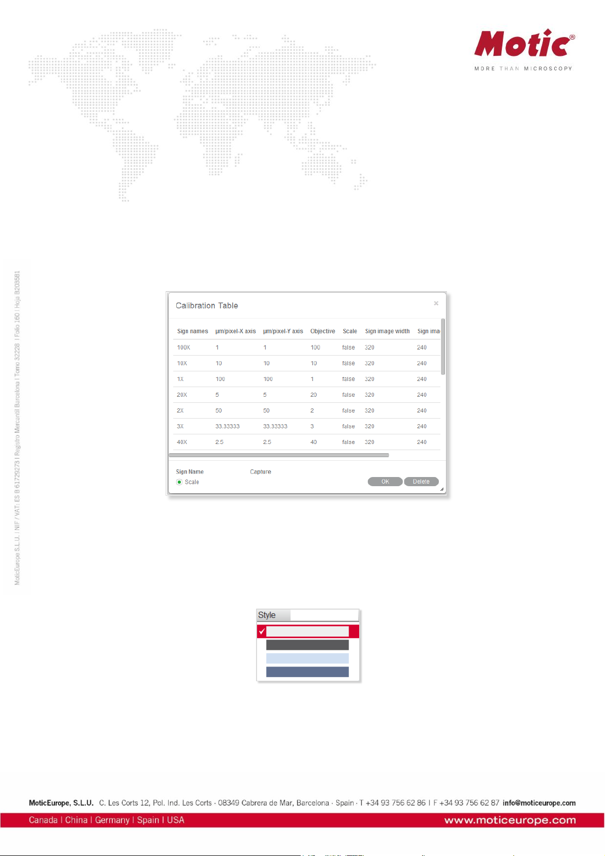
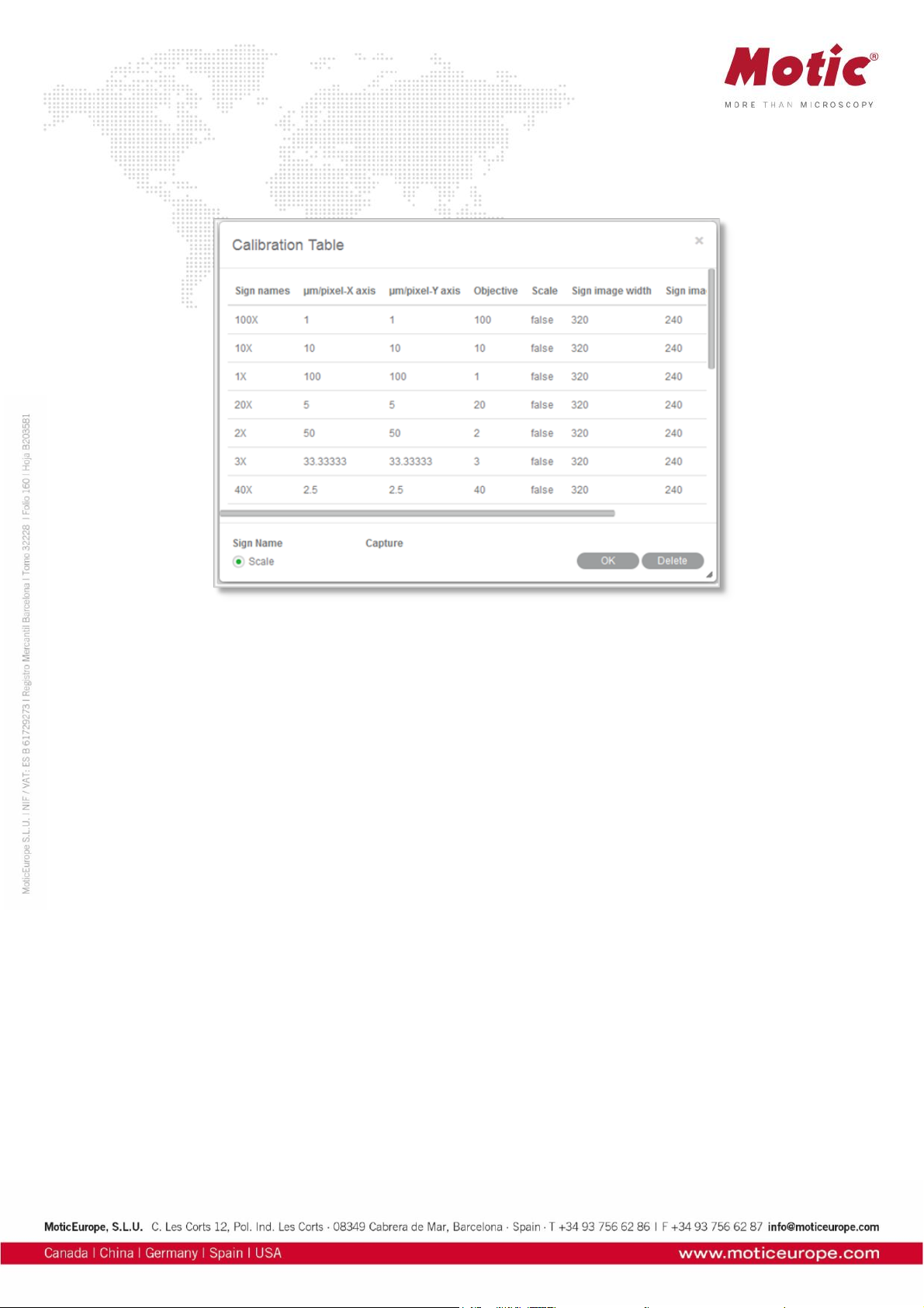
Calibration Table
The Calibration Table shows all calibration data saved for later usage.
If the Scale check box is selected, the measurement results will stay correct, no matter which display
format/resolution is used.
Menus and tools / Language
Select a language from the drop down list.
Menus and tools / Style
4 color styles are provided, click “Style” button and select one of them to switch the interface style.
Menus and tools / View
Displays the panel status. When you select it, the panel will display in the software interface.
Page 26

Menus and tools / Image / Help
The Help menu has two commands:
Help
Provide detailed instructions on how to use the program.
About
Display the program's copyright and version information.
Control Panel
When an image is opened in Motic Images Plus 3.0 ML, the following Control Panel will display inside the Edit Tab.
Page 27
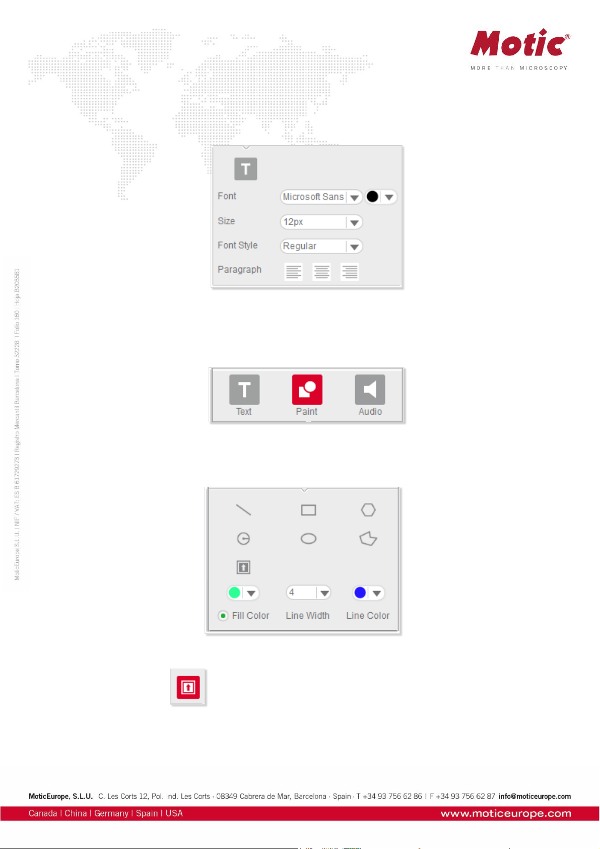
Control Panel / Edit / Text
The Control Panel is composed of the following tabs: Text, Paint, Measure, and Audio.
Click Text in the Control Panel to display the text editing options.
Control Panel / Edit / Paint
The Paint tab in the Edit Control Panel allows to draw geometrical figures.
The following figures can be drawn: line, rectangle, polygon, circle, ellipse, freehand. All figures can be
edited.
Click the Icon button to bring up a dialog box which provides a variety of icons to add to the
current image.
Page 28

Select a desired icon and click on a position of the image to place it.
Illumination will vary a shadow-effect representing the direction of an illumination.The slider under the
circles varies the illumination angle.
Click the Rotate 90 button to rotate the icon 90° clockwise.
Control Panel / Edit / Audio
Click the Audio tab to display the Audio control panel:
Play List brings up the Playlist window, to which external audio files can be added.
Page 29

Click the right mouse button in the window to display this popup menu:
To add music to the playlist, select the Add command to display the open dialog box:
Select the desired music files, click the Open button and the selected music will be added to the playlist.
If the Auto Play option in the Audio panel of the Setting dialog box has been selected, the music in the
playlist will be played automatically each time Motic Images Plus 3.0 ML is started.
To remove the music listed in the playlist, select the Remove All command from the popup menu.
The buttons refer to Start, Pause and Stop.
Clicking dedicates the audio file to an individual image file. Move the cursor onto the image and
click left to display the following box:
The buttons , and refer to Start, Pause and Stop. Click the Record button to display the
Record window with which users are able to record sound, music, etc.
Page 30

Click the button to bring up the Open dialog box from which users can open existing audio files.
Control Panel / Measure
Click the Measure tab to display the Measure control panel.
Page 31

From the Objective Lens drop down list, select the objective lens that was used to capture the current
image. The color of Auto Segment can be selected.
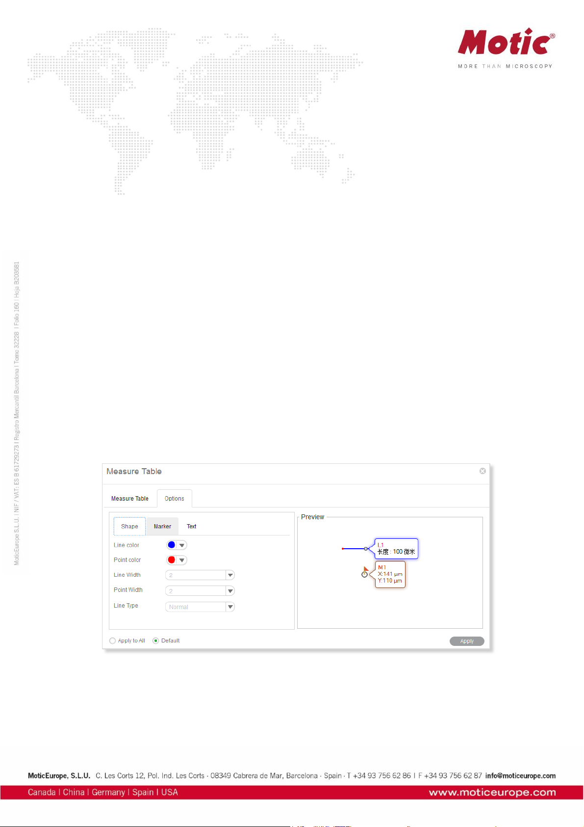
The Measure Table button opens the following window which is composed of two tabs, Measure Table
and Options. The Measure Table tab lists all measurement results.
To export the data in the Measure Table, click "Export" to bring up the following dialog box with which
users are able to save the data as *.txt or *.cvs files.
The Measure table can be edited as well:
Page 32
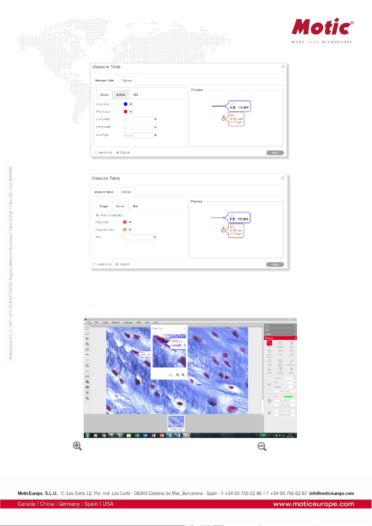
Toolbar / Magnifier
The Magnifier is a helpful tool especially for measurements. Start and end of a line, etc. can be precisely
defined.
Click the button to increase the magnification up to 800%.and click the button to reduce it.
Preview Window
Page 33
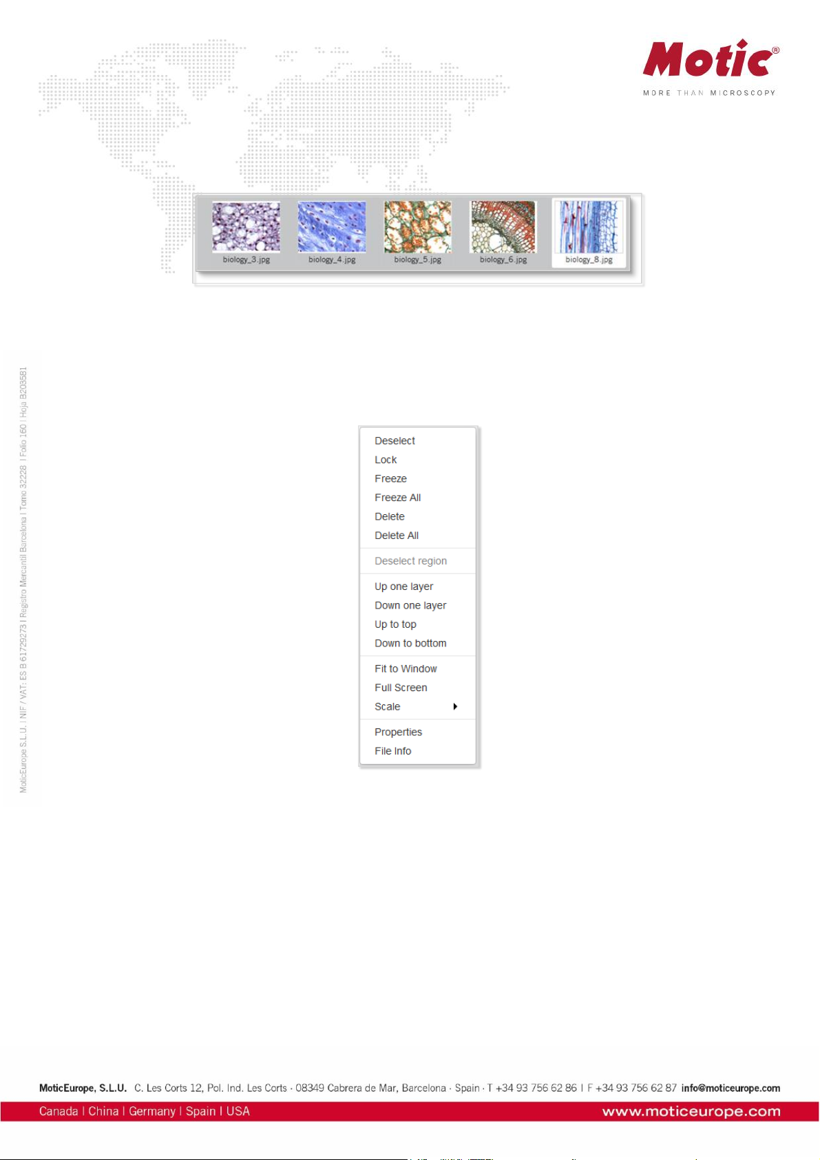
The Preview Window is located to the bottom of the image window.
It shows all images actually opened.
How to use the Popup Menus
How to use the Popup Menus.... / ...in the Image window
Click the right mouse button in the image window to display the following popup menu:
Deselect
This command deselects the selected objects.
Lock
This command locks the selected region(s) making it impossible to move it/them around.
Freeze
This command freezes the location and size of the selected figure and fixes it to the image.
Freeze All
This command freezes the location and size of all the figures and fixes them to the image.
Delete
This command deletes the selected region.
Delete All
Page 34
This command deletes all regions that have not been locked or frozen.
Deselect region
This command deselects the selected regions.
Up one layer
This command brings the selected region up one layer.
Down one layer
This command brings the selected item down one layer.
Up to top
This command brings the selected item to the top layer when there are several items on the image.
Down to bottom
This command brings the selected item to the bottom layer when there are several items on the image.
Fit to Window
This command resizes the image to fit into the current window.
Full Screen
This command brings the image window into full screen view.
Scale
This command resize the current image by scale.
Properties
This command brings up the properties dialogue to define the selected object's parameters.
File Info
Page 35
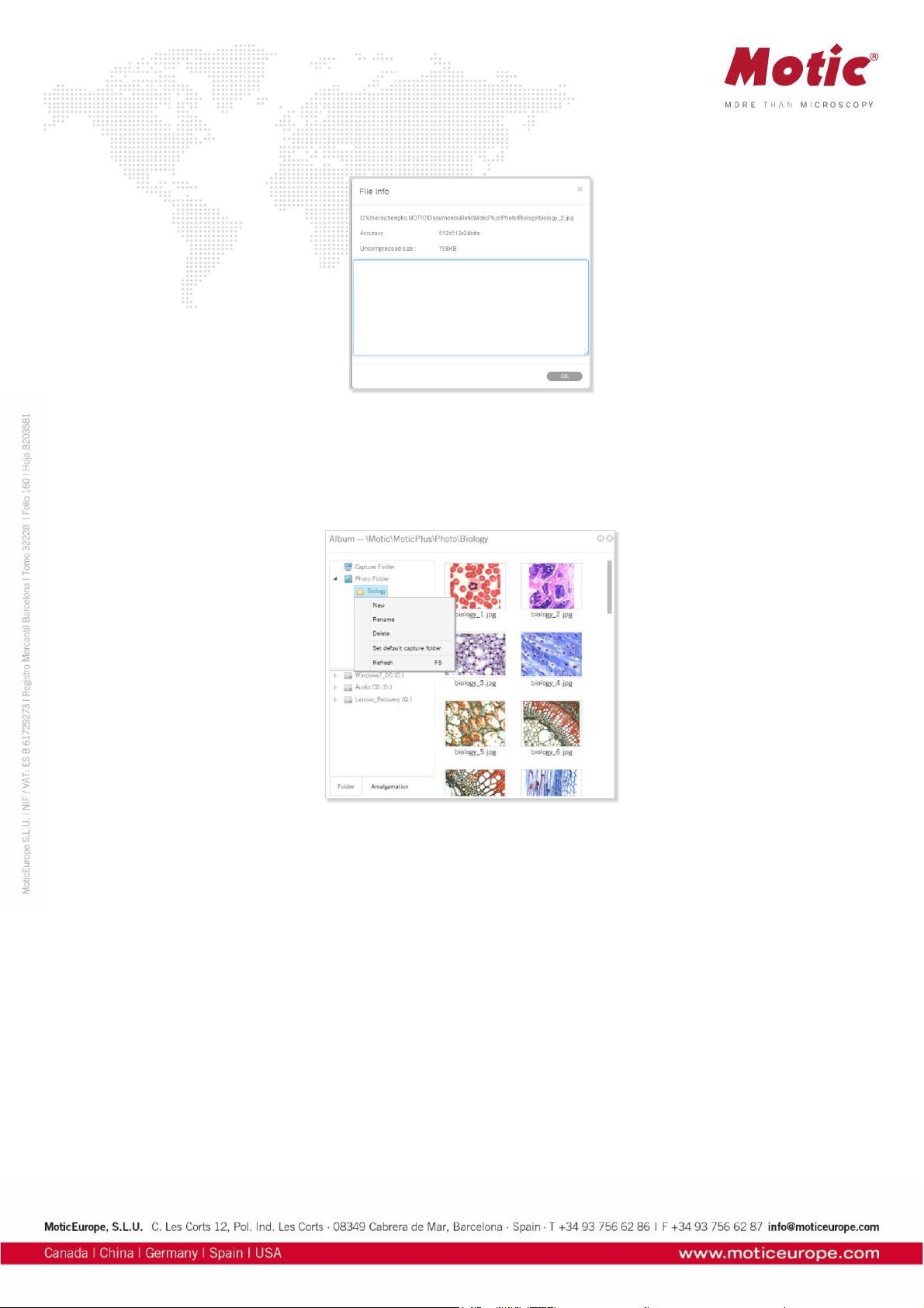
This command brings up the File Info dialog box which provides information about the current image.
How to use the Popup Menus... / ...in the Album window
Click the right mouse button in the upper column of the Folder panel to bring up the following popup
menu:
New
To add a sub-folder to the selected folder.
Rename
This command enables users to rename the selected folder.
Delete
This command enables users to delete the selected folder.
Set as default capture folder
This command enables users to set the selected folder as the default capture folder. Images captured
using this program will then be saved in the selected folder automatically.
Refresh (F5)
This command enables users to refresh the contents displayed in the upper column of the Folder panel.
Pressing the F5 key will refresh the contents as well.
Calibration
Any kind of measurement, scale bar or grid needs a precise calibration for a correct quantification.
Place the calibration slide (within the delivery package of your Moticam) into the raypath of the
microscope and focus one a calibration circle (in fact it’s a dot). Depending on the objective/camera
adapter/camera sensor combination, the correct dot has to be chosen. As all dots on the calibration slide
Page 36

are placed in one line, it is easy just to use the x-drive of the microscope stage to move from one dot to
another. Before taking a picture, note that the selected dot should be grabbed completely, at the same
time being be as large as possible in the image field. This will improve the precision of all measurements.
Click the Calibration button in the Measure tool bar to display the corresponding toolbar.
Calibrate... / ... with Calibration Circle
Select the Calibration Wizard command. Select a calibration method by selecting the corresponding tab.
Click the Load Image button to open an in image with a calibration circle to be selected for calibration.
Click the Open button to load the selected image.
Select the magnification of the objective used for taking this picture, enter the diameter of the calibration
dot (vacuum-metallized on the calibration slide) in the corresponding box. Click "Calibration” to continue.
Check the x/y-axis values; they should only differ one decimal place. If not, the illumination is
inappropriate.
Please note: The calibration slide is intended to work with transmitted light. In incident light, the dot
appears bright. In this case please invert the image before loading for calibration.
Page 37
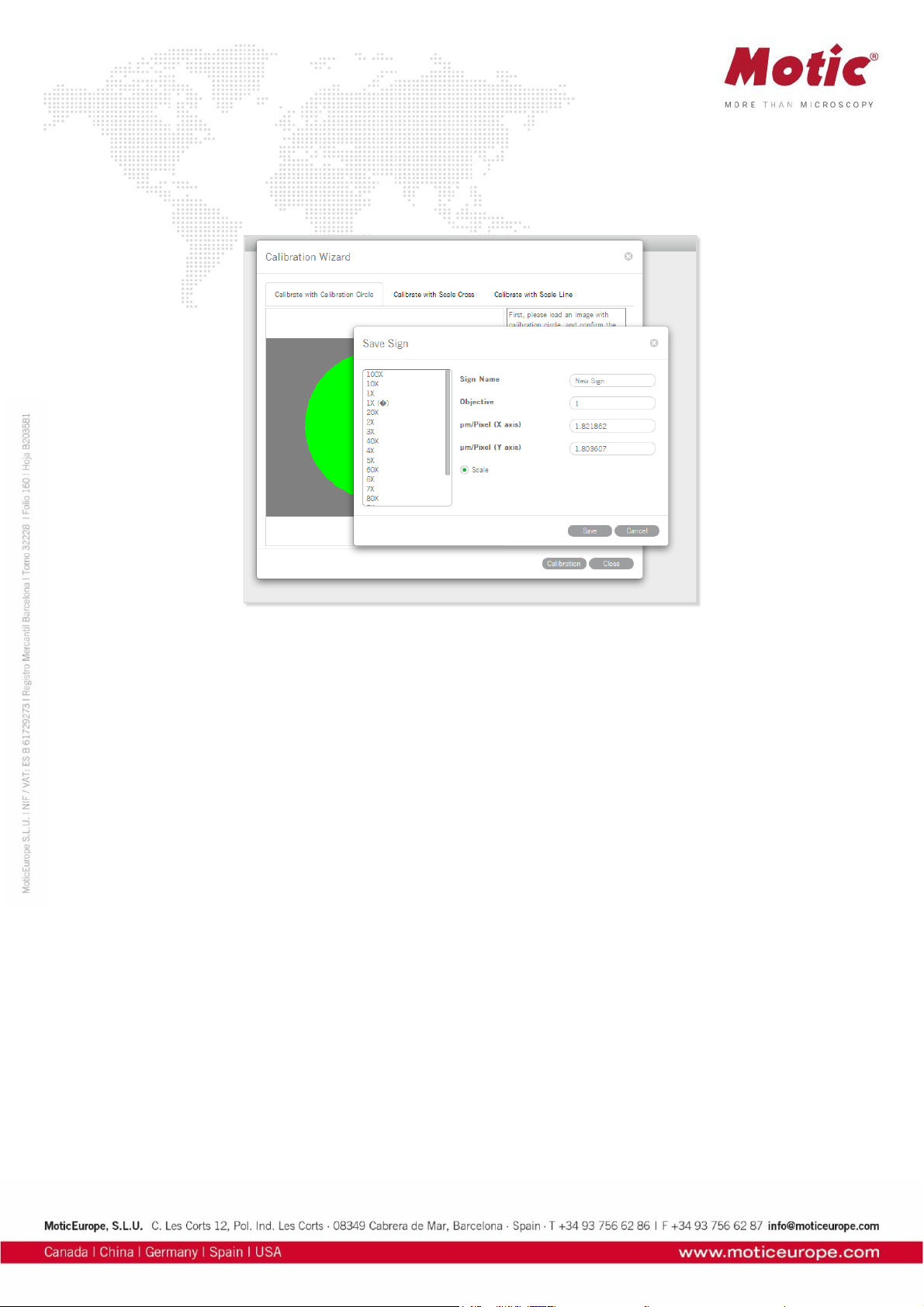
Activate the “Scale” option (if not active by Default setting). This function will adjust e.g. the scale bar
value depending on the display mode (resolution, Full screen). Enter a New Sign Name to refind your
calibration easily within the calibration table. Next, click the Save button to finish calibration.
Calibrate... / ... with Scale Cross
To calibrate with a scale cross, select the respective Calibration Wizard.
Click Load Image button to select a scale cross from your image database.
When the image is loaded, a circle will appear on the scale cross. If desired, choose a different color.
Place the center of the circle (set as "O") exactly into the center of the scale cross. Next, take a reddish
marked point ("A") in the X-direction and drag it on the horizontal line to a certain scale division, then
perform identically in Y-direction ("B"). The magnifier window under the image window may help to
accurately place the points.
Confirm the objective lens used to capture the selected image and input the actual length of "OA" in the
"Width" bar and the actual length of "OB" in the "Height" bar. Take note about the scaling of the scale bar.
Click the Calibration button to open a new dialogue box. Continue as under Calibration with
Calibration Circle.
Page 38
Calibrate... / ... with Scale Line
To calibrate with scale line, select the respective Calibration Wizard. This wizard performs calibration in
X- and Y-direction separately, using the same image type: the scale cross.
Click Load Image to open the image of a scale cross.
Click the Horizontal tab to activate a horizontal line overlaying the scale cross. If desired, choose a
different color. Extend the line by dragging with the left mouse button to a defined scale division. Confirm
the objective lens used to capture the selected image and input the actual length.
Page 39
Please repeat this procedure for Y-direction (Vertical tab).
Click the Calibration button to continue as in Calibration with Calibration Circle.
When calibration is completed, click Save to close the Calibration Wizard.
Page 40
The Calibration Table shows all calibration data saved for later usage.
If the Scale check box is selected, the measurement results will stay correct, no matter which display
format/resolution is used.
Page 41

Motic Live Imaging Module
Windows OS User Manual
Page 42

Introduction 05
Menus, bars and tools 06
Title bar 06
Menu bar 06
Status bar 07
FPS 07
Magnification 07
Magnification Stamp 07
ROI Preview 07
Calibration 07
Image Preview Window 07
Control Panel 08
Basic adjustments 08
Video device 08
Resolution 08
Exposure time 08
Gain 08
Offset 08
Enhance 09
Gamma 09
White balance 1 09
White balance 2 09
Background Balance 09
Mirror 09
Flip 09
Fit to window 09
Full 09
Color adjustments 10
Color correction 10
Red Gain 10
Red Brightness 10
Green Gain 10
Green Brightness 10
Blue Gain 10
Blue Brightness 10
CONTENTS (Linked)
Motic Live Imaging Module | Windows OS User Manual
Page 43

Reset 10
Histogram enabled 10
Advanced Settings 11
Filter 11
Invert 11
Grayscale 11
Emboss 11
Red 11
Green 11
Blue 11
Red inverted 11
Green inverted 11
Blue inverted 11
Edge detection 11
Sharpness 11
Remove noise 11
Grid 11
Grid Setting 12
Scale Cross 12
Color 12
Scale Bar 12
Setting scale bar 12
ROI 12
ROI Ellipse 12
ROI color 12
Calibration 13
Calibration Table 14
One-click Calibration 14
Preset 14
Load 14
Save 14
Delete 14
Cooler Enabled 14
Pro Options 15
Histogram 15
Capture a highest resolution image 15
Capture a high quality image by average of several frames of images 15
Capture a high quality image by adjust gain value to 1X 15
Page 44

Enable topmost image 15
Enable Motic Hub 15
Version 15
Video capture 15
Format 16
Capture 16
Auto Capture 16
Trigger Capture 16
Record 16
Measure 17
Arrow 17
Line 17
Rectangle 17
Ellipse 17
Circle 17
Angle 18
Circle (3 points) 18
Arc (3 points) 18
Polygon 18
Text 18
Freehand Line 18
Parallel Line 18
Delete 18
Settings 18
MoticHub 19
Enable MoticHub function 19
Access MoticHub 19
System Configuration 20
Page 45

This software module is meant to improve a live image before capturing a final picture. Several
parameters to adjust the live image like resolution, white balance, color correction etc. can be varied
simply and optimized interactively. Exposure time can be set according to the illumination situation of the
microscope. The default capture folder for still images and videos can be defined. Further processing and
image analysis is possible in a separate software module, an integral part of the complete software
package Motic Images Plus 3.0.
Double click with left mouse button on
opens the program. Please note before installation that the new software version MI Plus 3.0 is available
in separate versions for 32- and 64 Bit computers. This is in contradiction to the previous Motic Images
Plus 2.0 software version.
To open the Live Image Module, click on “Motic Imaging Device” in the left column.
The Live Imaging Module opens.
Page 46

Menus, bars and tools
The new interface consists of the Title Bar, Menu Bar, Status Bar, Image Preview Window and Control Panel.
Menus, bars and tools / Title bar
Displays the module name and shortcut menu.
Note: The shortcut menu is available under Windows OS only.
Menus, bars and tools / Menu Bar
Displays the basic menu:
Help
Click the button to open the Help dialogue.
Language
Change the interface language from the dropdown menu. This can be done without shutdown of the software.
Style
Change the interface style.
Page 47

Menus, bars and tools / Status Bar
FPS
Frames per second = Frame rate.
Magnification
Select the current objective you are using on the microscope. After calibration the scale bar will show the
correct value.
Magnification Stamp
Click to display/hide the selected objective displayed on the uppermost right side of the image.
ROI Preview
To view only a selected part of the image in full resolution, click and drag a Region Of Interest on the live
image with your left mouse button, then click the "ROI Preview" button. Click the button again to restore
the original image. The shape and border color of the ROI can be set in the Advanced Setting Panel.
Calibration Value
Select a calibration value from the “calibration value” dropdown list and the currently measured value will
be changed.
Menus, bars and tools / Image Preview Window
Displays the real-time live image coming from your Moticam or Digital Microscope. Click the button on the
title bar to hide this window, re-click to display it again.
Page 48
Menus, bars and tools / Control Panel
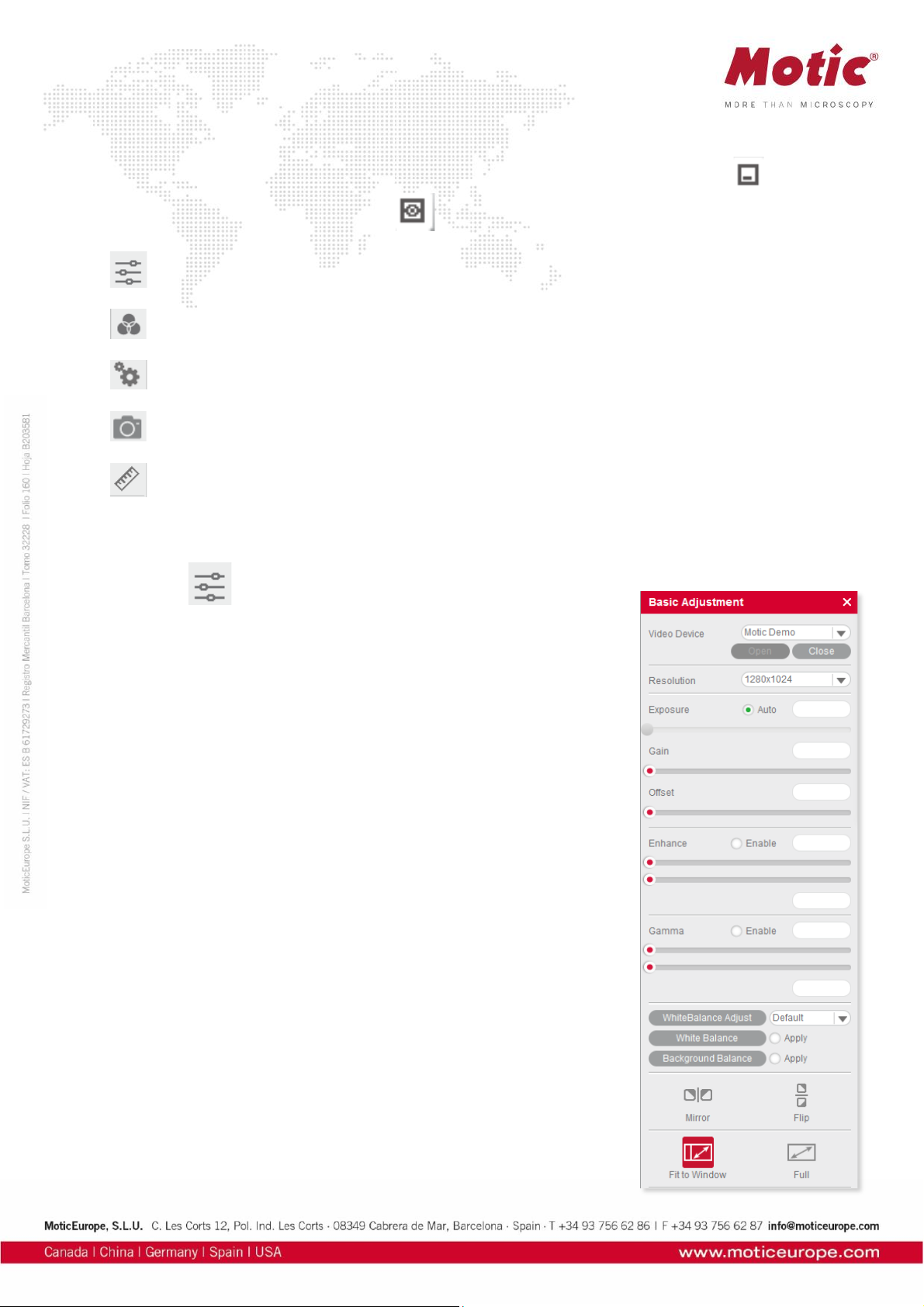
Click one of the following icons to display the corresponding control panel. Click the button on the
title bar to hide the control panel, click on to display it again.
Basic Adjustments
Color Adjustments
Advanced Settings
Image/Video Capture
Measurements
Menus, bars and tools / Control Panel / Basic Adjustment
The button opens the Basic Adjustment Panel to perform basic device settings and image adjustments.
Video Device
Displays the connected imaging device.
Note: If several Motic devices have been connected and the auto-opened
device is not what you want, please click "Close", select the desired
device from the dropdown list and click "Open". MoticamX and Motic
Demo are named per default.
Resolution
You can switch between different resolution settings. The setting changes
the amount of data that are transmitted to the computer by the imaging
device. The higher the resolution the lower the frame rate (FPS).
Exposure Time
Setup your microscope properly and focus on your slide. With “Auto” you
will get a first image. If necessary, deactivate “Auto” and correct the
exposure time by moving the respective slider. Especially with high
contrast samples, this manual adjustment is recommended.
Note: Some camera chips have built-in auto-exposure controls. If you
wish to override, use the slider to adjust the settings manually.
Gain
This function is an electronic amplification of the sensor signal
(“brightness”). It increases also the electronic noise. Should only be used
if the image brightness cannot be adjusted properly by exposure time (e.g.
moving = living samples).
Offset
Sets the “zero” brightness value. Recommended to be used for POL, dark
field or Fluorescence. Move the slider to minus values.
Page 49

Enhance
With two sliders, the minimum and maximum gray level value can be set independently. The image data
will be re-mapped according to the settings in order to enhance contrast.
Gamma
“Gamma” translates the electronic image signal from the camera sensor into image brightness on the
respective monitor. Depending on screen technology and screen setup (LCD, LED, etc.) the
brightness/color impression can be set individually.
White Balance 1
"White Balance" will help to get the best possible color similarity to what you see through the eyepieces.
Setup your microscope properly and focus on your slide. You may remove the slide from the microscope
and click on the "White Balance" button. Or you may keep the slide on the stage and look for an “empty”
area within your sample. With left mouse button pressed please define a “background” area without color;
activate “White balance”. Once defined, this setup can be overwritten arbitrarily.
Note: Some imaging chips have an automatic hardware white balance. You will see the white balance
being adjusted automatically as close to the real color as possible. In order to adjust the color even
closer, please use the tools in the Color Adjustment Panel.
White Balance 2
Several types of microscope illumination (Halogen, LED 3000K, LED 5000K) can be chosen from the list.
Further, the backround color may be selected by clicking into the color field. The chosen setup can be
saved.
Background Balance
The “Background Balance” function reduces the effects of uneven illumination, mostly caused by the
camera adaption. Please setup your microscope properly, focus on your slide and adjust the
microscope's illumination. Take the slide away from the stage and activate "Background Balance". The
screen now displays a background calculated as even. Place the slide back onto the stage. The power of
"Background Balance" is limited: it does not work with an extreme uneven/incorrect illumination.
Note: If necessary, please perform the above steps again when changing the objective.
Mirror
To mirror the live image horizontally.
Flip
To rotate the live image by 180°.
Fit To Window
The live image will be resized to fit into the display window, allowing to show the camera's full Field of
View. The width-to-height ratio will be kept.
Full
To view the live image in full screen mode. Press "Esc" to exit the full screen mode.
Page 50
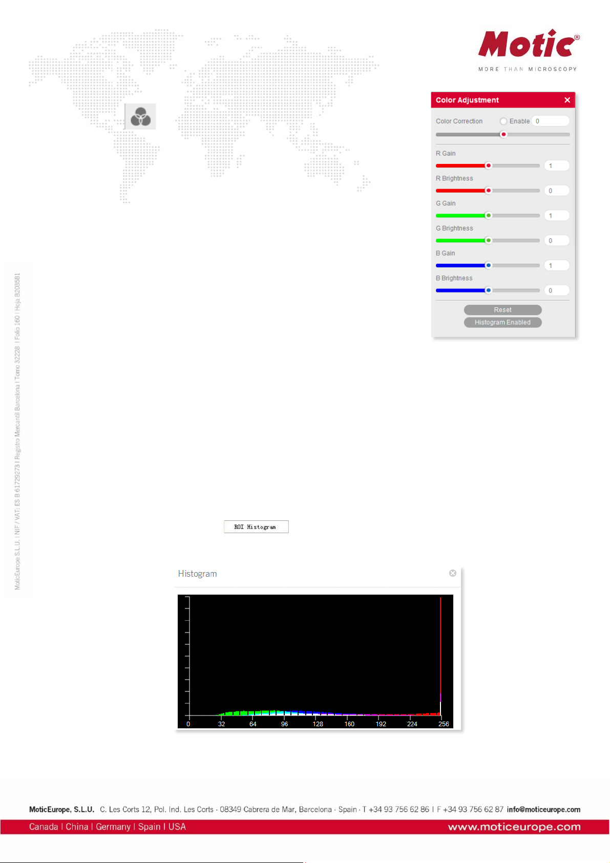
Menus, bars and tools / Control Panel / Color Adjustment
The button opens the Color Adjustment Panel.
Color Correction
Click "Enable" to activate this function. Positive values amplify the colors,
especially in the blue/red range (H&E stainings). Negative values reduce the
color impression down to a black/white image. We recommend a +7 setting.
Red Gain
Electronic amplification of the RED channel.
Red Brightness
Adjust the red channel brightness value by dragging the slider.
Green Gain
Electronic amplification of the GREEN channel.
Green Brightness
Adjust the green channel brightness value by dragging the slider.
Blue Gain
Electronic amplification of the BLUE channel.
Blue Brightness
Adjust the blue channel brightness value by dragging the slider.
Reset
Click the "Reset" button to restore the factory settings.
Histogram Enabled
The histogram shows the gray value distribution within the entire image or a user defined ROI. The
horizontal coordinate represents the gray scale 0-255, while the vertical coordinate represents the gray
value frequency per color channel.
By default, the histogram function is applied on the entire image.To display the histogram of a user
defined ROI, first drag the mouse in the image preview window to define an ROI, then activate the
histogram window and select the command, click the command again to cancel it.
Page 51

Menus, bars and tools / Control Panel / Advanced Settings
Click the button to open the Advanced Setting Panel for further
adjustments and measurements.
Filter
First drag the mouse in the Image Preview Window to define an ROI, then
select a filter from the drop down list.
Invert
Inverts the color/brightness information of the original.
Grayscale
Creates a B/W image.
Emboss
Creates an embossed image.
Red
Only the red color channel is displayed.
Green
Only the green color channel is displayed.
Blue
Only the blue color channel is displayed.
Red inverted
Combines Red and Invert.
Green inverted
Combines Green and Invert.
Blue inverted
Combines Blue and Invert.
Edge Detection
Drag the mouse in the Image Preview Window to define an ROI, then check the Edge Detection box and
drag the slider bar to adjust the sensitivity for enhancing the edges of objects within the defined ROI.
Sharpness
Activates the Sharpness function. Set the sharpness value by adjusting the slider bar.
Note: This function only works on the whole image.
Remove Noise
Activate this function and select a value from 1-4.The larger the value, the greater the effect and the
slower the live image will be.
Note: This function only works on the whole image.
Grid
Click to display the grid lines in the Image Preview Window.
Page 52
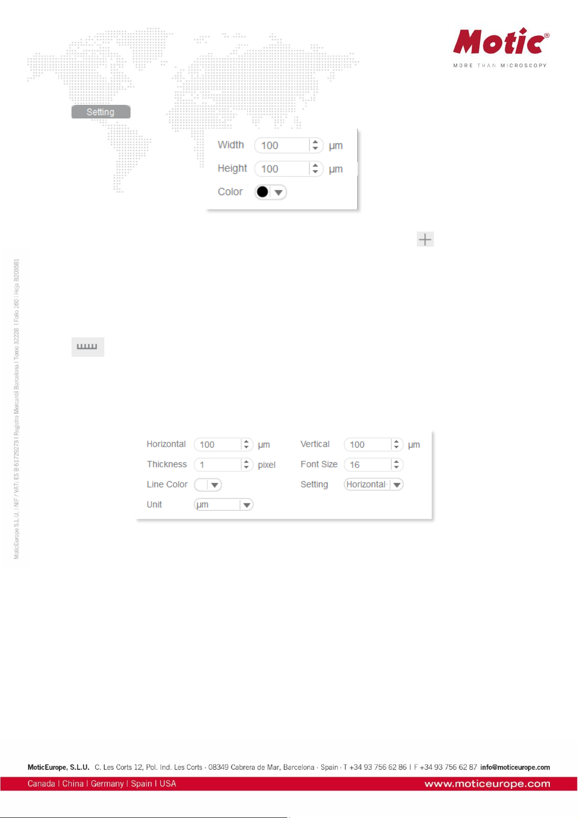
Grid Setting
allows to set the width, height and color of the grid.
Scale Cross
The Scale Cross function is used for an identical positioning of multiple samples. activates the Cross
Line; per default first in the middle of the preview window. The coordinates displayed are pixel
coordinates. In order to move the Scale Cross to a different position, please use the right mouse button.
Color
The color of the Scale Cross can be selected.
Scale Bar
activates a horizontal and/or vertical scale bar. To move the individual scale bar, use the left
mouse button to drag and drop it to the desired position.
Setting Scale Bar
To edit the Scale Bar, please use the following menu:
ROI Properties
Ellipse ROI
The default rectangle ROI shape will be converted to an elliptic ROI.
Color
Click the color bar to set the ROI's border color from the displayed color palette.
Page 53

Calibration
Any kind of measurement, scale bar or grid needs a precise calibration for a correct quantification.
Place the calibration slide (within the delivery package of your Moticam) into the raypath of the
microscope and focus one a calibration circle (in fact it’s a dot). Depending on the objective/camera
adapter/camera sensor combination, the correct dot has to be chosen. As all dots on the calibration slide
are placed in one line, it is easy just to use the x-drive of the microscope stage to move from one dot to
another. Before taking a picture, note that the selected dot should be grabbed completely, at the same
time being be as large as possible in the image field. This will improve the precision of all measurements.
Open the calibration dialogue and load the picture taken:
Select the magnification of the objective used for taking this picture, enter the diameter of the calibration
dot (vacuum-metallized on the calibration slide) in the corresponding box. With "Calibration" the following
interface opens:
Select a unique sign name which can easily be fould again in the calibration table. "Zoom" should be
activated by default. If not, please do activate. This setting ensures that all quantification data (scale bars,
grids, measurements) are automatically adjusted to the active display mode on the screen (varying
resolution, full screen, etc.), thus being active also when saving the image. Please check the x/y-axis
values: they should be as identical as possible (one decimal place difference should be maximum). Click
"Save".
Page 54

Calibration Table
The Calibration Table saves all new calibrations. In the initial state, the default data displayed in this table
are “factory data” and are marked with "false" in the "Zoom" column.
To apply yor individual calibration results, select the necessary calibration from the list, which should be
marked as "true" in the "Zoom" column (if you had activated “Zoom” during the calibration process).
With the selection of a calibration, all data for scale bar, grid width and measurements will be updated
automatically.
To delete calibration results from the table, select a desired item and click "Delete".
One-Click Calibration
This kind of “calibration” does not refer to quantitatification, but to predefined camera settings for three
types of microscope samples (Biological,Metallographic,Stereo):
Preset
With this function, you may save and load the parameters you have set with “Basic Adjustments”,
“Color Adjustments” and “Advanced Settings”.
Load
The next time you wish to return to these settings, select from the dropdown list, click "Load" and the
settings in the corresponding panel will change accordingly.
Save
Adjust the parameters in the corresponding panel until the image quality meets your requirements; enter
a name in the blank and click the "Save" button to save these settings.
Delete
Click "Delete" to remove the current item from the list.
Cooler Enabled
Check "Cooler Enabled" to enable the cooler of a Moticam Pro camera with Peltier cooling.
Page 55
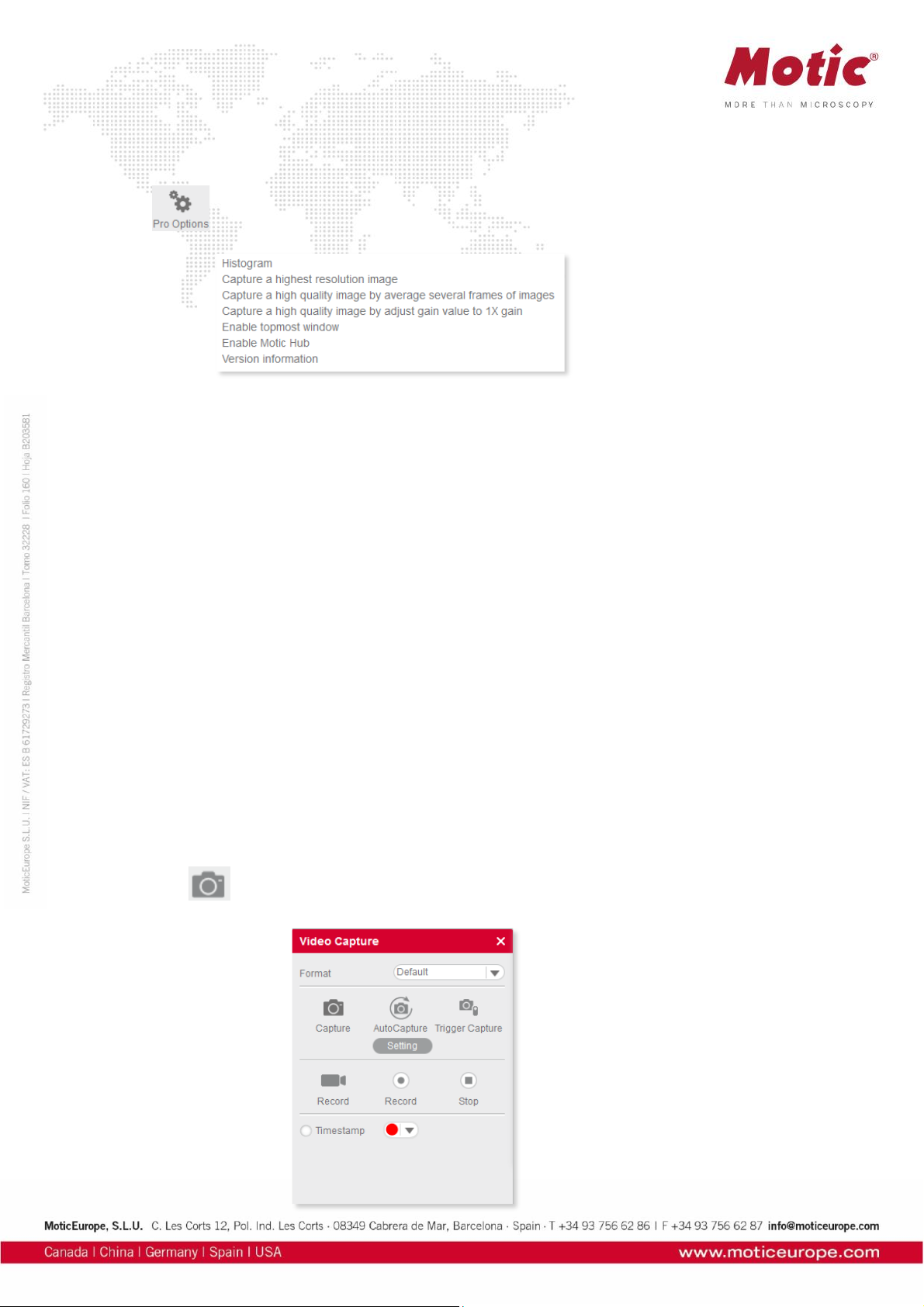
Pro Options
Click to display the following options:
Histogram
Opens the histogram window.
Capture a highest resolution image
Captures an image with maximum resolution, no matter what resolution is used at the moment.
Capture a high quality image by averaging several frames of images
Captures continuous 4 images at the current resolution to merge a high quality image (with reduced noise).
Capture a high quality image by gain value to 1X gain
Adjusts the gain value to 1X and captures a high quality image (graph camera signal/monitor brightness with gradient 1X).
Enable topmost image
Bring the live image into the foreground.
Enable Motic Hub
Activates the Motic Hub function; your computer will be able to transmit the live image as a WiFi signal.
Version
Software version
Menus, bars and tools / Control Panel / Video Capture
The button opens the Video Capture Panel for image capturing and video recording.
Page 56
Format
From the dropdown list "Format" select an image size to capture an image. If "Default" is selected, the
size will be the current display resolution. If you choose a higher resolution, the image will be
extrapolated.
Capture
Captures a complete Still Image or only a defined ROI. Selection of an ROI allows to indidually define the
region you like to document.
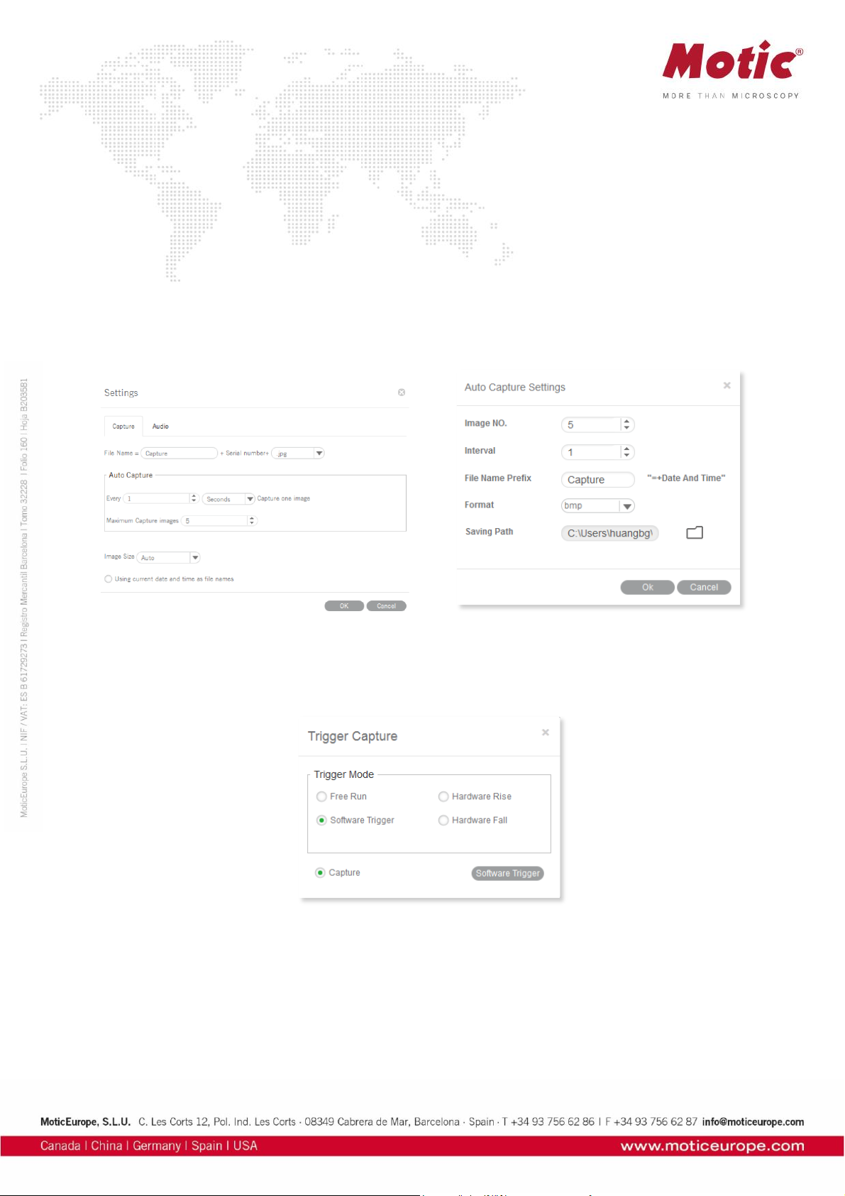
Auto Capture
The definition of a sequence of Still Images is per default done through “Settings” in the main software:
Number of images, chronological distance, format and name.
If you open this module directly without opening the main software, a slightly different dialogue will
appear:
Trigger Capture
Only possible with Moticam Pro models. Freezes and captures the current image.
Note:”Hardware Rise” and “Hardware Fall” are available with a camera having a hardware trigger feature.
Record
Specify a path to save a video. A time stamp for Still Images and videos can be applied.
Page 57

Menus, bars and tools / Control Panel / Measure
The MIDevice live measurement module greatly simplifies the workflow and improves the efficiency as
the user does not need to capture an image before performing measurements.
The button opens the Live Measurement Panel for interactive measurements.
Arrow
The length of the arrow will be displayed.
Straight Line
The length of the straight line will be displayed.
Rectangle
Height, width and area of the rectangle will be displayed.
Ellipse
Width, height, perimeter and area of the ellipse will be displayed.
Circle
Radius, perimeter and area of the circle will be displayed.
Page 58

Angle
Depending on the drawing direction, the measurement of an internal or external angle is possible.
Circle (3 Points)
Draw a circle with three points and radius, perimeter and area are displayed.
Arc (3 Points)
Draw an arc with three points and radius, length and angle are displayed.
Polygon
Draw a polygon and measure perimeter and area.
Text
Draw a rectangular text field for comments.
Freehand Line
Displays the length of a freehand line.
Parallel Line
Draw parallel lines in the image and measure their distance.
Delete
Select one figure to delete; double click to delete all figures from the image.
Settings
Allows to edit the measuring data.
Note: To ensure correct measurements, please perform calibration before doing a live measurement.
Page 59
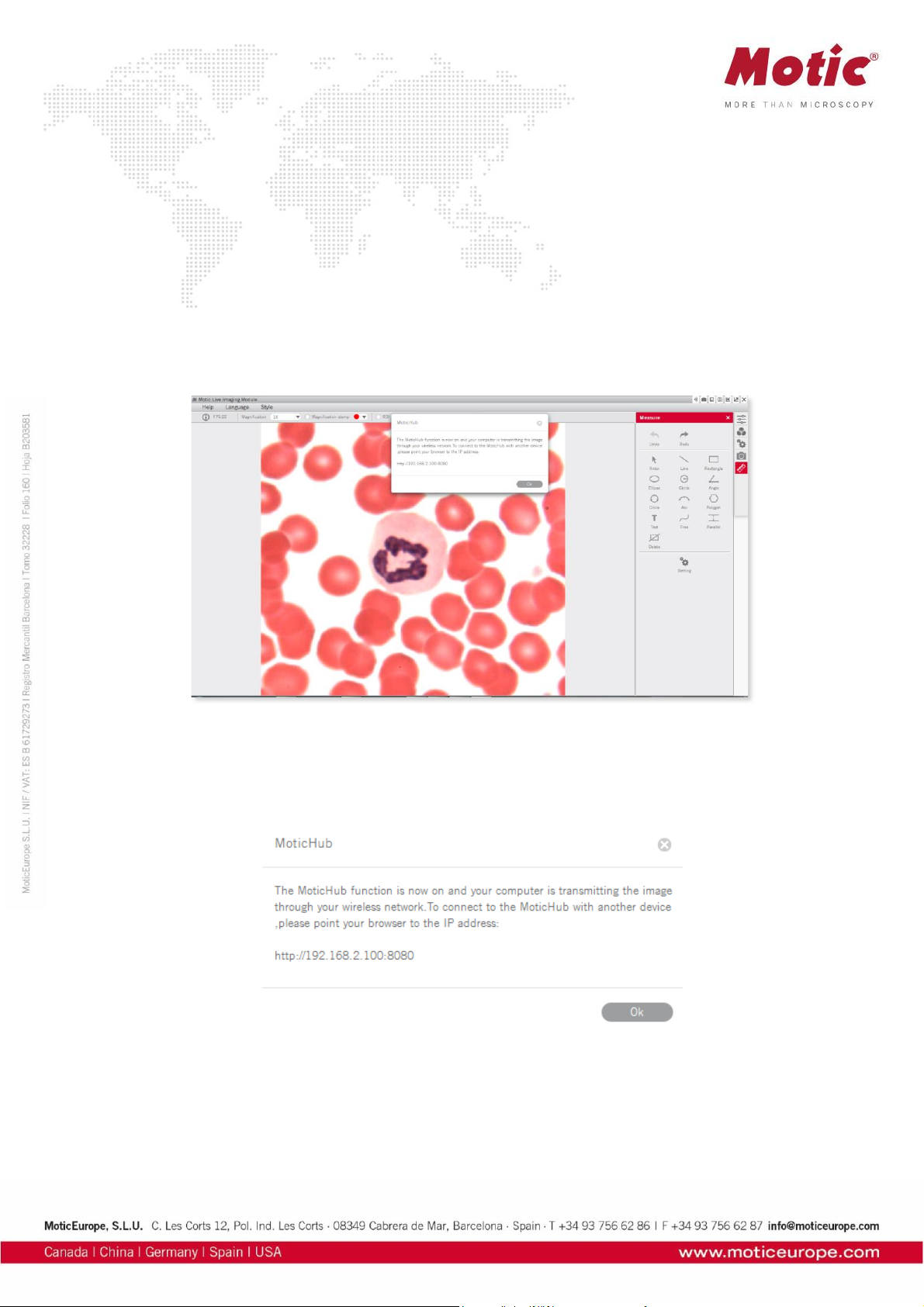
MoticHub
MoticHub can transmit the live image from an MIDevice source via WiFi to a variety of recipients (PC,
laptop, tablet, smart phone). A variety of browser (Google Chrome, Moticonnect App) display the live
image with an interactive parameter setting.
Enable the MoticHub function
1. Please connect your computer to a wireless network (router).
2. Connect your Motic camera to a computer.
3. Please click the “Wi-Fi” button in the title bar to enable the MoticHub function.
Access MoticHub
The WiFi signal can be handled by PC browser or Motic APP (free of charge) on an external device.
Please connect the mobile device or computer to the MoticHub network (wireless router or Wi-Fi hotspot),
then launch browser and enter http:// IP address /port number.
Compatible Browser: FireFox, Chrome, Safari.
Compatible Operation System: Windows, Mac OSX, Linux, IOS and Android 4.0 or higher OS.
Through GooglePlay the relevant MotiConnect App (free of charge) is available.
Page 60

System Configuration
Minimum configuration requirements
CPU: Intel(R) Pentium(R) 4; 2.8GHz or higher
Memory: 512MB or more
Display: Standard VGA 32MB color, no less than 1024x768, supporting DirectX 8.0
HD space: 500MB or more
Sound card: Common full duplex sound card
Recommended configuration
CPU: 2 x Intel(R) Pentium(R) D; 2.8GHz or higher
Memory: 1G or more
Display: Standard VGA 32MB color, no less than 1024x768, supporting DirectX 8.0
HD space: 10GB or more
Sound card: Common full duplex sound card
 Loading...