

Page 1

Instruction Manual
B1 Series
Copyright © 02/02
Motic Microscopes, European Division
Page 2
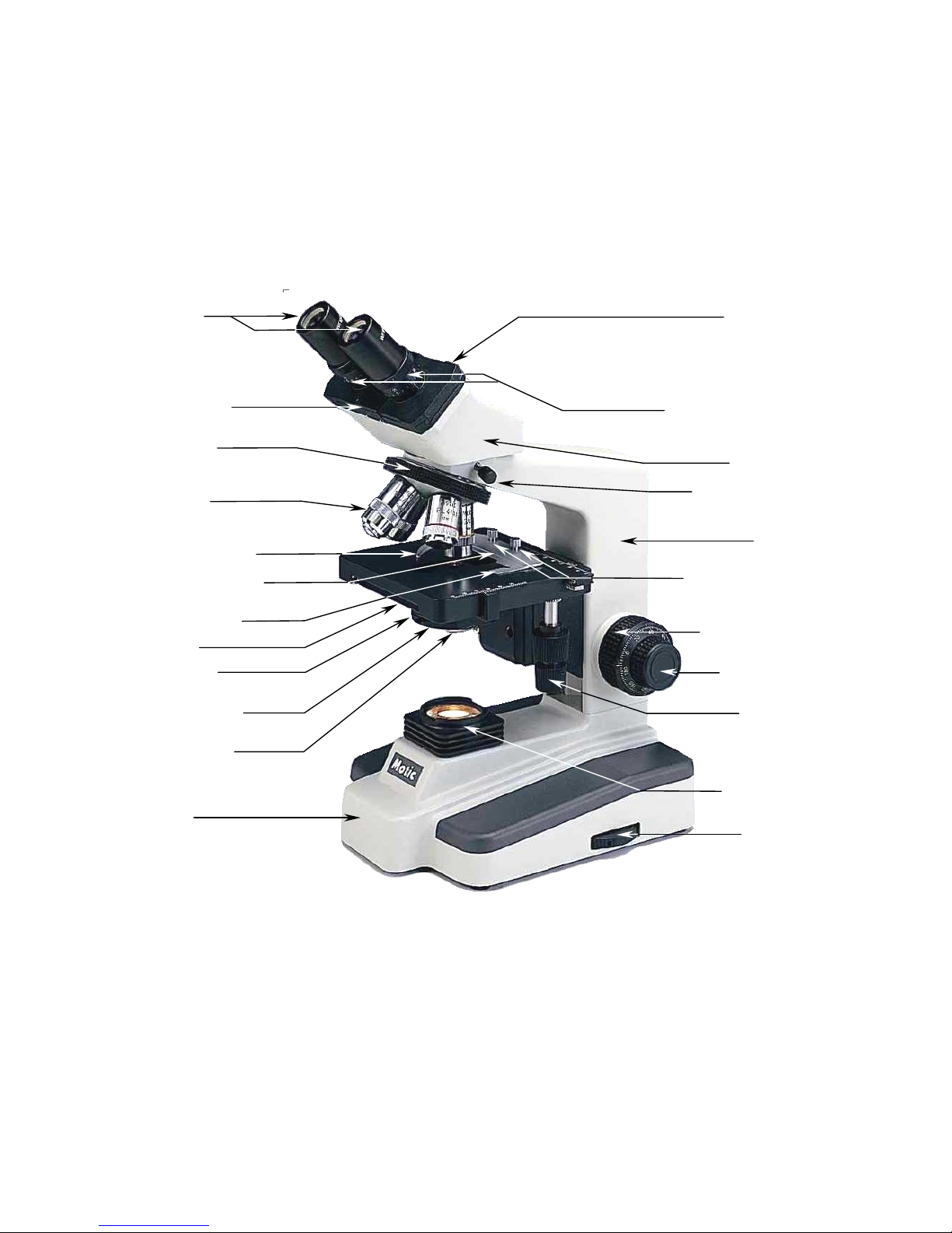
1. Eyepieces 13. Sliding
interpupilliar
y
adjustment.
2. Interpupillary
Scale
3. Revolving
Nosepiece
4.Objectives
5. Moveable finger
6. Specimen holder
mechanism
7. Slide holder
8. Stage
10. Condenser
9. Diaphragm
15. Head
17. Arm
14. Eyepiece tube with
diopter correctors
18. Knurled locking
screws for securing
specimen holder
19. Coarse Focus
Knob
20. Fine Focus
Knob
21. Knobs
controlling
16. Knurled locking
screw
stage movemen
t
11. Filter holder
22. Illuminato
r
12. Base
23. Ligh
t
intensity control
B1-220A
-2-
Page 3

Introduction
Thank you for your purchase of a Motic microscope. Motic microscopes are precision instruments, subjected
to meticulous examination in order to reach you in perfect condition. Their design combines easy
management and optimum functioning with minimum maintenance.
The information contained in this manual is likely to go beyond what the average user needs to know to use
the microscope, however, it is provided to answer any queries that may arise.
Your new microscope combines high performance features, with an excellent degree of optical resolution
and clarity of image. It incorporates a mechanical stage that provides a travel range of 70mm x 50mm in X
and Y directions with a graduation of up to 0.1 mm, thus permitting the perfect positioning of the specimen.
Also included are objectives located on a ball bearing nosepiece allowing movement in both directions; a
precision coarse and fine focusing system; a moveable Abbe condenser with a numerical aperture of 1.25
N.A. and a built-in 12V/ 20W halogen variable light source.
These instructions should be read carefully before operating the microscope. They will permit you to use
your new microscope to its fullest capabilities. Terminology used to describe components and controls can
be found in the diagram on page 2.
These instructions are based on the assembly and use of the B1-220 model (Binocular) with
additional notes applying specifically to other models in the series.
Unpacking
All components of the microscope have been carefully packed to make sure they reach you in perfect
condition. We recommend that you do not discard any packing containers in case you need to return the
microscope, store it for long periods of time; or should it become necessary to transport it to a technical
service for any repair, or maintenance procedure.
The box should contain the following components, depending on the model:
• B1-211 (Monocular): Stand, Power cable, monocular head, eyepiece, eyepiece protector, four
objectives, condenser, sample holder mechanism, blue, green and yellow filter, fuse, dust cover, a
bottle of immersion oil and a 2mm hexagonal key.
• B1-220 (Binocular): Stand, Power cable, binocular head, two eyepieces, two eyepiece protectors,
four objectives, condenser, sample holder mechanism, blue, green and yellow filter, fuse, dust cover,
a bottle of immersion oil and a 2mm hexagonal key.
• B1-223 (Trinocular): Stand, Power cable, trinocular head, two eyepieces, two eyepiece protectors,
four objectives, condenser, sample holder mechanism, blue, green and yellow filter, fuse, dust cover,
a bottle of immersion oil and a 2mm hexagonal key.
Remove, and handle the microscope and all its components with extreme care.
Avoid touching the lenses of the optical elements and keep clear of contact with dust, water or other
contaminating agents, as they could stain, or damage the lens surface and affect the quality of the
image.
A. Place the microscope in an upright position on a flat, stable and clean surface.
B. Unscrew the black plastic protectors from the revolving nosepiece (3).
C. Remove the rest of the components from the box.
-3-
Page 4
Assembly
All the steps described for the assembly of the microscope must be undertaken with extreme care,
and without forcing the placement of the distinct parts and elements of the microscope.
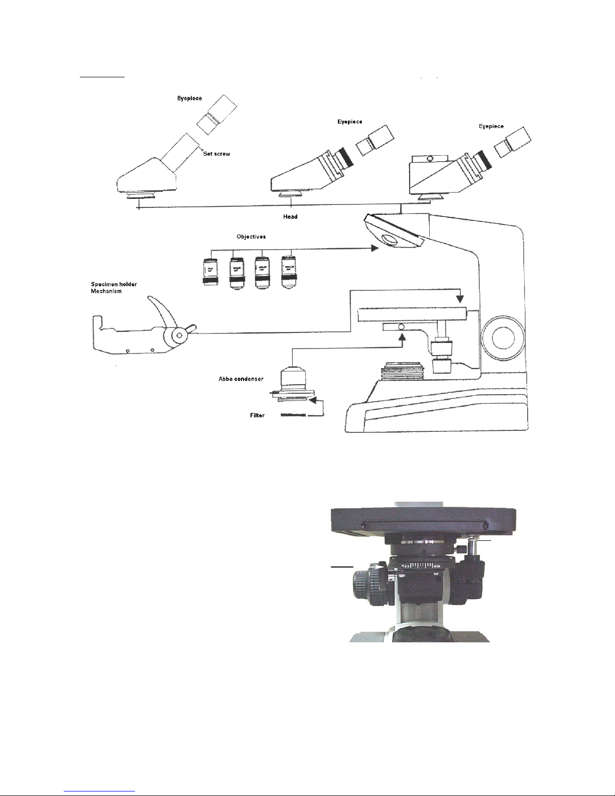
A. Condenser (10): Turn the coarse
focus knob (19) until the stage (8)
reaches its highest position. Turn
the focussing knob on the
condenser (Fig.1) until the
condenser holder reaches its
lowest position. Unscrew the
knurled locking screw on the
condenser, and insert the
condenser in the mounting ring so
that the aperture of the diaphragm
(9) faces the front of the
microscope and so can be
adjusted easily. Once firmly
placed in the mounting ring, firmly
tighten the locking screw, and turn
the condenser focusing knob until
in its highest position.
Condense
r
set screw
Condenser
focusing
knob
Fig. 1
-4-
Page 5
B. Specimen Holder Mechanism (6): Turn the Coarse Focus Knob (20) until the stage (8) reaches its
lowest position. Unscrew the two knurled locking screws (18) of the specimen holder mechanism.
Place the mechanism on the stage with the moveable finger lever facing upwards (5) so that the
holes of the mechanism line up with the locking screws. Firmly screw the screws back into place.
C. Objectives (4): Ensure that the revolving nosepiece (3) is well positioned: i.e. that it does not revolve
freely, but rotates until a “click” is heard, showing that it is secure in place. Place objectives, starting
with the lowest magnification 4X in any of the holes in the revolving nosepiece. Next, place that of
the second lowest magnification 10X in the hole alongside, and so forth: the 40X objective, and
finally the 100X objective can be placed.
D. Head (15): Loosen the knurled locking screw on the head and remove the protective cover on the
collar where the head is placed. Insert the head, until it is well supported on the stand (17). Although
the head can be placed in any position, we recommend for your comfort that the eyepiece tubes (14)
face forward on the microscope. Firmly re-tighten the knurled locking screw.
E. Eyepieces (1): Remove the protective covers on the eyepiece tubes (14). Gently place the eyepieces
in the tubes without touching the lens surface.
• B1-211 and B1-212: Remove the
protective cover on the eyepiece tube.
Using a jewellers screwdriver, loosen the
tiny screw situated on the lateral of the
tube. Gently, and without touching the
surface of the lens, place the eyepiece in
the tube. Re-tighten the locking screw on
the eyepiece.
F. Filter: Swing out the filter holder horizontally
and place the blue filter in the filter holder
(11) located under the condenser (10). Make
sure that the filter is well positioned.
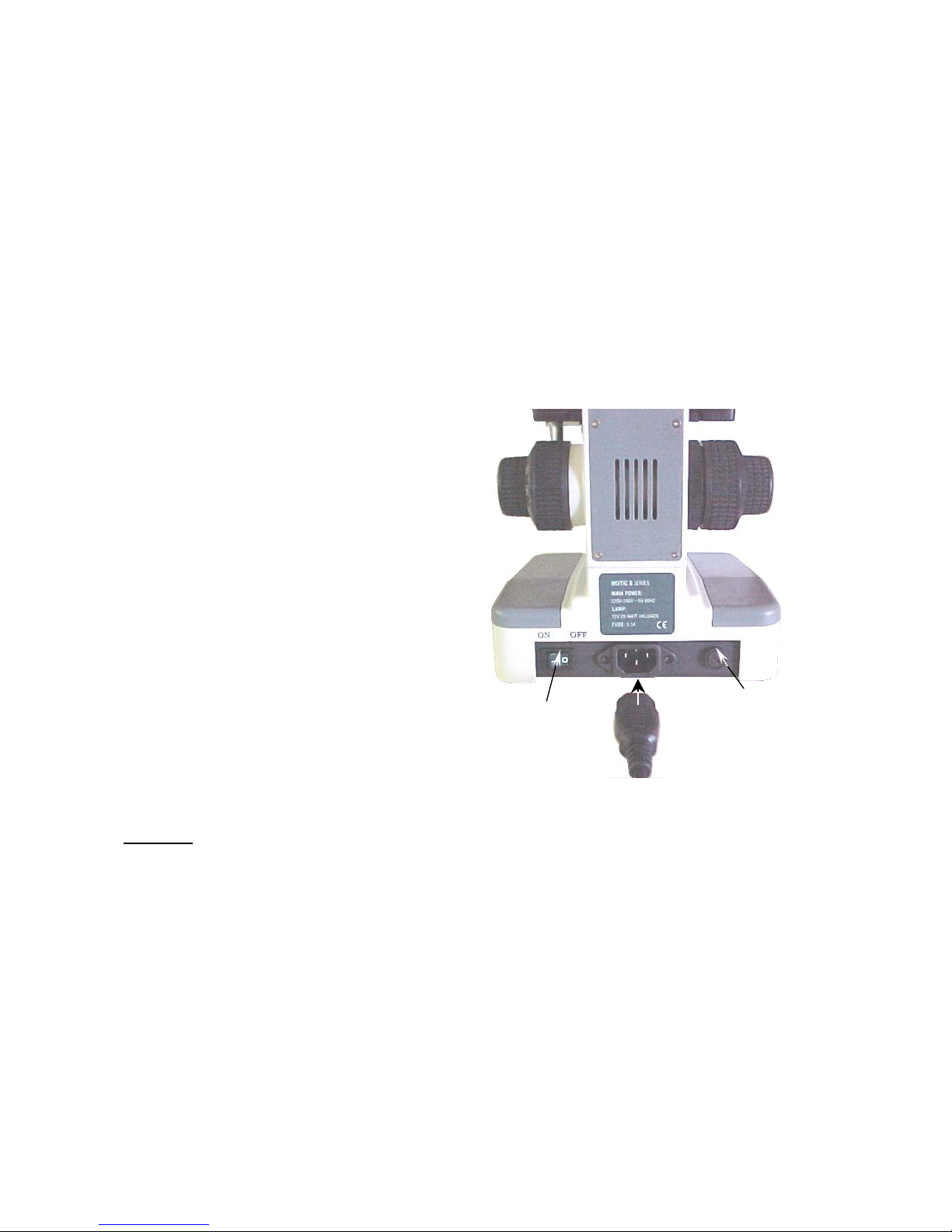
G. Power cable: Insert the power cable in the
connector at the lower back of the
microscope. (Fig. 1)
On switch
Fuse
Fig. 2
Warning: Before connecting the microscope to a
power source, check that the voltage coincides with
that on the microscope.
Operation
A. Starting up.
1. Before using the microscope, adjust the light intensity control (23) to minimum position. This
should be repeated every time the microscope is switched on or off to prolong the use of the
bulb.
2. Press switch to ON position. (Fig. 2)
3. Turn illumination control until the image is illuminated.
4. Light intensity must be adjusted according to the objective used, or the type of preparation to
be observed.
-5-
Page 6

B. Interpupillary adjustment of head. (Only for models B1-220 and B1-223)
1. Look through the eyepiece and adjust the distance between the eyepiece tubes (14) by
grasping the head, by its four gripped corners (13), and moving it horizontally.
2. When a full field of view is observed through both lenses, and images blend into one, the
interpupillary distance is correct for the user’s eyes. Take note of the index reading marked
in the interpupillary scale (2) for the following step.
3. Adjust the diopter scales (14) situated on both eyepiece tubes until the reading of both
scales coincides with the value of the interpupillary distance scale. This step is necessary to
maintain the parfocality of the objectives.
4. Readjust the diopter scales for variation in interpupillary distance.
C. Focusing the microscope.
1. Turn the revolving nosepiece (3) and place the 4X objective (4) in the optical path ensuring
that it is properly clicked into place.
2. Turn the coarse focus knob (19) until the stage (8) is in its lowest position.
3. Place a microscopic sample on the stage, make sure the cover slip faces upwards.
• Swing the moveable finger (5) on the mechanism (6), place specimen against fixed side
of slide holder (7) and gently release the moveable finger until the specimen is
supported in place.
4. Make sure that the specimen is in the optical path by adjusting the stage using the knobs
controlling the X/Y movements (21).
5. Looking through the eyepiece, turn the coarse focus knob until the preparation appears in
focus.
6. Readjust the focus with the fine focus knob (20) until the image appears sharply defined.
D. Adjust diopter for differences in eyesight. (Only for models B1-220 and B1-223)
1. With your right eye, look into the right eyepiece tube (1) and adjust the sharpness of the
image using the fine focus knob (20).
2. With your left eye, looking through the left eyepiece, adjust the focus by rotating the diopter
corrector (14) on the left hand eyepiece tube until the image is sharp. Do not use the fine
focus knob.
E. Adjusting the aperture of the diaphragm.
The aperture of the diaphragm (9) should not be used to control the brightness of the light.
Diaphragms are designed to obtain high resolution of the sample, and provide contrast in the
image. Smaller apertures will deliver higher contrast to image. However, closing the aperture
too much will reduce resolution. Experimentation is the best method of determining the
correct aperture of the diaphragm. Suggested apertures for each objective are as follows:
OBJECTIVE APERTURE OF IRIS
4X From fully closed to 1/8 open.
10X From 1/8 to 1/4
40X From 1/4 to 1/2
100X From 1/2 to 3/4
-6-
Page 7

F. Changing magnification.
1. Position the 10X objective (4) in the optical path.
2. This microscope has been parfocalized, although it is possible that small differences exist
between objectives. If so, adjust focus slightly using the fine focus knob (20).
3. When changing to the 40X and 100X objectives, take care that objectives do not touch the
sample, to prevent possible damage to the front lens of the objectives.
4. In order to obtain maximum resolution of the 100X oil immersion lens, it is necessary to
apply immersion oil between the cover glass of the slide, and the front lens of the objective.
a. Use a very small amount of immersion oil, a tiny drop should be enough.
b. If air bubbles appear, they can be removed by slightly moving the revolving
nosepiece (3) and repositioning it.
c. After viewing all parts which have come into contact with the immersion oil must
be cleaned. For cleaning, use a soft cotton cloth, lightly dampened with Xylene.
Failure to clean the 100X objective could result in the oil drying on the lens
surface, thus blocking view when the objective is used again, and possibly
damaging the lens.
NB: Immersion oil must ONLY be used with the 100X objective, which is the
only objective prepared for it. If any other objective comes into contact with
immersion oil, it must be cleaned immediately.
G. Critical illumination.
The ideal level of illumination is when all illumination elements are brought into proportion,
basically, by the condenser (10). To achieve critical illumination an object over the illuminator
(22) must be in focus.
1. Focus on a sample with the 10X objective (4).
2. Place a flat object on the illuminator which permits light to pass through, a slide for
example.
3. Without letting go of the slide, focus, using the collar to move the condenser (Fig.1).
4. When critical illumination is achieved, the slide can be removed. If any irregularity
appears in the field of view, i.e. an optical element from the focussed illuminator,
move the condenser just enough to take it out of focus, thus obtaining the best level
of illumination possible, and closest to critical illumination.
How to adapt a photographic, or a video camera.
(Only for model B1-223)
Model B1-223 comes equipped with a vertical port on the top of the head which permits the attachment of a
photographic, or reflex type camera through use of the corresponding adapters. (Fig. 3)
The three position sliding rod (Fig. 4) allows the microscope image to appear easily through this third path.
-7-
Page 8

• When the rod is pushed completely into
head, 100% of the microscope image is
directed to the binocular eyepiece for
observation.
• In the mid-position, adjusted until a click is
heard, 100% of the image is directed to the
trinocular port for photographs or video
images.
• In the fully extended position, 30% of the
image is directed to the binocular eyepieces,
and 70 % to the trinocular port.
A. To adapt a photographic camera, an adapter tube is required. (Fig. 3). This adapter tube includes a
2.5X photographic lens which measures the parfocality correctly between the images of the binocular
and vertical ports. The adapter tube also requires a T mount adapted to fit the T threads of all reflex
photographic camera brands on the market.
1. To install the camera on the microscope, first remove the front lens of the camera and put the
thread in its place. Then screw in the adapter tube to the thread of the camera.
2. Loosen the knurled screw located on the side of the dual viewing head until the protective cap
that covers the port can be removed (Fig.4).
Adapter tube
Fig. 3
Photo adapter
Video adapter
Light
controlling
rod
Knurled
screw
3. Insert the adapter tube with the camera
mounted on the vertical port. If it does
not connect easily, unscrew the knurled
screw until the adapter tube drops into
the port and is firmly in place.
4. Tighten the knurled screw firmly to
support the camera well in place.
5. Place the sliding rod to mid, or
extended position to allow the image to
be directed to the camera.
6. Operate the camera according to the
manufacturers instructions.
Fig. 4
B. To adapt a video camera, an adapter tube is required (Fig. 3). This adapter contains a 0,5X lens for
video that measures the correct parfocality between binocular, and the vertical port images. The
vertical port is responsible for the images appearing on the TV monitor. The adapter tube also
includes a “C” knurled ring and a “CS” type ring to accommodate different types of video cameras.
1. To install the camera on the microscope, screw the adapter tube on the video camera.
2. Loosen the knurled screw located on the side of the dual viewing head until the protective cap
that covers the port can be removed (Fig.4).
-8-
Page 9

3. Insert the adapter tube with the camera mounted in the vertical port. If it does not fit easily
unscrew the knurled screw until the adapter tube slots into place firmly.
4. Tighten the knurled screw firmly so the camera is well supported.
5. Place the sliding rod to mid, or extended position, to allow the image to be directed to the
camera.
6. Operate the camera following the instructions of the manufacturer.
7. If the image on the TV monitor does not stay in focus when the objective is changed, it is
possible that the CS ring is responsible for it. It may be necessary to either replace or remove it
according to the procedure to obtain parfocality.
Maintenance
WARNING: FOR YOUR SECURITY, SWITCH OFF AND REMOVE PLUG FROM POWER SOURCE
OUTLET BEFORE MAINTAINING YOUR MICROSCOPE IN ORDER TO AVOID SHOCK OR FIRE
HAZARD.
CONSULT YOUR DISTRIBUTOR IF YOUR MICROSCOPE REQUIRES ANY MAINTENANCE OR REPAIR
PROCEDURE NOT COVERED IN THIS INSTRUCTION MANUAL.
A. Optical maintenance.
1. Do not attempt to disassemble any lens component.
2. Before cleaning any lens, remove surface dust with a fine brush especially for lenses.
Alternatively, you can use low pressure compressed air, available in any photography shop.
3. Cleaning Eyepiece
a. Do not remove eyepiece (1) from eyepiece tube (3).
b. Only clean the external surface, misting the lens with breath.
c. Afterwards, dry the lens with special lens paper using circular movements from the
centre of the lens to the outer part. Do not clean lenses when already dry, as they can
be scratched easily.
4. Cleaning the objectives.
a. Do not remove the objectives (4) from the microscope.
b. Only clean the surface area. Use a soft cotton cloth dampened with Xylene. Afterwards,
dry the lens with the same cloth.
5. Cleaning the condenser.
a. Only clean the top lens surface. (10) Use same procedure as used for eyepiece or
objective lens..
6. Cleaning the lens of the illuminator.
a. Only clean the top lens of the illuminator (22). Use the same procedure as used for the
eyepiece or objective lenses.
-9-
Page 10

B. Electrical maintenance.
WARNING: FOR YOUR SECURITY, SWITCH OFF AND REMOVE PLUG FROM POWER
SOURCE OUTLET BEFORE MAINTAINING YOUR MICROSCOPE IN ORDER TO AVOID SHOCK
OR FIRE HAZARD.
1. Changing the bulb.
a. Lay the microscope on its side, taking
extreme care especially with the eyepieces
(1) and the specimen slide holder (6).
b. Unscrew the screw pointed out by the
arrow. (Fig. 5).
c. Open the cover to give access to the bulb.
d. With a cloth, carefully grasp the bulb and
gently pull, to disconnect it from its socket.
e. Do not touch the replacement bulb with
fingers. Use a clean cloth and insert the
pins of the bulb into socket.
f. If the bulb is touched accidentally, clean it ,
as finger contact may affect light
transmission, and the life span of the bulb.
Cap of
access
Fig. 5
g. Close hinged door and tighten locking screw.
2. Changing the fuse.
a. Using a flat screwdriver, gently press on the slot located on the fuse cap (Fig. 1) and
make a ¼ turn in the direction indicated by the arrow.
b. Release pressure on the loosened fuse cap, and remove completely.
c. Remove the fuse located on the cap, by pulling it out, and insert new fuse. Ensure that a
0.5 Amp. fuse is used.
d. Replace the fuse cap.
e. Repeat step (a), this time making a ¼ turn in the opposite direction to that indicated by
the arrow. The cap must be closed securely.
C. Mechanical maintenance.
1. Adjusting the tension of the coarse focus control.
The tension adjustment control for the coarse focus knob (Fig.5) is located between the coarse
focus knob (19) and the arm (17). The coarse focus knob tension is pre-adjusted by the
manufacturer. The ideal tension point is that which permits coarse focus knob to move as loosely
as possible, without the stage (8) moving down on its own.
-10-
Page 11

a. To tighten the focussing controls of the coarse focus knob, the ring must be turned in an
anti-clockwise direction, as indicated by the arrow. To loosen it, the ring must be turned
clockwise.
Stage stopper
screw
Coarse focus
tension control
Condenser
focussing
control
Fig. 6
2. Adjusting the stage stopper.
The 40X and 100X (optional) objectives incorporate security measure in that the lens tip
retracts to avoid damage to the front of the lens should it come into contact with the slide.
An additional measure of security consists of an adjustable stopper on the ascending
movement of the stage. The stopper comes pre-adjusted by the manufacturer for standard
slides with cover slips 0.17mm thick. For observing other types of samples, however, it may
become necessary to readjust the stage stopper.
a. Loosen the stage stopper screw (Fig. 6) with a 2mm hexagonal key.
b. Focus on the sample using only the fine focus knob (20) with firstly the 4X objective (4),
and 10X objective.
c. Tighten the stage stopper screw until tight enough for the stage (8) not to move
upwards.
-11-
Page 12

Troubleshooting
ELECTRICAL
PROBLEM CAUSE SOLUTIÓN
Bulb does not work. Plug outlet does not work
Cable not connected
Bulb burned out.
Fuse blown.
Wrong bulb.
Repair by a qualified specialised
technician.
Connect cable.
Replace bulb.
Replace fuse.
Replace by the correct bulb.
Bulb burns out in short
time.
Voltage too high. Reduce light intensity to a minimum
before turning the microscope on or
off.
Bulb burns out immediately. Wrong bulb. Replace with the correct bulb.
Bulb flickers. The bulb is not correctly inserted into
the socket.
Bulb about to burn out.
Fuse holder not locked into proper
position.
Loose connection at plug outlet.
Insert correctly.
Replace bulb.
Close correctly.
Repair by a qualified specialised
technician.
Fuse blows in short time. Wrong fuse. Replace with the appropriate fuse.
Fuse blows immediately. Short circuit Repair by a qualified technician.
IMAGE QUALITY
PROBLEM CAUSE SOLUTIÓN
No image. Nosepiece not positioned properly.
Image too bright.
Turn until clicks into place.
Reduce the intensity of the light.
Poor resolution. Dirty objective.
Dirty eyepiece.
Slide upside down.
Wrong cover slip used with slide.
Light too bright.
Dirty condenser.
Clean objective.
Clean eyepiece.
Replace the slide with the cover slip
facing upwards.
Use 0.17mm thick cover slips.
Reduce light intensity or adjust the
diaphragm aperture.
Clean condenser.
Spots in field of view Dirty eyepiece.
Dirty slide.
Dirty condenser.
Clean eyepiece.
Clean preparation.
Clean condenser.
Uneven illumination of field. Nosepiece not positioned properly.
Diaphragm aperture not sufficiently
open.
Turn until it clicks into place.
Adjust appropriately.
MECHANICAL
PROBLEM CAUSE SOLUTIÓN
It does not stay in focus. The stage is sliding down on its own. Adjust the tension of the coarse focus
knob.
It does not focus.
The stopper on the ascending
movement of the stage needs
adjusting.
Readjust the stopper.
-12-
Page 13

Moving the microscope
• Avoid moving the microscope if possible.
• Carry the microscope in both hands, with one hand holding the arm (17), and the other supporting the
base (12).
• Keep the microscope in an upright position.
Repairs
If the microscope needs repairing, or revision by authorised personnel, we would recommend that it be
stored in its polystyrene box and returned to the distributor. Attach a note with a description of the problem,
or details of the required revision.
Warrantee
All MOTIC microscopes are warranted against any manufacturing defect for a 5 year period. Damage
occurring by any unauthorised repair work, or occurring through misuse or modification of the microscope will
not be included under the conditions of the warrantee. Bulbs and fuses are not under warrantee.
The warrantee service is provided by MOTIC, or its authorised distributors. Defective products will be
repaired free of charge when returned to MOTIC, or one of its distributors. Transport costs will be covered by
the purchaser.
OWING TO POSSIBLE MODIFICATIONS AND IMPROVEMENTS IN THEIR MANUFACTURE, CHANGES
MAY OCCUR TO MICROSCOPES WITHOUT PRIOR NOTICE.
-13-
Page 14

 Loading...