

Page 1
REF 9516-185-50-ENG Rev 1
XScribe 5
STRESS EXERCISE TESTING SYSTEM
SERVICE MANUAL
Manufactured by Mortara Instrument, Inc., Milwaukee, Wisconsin U.S.A.
CAUTION: Federal law restricts this device to sale by or on the order of a physician.
Page 2

Copyright © 2013
by Mortara Instrument, Inc.
7865 N. 86th Street
Milwaukee, Wisconsin 53224
This document contains confidential information that belongs to Mortara Instrument, Inc. No part of this
document may be transmitted, reproduced, used, or disclosed outside of the receiving organization
without the express written consent of Mortara Instrument, Inc. Mortara is a registered trademark of
Mortara Instrument, Inc. AM12, RScribe, WAM, XScribe, and X12+ are trademarks of Mortara
Instrument, Inc. SCF (Source Consistency Filter) is a copyright of Mortara Instrument, Inc. Microsoft and
Windows are registered trademarks of Microsoft Corporation. Adobe and Acrobat are registered
trademarks of Adobe Systems Incorporated. DICOM is the registered trademark of the National Electrical
Manufacturers Association for its standards publications relating to digital communications of medical
information. V5.
Page 3

TECHNICAL SUPPORT AND SERVICE
Headquarters
Mortara Instrument, Inc.
7865 North 86th Street
Milwaukee, WI 53224
U.S.A.
Tel: 414.354.1600
Tel: 800.231.7437
Fax: 414.354.4760
Internet: http://www.mortara.com
European Union
Representative
Mortara Rangoni Europe, Srl
(European Headquarters)
Via Cimarosa 103/105
40033 Casalecchio di Reno (BO)
Italia
Tel: +39.051.298.7811
Fax: +39.051.613.3582
Service/Technical
Support Group
Mortara Instrument, Inc.
7865 North 86th Street
Milwaukee, WI 53224
U.S.A.
Tel: 414.354.1600
Service: 888.MORTARA
(888.667.8272)
Fax: 414.354.4760
E-mail: [email protected]
24-Hour Technical Support
Same-Day Shipment of Replacement Parts
Biomedical Training Classes
Extended Warranties/Service Contracts
Sales Support/
Supplies & Accessories
Mortara Instrument, Inc.
7865 North 86th Street
Milwaukee, WI 53224
U.S.A.
Tel: 414.354.1600
Fax: 414.354.4760
E-mail: [email protected]
Mortara Instrument Germany
Bonifaciusring 15
45309 Essen
Germany
Tel: +49.201.18 55 69 70
Fax: +49.201.18 55 69 77
Mortara Instrument Netherlands
Postbus 324
5680 AH Best
Industrieweg 160b
5683 CG Best
Netherlands
Tel: +31.499.377310
Fax: +31.499.377908
Mortara Instrument Australia
PO Box 7568
Baulkham Hills NSW 2153
Unit 28, 9 Hoyle Avenue
Castle Hill NSW 2154
Australia
Tel: +61 2 8070 9303
Fax: +61 2 9899 9478
Mortara Dolby UK Ltd.
Monitor House, Kerse Road
Stirling FK7 7RZ
Scotland
Tel: +44.1786.446640
Fax: +44.1786.446630
i
Page 4

NOTICES
Manufacturer’s Responsibility
Mortara Instrument, Inc. is responsible for the effects on safety and performance only if:
• Assembly operations, extensions, readjustments, modifications, or repairs are carried out only by
persons authorized by Mortara Instrument, Inc.
• The device is used in accordance with the instructions for use.
Responsibility of the Customer
The user of this device is responsible for ensuring the implementation of a satisfactory maintenance
schedule. Failure to do so may cause undue failure and possible health hazards.
Equipment Identification
Mortara Instrument, Inc. equipment is identified by a serial and reference number on the back of the
device. Care should be taken so that these numbers are not defaced. Software equipment is
accompanied by an identification card; carefully store this card as the information is needed for activation,
upgrade and customer service.
Copyright and Trademark Notices
This document contains information that is protected by copyright. All rights are reserved. No part of this
document may be photocopied, reproduced, or translated to another language without prior written
consent of Mortara Instrument, Inc.
Other Important Information
The information in this document is subject to change without notice.
Mortara Instrument, Inc. makes no warranty of any kind with regard to this material including, but not
limited to, implied warranties of merchantability and fitness for a particular purpose. Mortara Instrument,
Inc. assumes no responsibility for any errors or omissions that may appear in this document. Mortara
Instrument, Inc. makes no commitment to update or to keep current the information contained in this
document.
ii
Page 5

USER SAFETY INFORMATION
Your Mortara Warranty
MORTARA INSTRUMENT, INC. (hereinafter referred to as “Mortara”) hereby warrants that Mortara products
(hereinafter referred to as “Product/s”) shall be free from defects in material and workmanship under normal use,
service, and maintenance for the warranty period of such Product/s from Mortara or an authorized distributor or
representative of Mortara. The warranty period is defined as twenty-four (24) months following the date of shipment
from Mortara. Normal use, service, and maintenance means operation and maintenance in accordance with
appropriate instructions and/or information guides. This warranty does not apply to damage to the Product/s
caused by any or all of the following circumstances or conditions:
Freight damage;
Parts and/or accessories of the Product/s not obtained from or approved by Mortara;
Misapplication, misuse, abuse, and/or failure to follow the Product/s instruction sheets and/or information
guides;
Accident; a disaster affecting the Product/s;
Alterations and/or modifications to the Product/s not authorized by Mortara;
Other events outside of Mortara’s reasonable control or not arising under normal operating conditions.
THE REMEDY UNDER THIS WARRANTY IS LIMITED TO THE REPAIR OR REPLACEMENT WITHOUT
CHARGE FOR LABOR OR MATERIALS, OR ANY PRODUCT/S FOUND UPON EXAMINATION BY
MORTARA TO HAVE BEEN DEFECTIVE. This remedy shall be conditioned upon receipt of notice by Mortara
of any alleged defects promptly after discovery thereof within the warranty period. Mortara’s obligations under
the foregoing warranty will further be conditioned upon the assumption by the purchaser of the Product/s (i) of
all carrier charges with respect to any Product/s returned to Mortara’s principal place or any other place as
specifically designated by Mortara or an authorized distributor or representative of Mortara, and (ii) all risk of
loss in transit. It is expressly agreed that the liability of Mortara is limited and that Mortara does not function as
an insurer. A purchaser of a Product/s, by its acceptance and purchase thereof, acknowledges and agrees that
Mortara is not liable for loss, harm, or damage due directly or indirectly to an occurrence or consequence there
from relating to the Product/s. If Mortara should be found liable to anyone under any theory (except the
expressed warranty set forth herein) for loss, harm, or damage, the liability of Mortara shall be limited to the
lesser of the actual loss, harm, or damage, or the original purchase price of the Product/s when sold.
EXCLUDED FROM THE LIMITED WARRANTY SET FORTH ABOVE ARE CONSUMABLE ITEMS SUCH AS
PAPER, BLOOD PRESSURE CUFFS, BLOOD PRESSURE HOSES, BATTERIES, ELECTRODES, PATIENT
CABLES, LEAD WIRES, AND MAGNETIC STORAGE MEDIUMS.
EXCEPT AS SET FORTH HEREIN WITH RESPECT TO REIMBURSEMENT OF LABOR CHARGES, A
PURCHASER’S SOLE EXCLUSIVE REMEDY AGAINST MORTARA FOR CLAIMS RELATING TO THE
PRODUCT/S FOR ANY AND ALL LOSSES AND DAMAGES RESULTING FROM ANY CAUSE SHALL BE
THE REPAIR OR REPLACEMENT OF DEFECTIVE PRODUCT/S TO THE EXTENT THAT THE DEFECT IS
NOTICED AND MORTARA IS NOTIFIED WITHIN THE WARRANTY PERIOD. IN NO EVENT, INCLUDING
THE CLAIM FOR NEGLIGENCE, SHALL MORTARA BE LIABLE FOR INCIDENTAL, SPECIAL, OR
CONSEQUENTIAL DAMAGES, OR FOR ANY OTHER LOSS, DAMAGE, OR EXPENSE OF ANY KIND,
INCLUDING LOSS OF PROFITS, WHETHER UNDER TORT, NEGLIGENCE OR STRICT LIABILITY
THEORIES OF LAW, OR OTHERWISE. THIS WARRANTY IS EXPRESSLY IN LIEU OF ANY OTHER
WARRANTIES, EXPRESS OR IMPLIED, INCLUDING, BUT NOT LIMITED TO THE IMPLIED WARRANTY OF
MERCHANTABILITY AND THE WARRANTY OF FITNESS FOR A PARTICULAR PURPOSE.
iii
Page 6

USER SAFETY INFORMATION
Warning:
Caution:
Note:
Means there is the possibility of personal injury to you or others.
Means there is the possibility of damage to the device.
Provides information to further assist in the use of the device.
Warning(s)
• This manual gives important information about the use and safety of this device. Deviating from operating
procedures, misuse or misapplication of the device, or ignoring specifications and recommendations could
result in increased risk of harm to users, patients and bystanders, or damage to the device.
• Device captures and presents data reflecting a patient’s physiological condition that when reviewed by a
trained physician or clinician can be useful in determining a diagnosis; however, the data should not be
used as a sole means for determining a patient’s diagnosis.
• Users are expected to be licensed clinical professionals knowledgeable about medical procedures and
patient care, and adequately trained in the use of this device. Before attempting to use this device for
clinical applications, the operator must read and understand the contents of the user manual and other
accompanying documents. Inadequate knowledge or training could result in increased risk of harm to
users, patients and bystanders, or damage to the device. Contact Mortara service for additional training
options.
• To maintain designed operator and patient safety, peripheral equipment and accessories used that can
come in direct patient contact must be in compliance with UL 60601-1, IEC 60601-1, and IEC 60601-2-25.
Only use parts and accessories supplied with the device and available through Mortara Instrument, Inc.
• Patient cables intended for use with the device include series resistance (9Kohm minimum) in each lead for
defibrillation protection. Patient cables should be checked for cracks or breakage prior to use.
• Conductive parts of the patient cable, electrodes, and associated connections of type CF applied parts,
including the neutral conductor of the patient cable and electrodes, should not come into contact with other
conductive parts including earth ground.
• The device is part of an integral personal computer-based diagnostic system. The user must adhere to all
warnings in order to ensure safe and reliable performance.
• If operated on AC (~) power, the personal computer must be connected with its original power cable to an
electrical installation that complies with applicable regulations for environments where patients are treated.
• The personal computer used and any peripheral devices connected to it must be approved to the
appropriate safety standard for nonmedical information technology equipment per IEC 60950, or its
national variants.
• The personal computer and any peripheral devices connected to it, being non-medical electrical
equipment, must be situated outside the patient environment per IEC 60601-1–1. To ensure the safety of
the patient it must not be possible for the operator to touch the patient and the computer at the same time.
In general, at least 1.5 meters (5’) of open area must surround the patient to achieve this.
iv
Page 7

USER SAFETY INFORMATION
• If the personal computer is situated within the patient environment, ensure that its level of safety is that of
medical electrical equipment per IEC 60601-1. This may be accomplished by powering the computer and
any other equipment connected to it through an isolation transformer or by operating on battery power.
• If the personal computer is situated within the patient environment, to maintain designed operator and
patient safety when a LAN network connection is being used, the network cable must be connected to the
device through an Ethernet isolator module that complies with IEC 60601-1-1 (available from Mortara
Instrument).
• ECG electrodes could cause skin irritation; patients should be examined for signs of irritation or
inflammation.
• To avoid the possibility of serious injury or death during patient defibrillation, do not come into contact with
device or patient cables. Additionally, proper placement of defibrillator paddles in relation to the electrodes
is required to minimize harm to the patient.
• This device was designed to use the electrodes specified in this manual. Proper clinical procedure must be
employed to prep the electrode sites and to monitor the patient for excessive skin irritation, inflammation,
or other adverse reactions. Electrodes are intended for short-term use and should be removed from the
patient promptly following testing. Do not mix electrodes made of dissimilar metals.
• To avoid potential for spread of disease or infection, single-use disposable components (e.g., electrodes)
must not be reused. To maintain safety and effectiveness, electrodes must not be used beyond their
expiration date.
• A possible explosion hazard exists. Do not use the device in the presence of flammable anesthetic
mixture.
• Possible malfunction risks may be present when installing third-party software. Mortara Instrument, Inc.
cannot verify the compatibility of all possible hardware/software combinations.
• The device has not been designed for use with high-frequency (HF) surgical equipment and does not
provide a protective means against hazards to the patient.
• The quality of the signal produced by the device may be adversely affected by the use of other medical
equipment, including but not limited to defibrillation and ultrasound machines.
• When the software is installed on the XScribe™ Stress Exercise system, refer to the XScribe user manual
for additional warnings.
Caution(s)
• Do not attempt to clean the patient cables by submersing into a liquid, autoclaving, or steam cleaning as
this may damage equipment or reduce its usable life. Wipe the exterior surfaces with a warm water and
mild detergent solution and then dry with a clean cloth. Use of unspecified cleaning/disinfecting agents,
failure to follow recommended procedures, or contact with unspecified materials could result in increased
risk of harm to users, patients and bystanders, or damage to the device.
• Do not pull or stretch patient cables as this could result in mechanical and/or electrical failures. Patient
cables should be stored after forming them into a loose loop.
v
Page 8

USER SAFETY INFORMATION
Note(s)
• Patient movements may generate excessive noise that may affect the quality of the ECG traces and the
proper analysis performed by the device.
• Proper patient preparation is important to proper application of ECG electrodes and operation of the
device.
• There is no known safety hazard if other equipment, such as pacemakers or other stimulators, is used
simultaneously with the device; however, disturbance to the signal may occur.
• If an electrode is not properly connected to the patient, or one or more of the patient cable lead wires is
damaged, the display will indicate a lead fault for the lead(s) where the condition is present.
• As defined by IEC 60601-1 and IEC 60601-2-25, the device is classified as follows:
- Type CF, defibrillation-proof applied parts.
If not specifically indicated otherwise, personal computer equipment used with the device can be regarded
as:
- Class I (if the computer has a three-prong power inlet) or class II (if it has a two-prong inlet)
- Ordinary equipment.
- Equipment not suitable for use in the presence of a flammable anesthetic mixture.
- Continuous operation.
• To prevent possible damage to the device during transport and storage (while in original packaging) the
following environmental conditions must be adhered to:
Ambient temperature: -20° C to 65° C (-4° F to 149° F)
Relative humidity: 10% to 95%, non-condensing
Atmospheric pressure: 500 hPa to 1060 hPa
• Allow the device and any computer equipment used to stabilize within its intended operating environment
for a minimum of two hours prior to use. Refer to the computer equipment user manual for allowable
environmental conditions. The allowable environmental conditions for the AM12 and WAM acquisition
modules are as follows:
Ambient temperature: 10° C to 40° C (50° F to 104° F)
Relative humidity: 10% to 95%, non-condensing
Atmospheric pressure: 500 hPa to 1060 hPa
vi
Page 9

USER SAFETY INFORMATION
vii
Page 10
GENERAL CARE
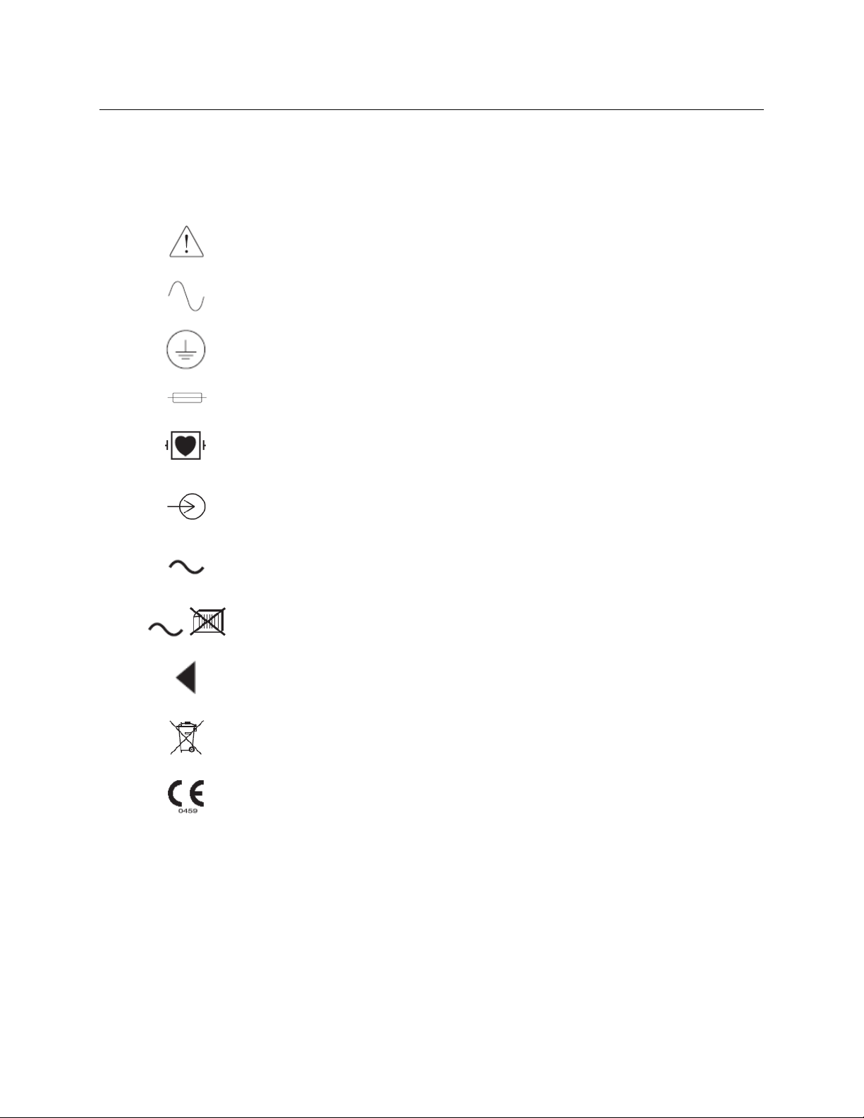
Symbol Delineation
Attention, consult accompanying documents
Alternating current
Protective earth
Fuse
Defibrillator-proof type CF applied part
Input
Green light illuminates when power is ON
Green light illuminates when paper is out or an error condition is detected
Advances paper to the next paper perforation and will reset a paper
error condition. When depressed for approximately 7 seconds, will
reset the device
Do not dispose as unsorted municipal waste. Per European Union
Directive 2002/96, requires separate handling for waste disposal according
to national requirements
Indicates compliance to applicable European Union directives
NOTE: Refer to the manual(s) accompanying the device that pertain to the computer hardware for
additional definitions of symbols that may be present.
viii
Page 11

ELECTROMAGNETIC COMPATIBILITY (EMC)
Electromagnetic compatibility with surrounding devices should be assessed when using the device.
An electronic device can either generate or receive electromagnetic interference. Testing for
electromagnetic compatibility (EMC) has been performed on the device according to the international
standard for EMC for medical devices (IEC 60601-1-2). This IEC standard has been adopted in Europe
as the European Norm (EN 60601-1-2).
The device should not be used adjacent to, or stacked on top of other equipment. If the device must be
used adjacent to or stacked on top of other equipment, verify that the device operates in an acceptable
manner in the configuration in which it will be used.
Fixed, portable, and mobile radio frequency communications equipment can affect the performance of
medical equipment. See Table X-4 for recommended separation distances between the radio equipment
and the device.
The use of accessories, transducers, and cables other than those specified by Mortara Instrument may
result in increased emissions or decreased immunity of the equipment.
ix
Page 12
ELECTROMAGNETIC COMPATIBILITY (EMC)
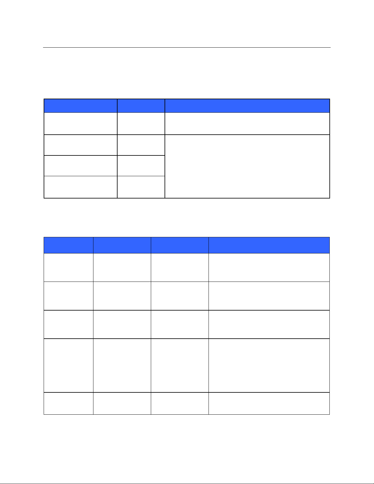
Table X-1 Guidance and Manufacturer’s Declaration: Electromagnetic Emissions
The equipment is intended for use in the electromagnetic environment specified in the table below. The
customer or the user of the equipment should ensure that it is used in such an environment.
Emissions Test Compliance Electromagnetic Environment: Guidance
RF Emissions CISPR 11 Group 1 The equipment uses RF energy only for its internal function.
Therefore, its RF emissions are very low and not likely to cause
any interference in nearby electronic equipment.
RF Emissions CISPR 11 Class A The equipment is suitable for use in all establishments other
than domestic and those directly connected to the public lowvoltage power supply network that supplies buildings used for
Harmonic Emissions
IEC 61000-3-2
Complies
domestic purposes.
Voltage Fluctuations/
Flicker Emissions
IEC 61000-3-3
Complies
Table X-2 Guidance and Manufacturer’s Declaration: Electromagnetic Immunity
The equipment is intended for use in the electromagnetic environment specified in the table below. The
customer or the user of the equipment should ensure that it is used in such an environment.
Emissions Test Compliance Compliance Level Electromagnetic Environment: Guidance
Electrostatic
discharge (ESD)
IEC 61000-4-2
Electrical fast
transient/burst
IEC 61000-4-4
Surge
IEC 61000-4-5
Voltage dips,
short
interruptions, and
voltage
variations on
power supply
input lines
IEC 61000-4-11
Power frequency
(50/60 Hz)
magnetic field
+/- 6 kV contact
+/- 8 kV air
+/- 2 kV for
power supply lines
+/- 1 kV for
input/output lines
+/- 1 kV differential
mode
+/- 2 kV common
mode
<5% UT
(>95% dip in UT)
for 0.5 cycle
40% UT
(60% dip in UT)
for 5 cycles
3 A/m 3 A/m Power frequency magnetic fields should be at
+/- 6 kV contact
+/- 8 kV air
+/- 2 kV for
power supply lines
+/- 1 kV for
input/output lines
+/- 1 kV differential
mode
+/- 2 kV common
mode
<5% UT
(>95% dip in UT)
for 0.5 cycle
40% UT
(60% dip in UT)
for 5 cycles
Floors should be wood, concrete, or ceramic
tile. If floors are covered with synthetic
material, the relative humidity should be at
least 30%.
Mains power quality should be that of a typical
commercial or hospital environment.
Mains power quality should be that of a typical
commercial or hospital environment.
Mains power quality should be that of a typical
commercial or hospital environment.
levels characteristic of a typical location in a
typical commercial or hospital environment.
NOTE: UT is the AC Mains voltage prior to application of the test level.
x
Page 13
ELECTROMAGNETIC COMPATIBILITY (EMC)
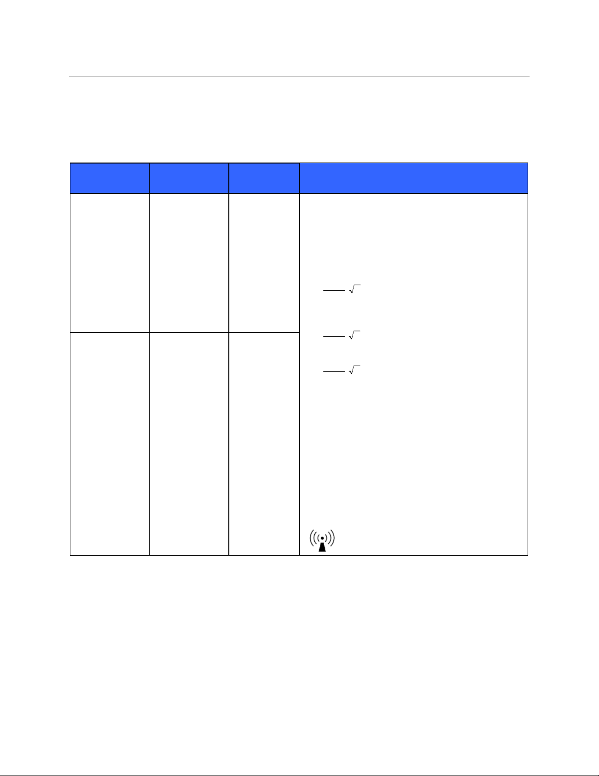
Table X-3 Guidance and Manufacturer’s Declaration: Electromagnetic Immunity
The equipment is intended for use in the electromagnetic environment specified in the table below. The
customer or the user of the equipment should ensure that it is used in such an environment.
Emissions Test
IEC 60601 Test
Level
Compliance
Level
Electromagnetic Environment: Guidance
Conducted RF
IEC 61000-4-6
Radiated RF
IEC 61000-4-3
3 Vrms
150 kHz to
80 MHz
3 V/m
80 MHz to
2.5 GHz
3 Vrms
150 kHz to
80 MHz
3 V/m
80 MHz to
2.5 GHz
Portable and mobile RF communications equipment
should be used no closer to any part of the equipment,
including cables, than the recommended separation
distance calculated from the equation applicable to the
frequency of the transmitter.
Recommended separation distance
5.3
⎤
⎡
d
=
⎢
Vrms
3
⎣
P
⎥
⎦
5.3
⎤
⎡
d
=
⎢
⎣
80 MHz to 800 MHz
P
⎥
mV
/3
⎦
7
⎤
⎡
d
=
⎢
⎣
Where P is the maximum output power rating of the
transmitter in watts (W) according to the transmitter
manufacturer and d is the recommended separation
distance in meters (m).
Field strengths from fixed RF transmitters, as
determined by an electromagnetic site survey
be less than the compliance level in each frequency
b
range
.
Interference may occur in the vicinity of equipment
marked with the following symbol:
800 MHz to 2.5 GHz
P
⎥
mV
/3
⎦
a
, should
a. Field strengths from fixed transmitters, such as base stations for radio (cellular/cordless) telephones
and land mobile radios, amateur radios, AM and FM radio broadcast, and TV broadcast cannot be
predicted theoretically with accuracy. To assess the electromagnetic environment due to fixed RF
transmitters, an electromagnetic site survey should be considered. If the measured field strength in
the location in which the equipment is used exceeds the applicable RF compliance level above, the
equipment should be observed to verify normal operation. If abnormal performance is observed,
additional measures may be necessary, such as reorienting or relocating the equipment.
b. Over the frequency range 150 kHz to 80 MHz, field strengths should be less than [3] V/m.
xi
Page 14
ELECTROMAGNETIC COMPATIBILITY (EMC)
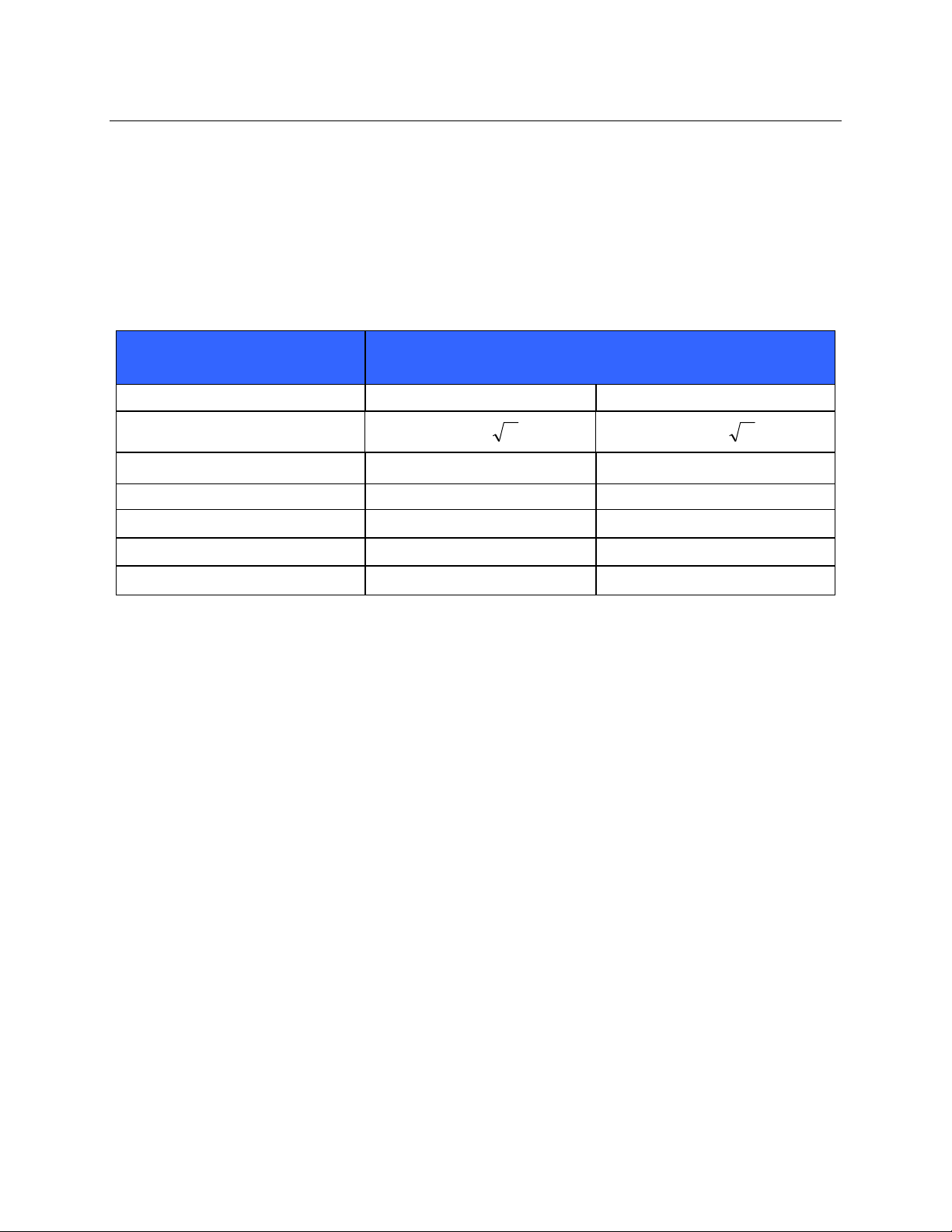
Table X-4 Recommended Separation Distances Between Portable and Mobile RF Communications
Equipment and the Equipment
The equipment is intended for use in the electromagnetic environment in which radiated RF disturbances
are controlled. The customer or the user of the equipment can help to prevent electromagnetic
interference by maintaining a minimum distance between portable and mobile RF communications
equipment (transmitters) and the equipment as recommended in the table below, according to the
maximum output power of the communications equipment.
Rated Maximum Output Power
of Transmitter W
150 KHz to 800 MHz 800 MHz to 2.5 GHz
Separation Distance According to Frequency of Transmitter (m)
0.01 0.1 m 0.2 m
0.1 0.4 m 0.7 m
1 1.2 m 2.3 m
10 4.0 m 7.0 m
100 12.0 m 23.0 m
Pd 2.1= Pd 3.2=
For transmitters rated at a maximum output power not listed above, the recommended separation
distance d in meters (m) can be estimated using the equation applicable to the frequency of the
transmitter, where P is the maximum output power rating of the transmitter in watts (W) according to the
transmitter manufacturer.
NOTE 1: At 800 MHz, the separation distance for the higher frequency range applies.
NOTE 2: These guidelines may not apply in all situations. Electromagnetic propagation is
affected by the absorption and reflection from structures, objects, and people.
xii
Page 15

TABLE OF CONTENTS
INTRODUCTION SECTION 1 1 - 14
MAINTENANCE & CLEANING SECTION 2 15 - 19
DEVICE CONFIGURATION SECTION 3 20 - 29
UNIT DISASSEMBLY SECTION 4 30 - 36
TROUBLESHOOTING SECTION 5 37 - 40
CONFORMANCE TESTING SECTION 6 41 - 43
COMMUNICATIONS OPTIONS SECTION 7 44
SYSTEM UTILITIES SECTION 8 45 - 49
BACKUP and RESTORE SECTION 9 50 - 53
xiii
Page 16

INTRODUCTION
SECTION 1
Manual Purpose
The purpose of this manual is to supply information to service personnel so they can maintain the
XScribe 5 System, information for peripheral devices should be found in manuals supplied with
equipment or by contacting original manufacturer. This manual is intended to function primarily as a guide
to preventative and corrective maintenance and electrical repairs considered field repairable.
NOTE: This manual may contain screen shots. Screen shots are provided for reference only
and are not intended to convey actual operating techniques. Consult the actual screen in the
host language for specific wording.
Periodic Safety Inspections
Follow the recommended maintenance schedule. Inspect the power cord and transmission cables
periodically for fraying or other damage and replace as needed. Broken or frayed wires may cause
interference or loss of signal.
Pay particular attention to points where wires enter connectors.
Proper Power Cord
The power cords from all the peripheral equipment should be plugged into the Isolation Transformer. This
product
requires a three-wire, (18 gauge, SJT-grade) power cord, which is supplied with a three-terminal,
polarized plug (hospital grade) for connection to the power source and protective ground. Use of the
Isolation Transformer supplied, is required. An interruption of the grounding connection could cause an
electrical shock hazard.
Proper Fuse
Applies to Isolation Transformer only. Use only the fuse specified for the equipment (identical in type,
voltage, and current rating). Substituting a different fuse type could cause a fire hazard. Always make
sure fuses have been installed before operating the equipment.
Do Not Operate in Explosive Atmospheres
Do not operate the X-Scribe 5 in the presence of flammable gasses or anesthetics, this environment
could cause an explosion. Refer to Operator's Manual Safety Information: Warning(s) and Caution(s).
Use Only Safe Methods of Interconnection
To prevent electrical shock from the product when it is connected to other electrical equipment, proper
grounding is essential. Refer to Operator's Manual Safety Information: Warning(s) Peripheral equipment.
Do Not Mount Product above Patient
Do not mount or place any part of the product where it could fall on a patient or where it could be
accidentally knocked off a shelf or other mounting arrangement.
Recommended Accessories
For the patient's safety and optimum equipment performance, use only the accessories specified by
Mortara Instrument, Inc.
1
Page 17

SECTION 1
System Description
The XScribe is a high-performance, PC-based, dedicated color, stress exercise testing system with an
exam database capable of acquiring, viewing, printing, and storing ECG, NIBP, and SpO
data. The
2
XScribe may be used with a treadmill, ergometer, or pharmacological form of testing. The device is
equipped with Mortara Instrument’s VERITAS™ resting ECG interpretation algorithm. This feature
enables the VERITAS algorithm to provide an over-reading physician with a silent second opinion through
diagnostic statements output on the supine and Mason-Likar ECG reports. The interpretive portion of the
ECG is available in the pre-exercise portion of the test. For additional information on the VERITAS
algorithm, please refer to the Physician’s Guide to VERITAS 7 Resting ECG Interpretation. (See Parts
and Accessories.)
The XScribe system can function as a standalone workstation or can be set up in a distributed
configuration where the database resides on a server supporting a number of networked client
workstations.
The XScribe Review software offers users with appropriate permissions at a networked location the ability
to schedule new exams when not linked to an external scheduling system, view full disclosure exams,
enter conclusions, and generate printed or electronic reports for completed exams.
The XScribe workstation includes:
• PC with keyboard and mouse
• X12+ transmitter
• M12A or AM12 for traditional wired connection
• 24” wide screen color monitor
• Isolation transformer
• ECG lead wires
• Carry case with belt
• Software
• System cart
Optional items include:
• High-speed laser printer
• Z200+ thermal array printer
• Treadmill
• Ergometer
• Multi-modality module for wireless RF transmitter with TTL and analog output
• Multi-modality module for wired M12A with TTL and analog output
• Programmable remote keypad
• Local area network (LAN)
• Integrated non-invasive blood pressure monitoring with or without SpO
2
Miscellaneous System Information
• XScribe is capable of supporting the following video resolutions: 1920 x 1080, and 1920 x 1200.
• XScribe is capable of supporting HP LaserJet printers with 600 dpi and PCL5 capabilities, and
Mortara Instrument’s Z200+ thermal printer.
• A supplied network isolation device must be installed between the PC and wall network plug.
This is to ensure compliance with IEC 60601-1-1 standard.
NOTE: No user-serviceable parts are inside. ANY modification to device may alter defibrillator protection. Any
modification to any part of device is to be performed by qualified service personnel only.
2
Page 18
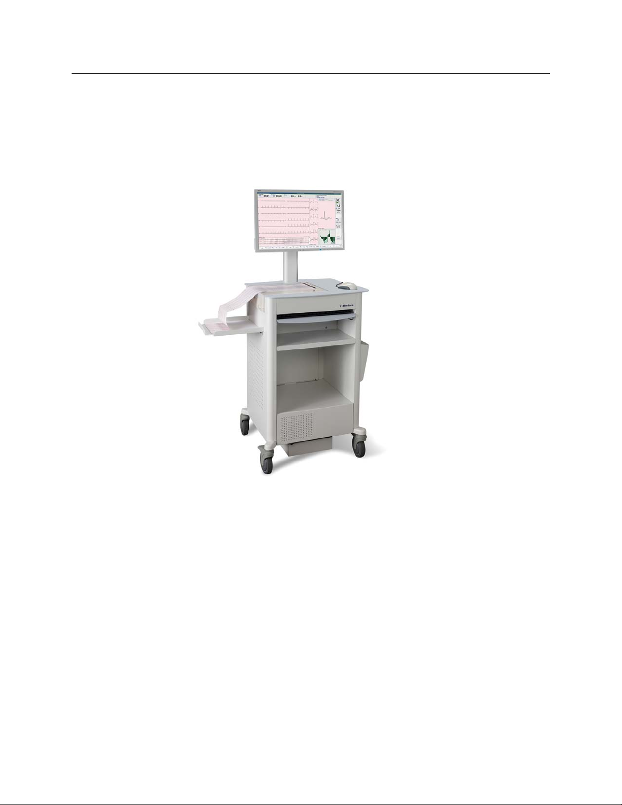
XScribe System*
Figure 1-1
SECTION 1
XScribe with Z200+ Thermal Writer and
Additional Storage Bin
3
Page 19
SECTION 1
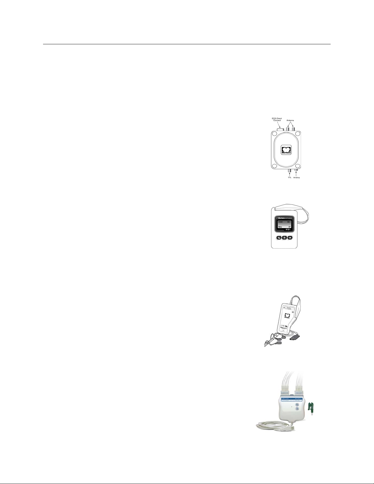
XScribe Front End Types
There are three front end types for patient connection that can be used with XScribe, two of which require
the use of the Multi-Modality Module.
Multi-modality Module (MMM)
MMM supports both X12+ wireless and M12A wired front ends with
TTL/Analog output, required for TANGO+ BP Monitor interface and ECG
signal output for echocardiographs and other devices. Antennas are
connected with 18” cables and must be at least 12” apart when installed
for the X12+.
X12+ Digital Transmitter
12-lead telemetry transmitter with Mortara’s patented LeadForm patient
cable operates in 608 MHz or 2500 MHz frequency. Uses one AA alkaline
battery for approximately 24-hours of continuous operation. Includes
impedance check and ECG display to ensure good quality patient hookup.
The RF Scan tool can be used with this front end for optimal channel
selection. Refer to the X12+ User Manual and short form instruction card
for detailed information.
M12A Patient Cable
12-lead patient cable together with Mortara’s patented LeadForm patient cable
for connection to MMM when a wired connection and TTL/analog output is
desired.
AM12 Patient Cable
AM12 for a traditional wired connection allows direct USB connection with
40,000 Hz ECG acquisition. LED for lead fail notification. Uses replaceable
lead wires with medi-clip connectors. Refer to the AM12 short form
instruction card for detailed information.
4
Page 20
XScribe Icon Descriptions
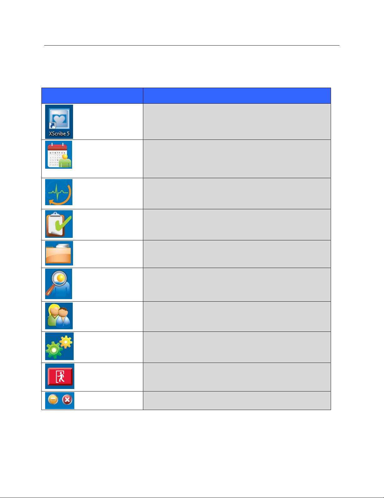
Icon and Hover Text Description
XScribe desktop shortcut icon to launch the Stress modality
application.
Opens a window allowing exam scheduling and schedule
review.
Schedule/Orders
Start a Stress Test
Worklist
This icon is only available when XScribe is not linked to an
external scheduling system.
Opens a window presenting scheduled exams or the Search
Patient list when no exams are scheduled allowing association of
patient demographic data with the exam. The stress hookup
display is opened when the Start Exam button is selected.
Opens a window displaying exams with a preset filter showing
only Acquired, Edited, or Reviewed status according to user
preference. Checkboxes in the window allow further filtering.
Opens a window allowing users to search for Stress exams in
the database using filters.
SECTION 1
Exam Search
Opens a window allowing users to search for patients in the
database using filters and editing of the patient demographics.
Patient Search
Opens a window for configuring the user preferences for the
Worklist and changing the password.
User Preferences
Opens a window for administrative users to configure the system
settings such as creating/modifying users, changing the XScribe
default settings and protocols, defining archive directories, and
System Configuration
Exit
so on.
Closes the XScribe application and returns the user to the
desktop.
Allows users to Minimize or Exit the application and return to the
desktop.
5
Page 21

XScribe Technical Specifications
Features Specifications*
SECTION 1
Operating System
Input Channels
Standard Leads Acquired
Display
Exercise Equipment Interface
Automatic Blood Pressure
Measurement Option
Remote Keypad Option
Remote Review Workstation
Option
Input Dynamic Range
Electrode Tolerance
Common Mode Rejection
Frequency Response
X12+/M12A Digital Sampling
Rate
AM12 Digital Sampling Rate
Microsoft® Windows™ 7 Professional 32-bit
Simultaneous acquisition of all 12 leads
I, II, III, aVR, aVL, aVF, V1, V2, V3, V4, V5, V6
24” flat panel color monitor with 1920 x 1080 resolution
Digital serial interface to treadmill or ergometer
Optional interface to external automatic BP device; SpO2 available on
certain devices
Optional remote keypad interface for operation of treadmill, printing of 12-lead
rhythm strip, or NIBP acquisition
Optional remote review workstation for review, printing, and editing of patient
test data acquired from XScribe system
Meets or exceeds the requirements of ANSI/AAMI EC11
10,000 s/sec/channel used for pacemaker spike detection; 500 s/sec/channel
used for recording and analysis
40,000 s/sec/channel used for pacemaker spike detection; 500 s/sec/channel
used for recording and analysis
Network Option
Device Classification
Printer Options
Data Acquisition
External Output
Power Requirements
Power Requirements for
Isolation Transformer
Power Requirements for
Optional Laser Printer
Power Requirements for
Optional Tango NIBP/SPO2
6
Optional network interface for data export and printing across local network
Class I, Type CF defibrillator-proof applied parts
High-speed LaserJet printer or thermal array with 200 dots per inch; network
print capability; electronic final report export local or via network.
Direct connection using Mortara’s AM12 or M12A patient cable; wireless
connection using Mortara’s X12+ transmitter
TTL and analog output
110-240 VAC at 50/60 Hz
1000VA rating; Maximum Current Input of 8.5A at 115V; Maximum Current
Input of 4.2A at 230V; Maximum four pieces of equipment connected at once
Maximum power draw of 800W
Input: 90-250 VAC at 47-63 Hz. Output : 9VDC
Page 22
XScribe Hardware Specifications
Feature XScribe Workstation Minimum Specifications*
CPU HP rp5800 model
Processor Intel Core i3
Operating System Microsoft Windows 7 32-bit Professional
Graphics 1920 x 1080
RAM 4 GB
Hard Drive Capacity 500 GB
Archive Network or external USB drive
Input devices USB Standard keyboard and scroll mouse
SECTION 1
Software Installation CD-ROM
Network 100 Mbps connection or better
Printing Devices HP M401n LaserJet printer (to fit in cart)
Z200+ thermal printer (requires additional network port)
USB ports 2 free USB 2.0 ports
Serial Ports 2 serial ports required for digital interface
Chassis H x W x D 3.95 x 13.3 x 14.9 inches
100 x 338 x 379 millimeters
Audio Required for NIBP and Pharmacological notification
Isolation Transformer Required When Workstation Is Used For Stress Testing
Isolation Transformer
Requirement
Known Agency Mark (KAM)
Meets IEC 60601-1 requirements
Protective Earth conductor for all connected equipment
Z200+ only configuration: 300 watts
LaserJet printer configuration: 1,000 watts
* Specifications subject to change without notice.
7
Page 23

Feature XScribe Server Minimum Specifications*
Processor Performance equivalent to an Intel Xeon class,
Quad-core with hyperthreading
Graphics 1024 x 768
RAM 4 GB
Operating System Microsoft® Windows™ 2008 server R2 Service Pack 1, 64-bit
(required)
System Disk 100 GB for OS and product installation
(RAID recommended for data redundancy)
Data Disks 550 GB hard drive space available
HD controller with 128 MB read/write cache
(RAID recommended for data redundancy)
Archive Network or external USB drive
Software Installation CD-ROM
SECTION 1
Network 100 Mbps connection or better
Input devices Standard keyboard and mouse
* Specifications subject to change without notice.
8
Page 24
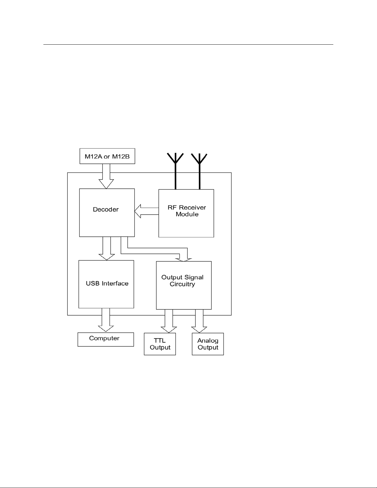
M12RFXXXX-USB Block Diagram
The M12RFXXXX-USB is the wireless version of the M12C-USB. This unit allows the use of the
X12 or X12+ Transmitter to input the ECG signal from the patient into the XScribe Stress System.
The M12RFXXXX-USB comes in two different version, the M12RF2500-USB for use with the X12
and X12+ 2500MHz transmitters and the M12RF608-USB for use with the X12+ 600MHz
transmitters. The design of the M12RFXXXX-USB is such that it will allow ECG input from either
a M12A or M12B or the X12 or X12+.
SECTION 1
9
Page 25
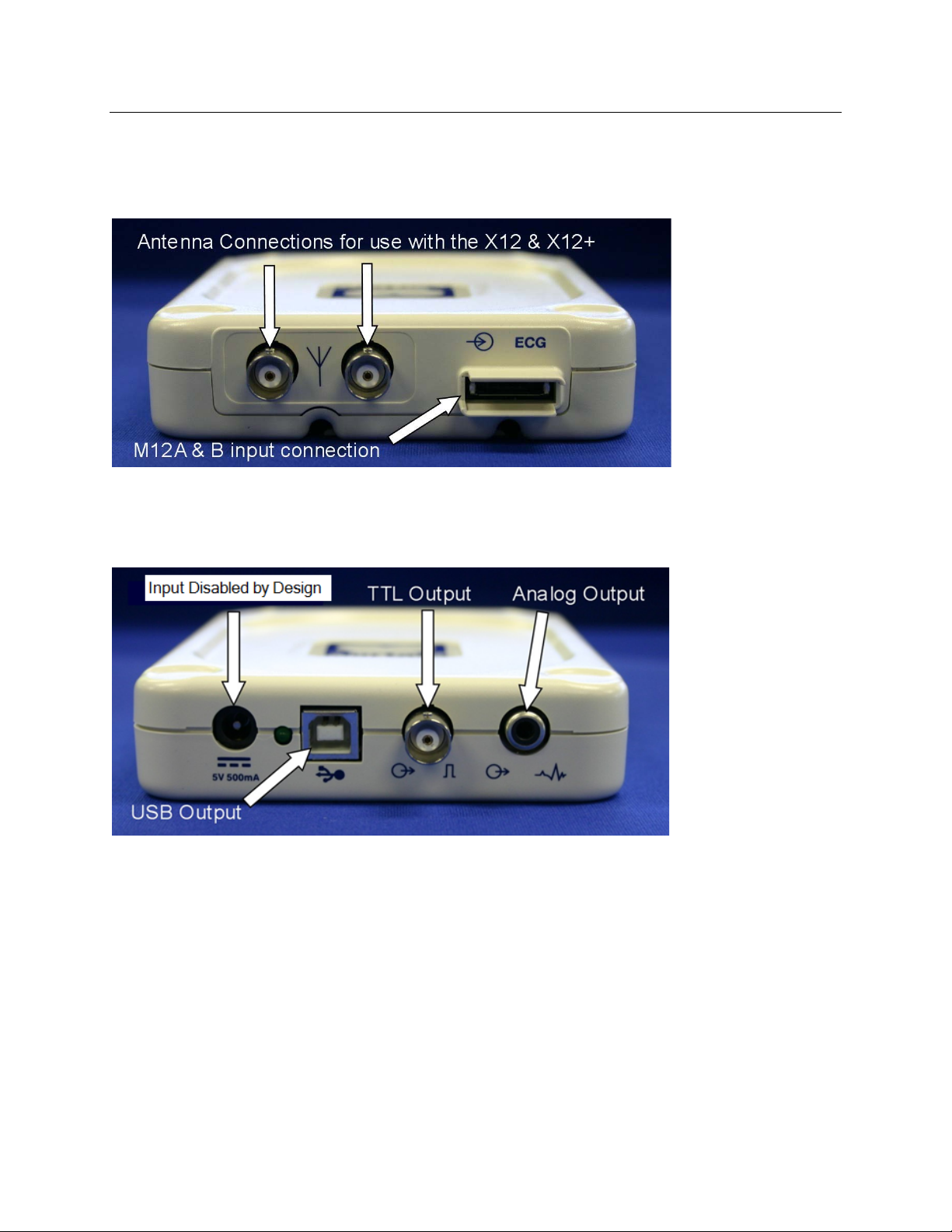
M12C-USB and M12RF-USB Input Connections
M12C-USB and M12RF-USB Output Connections
SECTION 1
Note: Devices connected to the TTL output and the Analog output of the M12C-USB and the M12RFUSB must be IEC60601-1 compliant.
10
Page 26
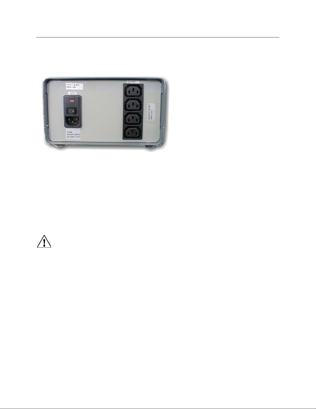
Medical Isolation Transformer
SECTION 1
Medical Isolation Transformer
Specification:
Frequency: 50/60 Hz
Output Ratings: 115/230V 1000VA
Weight: 22 lbs. (9.98 kg)
Dimensions: Height = 5.1” (130 mm)
Width = 8.0” (203 mm)
Depth = 11.0” (280 mm)
REF: 1404-002 Input 115VAC 50/60 Hz 2x10AT Fused
REF: 1404-003 Input 230VAC 50/60 Hz 2x6.3AT Fused
CAUTION: Before connecting system components to the isolation transformer, ensure the
voltage selector (located above the power cord) matches the line voltage.
CAUTION: Risk of electrical shock. Do not remove cover. Refer servicing to qualified
service personnel. Grounding reliability can only be achieved when system components are
connected to an equivalent receptacle marked “hospital grade.”
CAUTION: Use of this transformer with equipment other than originally supplied, or
surpassing the ratings, may cause damage, fire, or injury.
WARNING: Possible explosion hazard. Do not use in the presence of flammable
anesthetics.
11
Page 27
SECTION 1
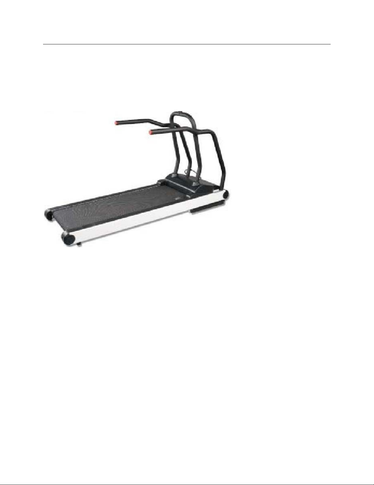
Treadmill
The treadmill models currently used with the Scribe 5 Stress test system are Full-Vision TrackMaster
TMX-425 or FVX-328.
Please refer to the treadmill owner’s manual that came with the treadmill for maintenance information.
*Note – The treadmill MUST be connected to a dedicated mains outlet.
12
Page 28
SECTION 1
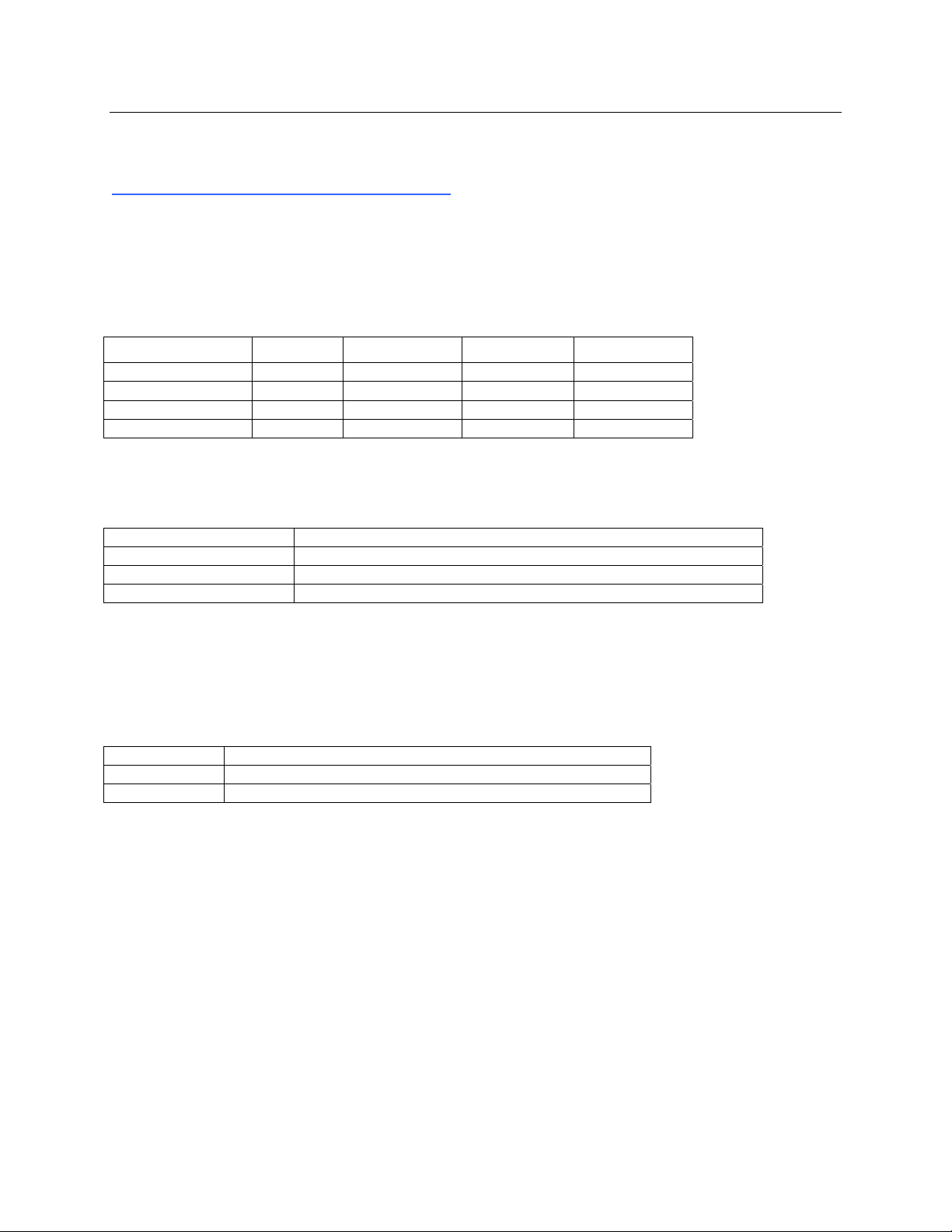
Historical Reference Tables:
Patient Cable Input to Computer Input Compatibility
The following table shows compatibility of the above computer input devices.
Computer Input Device
Patient Cable Input M12C-USB M12RF2500-USB M12RF600-USB CPU USB Port
M12A
X12 2500
X12+ 2500
X12+ 608
Computer Input to Computer Operating Systems Compatibility
Computer Input Device Operating system(s)
M12RF2500-USB Windows XP SP2 (Service Pack 2 and above), Windows 7 32-bit
M12RF600-USB Windows XP SP2 (Service Pack 2 and above), Windows 7 32-bit
M12C-USB Windows XP SP2 (Service Pack 2 and above), Windows 7 32-bit
Printer Compatibility to Operating System Compatibility
The following table lists compatibility of the Z200 and Z200+ Thermal Printers with the operating systems.
Printer Operating System(s)
Z200+ Windows 98, 2000, XP, Windows 7 32-bit
Laser Printer* Windows 95, 98, 2000, XP, Windows 7 32-bit
* Laser Printer: Any laser printer supported by the Windows Operating System should work properly. It is
however recommended to test any printer before making a final standard decision. Please note that
compatible printers will differ in the printing speed and this may affect the continuous printout function
offered by the system. The HP 1100 is considered the low-end printer type and it barely allows
continuous printouts. The HP 4000 series are high-speed printers and allow continuous printouts.
Yes Yes Yes -
- Yes - -
- Yes - -
- - Yes -
13
Page 29

SECTION 1
XScribe 5 Output Signals
The following table describes the output signals that the XScribe system can produce for interfacing to
other devices.
Scribe 5 computer input
device
M12C-USB TTL
M12RF-USB TTL
Output
signal
Analog
Analog
Method of connection to external
device
BNC connector on M12C-USB
RCA connector on M12C-USB
BNC connector on M12C-USB
RCA connector on M12C-USB
XScribe 5 Software Version Compatibility with Operating System
XScribe Software Version Operating System
XScribe 5 Version Windows 7 32-bit
XScribe 5 Software / USB Driver Information
XScribe Software Version Supplied Driver M12C/M12RF-USB
XScribe 5.xx 2.00.01 Yes
14
Page 30

MAINTENANCE & CLEANING
Warning: Preventive maintenance is to be performed by Mortara authorized service
personnel only.
Maintenance Procedure
Mortara recommends device maintenance is performed on an annual basis.
Equipment needed:
• Treadmill PM KIT
• 1/4" Nut Driver
• 3/8" Allen Wrench
• 1/4" T-style Allen Wrench
• 1/2" Combination Wrench
• Tube of TrackMaster Grease (or equivalent)
• RS-232 Treadmill Test Plug
• Treadmill Test Program
• Clean, lint-free cloth
• Cleaning solvent (isopropyl alcohol, 70% pure)
• DRY, low pressure, compressed air (30 psi)
• Masking tape
• Rubber Rejuvenator/Platen Cleaner
• Screwdriver Philips #2
• Safety Analyzer
SECTION 2
Treadmill Preventive Maintenance
Refer to the service manual for the treadmill model utilized with the XScribe system for
preventive maintenance information. The following list of activities should be performed to
properly maintain and verify proper treadmill operation.
Treadmill Inspection/Maintenance:
• Running Belt Cleaning & Inspection
• Running Belt Tension Check/Adjustment
• Drive Belt Tension Check/Adjustment
• Elevation Screw Lubrication
• Control Cable Fastened/Routed Appropriately
Treadmill Functional Testing
• Test Plug Operation
• XScribe Control Test
• Emergency Stop Button Check
15
Page 31

MAINTENANCE & CLEANING
SECTION 2
XScribe System Preventive Maintenance and Cleaning
Mounting of Antennas / Receiver Module / Direct Connect Module
Verify that the system antennas, receiver module, and/or direct connect module are properly
mounted or located on the XScribe cart for optimum performance. The cables and positioning of
these devices should be such that they do not interfere with the operator of the system, and do
not cause a potential hazard to anyone who is walking nearby or around the system. In the case
of the direct connect module, a strain relief should be provided to prevent the USB cable
connector from being damaged due to accidental tension being applied to the cable from the
module to the PC.
System PC Cleaning
Remove and open the system PC from the transport cart. Using a vacuum or compressed air,
remove any accumulated dust and debris from the PC. Take particular care to cleaning around
cooling fans and inside media access slots (refer to cooling fan inspection below). Clean the cart
area that the PC and peripheral equipment reside in, to prevent dust and debris accumulation
from occurring. Reinstall the PC into the transport cart once completed.
Inspection of PC cooling fans
Inspect CPU fan, and power supply fan. If they are running too slowly or are making any
unusual noises during operation, they should be replaced. For improperly operating PC
power supply fans, Mortara recommends replacing the entire power supply unit.
Monitor Cleaning
WARNING: To avoid risk of electric shock and damage to the monitor, do not
disassemble the monitor cabinet. The unit is not user-serviceable. User maintenance is
restricted to the following cleaning instructions.
Unplug the monitor from the power outlet before cleaning.
• To clean your monitor screen, lightly dampen a soft, clean cloth with water or mild
detergent. If possible, use a special screen cleaning tissue or solution suitable for the
anti-static coating.
• To clean the monitor cabinet, use a cloth lightly dampened with mild detergent. Make
sure that water cannot drip into the case of the monitor.
• Wipe off stubborn stains from the cabinet or screen with a cloth lightly dampened in
isopropyl alcohol. Do not use benzene, thinner, ammonia, or abrasive cleaners.
Keyboard/Mouse Cleaning
Turn the keyboard upside down. Gently tap the back of the keyboard and press the keys to
release any debris from in between the keys.
16
Page 32

MAINTENANCE & CLEANING
SECTION 2
If you have a can of compressed air then use it to blow any debris from around and under the
keys, if not then use the hose of a vacuum cleaner to remove it.
If the keys appear to need cleaning, use a cotton swab with isopropyl alcohol on it to clean the
sides of the keys as needed.
After cleaning the sides of the keys take your lint free cloth and dampen it with isopropyl alcohol
(don't put the liquid directly on the keyboard), give the surface of the keyboard a good wipe over
using the cloth to trace the contours of the keys. Use the damp cloth to gently wipe the mouse to
remove any hand oils or debris that may be present.
XScribe Cart Cleaning
Use a damp, clean cloth to wipe off external surfaces with isopropyl alcohol. Do not use solvents,
or cleaning solutions that may damage the surface of the instrument. Avoid contact with open
vents, plugs, and jacks.
Cable Management
Arrange the PC interconnect cables in an orderly manner to prevent any of the cables from
becoming stressed or dislodged over time. Cable ties and/or fasteners can be used to manage
systems that have a significant amount of interconnecting cables to the PC and isolation
transformer.
Thermal Writer Cleaning
Use a damp, clean cloth to wipe off external surfaces. Open the writer door and use masking tape
to clean the platen of the thermal writer. The platen should then be further cleaned with a Rubber
Rejuvenator/Platen Cleaner to ensure it does not deteriorate over time. The thermal print head
can be cleaned using a clean lint free cloth and isopropyl alcohol; simply wipe the print head
surface that makes contact with the paper to remove any debris or residue that may have built up
during operation.
System Checks
Archive Management
With customer’s assistance, create additional Archive folders on the root directory or on
the network (if option installed). Refer to the X-Scribe User Manual (9515-151-50-ENG)
for complete instructions. Archive all the patient exams from the root Archive to the newly
created Archive locations.
Hard Drive Space
Check the capacity of the system hard drive to ensure there is sufficient space for system
operation. If the system drive is nearing capacity (approaching 90%), this issue should be
discussed with the facility to create additional space for proper operation. If the drive was
near capacity and unnecessary files were removed, a defragmentation may be performed
to ensure optimal performance of the drive.
Note: The defragmentation process may take several hours and is only required in extreme cases.
17
Page 33

MAINTENANCE & CLEANING
Z200+ Writer Test
Using the Z200Plus Monitor software, print off a test page. The Z200PlusMonitor
software can be loaded onto the XScribe system or ran from USB stick. Double click
Z200PlusMonitor icon to launch the application. Press Connect and then press Print Test
Page. Verify on the print out page that there are no missing pixels or light printing. Now
press Disconnect and close the application.
Conformance Testing
Transmitter(s) and Patient Cable(s)
Verify patient cable connector pins are not bent by disconnecting patient cable from
transmitter and observing. Connect transmitter to a patient simulator. Then perform a
lead check as described in X12+ User Manual (9515-164-50-ENG) or T12 User Manual
(9515-173-50-ENG). Wiggle patient cable to verify lead wires are not broken.
Stress Test
Connect a patient simulator to the transmitter. Start a New Exam and let the system go
through a complete Bruce protocol test. Verify that treadmill speed and elevation increase
with each stage. Verify that printouts are coming out the Z200+ writer. Verify you do not
see any square waves on the display of the XScribe system.
Data Export (if option installed)
Verify XScribe is able to Export pdf’s, xml. tif, DICOM, etc to the network. Verify XScribe
is able to download a worklist from the network.
Safety Testing
The following safety tests should be performed in accordance with IEC 60601 or IEC 62353
standards and all local regulatory requirements:
• Earth Leakage (performed on medical isolation transformer)
• Enclosure Leakage (performed on medical isolation transformer)
The following safety tests are required only for systems utilizing a wired patient interface.
• Patient Leakage
• Patient Leakage Type-F
• Patient Auxiliary Current
SECTION 2
18
Page 34

MAINTENANCE & CLEANING
Mortara Instrument Inc.
XScribe Preventive Maintenance Report
XScribe Serial #: _________________________________________
Treadmill Serial #: _________________________________________
□ Treadmill Inspection / Maintenance
□ Running Belt Cleaning & Inspection
□ Running Belt Tension Check / Adjustment
□ Drive Belt Tension Check / Adjustment
□ Elevation Screw Lubrication
□ Control Cable Fastened/Routed Appropriately
□ Treadmill Functional Testing
□ Test Plug Operation
□ X-Scribe Control Test
□ Emergency Stop Button Check
_____________________________________________________________________________
□ Visual Inspection/Cleaning
□ Verify antennas or direct connect module are properly mounted
□ Inspect/Clean system PC, monitor, keyboard and mouse
□ Inspect/Clean any adhesive residue or scuff marks from transport cart
□ Organize/fasten interconnect cables on cart
□ Thermal Writer Cleaning (if option installed)
□ Platen Cleaning
□ Thermal Printhead Cleaning
□ System Checks
□ Archive management
□ Sufficient hard drive space
□ Print writer test page and inspect for proper operation/darkness
□ Conformance Testing
□ Perform lead check on system transmitter(s) and patient cable(s)
□ Perform a full stress test with a patient simulator
□ Verify treadmill turns on as per protocol settings
□ Verify writer prints as per protocol settings
□ Verify data export functionality (if option installed)
□ Safety Testing
□ Earth Leakage
□ Transformer Enclosure Leakage
(The following tests are performed for wired patient inputs only)
□ Patient Leakage
□ Patient Leakage Type-F
□ Patient Auxiliary Current
Technician or Field Service Engineer: ________________________________ Date: _____/_____/_____
SECTION 2
Mortara Instrument, Inc. Phone (414) 354-1600
7865 N. 86th Street Fax (414) 354-4760
Milwaukee, WI. 53224
19
Page 35
DEVICE CONFIGURATION
Administrative Tasks
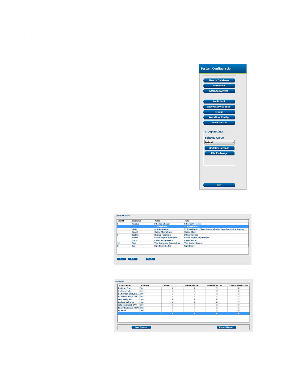
The IT and Clinical Administrator user will select the System Configuration
icon to enter the XScribe administrative functions. All other users can enter
this menu to access the Export Service Log task only.
A list of administrative tasks is presented to:
• Manage user accounts
• Manage personnel lists
• Manage Groups
• Manage archived exams*
• View audit trail logs
• Export service logs for troubleshooting purposes
• Configure system-wide modality settings
• Configure DICOM data exchange
• Configure XML and PDF data exchange
• Configure workflow
• Unlock exams
SECTION 3
* Task may not be available when operating with DICOM.
Manage User Accounts
User’s Database
The IT administrator will select
User’s Database to create or
remove user accounts, reset user
passwords, assign permissions for
each user, and assign personnel
entries for that user’s selection.
When a single sign-on is used, no
user account and password creation
is needed.
Personnel
Personnel is selected to add
personnel that will be available in
the Patient Information, Summary,
and the Finalize Exam Update
windows. Listed personnel can be
assigned to each user account and
will appear as selections for the
logged-in user and in the
appropriate final report fields.
20
Page 36
SECTION 3
Manage/Create Groups
Groups allow the administrator to group exams according to reporting preferences (modality settings) and
file exchange preferences. A single default group exists that can be copied and saved with a new name to
create a second group. Select Groups to make a change. Any created group can be copied, renamed
and modified. The Default group can be renamed. An unlimited number of groups can be created and
modified.
XScribe Modality Settings and File Exchange paths can be uniquely defined for each individual group.
Groups, with exception of the Default group, can be deleted resulting in deletion of all exams that exist
within the deleted group.
Modality Settings
XScribe modality settings are defined as default by the clinical administrator and are available for the user
with editing permissions. The user is able to modify these settings on a per exam basis. Select the tab
you wish to modify and click on Save Changes or Discard Changes to cancel changes before exiting.
Profile
The Profile for the factory default group can be modified according to physician and user preferences. A
single profile that contains four tabs, described below and on the following page, is defined per group.
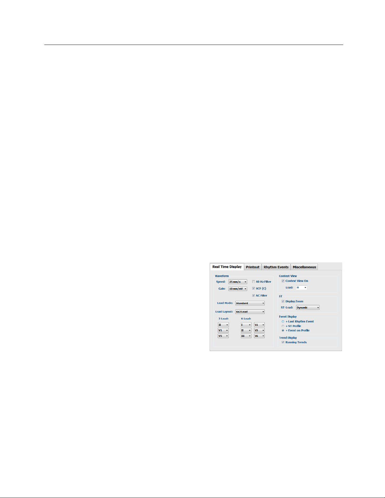
Real Time Display
Use the drop-down lists to select the Waveform speed,
gain, Lead Layout, Lead Mode and 3 or 6 leads for
display.
40 Hz, Source Consistency (SCF©), and AC filters are
enabled by check box.
Choose the Context View On check box to enable and
select the default lead from the drop-down list.
Standard or Cabrera lead mode can be selected.
Enable ST-Lead by checkbox and use the drop-down
list to select the default for the 4x QRS window. When
Dynamic is selected, the lead with the most significant
ST change is displayed.
Choose the desired radio button for the Event Display.
When the Trend Display is enabled, the HR, METs,
NIBP, and ST running trends are displayed during the
test.
21
Page 37
Printout
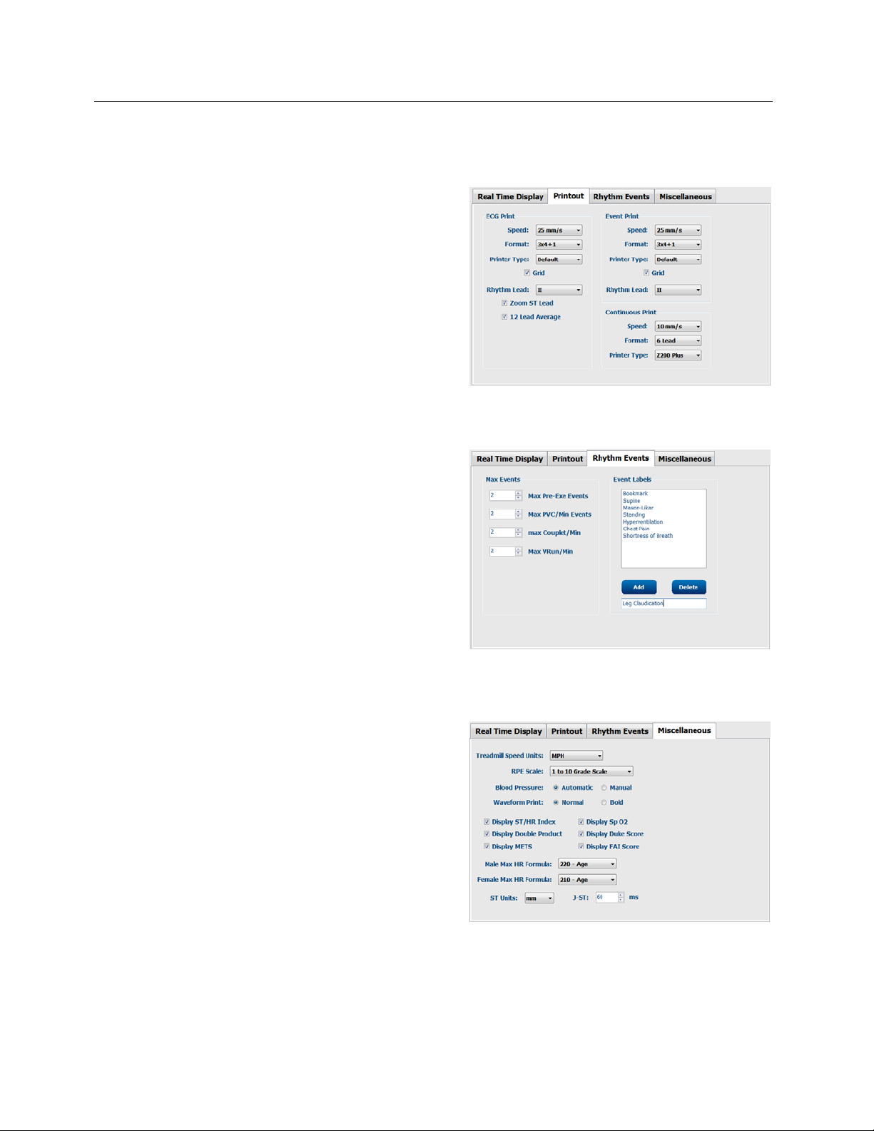
Use the drop-down lists to select the ECG Print Speed,
Format, and Printer Type for 12-lead ECG printouts.
Grid can be enabled for windows printers. Choose the
Rhythm Lead from the drop down and enable Zoom ST
Lead and 12 Lead Average as desired.
Use the drop-down lists to select the Event Print Speed,
Format, and Printer Type. Grid can be enabled for
windows printers. Choose the Rhythm Lead from the
drop down.
Use the drop-down lists to select the Continuous Print
Speed, Format, and Printer Type for 12-lead ECG
printouts.
Rhythm Events
Use the up/down arrows to select the maximum number
of events stored during pre-exercise and PVCs per
minute events, maximum couplets per minute, and
maximum ventricular runs per minute during exercise.
SECTION 3
Use Add or Delete to modify the Event Labels list.
NOTE: Bookmark, Supine, Mason-Likar, Standing, and
Hyperventilation event labels are listed by default and
cannot be edited or deleted.
NOTE: XScribe automatically detects an arrhythmia
event. It is stored, can be displayed on trends display,
and printed if Arrhythmia Printouts is enabled in the
Softkey pop-up menu.
Miscellaneous
Use the drop-down lists to select the Treadmill Speed
Units and RPE Scale type.
Choose Automatic or Manual Blood Pressure radio
buttons.
Choose Normal or Bold Waveform Print.
Use checkboxes to enable display of ST/HR Index,
Double Product, METS, SpO2, Duke Score and FAI
Score.
Use drop-down lists to select Male Max HR formula,
Female Max HR formula, and ST Units in mm or μV.
Use up/down arrows to choose ST post-J measurement
in milliseconds.
22
Page 38
SECTION 3
Protocols
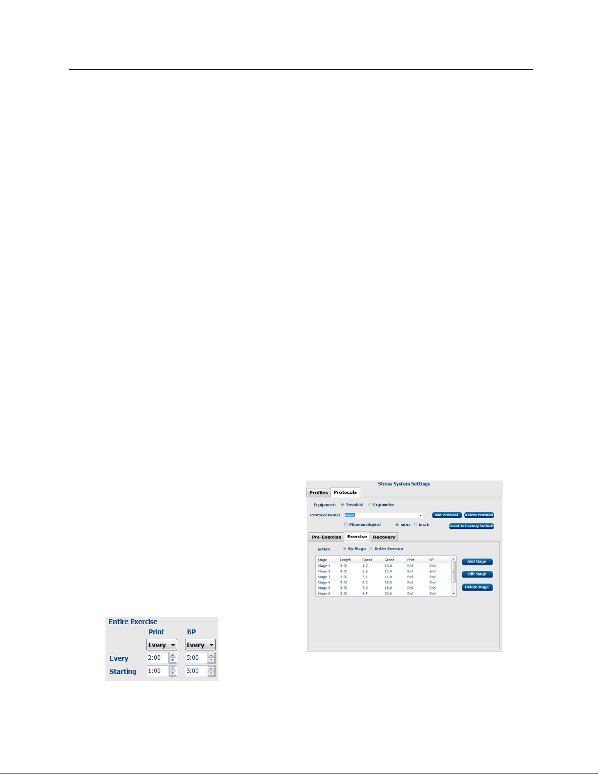
Users can Add Protocol to create a copy of the selected protocol, Delete Protocol and Reset to Factory
Default. The Add Protocol button will create a copy of the selected protocol that can be edited and
renamed. All added protocols will be deleted by selection of the Reset to Factory Default button.
The Protocols tab selections are related to each selected Protocol Name. Choose from the Protocol Name
drop-down list to edit the stage settings for that protocol. Select the Save Changes button prior to exiting,
or the Discard Changes button to cancel your edits.
Protocol Name — Use the drop-down menu to select a specific protocol.
Equipment — Displays the exercise equipment associated with the selected protocol.
Pharmacological — A dose setting is included that when selected prompts the system to display a
pop-up window notifying the clinician that a next-dose administration may be required.
Add Protocol — Adds an additional protocol requiring the user to complete fields on the 3 tabs: PreExercise, Exercise, and Recovery.
• Type a name for the new protocol
• Select the equipment associated with the new protocol
NOTE: Refer to your treadmill/ergometer documentation to check models supported by XScribe,
or contact Mortara Technical Support for assistance.
Pre-Exercise
• Speed/Grade or Power: use the up/down arrows to define treadmill speed and grade, or ergometer
power in watts.
Exercise
• Use the Add Stage to define the number of
exercise stages needed. A maximum of 60
stages at a maximum stage time of 30 minutes
per stage and a minimum stage time of 15
seconds per stage may be defined for each
protocol.
• Select the Action to define ECG Print, BP
measurement, and Dose By Stage or for the
Entire Exercise starting at mm:ss every
mm:ss independent of stage durations.
23
Page 39
SECTION 3
To define a stage, highlight and click Edit Stage.
• Time/Speed/Grade or Power: use the up/down arrows to define stage length, and treadmill
speed/grade, or ergometer power in watts.
- set Time in increments of five seconds, starting at 10 seconds.
- set treadmill speed from 0.0 to 12.0 mph, and 0.0 to 19.3 kph.
- set treadmill grade from 0° to 25° elevation.
- set ergometer power starting at 10 watts.
• ECG Print/BP Measure: use the drop-down menus to define when to print an ECG and/or prompt for a
blood pressure reading.
- to print/prompt at the beginning of a stage, select Begin.
- to print/prompt at the end of a stage, select End.
- select Off for no print/prompt.
- select Every to manually define the print/prompt time. Use the upper portion of the time selection to
define frequency; use the lower portion to define when.
• Dose: use the drop-down menu to define when to administer the next pharmacological stage.
Settings available are the same as for ECG Print/BP Measure above.
NOTE: When using a device to acquire a BP measurement at the beginning of a stage, XScribe
will start BP acquisition immediately upon stage start. When acquiring a BP measu rement at the
end of a stage,
XScribe will start acquisition one minute before stage end enabling the BP measurement to be
printed on the ECG printout. If XScribe does not receive the BP measurement within the oneminute time period, the BP measurement will not appear on the ECG printout.
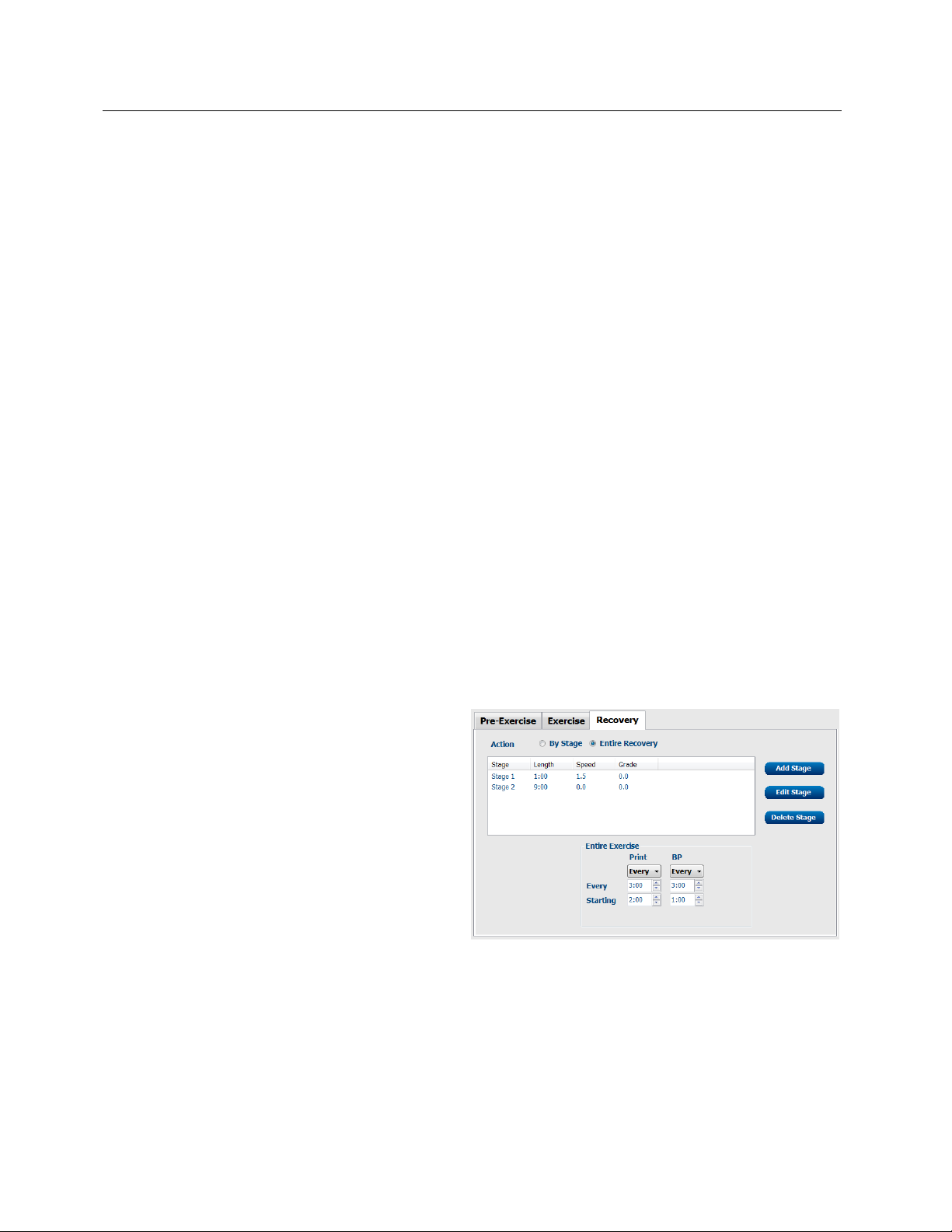
Recovery
• Number of Stages: use the up/down arrows to
define the number of recovery stages needed.
A maximum of 60 stages at a maximum stage
time of 30 minutes per stage and a minimum
stage time of 15 seconds per stage may be
defined for each protocol.
Define individual stages in the same manner as for
Exercise.
24
Page 40

SECTION 3
File Exchange
XScribe supports the ability to import orders from XML files and export PDF and XML results to an external
system dependent on the system activated features. Import/Export directories for the selected group are
defined in the File Exchange window. The Site Number field is not applicable to XScribe. Refer to the
Scribe Data Exchange Administrator Manual (P/N: 9515-185-51-ENG) for external system integration
details.
PDF File Name
The final report PDF file name will have the following structure:
X^<FileType>_EXMGR^<Group>_<PatID>^<LName>^<FName>^<MName>_
<TestDateTime>_<ReportDateTime>.XML
DICOM Settings
XScribe supports the ability to exchange information with DICOM systems dependent on the system
activated features. A DICOM Modality Worklist (MWL) will be received from the DICOM server. A DICOM
encapsulated PDF will be exported to the defined destination. Refer to the Scribe Data Exchange
Administrator Manual (P/N: 9515-185-51-ENG) for DICOM connectivity configuration details.
Unlock Exams
XScribe internally tracks transitioning exams preventing the same exam to be processed by two or more
users. When a second user attempts to access an exam in use, a message displays with notification that
the exam is not currently available.
As a measure for recovering locked exams, administrative users can unlock an exam that resides on the
same workstation by selecting Unlock Exams. Highlight the listed exam(s) and click on Unlock.
Manage Archive Storage
The XScribe administrative user will manage storage system disks through selection of Storage System.
Add Archive Location
Select Mount Remote Disk to open a window allowing entry of a path to the archive directory destination.
Any external disk (e.g. NAS, USB, etc.) accessible from the XScribe central database is a candidate for
becoming an archive volume. A Username, Password and Domain must be entered to Add the new
storage disk to the Available Disks listing. Select Cancel button to exit this window without saving
changes.
Restore Archived Exams
Administrative users can restore exams from the archive location to the XScribe database through selection
of Archive Recovery. Once selected, a window will open listing exam archive date and time, archive name,
volume name, volume ID, and drive letter of the archive volume. To restore exams, highlight the desired
exam(s) in the list and click on Recovery. Multiple exams can be restored by highlighting them and then a
single Recovery button click.
Search can be used to find exams matching alphanumeric text entry. Column headers can be selected to
sort listed exams by that item.
25
Page 41

SECTION 3
Audit Trail Logs
The XScribe administrative user will select Audit Trail to view the audit trail history. A selection of filter
criteria is available to sort the listing by date, user, workstation, operation, or target (e.g. User, Patient,
Exam, Conclusion, Locked Exams, User and System Settings). One or two filter criteria can be used to
find audit trails.
Selection of results will display the differences by comparing the XML statistics data before and after
changes. A legend with colored highlighting will point to added, removed, changed, and moved
information.
All configuration information, user information, patient demographic information, exam demographic
information, textual conclusions, archive operations, and exam download requests are tracked by the audit
trail.
Service Logs
All XScribe users have access to Export Service Logs. Selection of the button creates a Win-7 zipped
file that can be sent to the desktop containing a copy of the system logged events.
The file named EMSysLog.xml.gz can be e-mailed to a Mortara service representative for troubleshooting
purposes.
Configure Workflow
The XScribe exam states are designed to follow typical user workflow. There are five possibilities with
meanings defined below each state:
1. ORDERED
The stress exam is either scheduled by a user or an external scheduling system has sent an order.
2. ACQUIRED
The stress exam is completed at the XScribe system and is ready for editing.
3. EDITED
The stress exam has been analyzed with or without changes and is ready for review by a
physician. Conclusions may be entered at this state.
4. REVIEWED
The stress exam has been reviewed and confirmed to be accurate by an authorized user (e.g.
physician, fellow, clinician, etc.). Conclusions may be entered at this state.
5. SIGNED
The exam is reviewed and electronically signed by an authorized user. No further workflow
processing is required. Conclusions may be entered at this state.
The user with appropriate permissions is prompted with a Final Exam Update dialog to confirm or Update
the next logical state when exiting a stress exam. A drop-down menu allows selection of a state in respect
to the exam’s current state. Cancel may be selected to discard any change to the state.
26
Page 42

SECTION 3
Workflow Config
A Legal Signature can be enabled by selecting Yes or
disabled by selecting No.
the workflow to include all, or exclude some states through
selection of Workflow Config.
• Select All under Modality Status to enable all six states.
• Select No REVIEWED under Modality Status to move the state from EDITED to SIGNED.
• Select No EDITED/REVIEWED under Modality Status to move the state from ACQUIRED to
SIGNED.
About the Legal Signature
The legal signature requires the user credentials prior to updating a stress exam when changing to a
signed state. When enabled, the user is prompted to authenticate with a user name and password when
transitioning to the signed state. Authentication can be entered when a different user is currently logged
in. When the correct credentials are not entered, the user will be notified with a message that the
“Credentials supplied are not valid.”
When the signing physician has been set up as an Attending Physician under Personnel, the printed name
will appear in the XScribe final report on the signature line following the “Signed By:” field label.
User Preferences
Select the User Preferences icon to open the window. Set selections define the default criteria for the
Worklist when the particular user is logged into XScribe. Set selections can be changed when the user
enters the Worklist window. The user can also change the password in this window when the system is
not set up with a single sign-on.
All users have access to the User Preferences settings but may not have the Worklist available. Those
users will only enter this window to change their own password.
There are three possible choices for the Worklist stress exam states that can be enabled or disabled by
checkboxes. The choices are dependent on the workflow configuration modality status setting in that
Edited or Review may not appear as selections.
1. Acquired
2. Edited
3. Reviewed
There are three choices for a default time filter.
1. All
2. Today
3. Today, Yesterday and Tomorrow
When finished, select OK to save changes or Cancel to exit the window without saving changes.
XScribe will present the default settings on any of the workstations that the user logs into.
Administrative users can configure
27
Page 43
SECTION 3
Report Configuration Tool
XScribe final reports should be configured with the practice name prior to using the system. The default
sections for final report inclusion are also customizable within this tool.
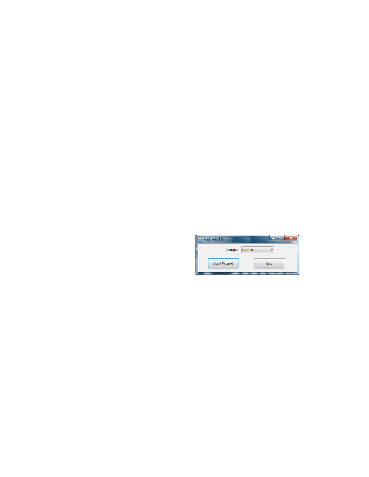
Click on the XScribe workstation Start menu. Choose All Programs, Mortara Instrument, Inc. followed
by Report Configuration Tool to open a dialog window prompting a Group choice from a drop-down list.
Each group that has been defined will have its own report configuration.
Click on the Start Wizard button to open the tool. The Exit button will close the tool.
Configuring the Final Report
Once the tool is opened, the following can be performed:
1. Hide final report sections by checkbox selection in the Report Configuration Tool. When the box is
checked, the section is disabled as a default; however, the section can be enabled for printing and
export when previewing the final report for each individual exam.
2. Enter institution contact information under the Practice section.
When finished, click on Next > and then Finish. <Back allows you to return to the previous screen;
Cancel prompts you with an “Are You Sure” message. Select Yes to cancel the changes.
Once finished, the Group selection is still available for
you to choose the next group to repeat the steps listed
above. When done defining all groups, select the Exit
button.
28
Page 44
SECTION 3
RF Scan for X12+
To reduce the possibility of radio frequency (RF) interference while using the X12+ wireless option, you
can use the XScribe to perform an RF Scan for optimal channel selection.
Click on the XScribe workstation Start menu. Choose All Programs, Mortara Modality Manager
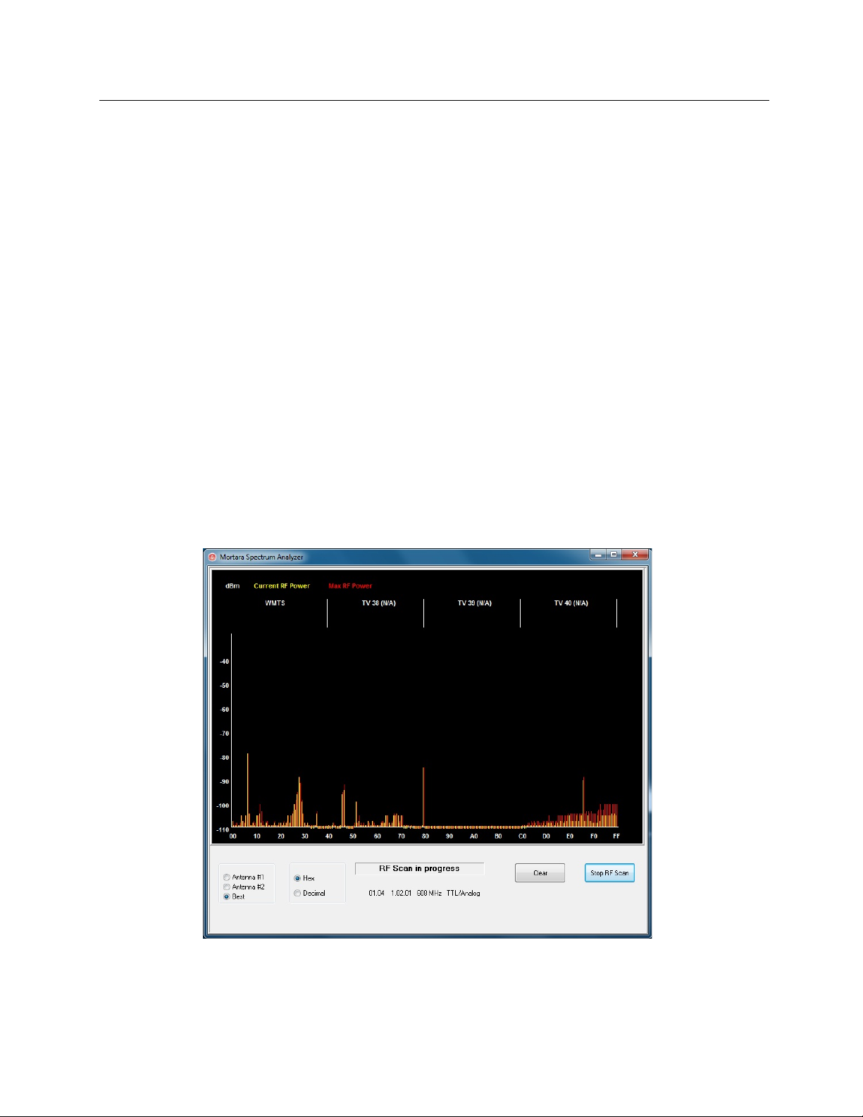
followed by Spectrum Analyzer to open the Mortara Spectrum Analyzer dialog window. To simplify
access, it is recommended to place a shortcut to this tool on the desktop.
The analyzer will scan all channels and display a bar graph showing the RF activity found on each
channel. Radio button selections allow choices for each antenna or Best (using both antennas) to search
for the channel having the lowest RF activity (smallest graphical bar) and set that channel on both the
X12+ transmitter and the XScribe. Channels in the graph can be displayed in Hex or Decimal values using
radio button selections as well.
To stop the RF scan, click the Stop RF Scan button. To clear the display, click the Clear button.
It is recommended to allow the RF Scan to run for a period of time during the times that the possibility for
interference is highest. The current RF power is colored amber and the maximum power for each channel
is colored red.
The example below shows that the best channel selections would be 16, 32, or 38 for a 608 MHz X12+
transmitter in the WMTS band.
NOTE: To change channels on the X12+ transmitter, refer to the device user manual. There are 256
channels available for the 2500 MHz transmitter and 64 channels available for the 608 MHz transmitter in
the WMTS band.
29
Page 45
UNIT DISASSEMBLY
SECTION 4
(For Mortara Supplied Hardware Only)
Before you begin
1. Put on your electrostatic discharge (ESD) wrist strap to avoid damaging any
circuitry.
2. Remove all devices (such as diskettes and CD-ROMs) from the computer.
3. Power off the computer and any peripheral devices that are connected to it.
4. Disconnect the power cord from the electrical outlet and then from the
computer. When the computer is plugged into an AC power source, there is
always voltage applied to the system board. You must disconnect the power
cord from the power source before opening the computer to prevent system
board or component damage.
5. Disconnect all peripheral device cables from the computer.
Static electricity
Static electricity can damage electrical components. Before removing or replacing a
component, touch a grounded metal object to discharge static electricity. Also observe
the following precautions to prevent damage to electric components and accessories:
To avoid hand contact, transport products in static-safe containers such as
tubes, bags, or boxes.
Protect all electrostatic parts and assemblies with conductive or approved
containers or packaging.
Keep electrostatic-sensitive parts in their containers until they arrive at static-free
stations.
Place items on a grounded surface before removing them from their container.
30
Page 46
UNIT DISASSEMBLY
SECTION 4
Always be properly grounded when touching a sensitive component or assembly.
Avoid contact with pins, leads, or circuitry.
Place reusable electrostatic-sensitive parts from assemblies in protective
packaging or conductive foam.
Disassembly
Warning: Be sure the AC power cord is disconnected prior to performing
servicing.
During disassembly, label each cable as you remove it, noting its position and
routing. This will make the replacement of the cables much easier, and will
ensure that the cables are rerouted properly to protect the cables.
Keep all screws with the units removed. The screws used in the computer are of
different thread sizes and lengths; using the wrong screw in a component could
damage the unit.
Access panel removal
1. Review the safety considerations before performing the steps listed below by
clicking on the following
CAUTION:
2. Pull up and hold the access panel release latch.
3. Rotate the panel up and lift it away from the chassis.
Failure to comply with the precautions could result in damage to your
product or loss of data.
31
Page 47
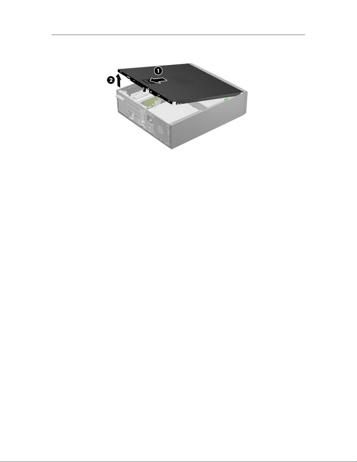
UNIT DISASSEMBLY
install the computer cover, reverse the removal procedure.
To
SECTION 4
32
Page 48
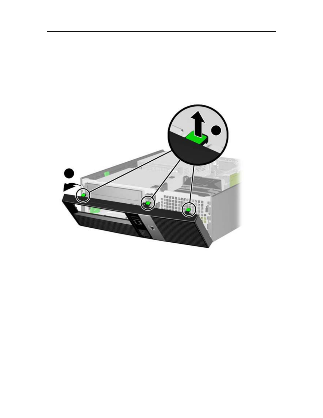
UNIT DISASSEMBLY
Front Bezel Removal
1. Prepare the computer for disassembly
2. Remove the access panel
3. Lift up the three tabs on the side of the bezel (1), then rotate the bezel off the
chassis (2).
SECTION 4
To install the new front bezel, reverse the removal procedure.
33
Page 49
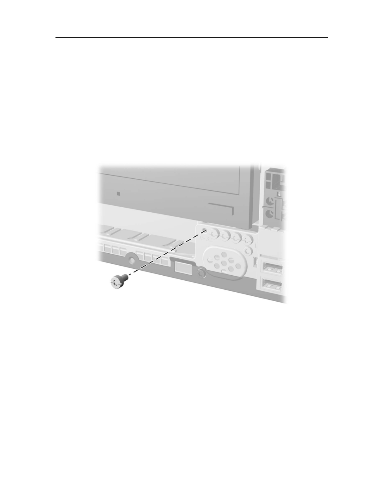
UNIT DISASSEMBLY
SECTION 4
Front Bezel Security
The front bezel can be locked in place by installing a security screw provided by HP.
To install the security screw:
1. Prepare the computer for disassembly
2. Remove the access panel
3. Remove the front bezel
4. Remove one of the five silver 6-32 standard screws located on the front of the
chassis behind the bezel.
5. Replace the front bezel.
6. Install the security screw next to the middle front bezel release tab to secure the
front bezel in place.
To remove the front bezel security screw, reverse the installation procedures.
34
Page 50

UNIT DISASSEMBLY
Power Supply Replacement
Warning: Be sure the AC power cord is disconnected prior to performing
servicing.
1. Prepare the computer for disassembly
2. Remove the access panel
3. Disconnect the cabling from the power supply to the motherboard and other
computer sub components
4. Remove the screws that fasten the power supply to the computer chassis
SECTION 4
35
Page 51

UNIT DISASSEMBLY
SECTION 4
XScribe Item Description Listing
Item # Part # Description
1 1404-002 TRANSFORMER ISOLATION 1000VA MED DOM (110VAC)
2 1404-003 TRANSFORMER ISOLATION 1000VA MED INTN'L (220VAC)
3 25004-003-52 CABLE TRACKMASTER TO CPU X-SCRIBE
4 25004-012-50 CABLE ERGOMETER INTERFACE ERGOLINE
5 30012-021-51 USB TRANSCEIVER KEY (UTK) MODULE RSCRIBE
6 30012-022-51 M12C-USB w/AUX OUTS INTERFACE ASSEMBLY
7 30012-022-61 M12RF611-USB w/AUX OUTS INTERFACE ASSY
8 30012-022-71 M12RF2500-USB w/AUX OUTS INTERFACE ASSY
9 3181-002 POWER CORD INTN'L CEE7/7+IEC320-C13
10 3181-003 POWER CORD BRIDGE 2m IEC320-C13+C14
11 3181-008 POWER CORD US/CAN HOSPITAL 5-15P+320-C13
12 34000-025-1002 Z200+ THERMAL WRITER A/A4
13 3510-005 PLUG TO PLUG ADAPTOR BNC
14 3600-003 ANTENNA TNC 2400MHz 1/2 WAVE LENGTH
15 3600-010 ANTENNA 611MHz BNC 1/4 WAVE
16 3601-001 COUPLER TNC FEMALE TO BNC FEMALE
17 6400-008 CABLE ETHERNET RJ-45M TO RJ-45M STR-THRU
18 6400-010 CABLE ETHERNET CAT5e RJ-45 M SHLD 2FT
19 6400-011 CABLE CROSSOVER CAT5e RJ-45 M SHLD 3FT
20 6400-012 CABLE USB TYPE A-TO-B FULL SPD
21 8342-007-01 SPACER A4 PAPER ELI 200+
22 8346-003-50 X12+ BATTERY DOOR
23 9900-014 MONITOR 24" LCD 1920x1200 WIDE DVI + VGA
24 9906-037 CPU LONG LIFE w/WINDOWS 7
25 9911-012-50 CART X-SCRIBE SYSTEM MPE
26 9911-012-51 STORAGE BIN MPE CART X-SCRIBE
27 9911-012-54 SWIVEL MOUNT BRACKET TANGO MODULE
28 9912-019 CABLE ERGOMETER INTERFACE LODE CORRIVAL
29 9960-051 NETWK CRD PCI 10/100/1000 GIGABIT ETHRNT
30 9960-052 ISOLATOR ETHERNET LOW LEAKAGE RJ45/RJ45
31 SERV PART 151-01 CABLE X-SCRIBE TO SUNTECH TANGO
32 SERV PART 184-01 LONG LIFE PC POWER SUPPLY
33 SERV PART 184-02 PS2 Keyboard & Mouse
34 X12PLUS-XXX-XXXX X12+ Transmitter
36
Page 52
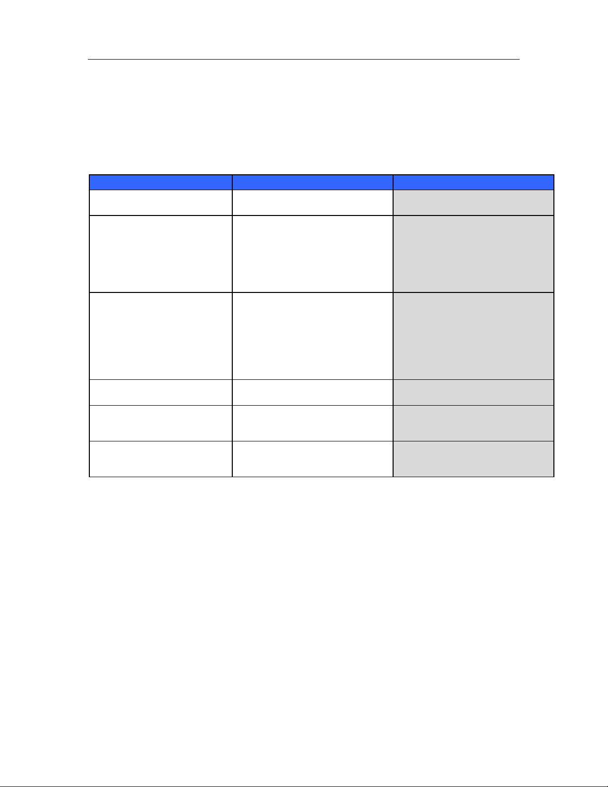
TROUBLESHOOTING
SECTION 5
The following is a list of common problems and resolutions that may be experienced. If the
problems that you are experiencing are not listed in this table please contact Mortara Instrument
Technical Support.
Troubleshooting Chart
Screen Message or Issue Possible Cause Solution
Baseline drift Poor skin-to-electrode contact. Re-prep skin and replace faulty
BP Printout and Report
discrepancy
Squared line(s) display on the
multi-lead rhythm display screen
or on the screen during the
exercise test
Muscle noise Electrode placed over muscle or fatty
No response to keyboard
commands
Menu cursor will not move Disconnected mouse cable.
electrode(s).
Use of BP field to enter new blood
pressure values.
Lead fail caused by poor skin-toelectrode contact.
Broken lead wire/cable.
Channel of transmitter doesn’t match
channel on XScribe.
tissue.
Disconnected keyboard cable.
Transposed keyboard/mouse cable.
Transposed keyboard/mouse cable.
BP value entry MUST BE completed
through the F3 key. Editing of BP is
completed through the selection of
the BP value on the right side of
display. Edited value will erase
previously entered value from
summary report.
Correct faulty lead(s) identified in
upper right corner of the screen.
Replace patient cable.
Match transmitter channel to same
channel setting in the Local Conf/F6
pop up window.
Find stable electrode site, re-prep
skin, and apply a new electrode.
Turn system OFF. Check keyboard
to mouse port connections.
Turn system OFF. Check mouse
port connections.
37
Page 53

TROUBLESHOOTING
SECTION 5
Troubleshooting Chart (Continued)
Screen Message or Issue Possible Cause Solution
Treadmill does not respond to
the ON command from X-Scribe
Z200+ writer paper out, light on
Z200+ writer not printing
Uneven printing of ECGs or
reports
Treadmill belt starts to slip When loose it can shift. Tighten adjustment bolts on both
ECG Front-End Error – Can’t
Proceed
Equipment powered up in wrong
sequence.
Treadmill power switch is off, or
treadmill cable not properly attached.
Emergency stop switch is engaged.
Treadmill settings are incorrect.
Paper jammed.
No paper in tray.
Open writer door.
Printer head needs cleaning.
The Front-End device is not correctly
connected.
The Front-End device drivers are not
correctly installed.
Incorrect Power Savings settings.
Turn treadmill OFF using Softkey
menu. Turn power to the treadmill
OFF. Wait one minute and turn
power back ON. Proceed with test.
Secure the treadmill to X-Scribe
cable connections. Turn treadmill
main power switch ON. (Switch is
located at the base of the treadmill
hood, left side.)
Reset emergency stop switch by
turning clockwise one-quarter turn.
Reset X-Scribe.
Set treadmill to proper setting for
corresponding treadmill.
Open writer cover and remove
jammed paper.
Insert new packet of paper in tray.
See if writer door is latched.
Refer to printer head cleaning
instructions in Appendix F.
sides until slippage stops.
Disconnect the USB cable from the
PC. Reconnect the USB cable to the
PC. The system emits a confirmation
beep.
Contact Mortara Service.
Restart the PC. Should rebooting the
system fix the problem, it is likely that
system has incorrect Power Saving
settings. Try the following:
1) Close the XScribe application.
2) Select “Start”, “Settings”, then
“Control Panel”.
3) Double click on “Power
Management” icon.
4) If displaye d, set “Stand-by”
setting to “Never”.
5) Click OK and c lose all open
Windows.
6) Reboot system.
38
Page 54

TROUBLESHOOTING
Troubleshooting Chart (Continued)
Screen Message or Issue Possible Cause Solution
SECTION 5
No Exams are Currently
Selected
A warning sign appears on the
screen next to ST
measurements.
RA/LA//LL/V1/V2/V3/V4/V5/V6
or C1/C2/C3/C4/C5/C6 FAIL
X12+ signal shows artifact even
when tested with a simulator.
No signal onscreen
An attempt to access a final report
but no patient is selected from the
Search Exam list.
The measurement points (J-point,
Isoelectric point, or J+ XX msec)
have been modified by the user
during or after the stress test.
One or more leads are in fail.
Signal onscreen shows artifact even
when tested with a simulator.
With the patient connected (or with a
simulator) no waveforms are
displayed, but only the squared
waveform/lead fail indicator appears
(wireless option).
NOTE: if neither the signal nor the
squared waveform is present, ESC or
Abort and start a new exam from the
main menu.
Click on the patient name to select
and access the file.
Warning sign indicates that a manual
change occurred and that the results
are now based on new user
determinations.
Connect or replace the electrodes to
turn off the warning message.
Check that no medical equipment is
operating at the same frequency in
proximity of the system. Run the RF
Scan tool (spectrum analyzer) to
locate the optimal channel setting for
transmission. Make sure to set the
same channel on the X12+ and
XScribe.
Check that XScribe and the digital
transmitter work on the same
channel. Refer to the transmitter
user manual to check and change
channel. Refer to Settings in this
manual to set the receiving channel
for XScribe.
39
Page 55

TROUBLESHOOTING
Troubleshooting Chart (Continued)
Screen Message or Issue Possible Cause Solution
SECTION 5
No signal from X12+ Transmitter
No signal from the M12A patient
cable connection
No signal from the AM12 patient
cable connection
No Network or LAN
communication
X12+ is not selected as Front End.
M12RF-USB cable is unplugged.
Drivers for M12RF-USB not loaded.
M12A is not selected as Front End.
USB cable plugged into wrong USB
slot.
Drivers for M12-USB patient module
not loaded.
AM12 not selected as Front End.
Drivers for AM12 patient cable not
loaded.
RJ45 plug connected to the wrong
RJ45 slot.
Select X12+ as front end in the
Observation screen.
Place USB plug into any rear USB
slot.
Load drivers for M12-USB from
XScribe software CD.
Select M12 as front end in the
Observation screen.
Assure M12-USB Green light is on, if
not plug USB cable into the USB
adapter on the upper left-hand side.
Load drivers for M12-USB from
XScribe software CD.
Select AM12 as front end in the
Observation screen.
Load drivers for AM12 from XScribe
software CD.
Disconnect the RJ45 plug from the
back of the PC and connect it to the
other RJ45 slot.
40
Page 56

CONFORMANCE TESTING
SECTION 6
Conformance Testing
Conformance testing is to be performed by Authorized Mortara Service Representatives to verify
the device is functioning correctly after repair operations have been performed. Testing results
should be documented on the test data record at the end of this section of the manual.
Acquisition module preparation
Connect a patient simulator to an X12+ or AM12 patient interface. If using an AM12 interface,
connect the AM12 to a USB port on the PC.
System Checks
Archive Management
With customer’s assistance, create additional Archive folders on the root directory or on
the network (if option installed). Refer to the XScribe User Manual (9515-151-50-ENG)
for complete instructions. Archive all the patient exams from the root Archive to the newly
created Archive locations.
Hard Drive Space
Check the capacity of the system hard drive to ensure there is sufficient space for system
operation. If the system drive is nearing capacity (approaching 90%), this issue should be
discussed with the facility to create additional space for proper operation. If the drive was
near capacity and unnecessary files were removed, a defragmentation may be performed
to ensure optimal performance of the drive.
Note: The defragmentation process may take several hours and is only required in
extreme cases.
Z200+ Writer Test
Using the Z200Plus Monitor software, print off a test page. The Z200PlusMonitor
software can be loaded onto the X-Scribe system or ran from USB stick. Double click
Z200PlusMonitor icon to launch the application. Press Connect and then press Print Test
Page. Verify on the print out page that there are no missing pixels or light printing. Now
press Disconnect and close the application.
41
Page 57

CONFORMANCE TESTING
Functional Testing
• Click on the Start Stress Test icon and select the Search Patient button. Click New
Patient and enter test patient demographics.
• Click Confirm and verify the test starts. ECG data should begin to be displayed. Verify
Bruce is the selected protocol from the top left hand drop down menu.
• Click the Begin button and allow about a minute of data to be collected. Then press the
Start Exe button and verify treadmill turns on and begins to move.
• Allow the system to run through the full Bruce protocol. Verify treadmill is rising and that
the speed increases throughout test. Verify printouts are coming from Z200+ writer or
Laser Printer (if the option is installed).
• Once the test enters the Recovery phase, verify the treadmill slows down and returns to
0% grade. Press the ECG F11 button and verify a printout comes from the Z200+ writer
or Laser Printer (if the option is installed).
• Press the END F1 button and verify the test goes in to the Report Manager screen.
Real Time ECG data should still be displayed at the bottom of screen. Press the ECG
button and verify a printout comes from the Z200+ writer or Laser Printer (if the option
is installed).
• Press the EXIT button and verify system exits the Report Manager screen.
• Verify the test results were stored properly in the appropriate location, and that any
configured data export options were performed.
Safety Testing
The following safety tests should be performed in accordance with IEC 60601 or IEC 62353
standards and all local regulatory requirements:
• Earth Leakage (performed on medical isolation transformer)
• Enclosure Leakage (performed on medical isolation transformer)
The following safety tests are required only for systems utilizing a wired patient interface.
• Patient Leakage
• Patient Leakage Type-F
• Patient Auxiliary Current
SECTION 6
42
Page 58

CONFORMANCE TESTING
XScribe 5 System - Test Data Record
XScribe Serial #: _________________________________________
Treadmill Serial #: _________________________________________
□ System Checks
□ Archive management
□ Sufficient Hard drive space
□ Print writer test page and inspect for proper operation/darkness
□ Functional Testing
□ Perform lead check on system transmitter(s) and patient cable(s)
□ Perform a full stress test with a patient simulator
□ Verify treadmill turns on as per protocol settings
□ Verify writer prints as per protocol settings
□ Verify test results were properly stored
□ Verify data export functionality (if option installed)
□ Safety Testing
□ Earth Leakage
□ Transformer Enclosure Leakage
(The following tests are performed for wired patient inputs only)
□ Patient Leakage
□ Patient Leakage Type-F
□ Patient Auxiliary Current
_____________________________________________________________________________
□ Treadmill Inspection / Maintenance
□ Running Belt Cleaning & Inspection
□ Running Belt Tension Check / Adjustment
□ Drive Belt Tension Check / Adjustment
□ Elevation Screw Lubrication
□ Control Cable Fastened/Routed Appropriately
□ Treadmill Functional Testing
□ Test Plug Operation
□ XScribe Control Test
□ Emergency Stop Button Check
Performed By:________________________________________ Date: ______/______/______
SECTION 6
43
Page 59

COMMUNICATION OPTIONS
SECTION 7
File Exchange
XScribe supports the ability to import orders from XML files and export PDF and XML
results to an external system depending on the activated system features. Import/Export
directories for the selected group are defined in the File Exchange window in System
Configuration.
XScribe also supports DICOM communications. DICOM settings are entered through the
System Configuration icon, then clicking on the DICOM Settings button.
Refer to the Scribe Data Exchange Administrator Manual (P/N: 9515-185-51-ENG) for
external system integration details.
44
Page 60
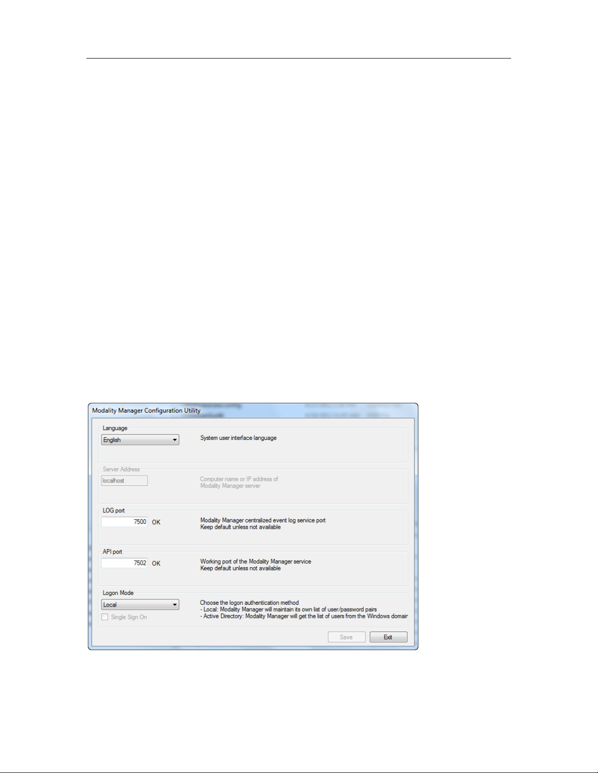
System Utilities
System Utilities
The following utilities are located at the path below to assist with system
configuration and service functions as defined.
C:\Program Files (x86)\Mortara Instrument Inc\ModalityMgr
Configurator.exe (language, networking, login)
FetchAllConfig.exe (gathers all system configuration data)
ActivationTool.exe (software license information)
CFDWizard.exe (display and report configurator)
Configurator.exe
The Modality Manager Configuration Utility is stored as a unique EXE file
(Configurator.exe) that can be accessed after the installation process is
completed if
any changes are needed to the Modality Configuration settings.
SECTION 8
45
Page 61

System Utilities
SECTION 8
Refer to the following information regarding the configuration settings:
Language: This setting is always available to select the desired language.
Server Address: The Server Address will read “localhost” if the local PC is
hosting the Modality Manager database. If Modality Manager is not local, this box
should contain the IP Address or Computer Name of the PC or server hosting
Modality Manager.
Log Port: This setting is always available to select the port to be used for the
event log service.
API Port: This setting is always available to select the port to be used for
Modality Manager service.
Logon Mode: This setting can be set to either Local or Active Directory
depending on the user preference. If Local is selected, the Modality Manager
service will maintain its own local listing of user/password pairs for logging onto
the system.
If Active Directory is selected, the Modality Manager service will access the list of
users from the Windows domain.
46
Page 62
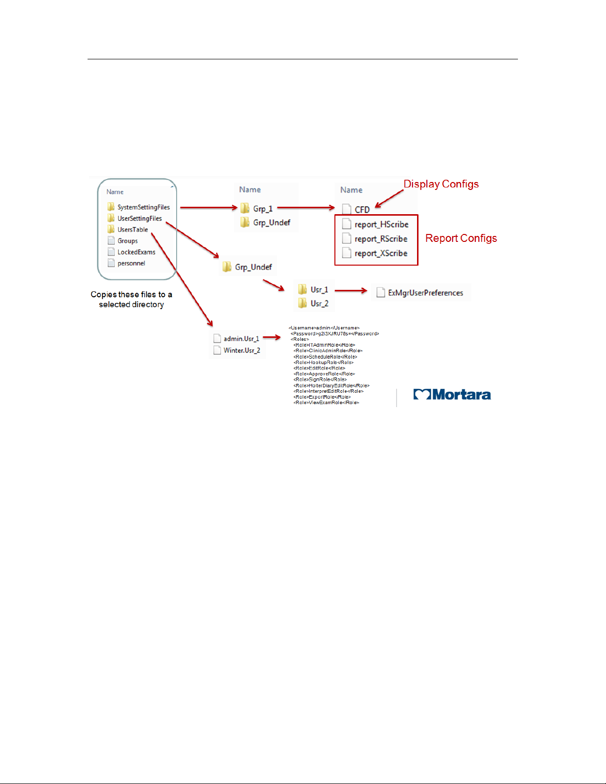
System Utilities
SECTION 8
FetchAllConfig.exe
Copies all of the system configuration settings into the file structure displayed
below to allow this information to be sent to a Mortara Service Center. The path
can be entered by the user upon executing the utility.
47
Page 63
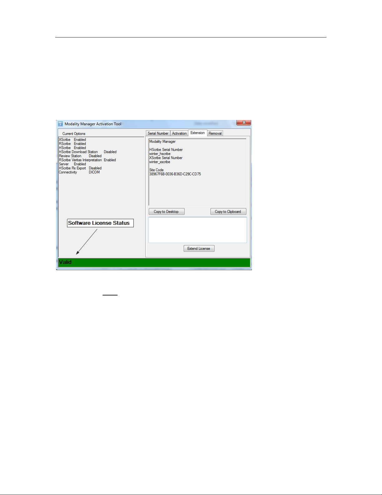
System Utilities
SECTION 8
ActivationTool.exe
This utility will display the current software license status, serial number
information, and all enabled options.
The serial number information is necessary when contacting a Mortara Service
Center for technical assistance.
The Activation Utility is also used to perform a software Removal, which MUST
be performed prior to uninstalling the Mortara software. The software Removal
process will generate a Removal Code, which will need to be sent to Mortara to
provide notification that the software license has been deactivated.
Once the software Removal has been reported to Mortara, the software may be
loaded on another computer and activated through the normal activation process.
48
Page 64
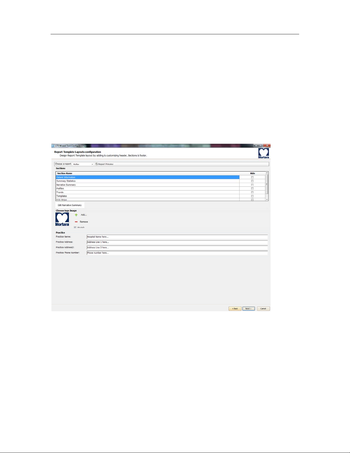
System Utilities
CFDWizard.exe
The CFD (Custom Format and Display) Wizard can be used to change the
following items:
• Logo
• Facility Name
• Facility Address
• Phone Number
• Hide Items
SECTION 8
Customization of the Scribe 5 display appearance and reports are also available.
Please contact your regional Mortara Service Center for assistance with this level
of customization.
49
Page 65

System Backup and Restoration
SECTION 9
System Backup
The Scribe 5 system installs a batch file that will back up all of the necessary data required to
restore the system to operation in the case of a system failure. This file can be modified to direct
the system to store the backup data to an alternate non-local location or designated storage
system (recommended).
User must
The backup file is located at the following path:
C:\Program Files\Mortara Instrument Inc\Mortara PgSql\scripts>Backup.bat
Executing the system backup copies the following information into a file called
CorScribeFullBackup.7z located on the TEMP folder of the logged in user.
be logged into the operating system as a user with administrative permissions.
• Double click on Backup.ba t
• A Command Prompt window will open and the backup process will begin, once the
Command Prompt window closes the backup is complete.
• SQL Database information
• Full Disclosure Data
• User Configuration Settings
This may be a hidden file based on the current system settings.
Backup Notes:
Caution
Configuration settings made via the Modality Manager Configuration tool and the SW Activation
utility are not stored in the DB, and are not
The following items will need to be properly configured with the use of the tools/utilities after the
restoration process:
• Language setting (in the server)
• The ports where the MM server and Lo g server can be found
• The authentication method (local vs. AD vs. AD+SSO)
• Serial number
• License/features
In case of restoring from a total failure (unrecoverable system, reinstall of the OS etc…), the
first group of settings should be correctly reentered during the install of the application. The
user will have to go through the activation process again, hence an Activation Code will have to
be regenerated (the old Activation Code cannot be used) and – during the p rocess – S/N
should be restored.
Everything else (users, DICOM settings, Modality settings etc…) is in the DB, hence it is
backed up.
included in the system backup.
50
Page 66

System Backup and Restoration
• It is recommended that the backup be performed while the system applications are not in
use (not receiving any data).
• The Backup.bat routine can be added as a scheduled process through the Task
Scheduler
• If a local backup (factory default) is used It is recommended that after a backup has been
performed that the file created from the backup be removed from the system and placed
in a safe (non-local) location.
• The process is the same for a stand-alone system and a distributed system; when
performing the backup on a distributed system the process must be perfo rmed on the PC
or server that is running Modality Manager.
• The backup process can be customized by modifying the DefaultBackupSettings.bat file
and renaming the modified file to CustomBackupSettings.bat
o Information regarding modifications to the backup file is located within the
Backup.bat file itself.
o Please contact Mortara Instrument Technical Support Group if you require
assistance with modifying the backup file.
o Mortara technical support can assist with the modification of the backup file,
however Mortara will not retain a copy of the file.
• On a distributed system the backup zip file may be parked in a sub folder:
C:\Users\<User>\AppData\Local\Temp\1
This may be a hidden file based on the current system settings.
SECTION 9
51
Page 67

System Backup and Restoration
System Restoration (restores to point of last performed backup)
Caution
• It is recommended that the resto re be performed while the system applications are not in
use (not receiving any data).
• The process is the same for a stand-alone system and a distributed system; when
performing a Restore operation on a distributed system the process must be performed
on the PC or server that is running Modality Manager.
The following process should be followed to restore a Scribe 5 system.
1. Prepare/Repair PC
2. Load OS (if applicable)
3. Install Product Software
4. Place file CorScribeFullBackup.7z in the correct restore location
5. Run Restore batch file
User must
be logged into the operating system as a user with administrative permissions.
• Place the backup file into the appropriate folder:
C:\Users\<Administrator Name>\AppData\Local\Temp
On a distributed system the file may be located is a sub folder:
C:\Users\<user>\AppData\Local\Temp\1
This may be a hidden file based on the current system settings.
• Navigate to the following path to locate the Restore.bat file
C:\Program Files\Mortara Instrument Inc\Mortara PgSql\scripts>Restore.bat
• Double click on the Restore.bat file
• A Command Prompt window will open and the Restore process will begin
• The Restore program will ask whether or not CreateDB.BAT will need to be run before
the restore is executed. If the system database does not need to be recreated, answer
NO to this question. If the system database has been damaged, or is being recreated,
answer YES to this question.
SECTION 9
52
Page 68

System Backup and Restoration
• Once the Command Prompt window closes the backup utility has completed restoring the
following content:
o SQL Database information
o Full Disclosure Data
o User Configu ration Setting s
• Verify that the appropriate data has been restored (system settings or system se ttings
and exam data) and that the exams can be accessed.
SECTION 9
53
 Loading...