

Page 1
REF 9515-164-50-ENG Rev D1
X12+
AMBULATORY TRANSMITTER
USER MANUAL
Manufactured by Mortara Instrument, Inc., Milwaukee, Wisconsin U.S.A.
CAUTION: Federal law restricts this device to sale by or on the order of a physician.
Page 2

Copyright © 2015
by Mortara Instrument, Inc.
7865 N. 86th Street
Milwaukee, Wisconsin 53224
This document contains confidential information that belongs to Mortara Instrument, Inc. No part of this document
may be transmitted, reproduced, used, or disclosed outside of the receiving organization without the express written
consent of Mortara Instrument, Inc. Mortara is a registered trademark of Mortara Instrument, Inc. X12+ is a
trademark of Mortara Instrument, Inc.
Page 3

TECHNICAL SUPPORT AND SERVICE
Headquarters
Mortara Instrument, Inc.
7865 North 86th Street
Milwaukee, WI 53224
U.S.A.
Tel: 414.354.1600
Tel: 800.231.7437
Fax: 414.354.4760
Internet: http://www.mortara.com
European Union
Representative
Mortara Instrument Europe, s.r.l.
(European Headquarters)
Via Cimarosa 103/105
40033 Casalecchio di Reno (BO)
Italy
Tel: +39.051.298.7811
Fax: +39.051.613.3582
Service/Technical
Support Group
Mortara Instrument, Inc.
7865 North 86th Street
Milwaukee, WI 53224
U.S.A.
Tel: 414.354.1600
Service: 888.MORTARA
(888.667.8272)
Fax: 414.354.4760
E-mail: [email protected]
Sales Support/
Supplies & Accessories
Mortara Instrument, Inc.
7865 North 86th Street
Milwaukee, WI 53224
U.S.A.
Tel: 414.354.1600
Fax: 414.354.4760
Hospital Customers: [email protected]
Physician Practice: [email protected]
U.S. Distribution: [email protected]
Mortara Instrument Germany
Bonifaciusring 15
45309 Essen
Germany
Tel: +49.201.18 55 69 70
Fax: +49.201.18 55 69 77
Mortara Instrument Netherlands
Postbus 324
5680 AH Best
Industrieweg 160b
5683 CG Best
Netherlands
Tel: +31.499.377310
Fax: +31.499.377908
Mortara Instrument Australia
PO Box 7568
Baulkham Hills NSW 2153
Unit 28, 9 Hoyle Avenue
Castle Hill NSW 2154
Australia
Tel: +61 2 8070 9303
Fax: +61 2 9899 9478
Mortara Dolby UK Ltd.
Units 11 & 12, Scion House
Stirling University Innovation Park
Stirling FK9 4NF
Scotland
Tel: +44.1786.444980
Fax: +44.1786.446630
i
Page 4

NOTICES
Manufacturer’s Responsibility
Mortara Instrument, Inc. is responsible for the effects on safety and performance only if:
• Assembly operations, extensions, readjustments, modifications, or repairs are carried out only by persons
authorized by Mortara Instrument, Inc.
• The device is used in accordance with the instructions for use.
Responsibility of the Customer
The user of this device is responsible for ensuring the implementation of a satisfactory maintenance schedule.
Failure to do so may cause undue failure and possible health hazards.
Equipment Identification
Mortara Instrument, Inc. equipment is identified by a serial and reference number on the back of the device. Care
should be taken so that these numbers are not defaced.
Copyright and Trademark Notices
This document contains information that is protected by copyright. All rights are reserved. No part of this
document may be photocopied, reproduced, or translated to another language without prior written consent of
Mortara Instrument, Inc.
Other Important Information
The information in this document is subject to change without notice.
Mortara Instrument, Inc. makes no warranty of any kind with regard to this material including, but not limited to,
implied warranties of merchantability and fitness for a particular purpose. Mortara Instrument, Inc. assumes no
responsibility for any errors or omissions that may appear in this document. Mortara Instrument, Inc. makes no
commitment to update or to keep current the information contained in this document.
ii
Page 5

WARRANTY INFORMATION
Your Mortara Warranty
MORTARA INSTRUMENT, INC. (hereafter referred to as “Mortara”) warrants that components within Mortara
products (hereafter referred to as “Product/s”) will be free from defects in workmanship and materials for the
number of years specified on documentation accompanying the product, or previously agreed to by the purchaser
and Mortara, or if not otherwise noted, for a period of twelve (12) months from the date of shipment.
Consumable, disposable or single use products such as, but not limited to, PAPER or ELECTRODES are warranted
to be free from defects in workmanship and materials for a period of 90 days from the date of shipment or the date
of first use, whichever is sooner.
Reusable product such as, but not limited to, BATTERIES, BLOOD PRESSURE CUFFS, BLOOD PRESSURE
HOSES, TRANSDUCER CABLES, Y-CABLES, PATIENT CABLES, LEAD WIRES, MAGNETIC STORAGE
MEDIUMS, CARRY CASES or MOUNTS, are warranted to be free from defects in workmanship and materials for
a period of 90 days. This warranty does not apply to damage to the Product/s caused by any or all of the following
circumstances or conditions:
a) Freight damage;
b) Parts and/or accessories of the Product/s not obtained from or approved by Mortara;
c) Misapplication, misuse, abuse, and/or failure to follow the Product/s instruction sheets and/or information
guides;
d) Accident; a disaster affecting the Product/s;
e) Alterations and/or modifications to the Product/s not authorized by Mortara;
f) Other events outside of Mortara’s reasonable control or not arising under normal operating conditions.
THE REMEDY UNDER THIS WARRANTY IS LIMITED TO THE REPAIR OR REPLACEMENT WITHOUT
CHARGE FOR LABOR OR MATERIALS, OR ANY PRODUCT/S FOUND UPON EXAMINATION BY
MORTARA TO HAVE BEEN DEFECTIVE. This remedy shall be conditioned upon receipt of notice by Mortara
of any alleged defects promptly after discovery thereof within the warranty period. Mortara’s obligations under the
foregoing warranty will further be conditioned upon the assumption by the purchaser of the Product/s (i) of all
carrier charges with respect to any Product/s returned to Mortara’s principal place or any other place as specifically
designated by Mortara or an authorized distributor or representative of Mortara, and (ii) all risk of loss in transit. It
is expressly agreed that the liability of Mortara is limited and that Mortara does not function as an insurer. A
purchaser of a Product/s, by its acceptance and purchase thereof, acknowledges and agrees that Mortara is not liable
for loss, harm, or damage due directly or indirectly to an occurrence or consequence therefrom relating to the
Product/s. If Mortara should be found liable to anyone under any theory (except the expressed warranty set forth
herein) for loss, harm, or damage, the liability of Mo rtara shall be limited to the lesser of the actual loss, harm, or
damage, or the original purchase price of the Product/s when sold.
iii
Page 6

WARRANTY INFORMATION
EXCEPT AS SET FORTH HEREIN WITH RESPECT TO REIMBURSEMENT OF LABOR CHARGES, A
PURCHASER’S SOLE EXCLUSIVE REMEDY AGAINST MORTARA FOR CLAIMS RELATING TO THE
PRODUCT/S FOR ANY AND ALL LOSSES AND DAMAGES RESULTING FROM ANY CAUSE SHALL BE
THE REPAIR OR REPLACEMENT OF DEFECTIVE PRODUCT/S TO THE EXTENT THAT THE DEFECT IS
NOTICED AND MORTARA IS NOTIFIED WITHIN THE WARRANTY PERIOD. IN NO EVENT,
INCLUDING THE CLAIM FOR NEGLIGENCE, SHALL MORTARA BE LIABLE FOR INCIDENTAL,
SPECIAL, OR CONSEQUENTIAL DAMAGES, OR FOR ANY OTHER LOSS, DAMAGE, OR EXPENSE OF
ANY KIND, INCLUDING LOSS OF PROFITS, WHETHER UNDER TORT, NEGLIGENCE OR STRICT
LIABILITY THEORIES OF LAW, OR OTHERWISE. THIS WARRANTY IS EXPRESSLY IN LIEU OF ANY
OTHER WARRANTIES, EXPRESS OR IMPLIED, INCLUDING, BUT NOT LIMITED TO THE IMPLIED
WARRANTY OF MERCHANTABILITY AND THE WARRANTY OF FITNESS FOR A PARTICULAR
PURPOSE.
iv
Page 7

USER SAFETY INFORMATION
Warning:
Caution:
Note:
Warning(s)
This manual gives important information about the use and safety of this device. Deviating from operating
procedures, misuse or misapplication of the device, or ignoring specifications and recommendations could
result in increased risk of harm to users, patients and bystanders, or damage to the device.
Device transmits data reflecting a patient’s physiological condition to a properly equipped receiving device that
when reviewed by a trained physician or clinician, can be useful in determining a diagnosis; however, the data
should not be used as a sole means for determining a patient’s diagnosis.
Users are expected to be licensed clinical professionals knowledgeable about medical procedures and patient
care, and adequately trained in the use of this device. Before attempting to use th is device for clinical
application, the operator must read and understand the contents of the user manual and other accompanying
documents. Inadequate knowledge or training could result in increased risk of harm to users, patients and
bystanders, or damage to the device. Contact Mortara service for additional training options.
To maintain designed operator and patient safety, peripheral equipment and accessories used that can come in
direct patient contact must be in compliance with UL 60601-1, IEC 60601-1 and IEC 60601-2-25. Only use
parts and accessories supplied with the device and available through Mortara Instrument, Inc.
Patient cables intended for use with the device include series resistance (9 Kohm minimum) in each lead for
defibrillation protection. Patient cables should be checked for cracks or breakage prior to use.
Conductive parts of the patient cable, electrodes, and associated connections of type CF applied parts, including
the neutral conductor of the patient cable and electrodes, should not come into contact with other conductive
parts including earth ground.
ECG electrodes could cause skin irritation; patients should be examined for signs of irritation or inflammation.
To avoid the possibility of serious injury or death during patient defibrillation, do no t co me into co ntact with
device or patient cables. Additionally, proper placement of defibrillator paddles in relation to the electrodes is
required to minimize harm to the patient.
Defibrillation protection is guaranteed only if the original patient cable is used. Any modification of this device
may alter defibrillator protection.
This device was designed to use the electrodes specified in this manual. Proper clinical procedure must be
employed to prep the electrode sites and to monitor the patient for excessive skin irritation, inflammation, or
other adverse reactions.
Means there is the possibility of personal injury to you or others.
Means there is the possibility of damage to the device.
Provides information to further assist in the use of the device.
v
Page 8

USER SAFETY INFORMATION
To avoid potential for spread of disease or infection, single-use disposable components (e.g., electrodes) must
not be reused. To maintain safety and effectiveness, electrodes must not be used beyond their expiration date.
FCC Warning (Part 15.21): Changes or modifications not expressly approved by the party responsible for
compliance could void the user’s authority to operate the device.
A possible explosion hazard exists. Do not use the device in the presence of a flammable anesthetic mixture.
The device has not been designed for use with high-frequency (HF) surgical equipment and does not provide a
protective means against hazards to the patient.
The quality of the signal produced by the device may be adversely affected by the use of other medical
equipment, including but not limited to defibrillators and ultrasound machines.
There is no known safety hazard if other equipment, such as pacemakers or other stimulators, is used
simultaneously with the device; however, disturbance to the signal may occur.
Operations may be affected in the presence of strong electromagnetic sources such as electrosurgery equipment.
The battery operated device transmits data reflecting a patient’s physiological condition to a receiving device.
During operation failure, data transmission and LCD information will cease to occur. In mission critical
conditions, it is advisable to have a backup device available.
There is a potential pinch hazard when applying the battery compartment cover to the device that could result in
minor injury. Care should be taken to avoid entrapment of fingers when performing this operation.
The device is restricted to use on one patient at a time.
The performance of the device may be compromised by excessive motion.
Use only recommended battery cells. Use of other cells may present a risk of fire or explosion.
vi
Page 9

USER SAFETY INFORMATION
Caution(s)
To prevent possible damage to the keypad, do not use sharp or hard objects to depress keys, only use fingertips.
Do not attempt to clean the device or patient cables by submersing into a liquid, autoclaving, or steam cleaning
as this may damage equipment or reduce its usable life. Use of unspecified cleaning/disinfecting agents, failure
to follow recommended procedures, or contact with unspecified materials could result in increased risk of harm
to users, patients and bystanders, or damage to the device. Do not sterilize the device or patient cables with
Ethylene Oxide (EtO) gas.
The device and patient cable should be cleaned between each use. Inspect cable and connections for damage or
excessive wear prior to each use. Replace cable if damage or excessive wear is noted.
Do not pull or stretch patient cables as this could result in mechanical and/or electrical failures. Patien t cab les
should be stored after forming them into a loose loop.
The device will only work with receiving devices that are equipped with the appropriate option.
No user-serviceable parts are inside. Damaged or suspected inoperative equipment must be immediately
removed from use and must be checked/repaired by qualified service personnel prior to continued use.
This device is not recommended for use in the presence of imaging equipment such as Magnetic Resonance
Imaging (MRI) and Computed Tomography (CT) devices, etc.
The following equipment may cause interference with the RF channel: microwave ovens, diathermy units with
LANs (spread spectrum), amateur radios, and government radar.
When necessary, dispose of the device, its components and accessories (e.g., batteries, cables, electrodes),
and/or packing materials in accordance with local regulations.
Wipe the exterior surface of the device and patient cables with a sterilizing disinfectant and then dry with a
clean cloth.
AA batteries are known to leak their contents when stored in unused equipment. Remove battery from device
when not used for an extended period of time.
To prevent possible damage to the device during transport and storage (while in original packaging) the
following environmental conditions must be adhered to:
Ambient Temperature Range: -20°C to 65°C (-4°F to 149°F)
Relative Humidity Range: 5% to 95% (non-condensing)
Atmosphere Pressure: 700 hPa to 1060 hPa
Allow the device to stabilize within its intended operating environment for a minimum of two hours prior to
use. The allowable operating environment is as follows:
Ambient Temperature Range: 0°C to 45°C (32°F to 113°F)
Relative Humidity Range: 5% to 95% (non-condensing)
Atmosphere Pressure: 700 hPa to 1060 hPa
vii
Page 10

USER SAFETY INFORMATION
FCC Compliance Statement
In the United States use of this device is regulated by the Federal Communications Commission (FCC). The device
with its antenna complies with FCC’s RF exposure limits for general population/uncontrolled exposure.
FCC Warning (Part 15.21): Changes or modifications not expressly approved by the party responsible for
compliance could void the user’s authority to operate the device.
X12+ (600) FCC ID: HJR-X12-600-15
X12+ (2500) FCC ID: HJR-X12P-2500
X12+ (915) FCC ID: HJR-X12P-915
These devices comply with Part 15 of the FCC rules. Operation is subject to the followin g conditions:
1. This device may not cause harmful interference, and
2. This device must accept any interference received, including interference that may cause undesired operation.
The X12+ (600) must be used solely on the premises of healthcare facilities (see Part 15, section 15.242a).
A healthcare facility operating the X12+ (600) must coordinate with the directors of existing nearby TV
stations and radio astronomy observatories to ensure compatible use. Minimum separation distances from such
facilities may apply. It may be necessary to obtain written authorization from such facilities prior to installation
and use of the X12+ (Part 15, section 15.242d,e).
Industry Canada Compliance Statement
These devices comply with RSS-210 of the Industry Canada rules. Operation is subject to the following two
conditions:
1. This device may not cause interference, and
2. This device must accept any interference, including interference that may cause undesired operation of the
device.
X12+ (915) IC: 3758-X12P915
The term "IC:" before the certification/registration number only signifies that the Industry Canada technical
specifications were met.
X12+ (600) Certification Number: 3758A - 104616
This telemetry device is only permitted for installation in hospitals and healthcare facilities. Devices shall not be
operated in mobile vehicles (even
installer/user of this
Columbia latitude: 49° 19' 12" N, longitude: 118° 59' 56" W). For medical telemetry systems
80 km separation (e.g., the Okinagan valley, British Columbia), the installer/user
the written concurrence of the Director of the Penticton radio
installed or operated. The Penticton contact is Tel: 250-493-2277/Fax: 250-493-7767.
device shall ensure that it is at least 80 km from the Penticton radio astronomy station (British
ambulances and other vehicles associated with healthcare facilities). The
not meeting this
must coordinate with and obtain
astronomy station before the equipment can be
viii
Page 11

USER SAFETY INFORMATION
Note(s)
Proper patient preparation is important to proper application of ECG electrodes and operation of the device.
If electrode is not properly connected to the patient, or one or more of the patient cable lead wires is damaged,
display will indicate a lead fault for the lead(s) where the condition is present.
For additional instructions and warnings, refer to the user manual of the receiving monitoring device.
As defined by IEC 60601-1 and IEC 60601-2-25, the device is classified as follows:
- Class I equipment or internally powered
- Type CF defibrillation-proof applied parts
- Ordinary equipment
- Equipment not suitable for use in the presence of a flammable anesthetic mixture
- Continuous operation
Th e device will automatically turn off (blank screen) if the batteries have been severely discharged.
The device is UL classified:
Medical Equipment
WITH RESPECT TO ELECTRIC SHOCK, FIRE, AND MECHANICAL HAZARDS
ONLY, IN ACCORDANCE WITH UL 60601-1, CAN/CSA C22.2 No. 601.1,
IEC60601-1 AND IEC60601-2-25.
ix
Page 12

USER SAFETY INFORMATION
x
Page 13

EQUIPMENT SYMBOLS AND MARKINGS
Symbol Delineation
Attention, consult accompanying documents
Defibrillator-proof, Type CF input
Battery
Indicates compliance to applicable European Union directives
Do not dispose as unsorted municipal waste. Per European Union
Directive 2002/96, requires separate handling for waste disposal according
to national requirements
xi
Page 14

GENERAL CARE
Precautions
Turn off the device before inspecting or cleaning.
Do not immerse the device in water.
Do not use organic solvents, ammonia-based solutions, or abrasive cleaning agents which may damage
equipment surfaces.
Inspection
Inspect your equipment daily prior to operation. If you notice anything that requires repair, contact an authorized
service person to make the repairs.
Verify that all cables and connectors are securely seated.
Check the case for any visible damage.
Inspect cables and connectors for any visible damage.
Inspect buttons and controls for proper function and appearance.
Cleaning and Disinfection
Refer to section 3 for proper cleaning and disinfection procedures.
Sterilization
EtO sterilization is not recommended but may be required for cables and lead wires. Frequent sterilization will
reduce the useful life of cables and lead wires. If required, sterilize with ethylene oxide gas (EtO) at a maximum
temperature of 50°C/122°F. After EtO sterilization, follow the recommendations from the sterilizer manufacturer
for required aeration.
Cautions
Improper cleaning products and processes can damage the device, produce brittle lead wires and cables, corrode the
metal, and void the warranty. Use care and proper procedure whenever cleaning or maintaining the device.
xii
Page 15

ELECTROMAGNETIC COMPATIBILITY (EMC)
Electromagnetic compatibility with surrounding devices should be assessed when using the device.
An electronic device can either generate or receive electromagnetic interference. Testing for electromagnetic
compatibility (EMC) has been performed on the device according to the international standard for EMC for medical
devices (IEC 60601-1-2). This IEC standard has been adopted in Europe as the European Norm (EN 60601-1-2).
The device should not be used adjacent to, or stacked on top of other equipment. If the device must be used
adjacent to or stacked on top of other equipment, verify that the device operates in an acceptable manner in the
configuration in which it will be used.
Fixed, portable, and mobile radio frequency communications equipment can affect the performance of medical
equipment. See appropriate EMC table for recommended separation distances between the radio equipment and the
device.
The use of accessories and cables other than those specified by Mortara Instrument may result in increased
emissions or decreased immunity of the device.
xiii
Page 16
ELECTROMAGNETIC COMPATIBILITY (EMC)
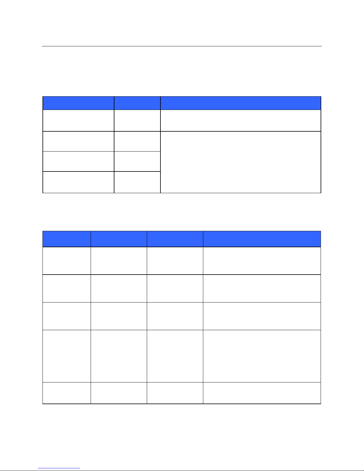
Guidance and Manufacturer’s Declaration: Electromagnetic Emissions
The equipment is intended for use in the electromagnetic environment specified in the table below. The customer or
the user of the equipment should ensure that it is used in such an environment.
Emissions Test Compliance Electromagnetic Environment: Guidance
RF Emissions
CISPR 11
RF Emissions
CISPR 11
Harmonic Emissions
IEC 61000-3-2
Voltage Fluctuations/
Flicker Emissions
IEC 61000-3-3
Group 2 The equipment must emit electromagnetic energy in order to
perform its intended function. Nearby electronic equipment may
be affected.
Class B The equipment is suitable for use in all establishments including
domestic establishments and those directly connected to the
public low-voltage power supply network that supplies buildings
Not Applicable
Not Applicable
used for domestic purposes.
Guidance and Manufacturer’s Declaration: Electromagnetic Immunity
The equipment is intended for use in the electromagnetic environment specified in the table below. The customer or
the user of the equipment should ensure that it is used in such an environment.
Emissions Test Compliance Compliance Level Electromagnetic Environment: Guidance
Electrostatic
discharge (ESD)
IEC 61000-4-2
Electrical fast
transient/burst
IEC 61000-4-4
Surge
IEC 61000-4-5
Voltage dips,
short
interruptions, and
voltage
variations on
power supply
input lines
IEC 61000-4-11
Power frequency
(50/60 Hz)
magnetic field
+/- 6 kV contact
+/- 8 kV air
+/- 2 kV for
power supply lines
+/- 1 kV for
input/output lines
+/- 1 kV differential
mode
+/- 2 kV common
mode
<5% UT
(>95% dip in UT)
for 0.5 cycle
40% UT
(60% dip in UT)
for 5 cycles
3 A/m 3 A/m Power frequency magnetic fields should be at
+/- 6 kV contact
+/- 8 kV air
Not Applicable
Not Applicable
Not Applicable
Floors should be wood, concrete, or ceramic
tile. If floors are covered with synthetic
material, the relative humidity should be at
least 30%.
levels characteristic of a typical location in a
typical commercial or hospital environment.
NOTE: UT is the AC Mains voltage prior to application of the test level.
xiv
Page 17
ELECTROMAGNETIC COMPATIBILITY (EMC)
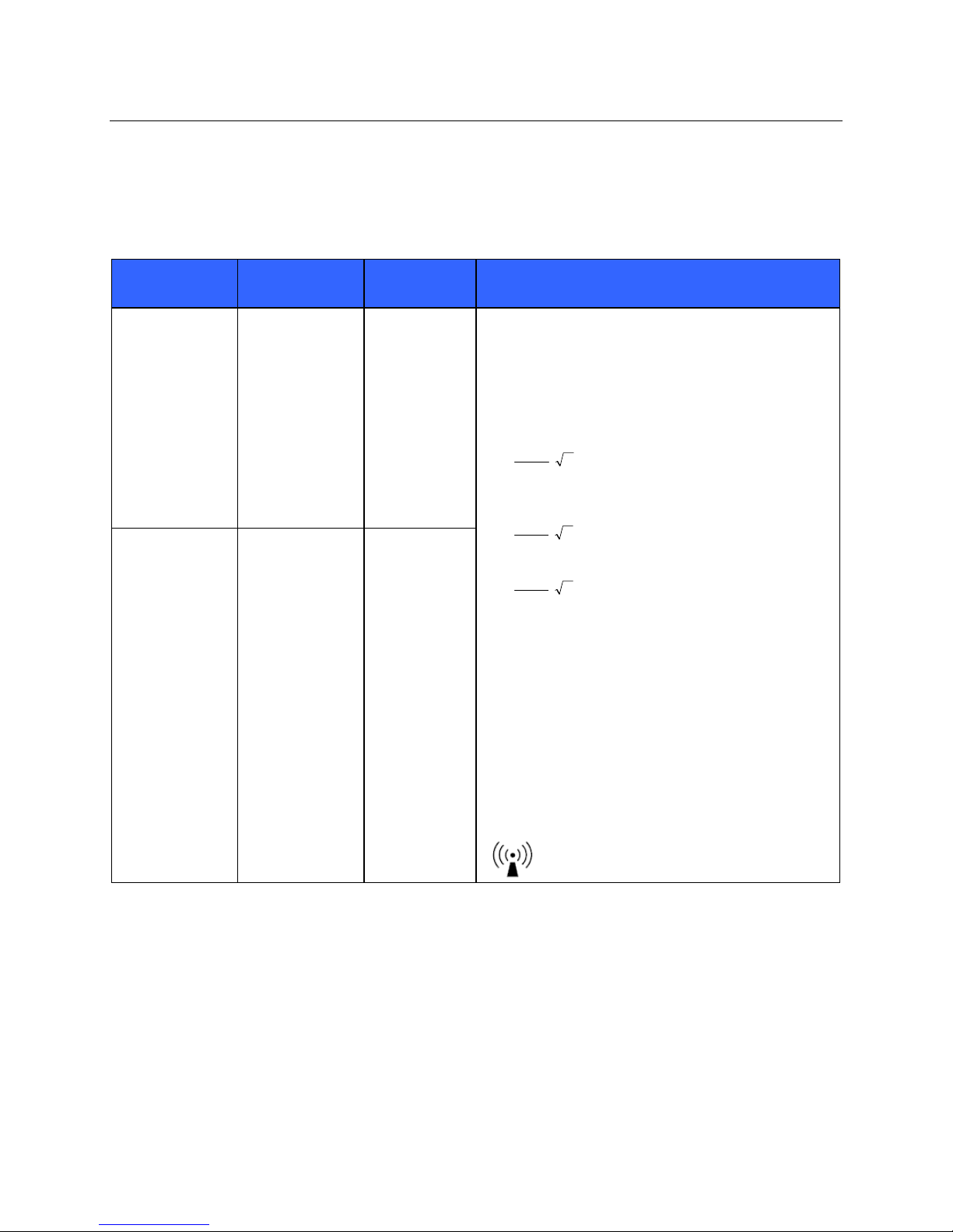
Guidance and Manufacturer’s Declaration: Electromagnetic Immunity
The equipment is intended for use in the electromagnetic environment specified in the table below. The customer or
the user of the equipment should ensure that it is used in such an environment.
Emissions Test
IEC 60601 Test
Level
Compliance
Level
Electromagnetic Environment: Guidance
Conducted RF
IEC 61000-4-6
Radiated RF
IEC 61000-4-3
3 Vrms
150 kHz to
80 MHz
3 V/m
80 MHz to
2.5 GHz
3 Vrms
150 kHz to
80 MHz
3 V/m
80 MHz to
2.5 GHz
Portable and mobile RF communications equipment
should be used no closer to any part of the equipment,
including cables, than the recommended separation
distance calculated from the equation applicable to the
frequency of the transmitter.
Recommended separation distance
5.3
d
Vrms
3
P
5.3
d
80 MHz to 800 MHz
P
mV
/3
7
d
Where P is the maximum output power rating of the
transmitter in watts (W) according to the transmitter
manufacturer and d is the recommended separation
distance in meters (m).
Field strengths from fixed RF transmitters, as
determined by an electromagnetic site survey
be less than the compliance level in each frequency
b
range
.
Interference may occur in the vicinity of equipment
marked with the following symbol:
800 MHz to 2.5 GHz
P
mV
/3
a
, should
a. Field strengths from fixed transmitters, such as base stations for radio (cellular/cordless) telephones and land mobile radios,
amateur radios, AM and FM radio broadcast, and TV broadcast cannot be predicted theoretically with accuracy. To assess
the electromagnetic environment due to fixed RF transmitters, an electromagnetic site survey should be considered. If the
measured field strength in the location in which the equipment is used exceeds the applicable RF compliance level above, the
equipment should be observed to verify normal operation. If abnormal performance is observed, additional measures may be
necessary, such as reorienting or relocating the equipment.
b. Over the frequency range 150 kHz to 80 MHz, field strengths should be less than [3] V/m.
xv
Page 18
ELECTROMAGNETIC COMPATIBILITY (EMC)
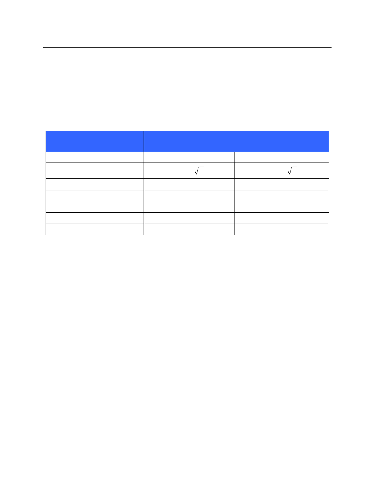
Recommended Separation Distances Between Portable and Mobile RF Communications
Equipment and the Equipment
The equipment is intended for use in the electromagnetic environment in which radiated RF disturbances are
controlled. The customer or the user of the equipment can help to prevent electromagnetic interference by
maintaining a minimum distance between portable and mobile RF communications equipment (transmitters) and the
equipment as recommended in the table below, according to the maximum output power of the communications
equipment.
Rated Maximum Output Power
of Transmitter W
150 KHz to 800 MHz 800 MHz to 2.5 GHz
Separation Distance According to Frequency of Transmitter (m)
0.01 0.1 m 0.2 m
0.1 0.4 m 0.7 m
1 1.2 m 2.3 m
10 4.0 m 7.0 m
100 12.0 m 23.0 m
Pd 2.1 Pd 3.2
For transmitters rated at a maximum output power not listed above, the recommended separation distance d in
meters (m) can be estimated using the equation applicable to the frequency of the transmitter, where P is the
maximum output power rating of the transmitter in watts (W) according to the transmitter manufacturer.
NOTE 1: At 800 MHz, the separation distance for the higher frequency range applies.
NOTE 2: These guidelines may not apply in all situations. Electromagnetic propagation is affected by the
absorption and reflection from structures, objects, and people.
xvi
Page 19

TABLE OF CONTENTS
INTRODUCTION SECTION 1
Manual Purpose ............................................................................................................................................................. 1
Audience ........................................................................................................................................................................ 1
Indications for Use ........................................................................................................................................................ 1
System Description ........................................................................................................................................................ 1
X12+ with Patient Cable, Figure 1-1, Front View ........................................................................................................ 2
LeadForm Patient Cable, Figure 1-2 ............................................................................................................................. 2
X12+ in Carrying Pouch, Figure 1-3 ............................................................................................................................. 3
Part Numbers ................................................................................................................................................................. 4
Specifications ................................................................................................................................................................ 5
OPERATION SECTION 2
Read Instructions ........................................................................................................................................................... 7
Battery Installation ........................................................................................................................................................ 7
Turning the X12+ On .................................................................................................................................................... 8
Turning the X12+ Off .................................................................................................................................................... 8
LCD Display Battery Voltage Indicator ........................................................................................................................ 8
Attaching the Patient Cable ........................................................................................................................................... 9
Patient ECG Hookup ..................................................................................................................................................... 9
Skin Preparation .............................................................................................................................................. 9
Positioning the Electrodes for 10-wire Hookup .......................................................................................................... 10
Using the Keypad ........................................................................................................................................................ 11
Main Menu .................................................................................................................................................................. 11
Top Level Menu Options ............................................................................................................................................. 12
Lead Check .................................................................................................................................................... 12
Checking Impedances ................................................................................................................................... 13
Displaying ECG Leads .................................................................................................................................. 13
Configuring the X12+ ................................................................................................................................................. 13
Setting the Transmission Channel Number ................................................................................................... 14
Setting the Number of Patient Cable Lead Wires ........................................................................................ 15
Setting Language ........................................................................................................................................... 15
Viewing Software Version Number .............................................................................................................. 15
Viewing Battery Voltage ............................................................................................................................... 15
Starting a Patient Transmission Session ...................................................................................................................... 16
Sending (Optional) Call Signals .................................................................................................................................. 16
Ending a Transmission Session ................................................................................................................................... 16
MAINTENANCE SECTION 3
Cleaning the X12+ and Accessories.. .......................................................................................................................... 17
Periodic Maintenance .................................................................................................................................................. 17
Disposal of Waste Materials ........................................................................................................................................ 17
x
vii
Page 20

TABLE OF CONTENTS
MESSAGES AND INFORMATION APPENDIX A
Table of Messages ....................................................................................................................................................... 19
System Information Log .............................................................................................................................................. 20
Serial and Part Number Location ................................................................................................................................ 20
CHANNEL ASSIGNMENTS APPENDIX B
600 MHz ...................................................................................................................................................................... 21
2500 MHz .................................................................................................................................................................... 22
915 MHz ...................................................................................................................................................................... 23
TRANSLATIONS APPENDIX C
Table of Translations ................................................................................................................................................... 25
xviii
Page 21

INTRODUCTION
SECTION 1
Manual Purpose
The X12+™ digital ambulatory transmitter user manual explains how to:
Acquire and transmit 12-lead ECG signals to a receiving device
Setup device configurations
NOTE: This manual may contain screen shots. Any screen shots are provided for reference only and are
not intended to convey actual operating techniques. Consult the actual screen in the host language for
specific wording.
Audience
This manual is written for clinical professionals who are expected to have a working knowledge of medical
procedures and terminology as required for monitoring cardiac patients.
Indications for Use
The device is indicated for use in a clinical setting by a physician, or by trained personnel who are acting on the
orders of a licensed physician. It is not intended as a sole means of diagnosis.
The device is indicated for use to acquire and output electrocardiographic data obtained during physiologic
stress exercise testing.
Indicated for use as a radiofrequency physiological signal transmitter, receiving and delivering real-time
acquisition and RF transmission of simultaneous 12-lead ECG data while allowing the patient to be ambulatory.
The device is indicated for use on adult populations, typically symptomatic.
The device is not intended to be used as a vital signs physiological monitor.
System Description
The X12+ represents state-of-the-art wireless electrocardiographic technology. It provides a means to acquire and
transmit 12-lead cardiac signals without direct connection to an electrocardiograph. Design innovations implemented in
the X12+ achieve real-time acquisition and RF transmission of simultaneous 12-lead ECG data with diagnostic quality
to a Mortara receiver module while allowing the patient to be ambulatory.
In addition, by using a very high monitoring frequency to transmit cardiac signals, the diagnostic bandwidth of the
signals is maintained.
The X12+ affords the patient complete freedom of movement. Unlimited range can also be obtained with the addition of
Mortara’s antenna network box(s).
The X12+ uses a single AA alkaline battery.
The following equipment is necessary to use the X12+:
One AA battery, 1.5V
Mortara receiver module with antennas
Patient cable
Antenna network
1
Page 22
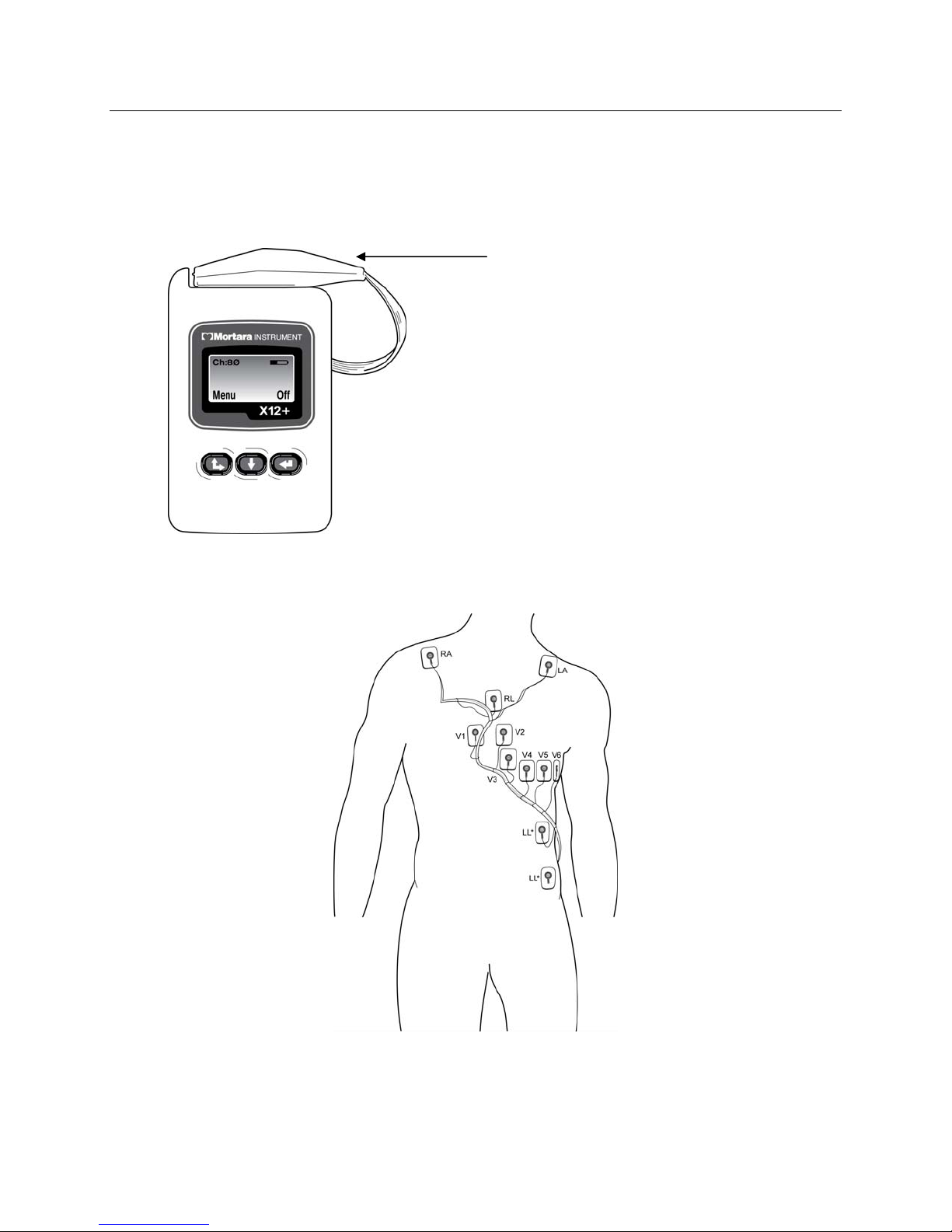
X12+ with Patient Cable
Figure 1-1, Front View
LeadForm Patient Cable
Figure 1-2
SECTION 1
Patient Cable
2
Page 23
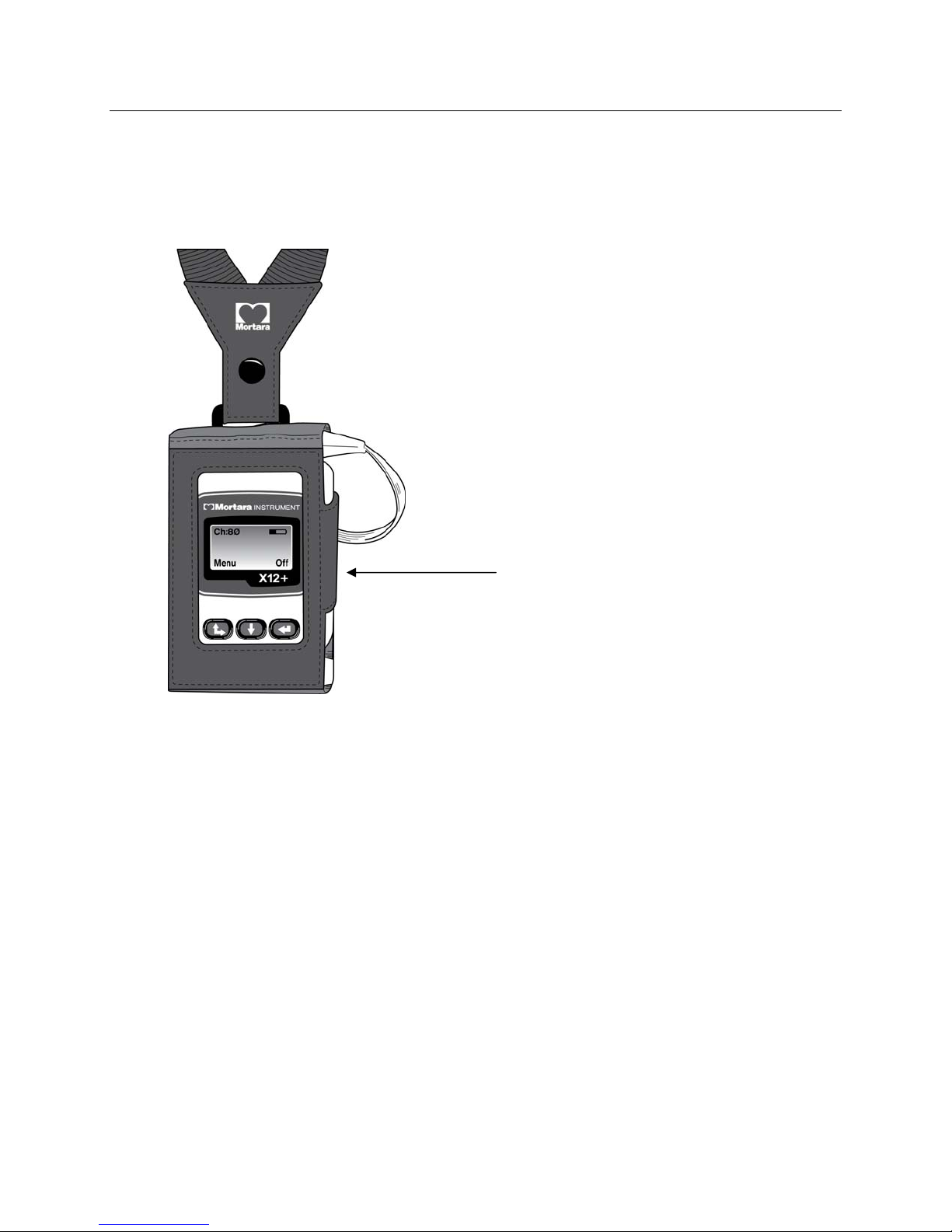
X12+ in Carrying Pouch
Figure 1-3
SECTION 1
Carrying Case with Neck Strap
3
Page 24

Part Numbers
Description Part Numbers
X12+ TRANSMITTER X12PLUS-XXX-XXXXX
X12+ BATTERY DOOR 8346-003-50
CARRY CASE & BELT ASSEMBLY H12+/X12+ 8485-020-50
PAT CBL 10WIRE LEADFORM AHA SNAP
PAT CBL 10WIRE IEC SNAP CINCH
PAT CBL 5WIRE AHA BANANA DO
PAT CBL 5WIRE IEC BANANA DO
PAT CBL 10WIRE LEADFORM XL AHA SNAP
PAT CBL 10WIRE LEADFORM XL AHA SNAP
HOOKUP KIT MONITORING 10E SINGLE 9294-009-50
SHORT FORM INSTR CARD X12+ (xxx = language) 9503-164-01-xxx
X12+ USER MANUALS 9515-164-50-CD
9293-017-50
9293-017-51
9293-025-50
9293-025-51
9293-026-50
9293-026-51
SECTION 1
To order additional supplies, contact a Mortara Instrument customer service representative.
4
Page 25

Specifications
SECTION 1
Feature
Instrument Type 12-lead ECG digital transmitter
Input Channels Continuous 12-lead signal acquisition and transmission
ECG Leads Transmitted I, II, III, aVR, aVL, aVF, V1, V2, V3, V4, V5 and V6
Frequency Range* 608.48 MHz to 631.52 MHz or
Special Functions Lead impedance check, ECG display, lead fail, battery
Defibrillator Protection Complies with AAMI standards and IEC 60601-2-25
Number of Channels
Function Keys Up/right, down, and enter keys for on/off and menu
Device Classification Type CF, battery operated
Weight 4 oz. (125 g) without battery
Dimensions 2.5 x 3.5 x .98” (64 x 91 x 25 mm)
Specifications
904.76 MHz to 925.16 MHz or
2400.96 MHz to 2482.56 MHz
notification, multi-purpose call; 10-wire, 5-wire, and 4-wire
options
256 user selectable
navigation; call button during transmission
Battery 1 AA alkaline, 24-hour typical life
*Operating frequency range is dependent on the X12+ part number.
5
Page 26

SECTION 1
6
Page 27
OPERATION
Read Instructions before Operating this Device
The user is cautioned that any changes or modifications not expressly approved by Mortara Instrument, Inc.
could void the user’s authority to operate this device.
This device complies with part 15 of the FCC rules. Operation is subject to the following conditions:
1. This device may not cause harmful interference, and
2. This device must accept any interference received, including interference that may cause undesired operation.
The X12+ must be used solely on the premises of healthcare facilities (see Part 15, section 15.242a).
A health care facility operating the X12+ must coordinate with the directors of existing nearb y TV
stations and radio astronomy observatories to ensure compatible use. Minimum separation distances
from such facilities may apply. It may be necessary to obtain written authorization from such facilities
prior to installation and use of the X12+ (Part 15, section 15.242d,e).
Operating frequency ranges are 608.48 to 631.52 MHz, 904.76 to 925.16 MHz, or 2400.96 to 2482.56 MHz.
FCC ID: HJR-X12-600-15 FCC ID: HJR-X12P-915 FCC ID: HJR-X12P-2500
This device is defibrillator protected in compliance with AAMI standards and IEC 60601-2-25.
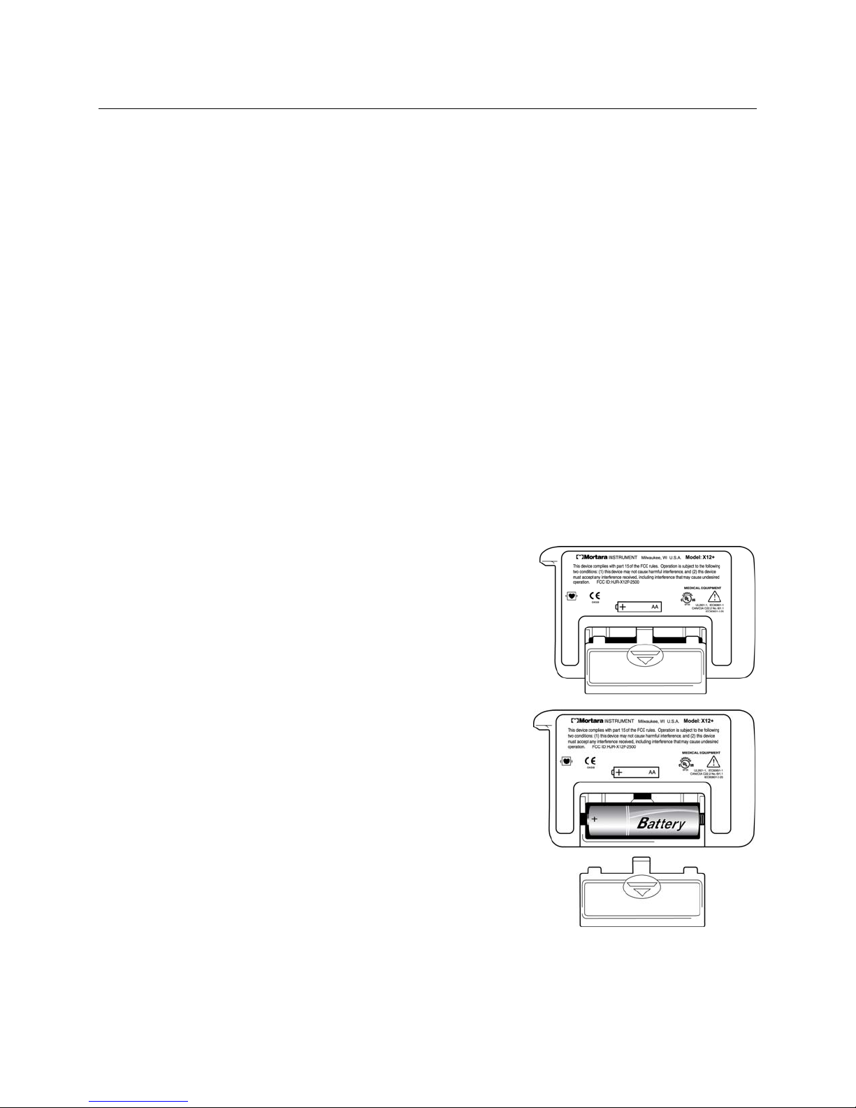
Battery Installation
The battery compartment is accessible via the battery door.
1. Position the X12+ with its back facing you to open the
battery door.
2. Press down on the battery door arrow symbol and slide the
battery door out.
3. Insert one AA alkaline battery into the battery compartment.
Align the positive (+) and negative (-) indicators of the battery
with the designators in the battery compartment.
4. To close the battery door, replace the battery door on the X12+
and slide the door in until it snaps into place.
NOTES: AA alkaline batteries are recommended. The
typical life of one AA alkaline battery is 30 hours.
SECTION 2
7
Page 28
Turning the X12+ On
The X12+ will power up as soon as a battery with a minimum of 1.0 volts has been inserted into the battery
compartment. If the X12+ was turned off after its last use, the user has two options to power the X12+ on:
1. Remove and re-insert the AA alkaline battery, or
2. Press Up/Right
The X12+ will power up and display the main LCD menu within three seconds.
Turning the X12+ Off
The user has two options to power the X12+ off:
1. Remove the battery, or
SECTION 2
2. Press and hold
Enter for a period of three seconds
a. A prompt will appear in the LCD display
b. Press Up/Right to highlight Yes
c. Press Enter to select
NOTE: The user has three seconds to select yes or no or the prompt menu will be replaced by the
main menu.
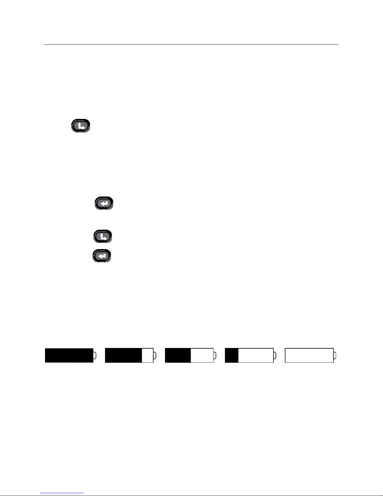
LCD Display Battery Voltage Indicator
The X12+ is powered with a single AA alkaline battery that requires a minimum of 1.0 volts to operate.
When the battery contains sufficient voltage, the LCD main menu will display a picture representing the current
battery voltage in increments of 100%, 75%, 50%, 25%, or 0%. If a battery with unknown voltage is inserted and
the LCD menu does not appear, insert a new battery.
100%
An option to display the actual battery voltage is also available in the configuration menu and will be explained later
in this section.
NOTE: If battery voltage is below 1.0 volts, the X12+ will not power on. Insert a new AA alkaline battery
to continue operation.
When the battery indicator shows a voltage of 25%, the battery should be discarded and a new battery
should be inserted.
75% 50% 25% Low Battery
8
Page 29
SECTION 2
Attaching the Patient Cable
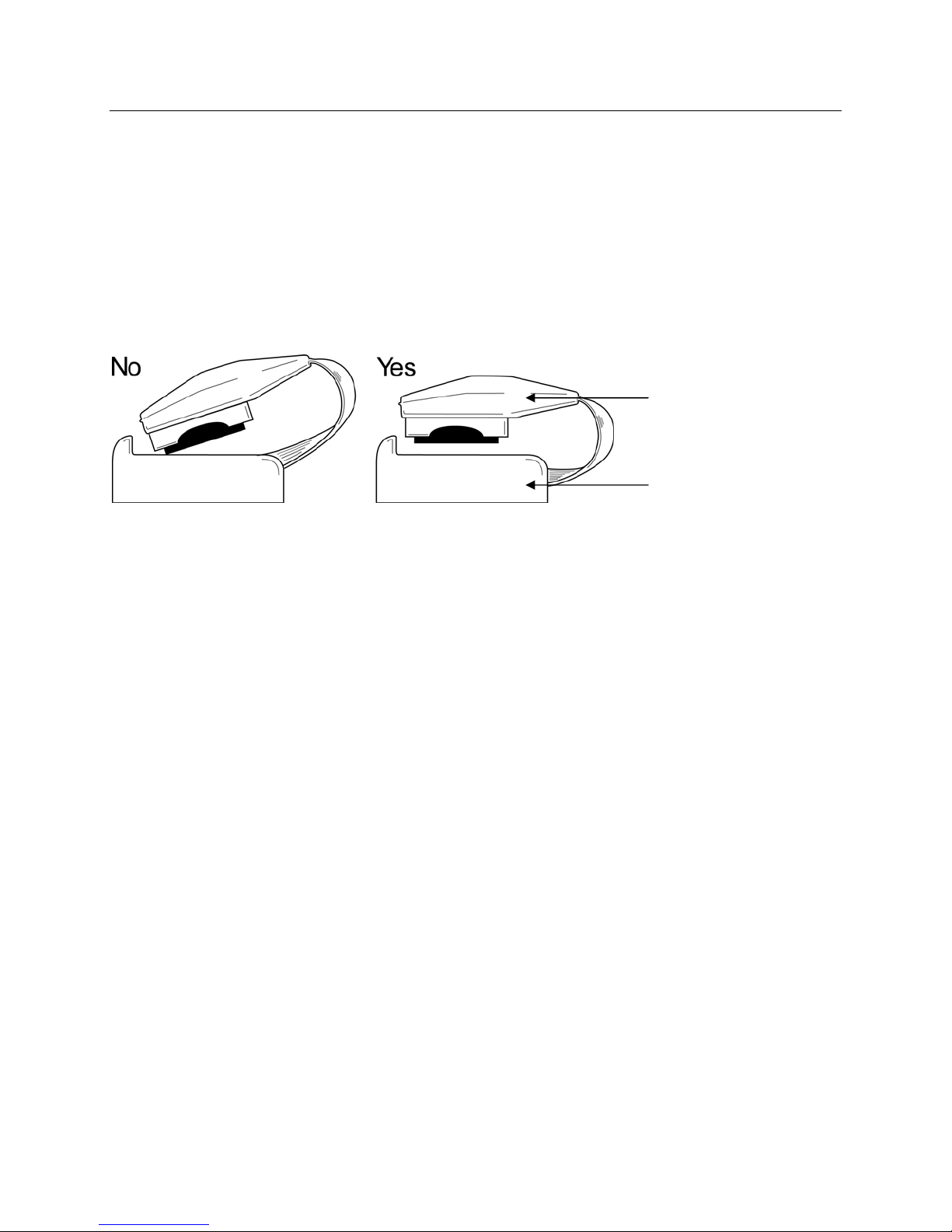
The LeadForm patient cable consists of a connector block, a main cable, and lead wires connected to the main cable.
Each lead wire terminates in a snap connector. The lead wires are positioned on the main cable to follow the
contour of the torso.
Insert the connector block into the input connector on the top of the X12+.
NOTE: Be careful to insert the connector block parallel to the input connector.
Connector Block
Input Connector
Patient ECG Hookup
Skin Preparation
Skin preparation is important to perform before electrode attachment to help ensure good signal quality when
transmitting patient data. Poor skin-electrode contact may cause noise or artifact which can affect the analysis of the
ECG data. Low amplitude signals may also be the result of poor skin-electrode contact.
To prepare the skin
1. Identify the electrode sites on the torso by referring to Positioning the Electrodes for 10-wire Hookup.
2. Remove any hair from the electrode sites using a razor.
3. Wipe oils from the electrode sites with an alcohol prep pad.
4. Remove any dead skin from the electrode sites with an abrasive pad. Two to three moderate rubs at each site
should be sufficient.
9
Page 30
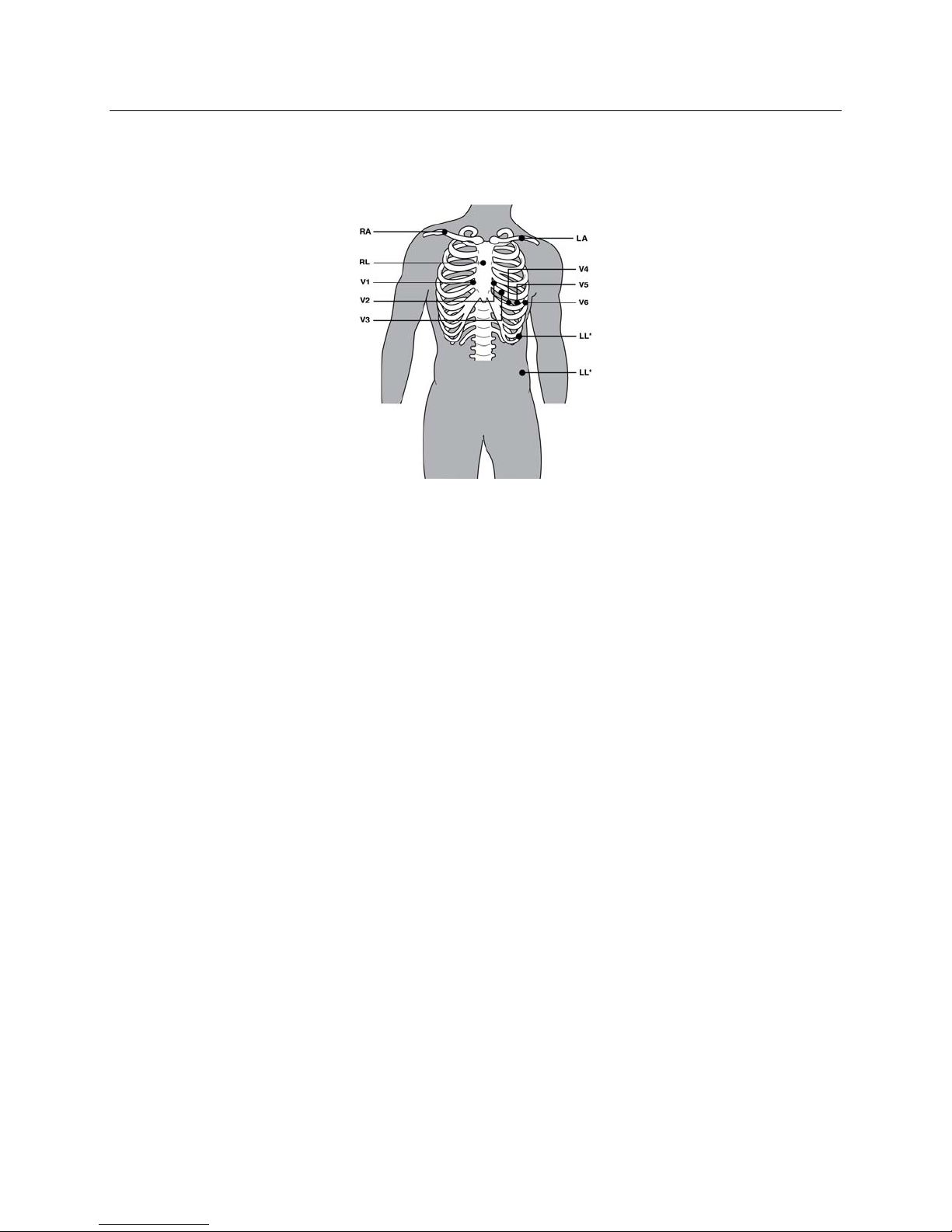
Positioning the Electrodes for 10-wire (12-lead) Hookup
SECTION 2
Limb Electrodes
AAMI IEC
RA R
LA L
RL N
LL F
Precordial Electrode
AAMI IEC
V1 C1
V2 C2
V3 C3
V4 C4
V5 C5
Placement
Right clavicle as shown
Left clavicle as shown
Reference or ground lead, placed to maximize patient comfort
Lower left side of body, as close to hip as possible, on the iliac crest (original
Mason-Likar position) or lowest rib on the left side of chest (modified MasonLikar position)
Placement
Fourth intercostal space at the right sternal border
Fourth intercostal space at the left sternal border
Midway between V2 and V4
Fifth intercostal space at the left midclavicular line
Anterior axillary line on same horizontal level as V4
V6 C6
Mid-axillary line on the same horizontal level as V4 and V5
NOTE AND CAUTION: Placement of the Left Leg (LL)* electrode in the original Mason-Likar position
increases the similarity of the acquired ECG with a standard 12-lead ECG and is therefore recommended;
however, clothing may interfere with this position and increase the amount of artifact. The modified
position may decrease the sensitivity of inferior ECG leads and cause axis shift with respect to the standard
12-lead ECG. Accurate skin preparation and suitable clothing are the most important factors in excessive
artifact prevention.
NOTE: The Right Leg (RL) electrode may be positioned in any location least subject to motion artifact
according to clinician preference and specific test requirements.
10
Page 31
SECTION 2
When the electrode sites have been identified and prepped, remove the clear electrode covering and apply an
electrode to each of the sites. Secure each electrode by exerting slight pressure around the outer edge and inner ring
of the electrode.
To connect the lead wires, begin with connecting the LL lead wire (Red – labeled LL or F) to the LL electrode.
Connect the next lead wire on the cable to the next electrode. Continue connecting the snap connectors to the
electrodes as positioned on the main cable.
NOTE: QRS morphology may be slightly different from a standard 12-lead ECG due to torso located limb
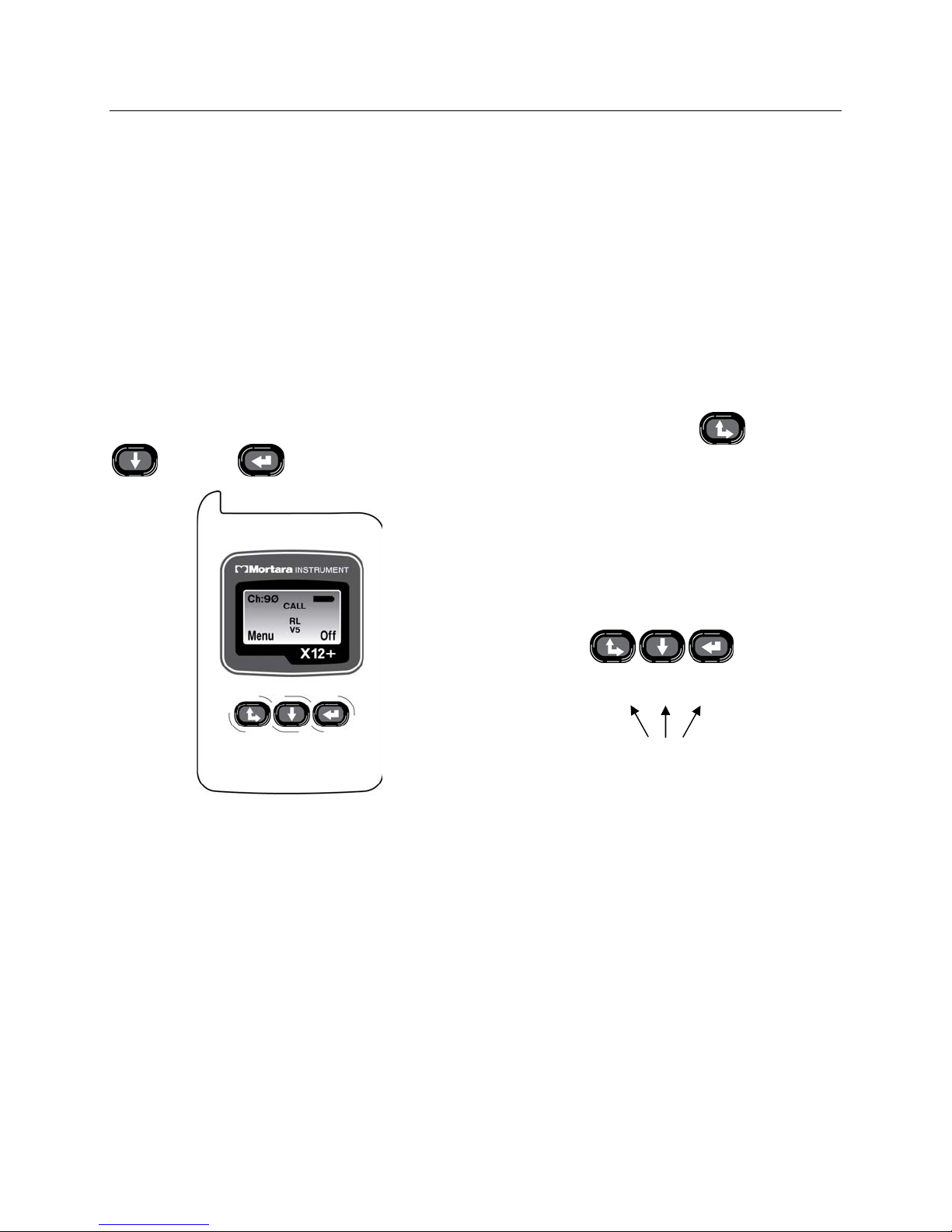
Using the Keypad
The keypad is located on the front, lower portion of the X12+. Three keys are available for navigating through the
electrode placement.
LCD menu screens, for powering the X12+ on/off, and for sending calls during transmission:
Up/Right,
Down, and Enter.
Menu Off
Up/Right Down Enter
Call = Any Key
Main Menu
The X12+ main LCD menu displays the following information.
Ch:XX = Transmission channel
Battery Symbol = 100%, 75%, 50%, or 25% battery charge
Menu = Label over the Up/Right key for access to menu options
Off = label over the Enter key to power the X12+ off
RL, RA, LL, LA, V1, V2, V3, V4, V5, and/or V6 = Leads in fail
To send a CALL signal, press any one of the three keypad keys. A CALL indicator will appear on the LCD display
to notify the user that a call signal has been transmitted.
CALL = a call signal has been transmitted
11
Page 32
SECTION 2
Top Level Menu Options
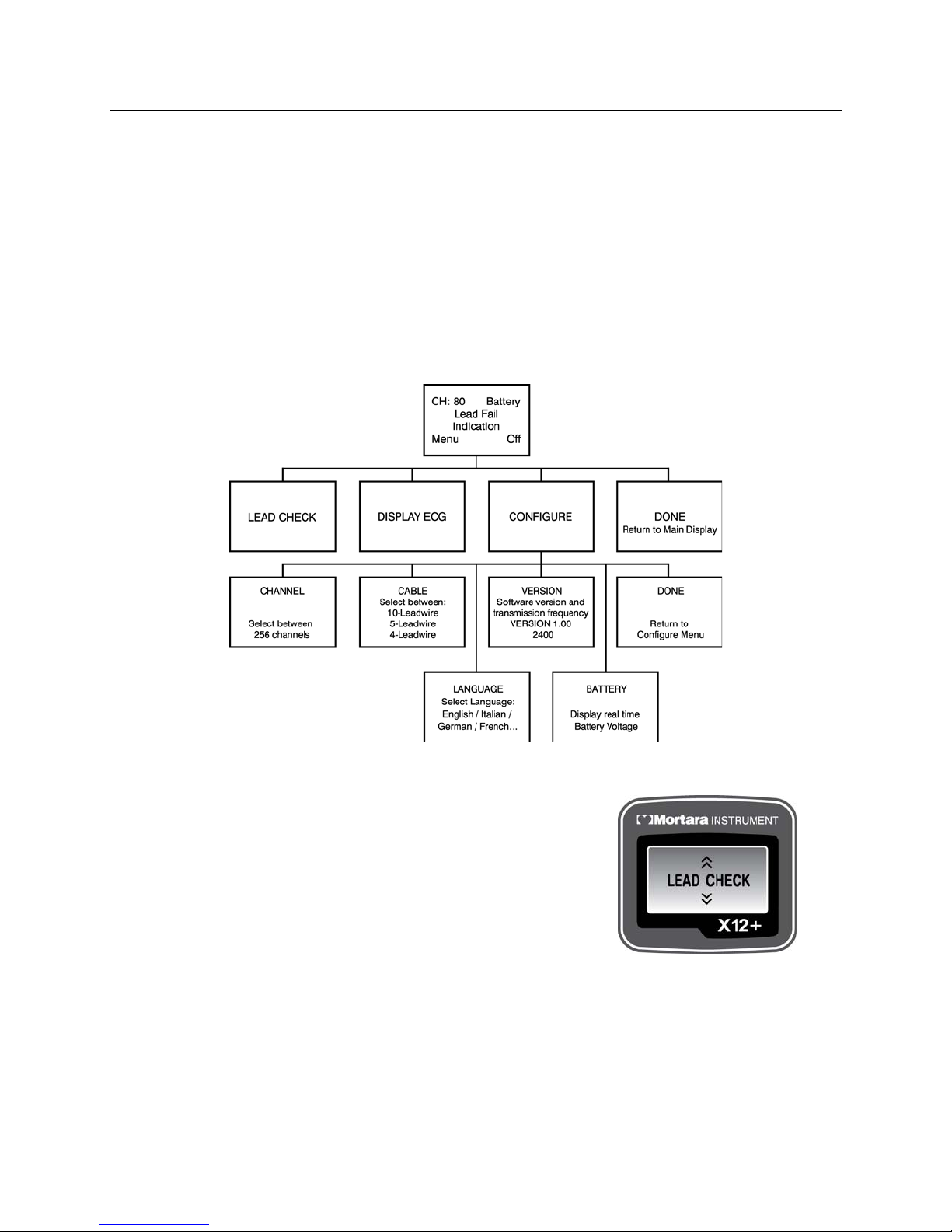
To select menu options, press and hold Up/Right for approximately three seconds. Use Up/Right and Down to
scroll and Enter to select. The top level menu includes:
LEAD CHECK
DISPLAY ECG
CONFIGURE
An operational flowchart of menu options depicts the flow of functionality using the three keys.
DONE
Lead Check
LEAD CHECK, DISPLAY ECG, and CONFIGURE are performed
prior to starting a new patient.
LEAD CHECK, DISPLAY ECG, and DONE are typically selected
prior to each new session.
12
Page 33
SECTION 2
Checking Impedances
LEAD CHECK is the first option displayed on the LCD screen after patient hookup and is a valuable tool for
verifying and optimizing signal quality before starting a patient session.
From the main menu, use Down or Up/Right to scroll to LEAD CHECK. Press Enter to select.
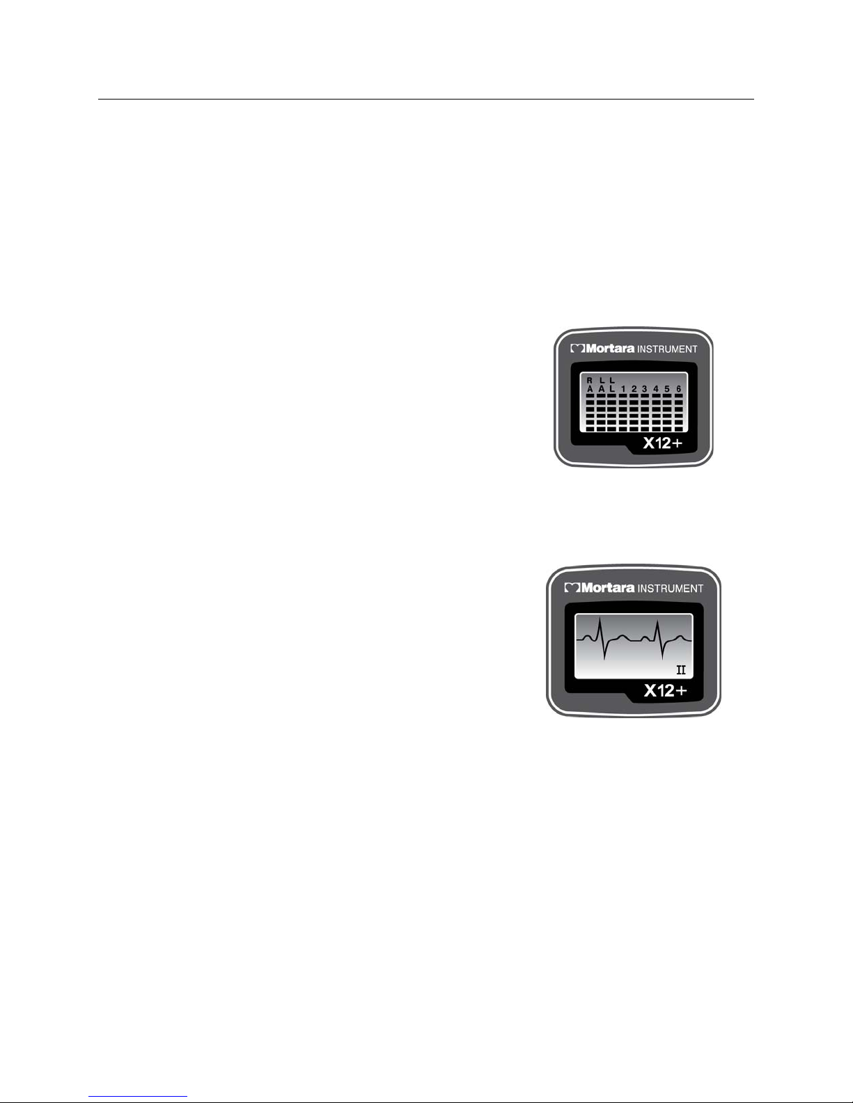
A graph depicting the impedance measured at the right arm (RA), left arm (LA), left leg (LL), and V1 through V6
electrodes is displayed from left to right in vertical columns on the screen. The higher the bar, the better the skin-toelectrode contact.
For good quality transmissions, the bars should be at least 4 bars high.
A full-bar graph (6 bars) means optimal high quality and good
electrode contact. A low-bar graph means poor quality and high
electrode impedance. Skin preparation should be checked for
improvement and, if necessary, the electrode(s) should be replaced.
Once acceptable impedance levels are verified, press any of the three
keys to return to the top level menu.
Displaying ECG Leads
DISPLAY ECG is used to visually inspect leads I, II, III, V1, V2, V3, V4, V5, and V6 before starting a
transmission session. Check the signal quality and lead amplitude for each lead.
From the main menu, use Down or Up/Right to scroll to DISPLAY
ECG. Press Enter to select.
Lead I is the first lead displayed on the screen. Use Down or
Up/Right to scroll from lead to lead.
After visual verification of all leads, press Enter to return to the top
level menu.
Use Down or Up/Right to scroll to Exit. Press Enter to return to the
main menu.
Configuring the X12+
CONFIGURE is used to set the channel number, the number of patient cable lead wires, and the language defaults.
This menu is also used to display the software version number and current battery voltage. Settings are typically set
before the initial patient session and do not need to be set on a per patient basis.
From the main menu, use Down or Up/Right to scroll to CONFIGURE. Press Enter to select.
13
Page 34
SECTION 2
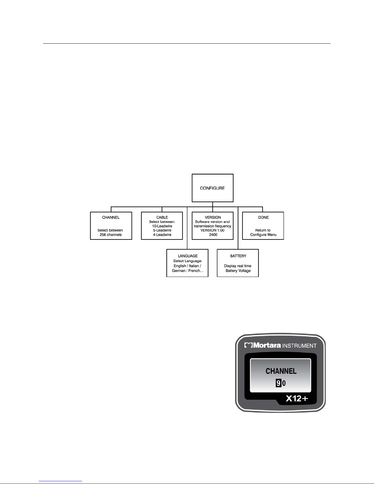
The CONFIGURE menu includes:
CHANNEL
CABLE
LANGUAGE
VERSION
BATTERY
DONE
Use Down or Up/Right to scroll through the CONFIGURE menu options. Press Enter when the desired option is
displayed. Select DONE and press Enter to return to the top level menu. Scroll to DONE and press Enter to
return to the main menu.
The operational flowchart of CONFIGURE menu options depicts the flow of functionality using the three keys.
Setting the Transmission Channel Number
The X12+ transmits the patient’s cardiac signals to the electrocardiograph using a specific channel number.
CHANNEL is used to enter the optimal transmission channel number before starting a patient session. The user
may choose from any of 256 channels. If ECG signal loss occurs, the transmission channel can be changed.
From the main menu, use Down or Up/Right to scroll to CHANNEL.
Press Enter to select.
To enter the channel number, move the cursor to the right or left
alphanumeric character field by pressing Up/Right. To move the cursor
one letter or digit at a time, press Down. When the cursor reaches the
end of the characters it will wrap to the beginning.
When finished, press Enter to exit the CHANNEL menu.
NOTE: When entering the channel number, the down arrow key
is used to change the characters. The cursor cannot be moved in
the up direction.
14
Page 35

SECTION 2
Setting the Number of Patient Cable Lead Wires
CABLE is used to set the number of lead wires for the patient cable.
From the CONFIGURE menu, use Down or Up/Right to scroll to CABLE. Press Enter to select. The CABLE
menu includes:
4 lead wire
5 lead wire
10 lead wire
Use Down or Up/Right to scroll to the desired option and press Enter. When finished, press Enter to exit the
CABLE menu.
NOTE: When a 4-wire or 5-wire cable is selected, only the limb leads (and a V label with the 5-wire
cable) will appear in LEAD CHECK, DISPLAY ECG, and lead fail messages.
Setting Language
LANGUAGE is used to select the language displayed in the main menu and all sub-menu options.
From the CONFIGURE menu, use Down or Up/Right to scroll to LANGUAGE. Press Enter to select. When
finished, press Enter to exit the LANGUAGE menu.
Viewing Software Version Number
VERSION displays the current software version installed in the X12+.
From the CONFIGURE menu, use Down or Up/Right to scroll to VERSION. Press Enter to select and view the
current software. When finished, press Enter to exit the VERSION menu.
Viewing Battery Voltage
BATTERY displays the voltage of the battery currently installed in the X12+.
From the CONFIGURE menu, use
current battery voltage. When finished , press Enter to exit the BATTERY menu.
Down or Up/Right to scroll to BATTERY. Press Enter to select and view the
15
Page 36
SECTION 2
Starting a Patient Transmission Session
1. Hookup the patient.
2. Ensure that there is an AA alkaline battery in the battery compartment (see note below).
3. Press Up/Right to turn the X12+ on (if not already powered on by battery insertion).
4. Use LEAD CHECK to check the electrode-to skin-impedan ces and verify patient hookup quality as explained
in this section.
5. Use DISPLAY ECG to verify the amplitude and signal quality of each ECG lead as explained in this section.
6. Exit and return to the main menu.
NOTE: If battery voltage is below 1.0 volts, the X12+ will not power on. Insert a new AA alkaline battery
to continue operation.
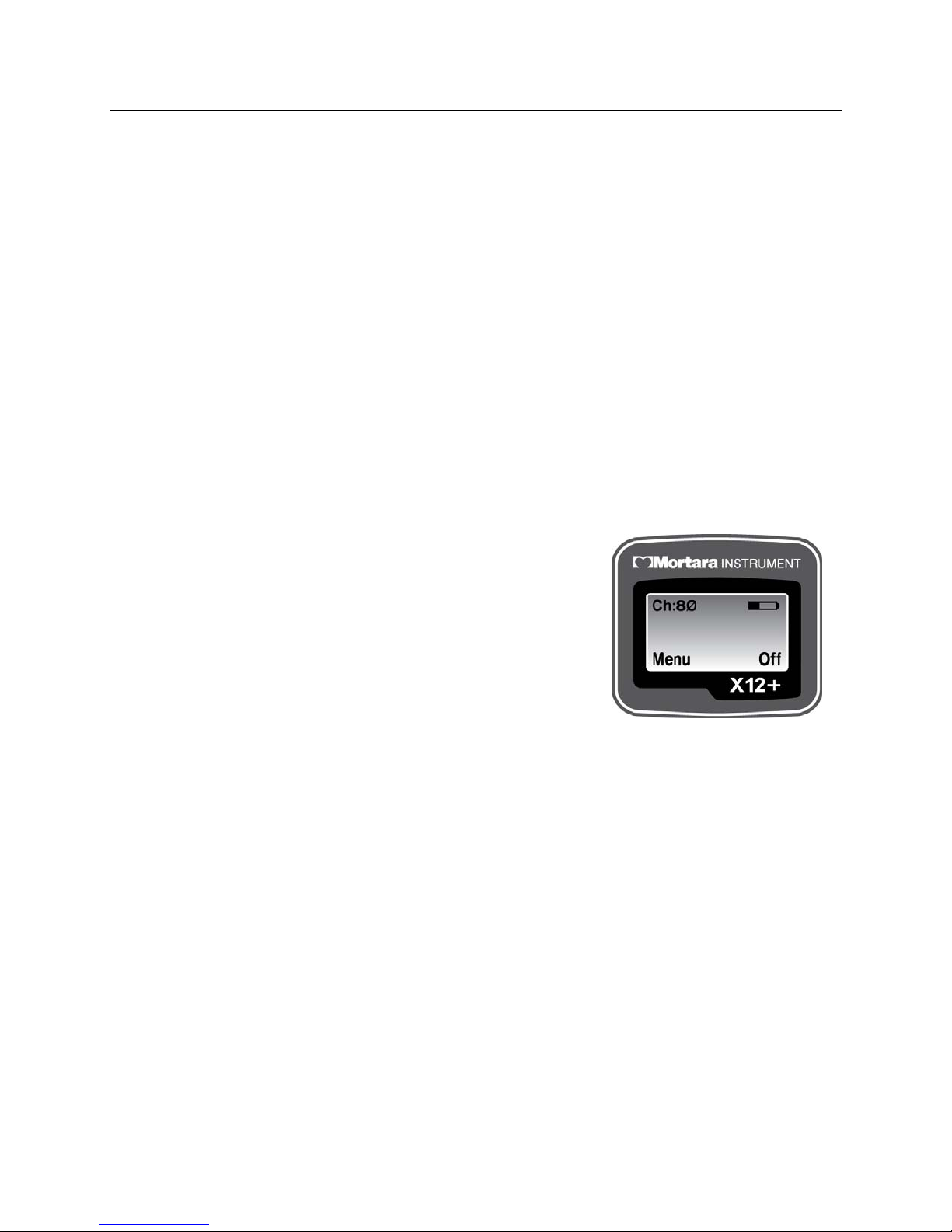
During normal operation, Ch: xx (channel number) and battery indicator are continuously displayed on the LCD.
If the battery is removed during a transmission session, the X12+ stops
transmitting. A battery must be inserted to continue operation.
NOTE: If a lead fail condition occurs during operation, the
appropriate lead fail indicator(s) is displayed in the center of the
LCD display.
Refer to Appendix A, Messages and Information for information
on lead fail messages.
Sending (Optional) Call Signals
During the patient data transmission session, the patient may be instructed to transmit call signals from the X12+ to
a receiving device for monitoring purposes.
To send a call signal, press any one of the three keys on the X12+. The CALL message is displayed in the main
menu on the LCD to inform the user that a call was sent.
Ending a Transmission Session
At the end of the patient session, the X12+ can be turned off.
16
Page 37

MAINTENANCE
SECTION 3
Cleaning the X12+ and Accessories
1. Remove cables and disconnect power source from device before cleaning.
2. Wash the carry case by hand with fabric detergent and then air dry. Do not machine dry the case.
3. For general cleaning, use a soft, lint-free cloth lightly moistened with a mild soap and water solution. W ipe and
air dry.
Do use clean, lint-free cloth
Don’t use alcohol or solvents
Don’t use abrasive cleaners or materials
4. For disinfecting, wipe exterior with a soft, lint-free cloth using a solution of Sodium Hypochlorite (10%
household bleach and water solution) minimum 1:500 dilution (minimum 100 ppm free chlorine) and maximum
1:10 dilution as recommended by the AP IC Guidelines for Selection and Use of Disinfectant s.
5. Use caution with excess liquid as contact with metal parts may cause corrosion.
6. Do not immerse cable ends or lead wires; immersion can cause metal corrosion.
7. Do not use excessive drying techniques such as forced heat.
WARNING: Prevent liquid from penetrating the device and do not attempt to clean/disinfect the device or
patient cables by submerging into a liquid, autoclaving, or steam cleaning. Never expose cables to strong
ultra-violet radiation. Do not sterilize the device or ECG cable with Ethylene Oxide (EtO) gas.
Periodic Maintenance
Check the X12+ and the ECG cable before each use to ensure they are not damaged or broken.
1. Patient Cable Maintenance:
• Check patient cables for cracks or breakage prior to use
• Clean the cable with a germicidal solution that does not contain alcohol
• Alcohol will cause hardening and can introduce cracks
• Don’t use tape on the patient cable; tape residue will cause hardening and can in troduce cracks
• Patient cables should be stored by looping them loosely. Don’t pull or stretch the cables; don’t
wrap cables tightly
• Replace patient cables periodically (depending on use and care)
2. Exterior Visual Inspection:
• Check connectors for loose, bent, or corroded contact points
• Inspect covers for warping, surface damage, or missing hardware
• Check for any other form of damage
Disposal of Waste Materials
The X12+ needs one alkaline battery and disposable monitoring electrodes. Disposal must be in accordance with
the following procedures:
Battery: applicable disposal or recycling standards
Electrodes: normal waste
17
Page 38

SECTION 3
18
Page 39
MESSAGES AND INFORMATION
APPENDIX A
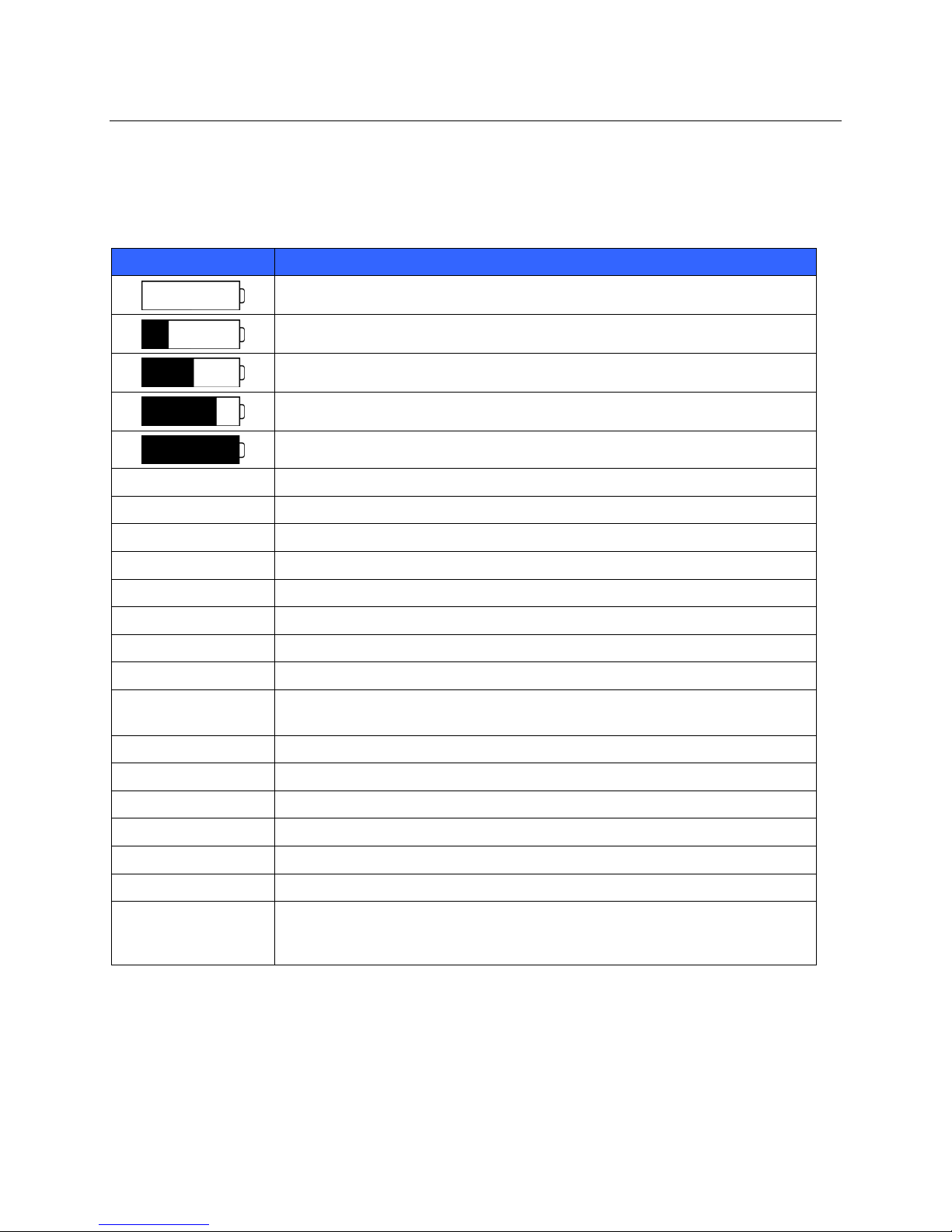
The following table describes messages that are displaye d on the X1 2+ du r i ng pat ie nt h ooku p an d tra ns mission.
Table of Messages
Message Solution
Battery power is low. Replace existing battery with a fully charged battery.
Battery power is at 25%.
Battery power is at 50%.
Battery power is at 75%.
Battery power is at 100% (fully charged).
CALL
A call signal has been transmitted.
CH:XX
MENU
OFF
‘RA’
‘RL’
‘LA’
‘LL’
A combination of
‘RA/…/LL’
‘V1’
‘V2’
‘V3’
‘V4’
‘V5’
‘V6’
A combination of
‘V1, V2, V3, V4, V5,
V6’
The transmission channel that has been set for this unit.
Label over the Up/Right arrow key that indicates access to menu options
Label over the Enter key that indicates powering the unit of f.
RA fail. Check if the lead wire is off or the electrode needs to be replaced.
RL fail. Check if the lead wire is off or the electrode needs to be replaced.
LA fail. Check if the lead wire is off or the electrode needs to be replaced.
LL fail. Check if the lead wire is off or the electrode needs to be replaced.
More than one limb lead fail or all leads fail. Check the lead wires and electrodes.
V1 fail. Check if the lead wire is off or the electrode needs to be replaced.
V2 fail. Check if the lead wire is off or the electrode needs to be replaced.
V3 fail. Check if the lead wire is off or the electrode needs to be replaced.
V4 fail. Check if the lead wire is off or the electrode needs to be replaced.
V5 fail. Check if the lead wire is off or the electrode needs to be replaced.
V6 fail. Check if the lead wire is off or the electrode needs to be replaced.
More than one chest lead fail. Check the lead wires and electrodes.
19
Page 40
APPENDIX A
The following system information log is provided for your convenience. You need this information if your system
needs servicing. Be sure to update the information log when you add options or your system has been serviced.
Record the model and serial number of all components, dates of removal and/or replacement, and the name of the
vendor from whom the component was purchased and/or installed.
In addition to having records of this information, the system information provides a warranty record of when your
system was placed in service.
System Information Log
Manufacturer:
Mortara Instrument, Inc.
7865 N. 86th St.
Milwaukee, WI 53224
Product Information:
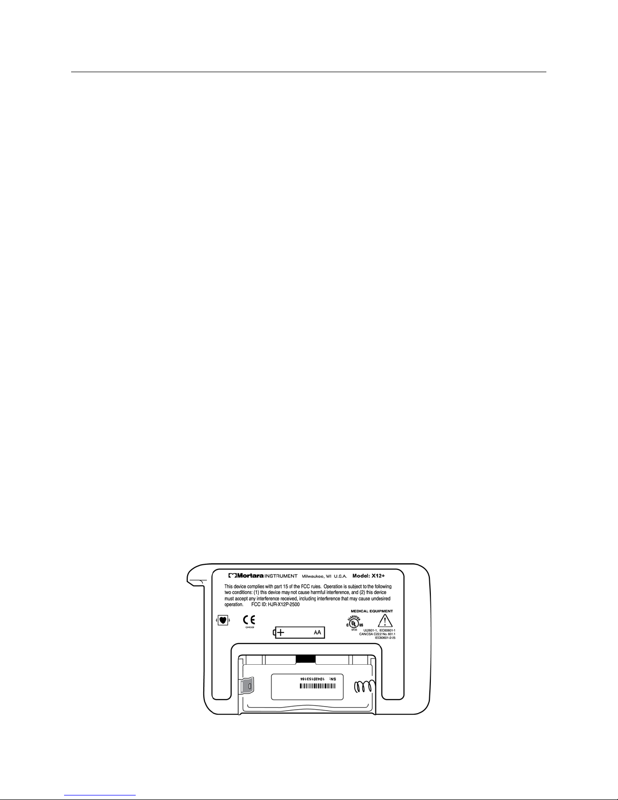
Serial and Part Number Location
For questions and service information, have serial number and part number available when calling.
The serial number (SN) and part number (REF) are found under the battery, in the battery compartment on the
backside of the unit similar to the one pictured below.
Figure A
Telephone Numbers:
Domestic: 800-231-7437
European: +39-51-6650-701
Sales Department: 800-231-7437
Service Department: 888-MORTARA
Name of Unit/Product: ____________________
Date of Purchase: ___/___/_____
Purchased Unit From: ____________________
Serial Number: _______________
Software Version: _____________
20
Page 41
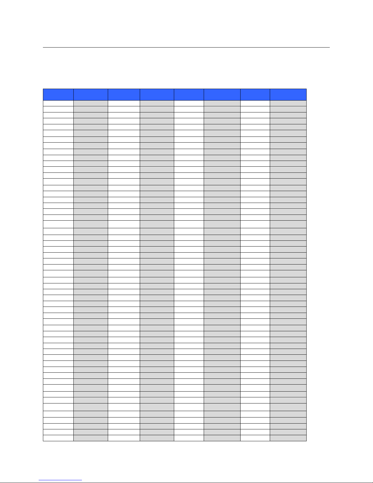
CHANNEL ASSIGNMENTS
X12+600 Channel Assignments
Includes reference to UHF TV channel occupying the same frequency range.
CH#
00 608.48 40 614.48 80 620.48 C0 626.48
01 608.56 41 614.56 81 620.56 C1 626.56
02 608.64 42 614.64 82 620.64 C2 626.64
03 608.72 43 614.72 83 620.72 C3 626.72
04 608.8 44 614.8 84 620.8 C4 626.8
05 608.88 45 614.88 85 620.88 C5 626.88
06 608.96 46 614.96 86 620.96 C6 626.96
07 609.04 47 615.04 87 621.04 C7 627.04
08 609.12 48 615.12 88 621.12 C8 627.12
09 609.2 49 615.2 89 621.2 C9 627.2
0A 609.28 4A 615.28 8A 621.28 CA 627.28
0B 609.36 4B 615.36 8B 621.36 CB 627.36
0C 609.44 4C 615.44 8C 621.44 CC 627.44
0D 609.52 4D 615.52 8D 621.52 CD 627.52
0E 609.6 4E 615.6 8E 621.6 CE 627.6
0F 609.68 4F 615.68 8F 621.68 CF 627.68
10 609.76 50 615.76 90 621.76 D0 627.76
11 609.84 51 615.84 91 621.84 D1 627.84
12 609.92 52 615.92 92 621.92 D2 627.92
13 610 53 616 93 622 D3 628
14 610.08 54 616.08 94 622.08 D4 628.08
15 610.16 55 616.16 95 622.16 D5 628.16
16 610.24 56 616.24 96 622.24 D6 628.24
17 610.32 57 616.32 97 622.32 D7 628.32
18 610.4 58 616.4 98 622.4 D8 628.4
19 610.48 59 616.48 99 622.48 D9 628.48
1A 610.56 5A 616.56 9A 622.56 DA 628.56
1B 610.64 5B 616.64 9B 622.64 DB 628.64
1C 610.72 5C 616.72 9C 622.72 DC 628.72
1D 610.8 5D 616.8 9D 622.8 DD 628.8
1E 610.88 5E 616.88 9E 622.88 DE 628.88
1F 610.96 5F 616.96 9F 622.96 DF 628.96
20 611.04 60 617.04 A0 623.04 E0 629.04
21 611.12 61 617.12 A1 623.12 E1 629.12
22 611.2 62 617.2 A2 623.2 E2 629.2
23 611.28 63 617.28 A3 623.28 E3 629.28
24 611.36 64 617.36 A4 623.36 E4 629.36
25 611.44 65 617.44 A5 623.44 E5 629.44
26 611.52 66 617.52 A6 623.52 E6 629.52
27 611.6 67 617.6 A7 623.6 E7 629.6
28 611.68 68 617.68 A8 623.68 E8 629.68
29 611.76 69 617.76 A9 623.76 E9 629.76
2A 611.84 6A 617.84 AA 623.84 EA 629.84
2B 611.92 6B 617.92 AB 623.92 EB 629.92
2C 612 6C 618 AC 624 EC 630
2D 612.08 6D 618.08 AD 624.08 ED 630.08
2E 612.16 6E 618.16 AE 624.16 EE 630.16
2F 612.24 6F 618.24 AF 624.24 EF 630.24
30 612.32 70 618.32 B0 624.32 F0 630.32
31 612.4 71 618.4 B1 624.4 F1 630.4
32 612.48 72 618.48 B2 624.48 F2 630.48
33 612.56 73 618.56 B3 624.56 F3 630.56
34 612.64 74 618.64 B4 624.64 F4 630.64
35 612.72 75 618.72 B5 624.72 F5 630.72
36 612.8 76 618.8 B6 624.8 F6 630.8
37 612.88 77 618.88 B7 624.88 F7 630.88
TV3
MHz
CH#
TV38
MHz
CH#
TV39
MHz
CH#
APPENDIX B
TV40
MHz
21
Page 42
CH#
38 612.96 78 618.96 B8 624.96 F8 630.96
39 613.04 79 619.04 B9 625.04 F9 631.04
3A 613.12 7A 619.12 BA 625.12 FA 631.12
3B 613.2 7B 619.2 BB 625.2 FB 631.2
3C 613.28 7C 619.28 BC 625.28 FC 631.28
3D 613.36 7D 619.36 BD 625.36 FD 631.36
3E 613.44 7E 619.44 BE 625.44 FE 631.44
3F 613.52 7F 619.52 BF 625.52 FF 631.52
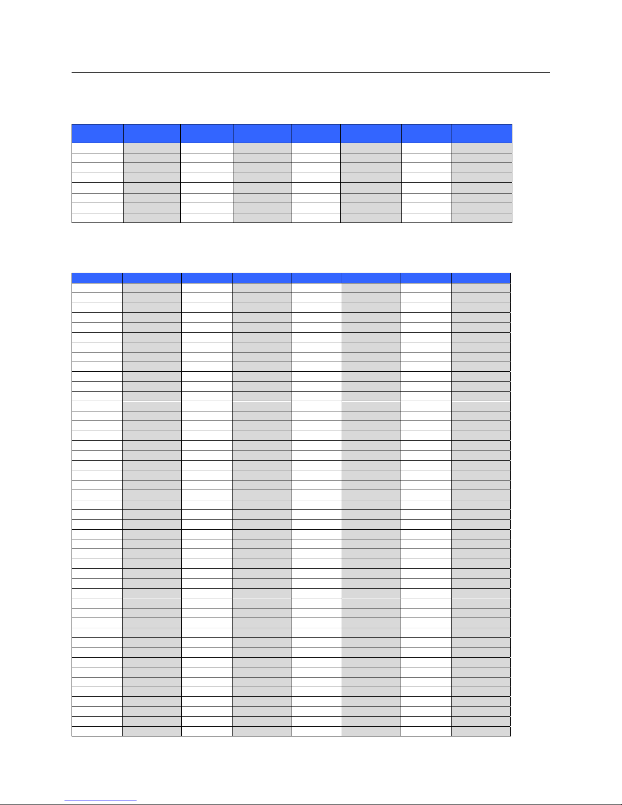
X12+2500 Channel Assignments
CH# MHz CH# MHz CH# MHz CH# MHz
00 2400.96 40 2421.44 80 2441.92 C0 2462.4
01 2401.28 41 2421.76 81 2442.24 C1 2462.72
02 2401.6 42 2422.08 82 2442.56 C2 2463.04
03 2401.92 43 2422.4 83 2442.88 C3 2463.36
04 2402.24 44 2422.72 84 2443.2 C4 2463.68
05 2402.56 45 2423.04 85 2443.52 C5 2464
06 2402.88 46 2423.36 86 2443.84 C6 2464.32
07 2403.2 47 2423.68 87 2444.16 C7 2464.64
08 2403.52 48 2424 88 2444.48 C8 2464.96
09 2403.84 49 2424.32 89 2444.8 C9 2465.28
0A 2404.16 4A 2424.64 8A 2445.12 CA 2465.6
0B 2404.48 4B 2424.96 8B 2445.44 CB 2465.92
0C 2404.8 4C 2425.28 8C 2445.76 CC 2466.24
0D 2405.12 4D 2425.6 8D 2446.08 CD 2466.56
0E 2405.44 4E 2425.92 8E 2446.4 CE 2466.88
0F 2405.76 4F 2426.24 8F 2446.72 CF 2467.2
10 2406.08 50 2426.56 90 2447.04 D0 2467.52
11 2406.4 51 2426.88 91 2447.36 D1 2467.84
12 2406.72 52 2427.2 92 2447.68 D2 2468.16
13 2407.04 53 2427.52 93 2448 D3 2468.48
14 2407.36 54 2427.84 94 2448.32 D4 2468.8
15 2407.68 55 2428.16 95 2448.64 D5 2469.12
16 2408 56 2428.48 96 2448.96 D6 2469.44
17 2408.32 57 2428.8 97 2449.28 D7 2469.76
18 2408.64 58 2429.12 98 2449.6 D8 2470.08
19 2408.96 59 2429.44 99 2449.92 D9 2470.4
1A 2409.28 5A 2429.76 9A 2450.24 DA 2470.72
1B 2409.6 5B 2430.08 9B 2450.56 DB 2471.04
1C 2409.92 5C 2430.4 9C 2450.88 DC 2471.36
1D 2410.24 5D 2430.72 9D 2451.2 DD 2471.68
1E 2410.56 5E 2431.04 9E 2451.52 DE 2472
1F 2410.88 5F 2431.36 9F 2451.84 DF 2472.32
20 2411.2 60 2431.68 A0 2452.16 E0 2472.64
21 2411.52 61 2432 A1 2452.48 E1 2472.96
22 2411.84 62 2432.32 A2 2452.8 E2 2473.28
23 2412.16 63 2432.64 A3 2453.12 E3 2473.6
24 2412.48 64 2432.96 A4 2453.44 E4 2473.92
25 2412.8 65 2433.28 A5 2453.76 E5 2474.24
26 2413.12 66 2433.6 A6 2454.08 E6 2474.56
27 2413.44 67 2433.92 A7 2454.4 E7 2474.88
28 2413.76 68 2434.24 A8 2454.72 E8 2475.2
29 2414.08 69 2434.56 A9 2455.04 E9 2475.52
2A 2414.4 6A 2434.88 AA 2455.36 EA 2475.84
2B 2414.72 6B 2435.2 AB 2455.68 EB 2476.16
2C 2415.04 6C 2435.52 AC 2456 EC 2476.48
2D 2415.36 6D 2435.84 AD 2456.32 ED 2476.8
TV3
MHz
CH#
TV38
MHz
CH#
TV39
MHz
CH#
APPENDIX B
TV40
MHz
22
Page 43

CH# MHz CH# MHz CH# MHz CH# MHz
2E 2415.68 6E 2436.16 AE 2456.64 EE 2477.12
2F 2416 6F 2436.48 AF 2456.96 EF 2477.44
30 2416.32 70 2436.8 B0 2457.28 F0 2477.76
31 2416.64 71 2437.12 B1 2457.6 F1 2478.08
32 2416.96 72 2437.44 B2 2457.92 F2 2478.4
33 2417.28 73 2437.76 B3 2458.24 F3 2478.72
34 2417.6 74 2438.08 B4 2458.56 F4 2479.04
35 2417.92 75 2438.4 B5 2458.88 F5 2479.36
36 2418.24 76 2438.72 B6 2459.2 F6 2479.68
37 2418.56 77 2439.04 B7 2459.52 F7 2480
38 2418.88 78 2439.36 B8 2459.84 F8 2480.32
39 2419.2 79 2439.68 B9 2460.16 F9 2480.64
3A 2419.52 7A 2440 BA 2460.48 FA 2480.96
3B 2419.84 7B 2440.32 BB 2460.8 FB 2481.28
3C 2420.16 7C 2440.64 BC 2461.12 FC 2481.6
3D 2420.48 7D 2440.96 BD 2461.44 FD 2481.92
3E 2420.8 7E 2441.28 BE 2461.76 FE 2482.24
3F 2421.12 7F 2441.6 BF 2462.08 FF 2482.56
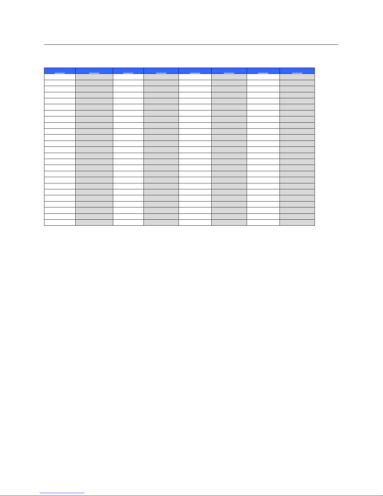
X12+915 Channel Assignments
CH# MHz CH# MHz CH# MHz CH# MHz
00 904.76 40 909.88 80 915 C0 920.12
01 904.84 41 909.96 81 915.08 C1 920.2
02 904.92 42 910.04 82 915.16 C2 920.28
03 905 43 910.12 83 915.24 C3 920.36
04 905.08 44 910.2 84 915.32 C4 920.44
05 905.16 45 910.28 85 915.4 C5 920.52
06 905.24 46 910.36 86 915.48 C6 920.6
07 905.32 47 910.44 87 915.56 C7 920.68
08 905.4 48 910.52 88 915.64 C8 920.76
09 905.48 49 910.6 89 915.72 C9 920.84
0A 905.56 4A 910.68 8A 915.8 CA 920.92
0B 905.64 4B 910.76 8B 915.88 CB 921
0C 905.72 4C 910.84 8C 915.96 CC 921.08
0D 905.8 4D 910.92 8D 916.04 CD 921.16
0E 905.88 4E 911 8E 916.12 CE 921.24
0F 905.96 4F 911.08 8F 916.2 CF 921.32
10 906.04 50 911.16 90 916.28 D0 921.4
11 906.12 51 911.24 91 916.36 D1 921.48
12 906.2 52 911.32 92 916.44 D2 921.56
13 906.28 53 911.4 93 916.52 D3 921.64
14 906.36 54 911.48 94 916.6 D4 921.72
15 906.44 55 911.56 95 916.68 D5 921.8
16 906.52 56 911.64 96 916.76 D6 921.88
17 906.6 57 911.72 97 916.84 D7 921.96
18 906.68 58 911.8 98 916.92 D8 922.04
19 906.76 59 911.88 99 917 D9 922.12
1A 906.84 5A 911.96 9A 917.08 DA 922.2
1B 906.92 5B 912.04 9B 917.16 DB 922.28
1C 907 5C 912.12 9C 917.24 DC 922.36
1D 907.08 5D 912.2 9D 917.32 DD 922.44
1E 907.16 5E 912.28 9E 917.4 DE 922.52
1F 907.24 5F 912.36 9F 917.48 DF 922.6
20 907.32 60 912.44 A0 917.56 E0 922.68
21 907.4 61 912.52 A1 917.64 E1 922.76
22 907.48 62 912.6 A2 917.72 E2 922.84
23 907.56 63 912.68 A3 917.8 E3 922.92
24 907.64 64 912.76 A4 917.88 E4 923
25 907.72 65 912.84 A5 917.96 E5 923.08
26 907.8 66 912.92 A6 918.04 E6 923.16
APPENDIX B
23
Page 44
CH# MHz CH# MHz CH# MHz CH# MHz
27 907.88 67 913 A7 918.12 E7 923.24
28 907.96 68 913.08 A8 918.2 E8 923.32
29 908.04 69 913.16 A9 918.28 E9 923.4
2A 908.12 6A 913.24 AA 918.36 EA 923.48
2B 908.2 6B 913.32 AB 918.44 EB 923.56
2C 908.28 6C 913.4 AC 918.52 EC 923.64
2D 908.36 6D 913.48 AD 918.6 ED 923.72
2E 908.44 6E 913.56 AE 918.68 EE 923.8
2F 908.52 6F 913.64 AF 918.76 EF 923.88
30 908.6 70 913.72 B0 918.84 F0 923.96
31 908.68 71 913.8 B1 918.92 F1 924.04
32 908.76 72 913.88 B2 919 F2 924.12
33 908.84 73 913.96 B3 919.08 F3 924.2
34 908.92 74 914.04 B4 919.16 F4 924.28
35 909 75 914.12 B5 919.24 F5 924.36
36 909.08 76 914.2 B6 919.32 F6 924.44
37 909.16 77 914.28 B7 919.4 F7 924.52
38 909.24 78 914.36 B8 919.48 F8 924.6
39 909.32 79 914.44 B9 919.56 F9 924.68
3A 909.4 7A 914.52 BA 919.64 FA 924.76
3B 909.48 7B 914.6 BB 919.72 FB 924.84
3C 909.56 7C 914.68 BC 919.8 FC 924.92
3D 909.64 7D 914.76 BD 919.88 FD 925
3E 909.72 7E 914.84 BE 919.96 FE 925.08
3F 909.8 7F 914.92 BF 920.04 FF 925.16
APPENDIX B
24
Page 45

TRANSLATIONS
APPENDIX C
Table of Translations
English Italian
ITALIANO
CH: CH: C: KAN: CH:
Menu Menu Menu Menu Menu
CALL CHIAMA LLAMAR RUF OPROEP
Off Off Off Aus Uit
POWER OFF? SPEGNERE? ¿APAGAR? AUSSCHALTEN? SPANNING UIT?
NO NO NO NEIN NEE
YES SI’ SI JA JA
LEAD CHECK DERIVAZIONI TEST ELECT ABL.TEST AFL. TEST
DISPLAY ECG MOSTRA ECG MOSTRAR ECG EKG-ANZEIGE TOON ECG
CONFIGURE CONFIGURA CONFIGURAR EINSTELLUNG CONFIGUREER
CHANNEL CANALE CANAL KANAL KANAAL
CABLE CAVO CABLE KABEL KABEL
4-Leadwire 4 Elettrodi 4 Electrodos 4-Elektroden 4 Electroden
5-Leadwire 5 Elettrodi 5 Electrodos 5-Elektroden 5 Electroden
10-Leadwire 10 Elettrodi 10 Electrodos 10-Elektroden 10 Electroden
VERSION VERSIONE VERSION VERSION VERSIE
BATTERY BATTERIA BATERIA BATTERIE BATTERIJ
Battery Voltage Livello Batteria Voltaje Bateria Batterie-Spannung Batterij spanning
DONE FINE OK FERTIG KLAAR
LANGUAGE LINGUA IDIOMA SPRACHE TAAL
Spanish
ESPAÑOL
German
DEUTSCH
Dutch
HOLLAND
25
Page 46

English French
FRANÇAIS
CH: CH: KAN: CANAL:
Menu Menu Menu Menu
CALL APPEL Dzwonek Chamar
Off Off Wyłącz Off
POWER OFF? ETEINDRE? Wyłączyć zasilanie? Desligar?
NO NON NIE NÃO
YES OUI TAK SIM
LEAD CHECK DÉRIVATIONS ELEKTRODY DERIVAÇÕES
DISPLAY ECG AFFICH. ECG EKG MOSTRAR ECG
CONFIGURE CONFIGURER USTAWIENIA CONFIGURAR
CHANNEL CANAL KANAŁ CANAL
CABLE CÀBLE KABEL CABO
4-Leadwire 4 Électrodes 4-ŻYŁOWY 4-eléctrodos
5-Leadwire 5 Électrodes 5-ŻYŁOWY 5-eléctrodos
10-Leadwire 10 Électrodes 10-ŻYŁOWY 10-eléctrodos
VERSION VERSION WERSJA VERSÃO
BATTERY BATTERIE BATERIA BATERIA
Battery Voltage Capacité Batt. Napięcie baterii Voltagem Bateria
DONE FIN GOTOWE OK
LANGUAGE LANGUAGE JĘZYK IDIOMA
Polish
POLSKI
Portuguese
PORTUGUES
APPENDIX C
26
 Loading...