

Mortara S12, S19 Service Manual

TABLE OF CONTENTS
1
REF 9516-183-50-ENG Rev M
S12/S19
SURVEYOR PATIENT MONITORS
SERVICE MANUAL
Manufactured by Mortara Instrument, Inc., Milwaukee, Wisconsin U.S.A.
CAUTION: Federal law restricts this device to sale by or on the order of a physician.

Copyright © 2018
by Mortara Instrument, Inc.
7865 N. 86th Street
Milwaukee, Wisconsin 53224
This document contains confidential information that belongs to Mortara Instrument, Inc. No part of this document
may be transmitted, reproduced, used, or disclosed outside of the receiving organization without the express written
consent of Mortara Instrument, Inc.
Mortara is a registered trademark of Mortara Instrument, Inc. Surveyor™, AM12M™, and VERITAS™ are
trademarks of Mortara Instrument, Inc.
Nellcor™, Covidien™, C-LOCK™, SatSeconds™, OxiMax™, MAX™, Max-Fast™, SoftCare™, Oxiband™, Dura-
Y™, PediCheck™, OxiCliq™, and Durasensor™ are trademarks of Nellcor Puritan Bennett Inc.
Smart Capnography™, Smart Breath Detection Algorithm™ (BDA™), Smart Alarm Respiratory Analysis ™
(SARA), Integrated Pulmonary Index™ (IPI), Microstream®, Filterline® and Capnoline® are trademarks or
registered trademarks of Oridion Medical Ltd.
Edwards® is a registered trademark of Edwards Lifesciences Corporation.
Oridion CO2 License Information -- NO IMPLIED LICENSE – Possession or purchase of this bedside monitor
does not convey any express or implied license to use the bedside monitor with unauthorized consumable CO2
sampling products which would, alone, or in combination with this bedside monitor, fall within the scope of one or
more patents relating to this bedside monitor and/or CO2 sampling consumable products.
The capnography component of this product is covered by one or more of the following US patents: 6,428,483;
6,997,880; 6,437,316; 7,488,229; 7,726,954 and their foreign equivalents. Additional patent applications pending.
All other trademarks and registered trademarks are the property of their respective owners.
For patent information, please visit www.welchallyn.com/patents

i
TABLE OF CONTENTS
1. GENERAL STATEMENTS
........................................................................................................................... 1
TECHNICAL SUPPORT AND SERVICE ................................................................................................................................ 1
2. NOTICES
.................................................................................................................................................... 2
M
ANUFACTURER’S RESPONSIBILITY
..................................................................................................................... 2
R
ESPONSIBILITY OF THE CUSTOMER
................................................................................................................... 2
E
QUIPMENT IDENTIFICATION
............................................................................................................................ 2
C
OPYRIGHT AND TRADEMARK NOTICES
............................................................................................................ 2
O
THER IMPORTANT INFORMATION
.................................................................................................................. 2
3. WARRANTY INFORMATION
.................................................................................................................... 3
Y
OUR MORTARA WARRANTY
............................................................................................................................. 3
4. USER SAFETY INFORMATION
.................................................................................................................. 5
S
AFETY REGULATIONS
......................................................................................................................................... 5
WARNINGS ............................................................................................................................................................... 5
POWER WARNINGS ..................................................................................................................................................... 6
ACCESSORIES, CABLES, AND EXTERNAL CONNECTIONS WARNINGS ......................................................................................... 8
USE WITH ELECTRO SURGERY DEVICES WARNINGS ............................................................................................................. 9
INSTALLATION AND MOUNTING WARNINGS ..................................................................................................................... 9
ECG WARNINGS ........................................................................................................................................................ 9
ECG CALCULATED HEART RATE WARNINGS .................................................................................................................. 10
WARNINGS FOR PATIENTS WITH PACEMAKERS ................................................................................................................ 11
RESPIRATION WARNINGS............................................................................................................................................ 11
SPO2 WARNINGS ..................................................................................................................................................... 11
NIBP WARNINGS ..................................................................................................................................................... 13
INVASIVE PRESSURE WARNINGS ................................................................................................................................... 14
CO2 WARNINGS ...................................................................................................................................................... 14
CARDIAC OUTPUT WARNINGS ..................................................................................................................................... 14
CAUTIONS ............................................................................................................................................................... 16
N
OTES
................................................................................................................................................................. 17
5. EQUIPMENT SYMBOLS AND MARKINGS
............................................................................................ 19
S
YMBOL DELINEATION
....................................................................................................................................... 19
6. ELECTROMAGNETIC COMPATABILITY (EMC)
................................................................................... 21
TABLE X-1 GUIDANCE AND MANUFACTURER’S DECLARATION: ELECTROMAGNETIC EMISSIONS .................................................. 22
TABLE X-2 GUIDANCE AND MANUFACTURER’S DECLARATION: ELECTROMAGNETIC IMMUNITY .................................................. 22
TABLE X-3 GUIDANCE AND MANUFACTURER’S DECLARATION: ELECTROMAGNETIC IMMUNITY .................................................. 23
TABLE X-4 RECOMMENDED SEPARATION DISTANCES BETWEEN PORTABLE AND MOBILE RF COMMUNICATIONS EQUIPMENT AND THE
EQUIPMENT ............................................................................................................................................................ 24
7. GENERAL CARE AND MAINTENANCE
................................................................................................ 25
P
RECAUTIONS
.................................................................................................................................................... 25
I
NSPECTION
........................................................................................................................................................ 25
C
LEANING
............................................................................................................................................................ 25
M
AINTENANCE
................................................................................................................................................... 28
B
ATTERY REPLACEMENT
.................................................................................................................................... 33
BATTERY LIFE AND CHARGE TIME ................................................................................................................................. 33

TABLE OF CONTENTS
ii
BATTERY CONDITIONS ................................................................................................................................................ 34
D
ECOMMISSIONING AND DISPOSAL
................................................................................................................... 34
C
ALIBRATION
...................................................................................................................................................... 34
CO2 CALIBRATION .................................................................................................................................................... 34
INVASIVE PRESSURE CALIBRATION ................................................................................................................................. 35
NIBP CALIBRATION ................................................................................................................................................... 35
S12/S19 P
REVENTATIVE MAINTENANCE RECORD
.......................................................................................... 36
8. DEVICE SETUP
......................................................................................................................................... 38
O
VERVIEW
.......................................................................................................................................................... 38
P
ATIENT INFORMATION
................................................................................................................................... 38
P
ARAMETERS
...................................................................................................................................................... 38
W
AVEFORMS
...................................................................................................................................................... 39
R
ECORDER
........................................................................................................................................................... 41
A
RRHYTHMIA
..................................................................................................................................................... 42
A
LARM SUSPEND
................................................................................................................................................ 43
A
LARMS
............................................................................................................................................................... 43
A
UDIO
................................................................................................................................................................. 45
R
ESTORE DEPARTMENTAL DEFAULTS
............................................................................................................... 46
A
DMINISTRATION
.............................................................................................................................................. 46
CONFIGURATION ...................................................................................................................................................... 47
COMMUNICATIONS ................................................................................................................................................... 47
SCREEN CLEANING .................................................................................................................................................... 48
ADMINISTRATION SETUP ALARMS DIALOGUE .................................................................................................................. 48
ADMINISTRATION SETUP SYSTEM DIALOGUE................................................................................................................... 50
ADMINISTRATION SETUP SERVICE DIALOGUE .................................................................................................................. 51
ADMINISTRATION SETUP FACTORY DIALOGUE ................................................................................................................. 51
9. UNIT DISSASSEMBLY
............................................................................................................................. 52
B
ATTERY REMOVAL & REPLACEMENT
............................................................................................................. 55
R
EAR HOUSING REMOVAL & REPLACEMENT
.................................................................................................. 56
P
ROCESSOR BOARD REMOVAL & REPLACEMENT
........................................................................................... 59
M
AIN BOARD REMOVAL & REPLACEMENT
..................................................................................................... 60
LCD R
EMOVAL & REPLACEMENT
S12
................................................................................................................ 62
LCD R
EMOVAL & REPLACEMENT
S19
................................................................................................................ 63
R
EMOVAL AND REPLACEMENT OF THE OPTIONAL THERMAL WRITER
(S12 ONLY)
.................................. 65
O
PTIONAL THERMAL WRITER FOR THE
S19
...................................................................................................... 68
10.
CONFORMANCE TESTING
................................................................................................................. 79
REQUIRED EQUIPMENT: ............................................................................................................................................. 79
1.0 POWER TESTING .......................................................................................................................................... 80
2.0 FUNCTIONAL TESTING ................................................................................................................................... 80
3.0 DEVICE CLEANING ...................................................................................................................................... 108
4.0 SAFETY TESTING......................................................................................................................................... 109
11.
PRODUCT SPECIFICATIONS
.............................................................................................................. 113
G
ENERAL SPECIFICATIONS
............................................................................................................................... 113
E
NVIRONMENTAL CONDITIONS
...................................................................................................................... 113
P
OWER REQUIREMENTS & BATTERY
.............................................................................................................. 114
D
ISPLAY SPECIFICATIONS
............................................................................................................................... 114
R
ECORDER SPECIFICATIONS
............................................................................................................................ 114
M
OUNTING SPECIFICATIONS
......................................................................................................................... 115
T
RENDING
......................................................................................................................................................... 115

TABLE OF CONTENTS
iii
12.
PARAMETER SPECIFICATIONS
.......................................................................................................... 116
P
ATIENT POPULATION
.................................................................................................................................... 116
W
AVEFORMS
.................................................................................................................................................... 116
ECG
.................................................................................................................................................................... 116
A
RRHYTHMIA ANALYSIS
.................................................................................................................................. 117
ST A
NALYSIS
..................................................................................................................................................... 118
NON-I
NVASIVE BLOOD PRESSURE
(NIBP)
...................................................................................................... 119
P
ULSE OXIMETRY (SP
O2)
................................................................................................................................ 119
T
EMPERATURE
.................................................................................................................................................. 120
R
ESPIRATIONS: VIA
ECG I
MPEDANCE
............................................................................................................ 120
C
APNOGRAPHY
(CO2)
....................................................................................................................................... 120
I
NVASIVE PRESSURES
........................................................................................................................................ 121
C
ARDIAC OUTPUT
............................................................................................................................................ 122
13.
PARAMETER ALARM LIMIT RANGES
............................................................................................. 124
A
DULT PATIENT MODE
................................................................................................................................... 124
P
EDIATRIC PATIENT MODE
............................................................................................................................. 126
14.
ALARM SPECIFICATIONS
................................................................................................................. 128
G
ENERAL ALARMS
........................................................................................................................................... 128
ECG
AND HR MESSAGES
................................................................................................................................. 128
NON-I
NVASIVE BLOOD PRESSURE
(NIBP) M
ESSAGES
................................................................................... 129
P
ULSE OXIMETRY (SP
O2) M
ESSAGES
............................................................................................................. 131
T
EMPERATURE MESSAGES
............................................................................................................................... 132
R
ESPIRATION MESSAGES
.................................................................................................................................. 133
C
APNOGRAPHY
(CO2) M
ESSAGES
.................................................................................................................. 134
I
NVASIVE PRESSURE MESSAGES
....................................................................................................................... 135
C
ARDIAC OUTPUT MESSAGES
.......................................................................................................................... 136
NETWORK MESSAGES ............................................................................................................................................. 136
15.
TROUBLESHOOTING
....................................................................................................................... 137
P
OWER AND BATTERY
..................................................................................................................................... 137
D
ISPLAY AND TOUCH SCREEN
......................................................................................................................... 137
ECG, A
RRHYTHMIA, AND
ST
........................................................................................................................... 138
NON-I
NVASIVE BLOOD PRESSURE
(NIBP)
...................................................................................................... 138
P
ULSE OXIMETRY (SP
O2)
................................................................................................................................ 139
T
EMPERATURE
.................................................................................................................................................. 139
R
ESPIRATIONS: VIA
ECG T
HORACIC IMPEDANCE
......................................................................................... 139
C
APNOGRAPHY
(CO2)
....................................................................................................................................... 139
I
NVASIVE PRESSURES
........................................................................................................................................ 140
C
ARDIAC OUTPUT
............................................................................................................................................ 140
16.
MOUNTING ACCESSORIES
.............................................................................................................. 144
Q
UICK DISCONNECT
(M-S
ERIES) WALL MOUNTING COMPONENTS
.............................................................. 144
V
ALUE (VESA
M-S
ERIES) WALL MOUNTING COMPONENTS
........................................................................... 144
P
REMIUM
(VHM-25) W
ALL MOUNT COMPONENTS
.................................................................................... 145
S
URVEYOR
S12 R
OLL STAND COMPONENTS (NOT TO BE USED WITH
S19)
.................................................... 146

TABLE OF CONTENTS
iv

1
1. GENERAL STATEMENTS
Technical Support and Service
Headquarters
Mortara Instrument, Inc.
7865 North 86th Street
Milwaukee, WI 53224
U.S.A.
Tel: 414.354.1600
Tel: 800.231.7437
Fax: 414.354.4760
Internet: http://www.mortara.com
European Union
Representative
Via Cimarosa, 103/105
40033 Casalecchio di Reno (Bologna)
Italy
Tel: +39 051 2987811
Fax: +39 051 6133582
E-mail: clienti.mortarait @ welchallyn.com
Service/Technical
Support Group
Mortara Instrument, Inc.
7865 North 86th Street
Milwaukee, WI 53224
U.S.A.
Tel: 414.354.1600
Service: 888.MORTARA
(888.667.8272)(USA)
Fax: 414.354.4760
E-mail: techsupport@mortara.com
24-hour Technical Support
Same-day Shipment of Replacement Parts
Biomedical Training Classes
Extended Warranties/Service Contracts
Sales Support/
Supplies & Accessories
Mortara Instrument, Inc.
7865 North 86th
Street Milwaukee, WI
53224
U.S.A.
Tel: 414.354.1600
Fax: 414.354.4760
E-mail: sales@mortara.com
Hospital Customers: orders.us@mortara.com
Physician Practice:orderspc.us@mortara.com
U.S. Distribution: orderspc.us@mortara.com
Mortara Instrument Germany
Hofgartenstraße 16
72379 Hechingen
Germany
Tel.: +49 (0) 7471 98 41 14-0
Fax: +49 (0) 7471 98 41 14-90
E-Mail: info @ welchallyn.com
Mortara Instrument Netherlands
“Amerika” Gebouw– 7e verdieping
Hoogoorddreef 15
1101 BA Amsterdam
Netherlands
Tel.: 020 206 1360
E-mail: infonl @ welchallyn.com
Mortara Instrument Australia
Head Office
Suite 4.01, 2-4 Lyonpark Road
Macquarie Park, Sydney
NSW 2113 Australia
Tel: 1800 650 083
Fax: +61 2 9562 0982
Mortara Instrument UK
Clinitron House, Excelsior Road
Ashby de la Zouch
Leicester LE65 1JG
Tel: 0207 365 6780
Fax: 0207 365 9694

2
2. NOTICES
Manufacturer’s Responsibility
Mortara Instrument, Inc. is responsible for the effects on safety and performance of the patient monitor, as indicated
by the label, only if article 2 of 93/42/EEC directive is applied, in particular:
WARNING: System installation and assembly operations, extensions, readjustments, modifications or
repairs are carried out by personnel authorized by Mortara Instrument, Inc. only.
The patient monitor is used in accordance with the instructions for use.
The patient monitor is correctly maintained according to the standards authorized by Mortara Instrument, Inc.
using original spare parts.
The patient monitor is used with original accessories and supplies that are in compliance with the standard
specifications described in this manual.
The electrical installation of the relevant room complies with the requirements of appropriate regulations.
Responsibility of the Customer
The user of this patient monitor is responsible for ensuring the implementation of a satisfactory maintenance
schedule. Failure to do so may cause undue failure and possible health hazards. This manual must be kept in a safe
place to prevent its deterioration and/or alteration. The user and Mortara Instrument, Inc. authorized personnel must
have access to this manual at any time.
The user of this patient monitor must periodically check the accessories, their functionality and integrity.
Equipment Identification
Mortara Instrument, Inc. equipment is identified by a serial and reference number on the back of the patient monitor.
Care should be taken so that these numbers are not defaced.
Copyright and Trademark Notices
This document contains information that is protected by copyright. All rights are reserved. No part of this
document may be photocopied, reproduced, or translated into another language without prior written consent of
Mortara Instrument, Inc.
Other Important Information
The information in this document is subject to change without notice.
Mortara Instrument, Inc. makes no warranty of any kind with regard to this material including, but not limited to,
implied warranties of merchantability and fitness for a particular purpose. Mortara Instrument, Inc. assumes no
responsibility for any errors or omissions that may appear in this document. Mortara Instrument, Inc. makes no
commitment to update or to keep current the information contained in this document.

3
3. WARRANTY INFORMATION
Your Mortara Warranty
MORTARA INSTRUMENT, INC. (hereafter referred to as “Mortara”) warrants that components within Mortara
products (hereafter referred to as “Product/s”) will be free from defects in workmanship and materials for the number
of years specified on documentation accompanying the product, or previously agreed to by the purchaser and
Mortara, or if not otherwise noted, for a period of twelve (12) months from the date of shipment.
Consumable, disposable or single use products such as, but not limited to, PAPER or ELECTRODES are warranted
to be free from defects in workmanship and materials for a period of 90 days from the date of shipment or the date of
first use, whichever is sooner.
Reusable product such as, but not limited to, BATTERIES, BLOOD PRESSURE CUFFS, BLOOD PRESSURE
HOSES, TRANSDUCER CABLES, Y-CABLES, PATIENT CABLES, LEAD WIRES, MAGNETIC STORAGE
MEDIUMS, CARRY CASES or MOUNTS, are warranted to be free from defects in workmanship and materials for
a period of 90 days. This warranty does not apply to damage to the Product/s caused by any or all of the following
circumstances or conditions:
a) Freight damage;
b) Supplies, accessories and internal parts NOT approved by Mortara;
c) Misapplication, misuse, abuse, and/or failure to follow the Product/s instruction sheets and/or information
guides;
d) Accident;
e) A disaster affecting the Product/s;
f) Alterations and/or modifications to the Product/s not authorized by Mortara;
g) Other events outside of Mortara’s reasonable control or not arising under normal operating conditions.
THE REMEDY UNDER THIS WARRANTY IS LIMITED TO THE REPAIR OR REPLACEMENT WITHOUT
CHARGE FOR LABOR OR MATERIALS, OR ANY PRODUCT/S FOUND UPON EXAMINATION BY
MORTARA TO HAVE BEEN DEFECTIVE. This remedy shall be conditioned upon receipt of notice by Mortara
of any alleged defects promptly after discovery thereof within the warranty period. Mortara’s obligations under the
foregoing warranty will further be conditioned upon the assumption by the purchaser of the Product/s (i) of all carrier
charges with respect to any Product/s returned to Mortara’s principal place or any other place as specifically
designated by Mortara or an authorized distributor or representative of Mortara, and (ii) all risk of loss in transit. It
is expressly agreed that the liability of Mortara is limited and that Mortara does not function as an insurer. A
purchaser of a Product/s, by its acceptance and purchase thereof, acknowledges and agrees that Mortara is not liable
for loss, harm, or damage due directly or indirectly to an occurrence or consequence there from relating to the
Product/s. If Mortara should be found liable to anyone under any theory (except the expressed warranty set forth
herein) for loss, harm, or damage, the liability of Mortara shall be limited to the lesser of the actual loss, harm, or
damage, or the original purchase price of the Product/s when sold.

4
WARRANTY INFORMATION
EXCEPT AS SET FORTH HEREIN WITH RESPECT TO REIMBURSEMENT OF LABOR CHARGES, A
PURCHASER’S SOLE EXCLUSIVE REMEDY AGAINST MORTARA FOR CLAIMS RELATING TO THE
PRODUCT/S FOR ANY AND ALL LOSSES AND DAMAGES RESULTING FROM ANY CAUSE SHALL BE
THE REPAIR OR REPLACEMENT OF DEFECTIVE PRODUCT/S TO THE EXTENT THAT THE DEFECT IS
NOTICED A N D M O R T A R A IS NOTIFIED WITHIN THE WARRANTY PERIOD. IN NO EVENT,
INCLUDING THE CLAIM FOR NEGLIGENCE, SHALL MORTARA BE LIABLE FOR INCIDENTAL,
SPECIAL, OR CONSEQUENTIAL DAMAGES, OR FOR ANY OTHER LOSS, DAMAGE, OR EXPENSE OF
ANY KIND, INCLUDING LOSS OF PROFITS, WHETHER UNDER TORT, NEGLIGENCE OR STRICT
LIABILITY THEORIES OF LAW, OR OTHERWISE. THIS WARRANTY IS EXPRESSLY IN LIEU OF ANY
OTHER WARRANTIES, EXPRESS OR IMPLIED, INCLUDING, BUT NOT LIMITED TO THE IMPLIED
WARRANTY OF MERCHANTABILITY AND THE WARRANTY OF FITNESS FOR A PARTICULAR
PURPOSE.
5
4. USER SAFETY INFORMATION
Warning: Means there is the possibility of personal injury to you or others.
Caution: Means there is the possibility of damage to the patient monitor.
Note: Provides information to further assist in the use of the patient monitor.
NOTE: This manual may contain screen shots and pictures. Any screen shots and pictures are provided
for reference only and are not intended to convey actual operating techniques. Consult the actual screen
in the host language for specific wording.
Safety Regulations
Surveyor is a medical patient monitor.
Surveyor and its accessories are labeled, according to European directive 93/42/EEC (MDD), as a class
IIb patient monitor, and class I medical patient monitors respectively.
Surveyor with all accessories that have a physical or logical connection with it, forms part of a Medical
Electrical System. Surveyor complies with various safety and performance regulations as mentioned in this
manual (Applied Standards).
Warnings
This manual gives important information about the use and safety of this patient monitor. Deviating from
operating procedures, misuse or misapplication of the patient monitor, or ignoring specifications and
recommendations could result in increased risk of harm to users, patients and bystanders, or damage to the
patient monitor.
Users are expected to be licensed clinical professionals knowledgeable about medical procedures and patient
care, and adequately trained in the use of this patient monitor. Patient monitor captures and presents data
reflecting a patient’s physiological condition that when reviewed by a trained physician or clinician can be
useful in determining a diagnosis; however, the data should not be used as a sole means for deter mining a
patient’s diagnosis.
Before attempting to use this device for clinical applications, the operator must read and understand the contents
of the user manual and other accompanying documents. Inadequate knowledge or training could result in
increased risk of harm to users, patients and bystanders, or damage to the patient monitor. Contact Mortara
Technical Service for additional training options.
The patient monitor provides the possibility to monitor multiple functions, but is not intended to be connected to
more than one patient.
Operation of the equipment beyond its specified ranges, or beyond normal physiological conditions of human
subjects, may cause inaccurate results.
To ensure the safety of both the patient and the device, 1.5 meters (5’) of open area should surround the patient.

USER SAFETY INFORMATION
6
A possible explosion hazard exists. Do not use the device in the presence of a flammable anesthetic mixture.
Do not mount any part of the device closer than 25 cm from outlets of flammable gases, including oxygen.
For proper operation and the safety of users or patients and bystanders, equipment and accessories must be
connected only as described in this manual.
Repairs and modification must be made by authorized and trained technical personnel. Unauthorized
modifications and repairs will void the Surveyor warranty and may pose a danger to patients and users.
If additional devices beyond Surveyor are connected to the patient, leakage currents through the patient might
add up and should be accounted for.
The Surveyor, as all medical equipment or systems, needs special precautions regarding EMC and needs to be
installed and put into service according to the EMC information provided in the installation procedure in order
to obtain a sufficient degree of immunity as well as not to create disturbance to other equipment. Refer to the
specific EMC instructions in this manual.
The quality of the signal produced by the device may be adversely affected by the use of other medical
equipment, including but not limited to electrosurgery and ultrasound machines. Do not use the system in the
presence of imaging equipment such as magnetic resonance imaging (MRI) and tomography systems.
Simultaneous operation may damage the device or lead to erroneous results.
Portable and mobile RF communications equipment may affect medical electrical equipment or systems as
well as the Surveyor and its accessories. Do not operate the Surveyor near high frequency emissions (e.g.
microwaves).
Various alarm conditions require operator to adjust alarm configurations individualized according to patient
condition and demographics. Surveyor supports the selection of appropriate alarm profiles when a patient is
admitted. The operator should check these settings with each patient admission to ensure the alarm settings are
appropriate for the individual patient. Inappropriate alarm configuration settings may render the alarm system
useless.
Surveyor alarms can only be silenced and not reset. This means that visual representation of an alarm condition
remains present after an operator-silenced action until the alarm condition disappears (unless obscured by
another, higher level, alarm). The auditory alarm signal does not re-activate after a silence action if the alarm
condition remains the same. As soon as the alarm condition of a silenced alarm goes away, the alarm can be
reactivated. Always respond promptly to alarms.
A patient monitor is an addition to monitoring patient status and is not intended to replace clinical assessments
and clinical judgments. It is important that a qualified individual regularly supervise the patient.
In an environment where multiple systems, whether Surveyor and/or other systems, are utilized for monitoring
patients, use of different alarm presets on each system may pose a safety risk. Be careful in using different
alarm conditions on different systems.
Power Warnings
Only use the Mortara-provided external power adapter with the Surveyor. Ensure that the power adapter is
connected to a properly grounded power terminal and the electrical installation complies with local safety
requirements for the environment where it is used.
To ensure that electrical safety is maintained during operation from AC power, the Surveyor external power
adapter must be plugged into a hospital-grade outlet.
Where the integrity of external protective earth conductor arrangement is in doubt, the device shall be operated
from its internal battery power source.
Do not use the Surveyor power supply to power other devices, because of the risk of additional leakage currents

USER SAFETY INFORMATION
7
and of transformer overload.
The device is not operative if no image appears on the screen. If the device become s inoperative during
monitoring, a medium level type alarm sounds and the system resets automatically.
Regularly check all mains power cables for damage and proper connection. Do not use equipment with a
damaged power cord.
The Surveyor contains a lithium ion battery. The following precautions should be taken regarding the battery:
o
Do not immerse the device in water.
o
Do not heat or throw the device in fire.
o
Do not leave the in conditions over 60 ºC or in a heated car.
o
Do not attempt to crush or drop the device.
o
Only use the approved Mortara battery pack with the Surveyor monitor.
o
Follow the instructions in the disposal section of this manual when the Surveyor monitor is taken out of
service.
The Surveyor battery must be initially fully charged prior to use. Ideally, the battery must be fully charged and
fully discharged several times to allow for optimal performance.
The Surveyor produces audible startup tones when powered on (two tones followed by two higher beeps). If a
patient monitor does not sound the startup tones when it is powered on, remove the patient monitor from service
and contact Mortara Technical Support.
If the AC power supply is interrupted or disconnected during monitoring, the Surveyor switches to battery
backup if the battery is properly installed and has sufficient charge. If power is completely interrupted,
including exhausting the battery supply, monitoring will cease until AC power supply has been restored or a
fresh battery is installed, and the monitor’s power switch is recycled.
For continued operation, always connect the Surveyor to a wall outlet when a Low Battery alarm indication
occurs. Failure to do this can lead to an interruption of monitoring.
Ensure the battery has sufficient charge prior to disconnecting the external power supply. To disconnect from
the AC power, disconnect the external power adapter from AC power first, then disconnect the power
connection from the back of the monitor.
Always reconnect the power cord to AC power after operating the patient monitor using battery power. This
ensures that the batteries are recharged for the next time the patient monitor is operated on battery power. A
light next to the on/off switch will illuminate indicating that the patient monitor is connected to mains power and
charging. The battery icon on the main display indicates when the battery is fully charged.

USER SAFETY INFORMATION
8
Accessories, Cables, and External Connections Warnings
The patient monitor is designed to meet applicable specifications when using Mortara-approved patient cables
and accessories. Use of non-approved cables and accessories may result in reduced performance and may pose
possible patient and user safety concerns.
It is the user’s responsibility to use only approved supplies, accessories and internal parts available through
Mortara Instrument, Inc. Product performance and patient safety require the use of supplies, accessories and
internal parts that comply with applicable standards. To maintain designed operator and patient safety,
peripheral equipment and accessories used that can come in direct patient contact must be in compliance with
applicable standards including IEC 60601-1, or other IEC standards (e.g., IEC 60950) as appropriate to the
patient monitor. Additionally, cables and accessories must comply with all EMC regulations. In Europe, cables
and accessories should bear the CE Mark. Only use parts and accessories supplied with the patient monitor and
available through Mortara Instrument, Inc.
Connected devices must stay outside of the patient environment, and must be electrically insulated from the
Surveyor by a separation device, or alternatively a permanent additional safety ground must be attached to the
Surveyor using the appropriate terminal at the back of the unit. Connecting additional devices to the patient
monitor may increase chassis and/or patient leakage currents. To maintain operator and patient safety,
consideration should be given to the requirements of IEC 60601-1-1, and leakage currents should be measured
to confirm no electric shock hazard exists.
Do not use excessive force on any of the connection cables and handle all accessories with care.
Proper clinical procedure must be employed to prep the electrode and sensor sites and to monitor the patient for
excessive skin irritation, inflammation, or other adverse reactions. Electrodes and other sensors are intended for
short-term use and should be removed from the patient promptly following testing.
Conductive parts of the ECG patient cables, electrodes, and associated connections of type CF applied parts,
including the neutral conductor of the patient cable and electrode should not come into contact with other
conductive parts including earth ground.
To avoid the possibility of serious injury or death during patient defibrillation, do not come into contact with
patient monitor or patient cables. Additionally, proper placement of defibrillator paddles in relation to the ECG
electrodes is required to minimize harm to the patient.
To avoid potential for spread of disease or infection, single-use disposable components (e.g., electrodes, IBP
catheters, disposable SpO2 sensors, disposable temperature sensors, single-use blood pressure cuffs, etc.) must
not be reused.
Mortara-approved manufacturers of accessories provide separate user manuals (e.g., patient cables, electrodes,
etc.). Read these manuals thoroughly and refer to them for specific functions. It is recommended to keep all
manuals together.
To maintain safety and effectiveness, reusable sensors and cables - such as ECG electrodes and SpO2 sensors must not be used beyond their expiration date or useful life.
All accessories including hoses, cables, connectors, hoses and other patient-applied parts supplied with the
Surveyor do NOT contain any Latex. If the patient develops an allergic reaction or rashes, immediately remove
the accessory and inform Mortara Technical Support.
Check the date and integrity of the packing of all accessories that need to be sterilized before use.
Do not attach unauthorized devices such as a mouse or keyboard to the USB port.
Do not attach unauthorized patient cable for use with AM12M. Patient cable should provide locking mechanism
to mating device.

USER SAFETY INFORMATION
9
Use with Electro Surgery Devices Warnings
The Surveyor is approved for use in the presence of electrosurgical (ESU) equipment providing the following
precautions are taken:
o
To minimize the risk of patient burns, only use ESU equipment that monitors the impedance of the ESU
return wires.
o
Users should be properly trained in the operation of the ESU equipment.
o
The AM12M 12-Lead ECG Acquisition Module should NOT be used when operating ESU equipment.
o
Keep patient-applied cables (e.g., ECG lead wires) off of earth ground and away from the ESU knife and
return wires to prevent burns to measurement sites.
o
To prevent burns to the patient in the event of a defective neutral ECG electrode of the device, it is
necessary to place ECG electrodes far from the neutral electrode, and as equidistant as possible from the
blade-neutral axis of the surgical patient monitor.
o
When activating the ESU device, the ECG signals may be distorted or may disappear, and Lead Fail or
Noise alarms might be present. The signal should return once the ESU activation stops.
o
When activating the ESU device, using the SpO2 parameter as the heart rate source rather than the ECG
parameter to determine heart rate may be clinically preferred.
Installation and Mounting Warnings
Place the Surveyor on a flat and leveled surface or mount it according to the manufacturer’s instructions. Place
the Surveyor in a well-ventilated place. Keep the Surveyor away from overly hot, cold or humid places, places
directly under sunlight, or dusty surroundings.
Ensure that the Surveyor is securely placed or mounted such that it does not tip or drop which may damage the
monitor and potentially create a hazard to patients and hospital personnel.
Only approved rolling stands and wall-mount fixtures should be used with the Surveyor.
A VESA-standard adapter is available on the back of the Surveyor system for wall, swivel-arm or rolling-stand
mounting. The user is responsible for correct installation of the system.
Do not mount the S12 on a rolling stand at a height exceeding 110 cm (43”).
The S19 should NOT be mounted on a rolling stand.
ECG Warnings
Excessive patient movement could interfere with the operation of the system.
Proper patient preparation is important to proper application of ECG electrodes and operation of the patient
monitor.
If the ECG amplifier input is out of normal operating range, the display will indicate a lead fail for the lead(s)
where this condition is present and if the signal is being displayed or printed, the respective lead(s) will print out
as blank. A lead fail alarm is generated on the Surveyor Central monitoring station
The AM12M acquisition module automatically calibrates when it is connected to the monitor or when the
monitor powers up. If there is a very high amount of electrical interference present at that time (usually because
electrodes make spurious contact with earth ground), the calibration may fail. The monitor is aware of the failure
and will not display the ECG waveforms. If this happens, the user should attempt to recalibrate by reconnecting
the AM12M to the monitor, making sure that there are no spurious contacts between electrodes and earth
ground.
Patient cables intended for use with the patient monitor include series resistance (9 Kilo Ohm minimum) in each
lead for defibrillation protection. Patient cables should be checked for cracks or breakage prior to use.
ECG electrodes could cause skin irritation; patients should be examined for signs of irritation or inflammation.

USER SAFETY INFORMATION
10
Defibrillation protection is guaranteed when the original Mortara ECG patient cables are used.
The system captures and presents data reflecting a patient’s physiological condition that when reviewed by a
trained physician or clinician can be useful in determining a diagnosis. However, the data should not be used as
a sole means for determining a patient’s diagnosis. The system is equipped with Mortara’s VERITAS™ 12-lead
resting ECG interpretation algorithm. The VERITAS ECG algorithm can provide an over-reading physician
with a silent second opinion through diagnostic statements output on the ECG report.
12-lead ECGs acquired through Surveyor will normally use a modified lead system with the limb electrodes
positioned on the torso. Although this is a generally accepted practice (e.g., in stress testing), the different
electrode positions can cause morphology changes on the ECG, thus influencing their interpretation. Most
frequently seen differences are a vertical and rightward axis shift, minor changes of evidence of old inferior
infarction and changes in the T-wave in the limb leads. All 12-lead ECGs printed with Surveyor have a warning
message that alerts the physician that the ECG might have been acquired with torso positioned limb leads. It is
recommended that you place the electrodes as close as possible to the normal limb positions avoiding the
possibility of causing artifact. The right arm and left arm electrodes should be placed on the clavicles as close
as possible to the arms. The left leg electrode should be placed as close as possible to the left leg without
subjecting it to the possibility of motion artifact.
During periods of lead fail and when a reduced lead set is used for patient monitoring, 12-lead resting ECG
interpretation cannot be reliably used in determining a diagnosis.
For full diagnostic quality, the resting ECG should be printed on the Surveyor Central Station printer and not on
the S12 or S19 strip chart recorder.
ECG Calculated Heart Rate Warnings
Heart rate indication is usually not affected by pacemakers with direct cardiac application, ventricular or
supraventricular arrhythmias or irregular heart rates; however, in some conditions a pacemaker pulse can give
rise to double QRS detections. Also, not activating the “Analyze Pacers” field in the signals menu in the
presence of a pacemaker might lead to beat detections without a QRS complex due to the detection of the
pacemaker spike.
Heart rate is calculated over 16 beats at rates over 40 bpm and 4 beats at lower heart rates. This results in a
response time of 9 seconds or less when the hear t rate changes suddenly from 80 bpm to 40 or 120 bpm, as
measured according to ANSI/AAMI EC13 and IEC60601-2-27.
Tall and peaked T-waves may affect QRS detection resulting in doubled heart rates. Surveyor rejects tall
T-Waves less than or equal to 240% of a 1mV QRS in diagnostic mode, and 70% of a 1mV QRS in monitoring
mode, as well as a Q-T interval of 350 ms measured for both diagnostic and monitoring modes according to
ANSI/AAMI EC13 and IEC 60601-2-27.
The heart rate meter correctly detects all beats of the alternating beat type waveforms considered in
ANSI/AAMI EC 13 and IEC 60601-2-27 Figure 201.101 patterns A1-A4 if the QRS amplitudes exceed the
minimum detection threshold set by the user.
Time to tachycardia, as measured according to ANSI/AAMI EC13 and IEC 60601-2-27 Figure 201.101 patterns
B1-B2 is less than 8 seconds.
Heart rate indication is not reliable during episodes of ventricular fibrillation.
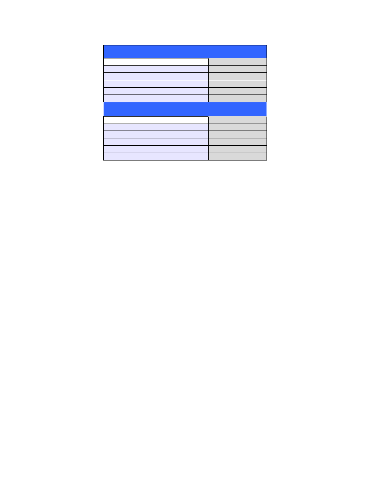
The summarized performance of the QRS recognition and classification algorithm on standard databases, as
defined by ANSI/AAMI EC 57, is as follows:
USER SAFETY INFORMATION
11
MIT Database
Performance Measures
Mortara
QRS Detection Sensitivity %
99.94
QRS Detection Positive Predictivity %
99.87
PVC Detection Sensitivity %
95.49
PVC Detection Positive Predictivity %
97.05
PVC Detection False Positive Rate %
0.220
AHA Database
Performance Measures
Mortara
QRS Detection Sensitivity %
99.86
QRS Detection Positive Predictivity %
99.90
PVC Detection Sensitivity %
93.49
PVC Detection Positive Predictivity %
98.32
PVC Detection False Positive Rate %
0.162
Because of noise, artifact and the many different physiological manifestations of the ECG signal, it is inevitable
that some beats are not detected or correctly classified by the system. The user is advised not to rely completely
on automatic alarm systems for the monitoring of critical patients.
Warnings for Patients with Pacemakers
Rate meters may continue to count the pacemaker rate during occurrences of cardiac arrest or some arrhythmias.
Do not rely entirely upon rate meter alarms. Keep pacemaker patients under close surveillance.
When using the 3/5 lead ECG cable, pacemaker spikes are normally recognized and rejected by the software.
Signals are recognized as pacemaker spikes when they have a slew rate over 1.4 V/s, as measured according to
the ANSI/AAMI EC 13 and IEC 60601-2-27 standards.
When using the AM12M 12-lead ECG Acquisition Module, pacemaker spikes in the range of 0.3 to 1.3 mS, +/2 to +/-700 mV are recognized and rejected according to the ANSI/AAMI EC13 and IEC 60601-227:2011standards.
The pacemaker rejection software can be deactivated by the user. This should not be done for patients with a
pacemaker or suspected to have a pacemaker implanted because this can lead to a heart rate indication and
failure to alarm for cardiac arrest.
Other than the influence on beat detection as stated above, there is no known safety hazard if other equipment,
such as pacemakers or other stimulators, is used simultaneously with the system.
Respiration Warnings
When using an ECG electrode to calculate respiration rate via the thorax impedance method, movement artifacts
may create inaccurate results. Respiration rates derived from CO2 parameter is not subject to such movement
artifacts.
SpO2 Warnings
Use only approved pulse oximetry sensors specifically intended for use with the patient monitor. Unapproved
components can result in degraded performance and/or device malfunction.
Use pulse oximetry sensors specified for the correct patient mode and for the correct application position.
Pulse oximetry sensors must be checked a minimum of every 4 hours and moved to a new site as necessary.
Reposition the sensor at least once every 24 hours to allow the patient’s skin to breathe.
Tissue damage or inaccurate measurements may be caused by incorrect SpO2 sensor application or use, such as

USER SAFETY INFORMATION
12
wrapping too tightly, applying supplemental tape, failing to inspect periodically, or failing to position
appropriately. Read the Instructions for Use provided with the SpO2 sensor carefully prior to use.
Do not sterilize or immerse pulse oximetry sensors in liquid. Clean and/or disinfect re-usable sensors between
patients.
Pulse oximetry sensors are susceptible to high ambient light interference including surgical lights, especially
xenon light sources, ambient photodynamic therapy (e.g., Bilirubin lamps), fluorescent lights, infrared heating
lamps, direct sunlight. Shield the sensor area as necessary.
SpO2 measurement may be adversely affected by dyes (e.g., methylene blue, indocyanine green, indigo,
carmine, fluorescein) introduced into the bloodstream
That factors that may cause inaccurate readings and alarms, decreased perfusion, and or low signal strength
include:
Interfering substances:
o
Carboxyhemoglobin may erroneously increase SpO2 reading.
o
Methemoglobin (MetHb) usually represents less than 1% of the total Hgb, but in the case of
methemoglobinemia that can be congenital or induced by some IV dyes, antibiotics (such as sulphas,)
inhaled gases etc. this level increases sharply and thus can confound the SpO2 reading.
o
Intravascular dyes (such as indocyanine green, methylene blue, etc.).
Physiological conditions:
o
Cardiac arrest
o Hypotension
o Shock
o
Severe vasoconstriction
o
Severe anemia
o
Hypothermia
o
Venous pulsations
o
Ventricular septal defects (VSDs)
Sensor placement:
o
Incorrect sensor placement
o
Poor sensor fit
Any condition that restricts blood flow such as the use of a blood pressure cuff or supplemental tape, or
extremes in systemic vascular resistance may cause inability to determine accurate SpO2 readings.
Certain conditions such as physical movement (patient and imposed motion); diagnostic testing; low perfusion;
electromagnetic interference; electrosurgical patient monitors; dysfunctional hemoglobin; and inappropriate
positioning of the pulse oximeter sensor may result in pulse oximetry readings that are unreliable.
SpO2 signal inadequacy is indicated by error messages or alarms generated at the Surveyor patient monitors.
If the accuracy of any measurement does not seem reasonable, first check the patient’s vital signs, and then
check for conditions that may cause inaccurate SpO2 readings. If the problem is still not resolved, check the
monitor and the SpO2 module, cable, or sensor for proper functioning.
A pulse oximeter is not an apnea monitor. A pulse oximeter should be considered an early warning device. As a
trend toward patient deoxygenation is indicated, blood samples should be analyzed by a laboratory CO-oximeter
to completely understand the patient’s condition. Check that the pulse oximetry waveform is physiological in
shape.
To prevent erroneous readings, do not use physically damaged sensors, cables or modules. Discard a damaged
sensor or cable immediately.
The performance of the pulse oximetry may be compromised by excessive motion including tremors or

USER SAFETY INFORMATION
13
shivering.
Nail polish and/or artificial fingernails can affect the accuracy of pulse oximetry and should be removed.
Pulse rate measurement is based on the optical detection of a peripheral flow pulse. While a pulse rate does
assist with the detection or absence of a peripheral pulse, the pulse oximeter should not be used as a replacement
or substitute for ECG-based arrhythmia analysis.
In certain situations such as low perfusion or weak signal strength, such as with patients who have pigmented or
thick skin, inaccurate SpO2 measurements may be reported. Verification of oxygenation should be made
through other means, particularly in preterm infants, and patients with chronic lung disease, prior to instituting
any therapy or intervention.
Always monitor ECG for ar rhythmia detection purposes. HR calculated from pulsatile SpO2 waveform may
differ significantly from ECG HR measured values.
NIBP Warnings
Use only approved blood pressure (BP) cuffs specifically intended for use with the Surveyor patient monitors.
Use the correct size cuff for the intended limb (see indication of cuff size in cm printed on cuff) of the patient.
The terminology printed on some BP cuffs like “child,” “adult,” “thigh,” etc., is only an indication of the size of
the cuff and should not be used to determine if the cuff is suitable for the limb. Use the range markers on the BP
cuff’s to determine whether a particular cuff fits the patient’s arm or not.
The Surveyor patient monitor is not intended for use with neonates.
Do not fold, clamp, cut, or alter the pressure hose of the cuff or the monitor.
Periodically check the limb connected to the cuff for adequate perfusion, circulation, and function. Repeated
NIBP measurements can lead to hematomas, limb ischemia, and other limb injuries. Kinked or blocked hoses
can lead to prolonged impairment of blood circulation and lead to injury.
Educate the patient to relax, rest, and lie still during inflation and pressure measurements. Patient movement can
lead to artifacts or errors.
The pressure measurement might be influenced by patient position, physical conditions, and other factors.
Avoid placing the blood pressure cuff on the arm next to where a patient has had a mastectomy.
Avoid applying the cuff to a wounded limb as this can cause further injury. Use with caution in patients with
dermatological disease, subcutaneous laceration, or other integumentary compromise as there may exist a skin
damage hazard during electronic NIBP measurements. Follow prudent evidence-based clinical practice to
determine if an electronic blood pressure is safe for these patients.
There may be an increased risk of hematomas in patients with serious coagulation problems.
Avoid applying the cuff to a limb with a catheter, arterio-venous shunt or infusion pump applied. The cuff
pressure could produce damage to the tissues surrounding the catheter, shunt or the infusion needle, or
compromise the infusion flow.
To avoid the potential for spread of disease or infection, reusable blood pressure cuffs should be cleaned after
each patient use. Disposable blood pressure cuffs should not be used with multiple patients.
Inflation of the NIBP cuff can cause a temporary degradation of monitoring of other parameters derived from
the same limb, including invasive pressure and SpO2 measurements. If applicable, place the SpO2 sensor and
the NIBP cuff on different limbs.

USER SAFETY INFORMATION
14
An irregular heart beat (arrhythmia) causes beat-to-beat blood pressure variations and may therefore disturb
the NIBP measurement, which may fail or be inaccurate. It is advisable to confirm automatic NIBP
measurements periodically for patients with frequent premature beats or a very irregular heart rate, for example
caused by atrial fibrillation.
NIBP measurements may be inaccurate or fail in the presence of excessive movement, shivering, or trembling.
Advise patients to relax and avoid moving when a blood pressure measurement is made.
NIBP cuffs and hoses supplied with the Surveyor do NOT contain any Latex. If the patient develops an allergic
reaction or rashes, immediately remove the cuff.
Invasive Pressure Warnings
All invasive procedures involve risks to the patient. Use aseptic technique. Follow catheter manufacturer's
instructions and established hospital guidelines.
Ensure that no part of the patient connections touches any electrically conductive material including earth.
Only use invasive pressures transducers that can withstand defibrillation as required by ANSI/AAMI BP22
standard.
Mechanical shock to the invasive blood pressure transducer may cause severe shifts in zero balance and
calibration, and cause erroneous readings.
CO2 Warnings
Always inspect the airway adapter for a tight connection and proper operation before attaching it to the patient.
Remove the airway sampling line from the patient’s airway while nebulized medications are being delivered.
Route all tubing away from the patient’s throat to avoid strangulation.
Do not apply pressurized air to any outlet or tubing connected to the monitor. Pressure may destroy sensitive
elements.
When monitoring an anesthetized patient in an operating room environment, it is recommended to connect the
CO2 exhaust port of the Surveyor to the hospital’s waste gas scavenging system so as to prevent exposure for
other patients and hospital personnel to the patient’s respiratory sample. Ensure that sampled gases are not
returned from the exhaust port to a breathing system such as a ventilator. Use standard clinical guidelines and/or
hospital procedures. Scavenge vacuum greater than 1mmHg may result in damage to the Surveyor.
When using a sampling line for intubated patients with a closed suction system, do not place the airway adapter
between the suction catheter and endotracheal tube. This is to ensure that the airway adapter does not interfere
with the functioning of the suction catheter.
Loose or damaged connections may compromise ventilation or cause an inaccurate measurement of respiratory
gases. Securely connect all components and check connections for leaks according to standard clinical
procedures.
Do not cut or remove any part of the sample line. Cutting the sample line could lead to erroneous readings.
If too much moisture enters the sampling line (i.e., from ambient humidity or breathing of unusually humid air),
the message CO2 Purging Line will appear in the message area. If the sampling line cannot be cleared, the
message CO2 occluded line will appear in the message area. Replace the sampling line once the CO2 occluded
line message appears.
Cardiac Output Warnings

USER SAFETY INFORMATION
15
Refer to the catheter package insert provided with each PA catheter for the appropriate computation constant,
specific instructions on catheter placement and use, warnings, cautions, and specifications.
Inaccurate Cardiac Output measurements may be caused by:
o
Incorrect placement or position of the catheter.
o
Excessive variation in pulmonary artery blood temperature, perhaps caused by bolus drug
administration.
o
Clot formation on the thermistor port.
o
Anatomical abnormalities, (for example, cardiac shunts).
o
Excessive patient movement.
o
Repeated intermittent flushes of cold fluid through the fluid lumens of the catheter.
o
Electrocautery or electrosurgical device interference.
o
Rapid changes in cardiac output.
o
Using an incorrect computation constant.

USER SAFETY INFORMATION
16
Cautions
Cleaning must be performed with the system turned off. Let all parts dry well before turning the power
back on.
Prevent liquids from penetrating the system, components, and transmitters. Do not spray the system with liquid
cleaning agents. If liquids have penetrated the system, open by authorized personnel for inspection and let dry
completely.
Do not attempt to clean the patient monitor or patient cables by submersing into a liquid, autoclaving, or steam
cleaning as this may damage equipment or reduce its usable life. Wipe the exterior surfaces with a warm water
and mild detergent solution and then dry with a clean cloth. Use of unspecified cleaning/disinfecting agents,
failure to follow recommended procedures, or contact with unspecified materials could result in increased risk of
harm to users, patients and bystanders, or damage to the patient monitor.
No user-serviceable parts inside. Screw removal by authorized service personnel only. Damaged or suspected
inoperative equipment must be immediately removed from use and must be checked/repaired by authorized
service personnel prior to continued use.
The rechargeable internal battery is a sealed lithium ion type. If the battery appears to become defective, refer
to Mortara Technical Support.
Do not pull or stretch patient cables as this could result in mechanical and/or electrical failures. When not in
use, patient cables can be stored. Keep patient cables should be stored off of the floor away from bedrails and
wheels to avoid cable damage. Roll the patient cables into a loose loop prior to hanging for storage.
When necessary, dispose of the patient monitor, its components and accessories (e.g., batteries, cables,
electrodes), and/or packing materials in accordance with local regulations.
Do not connect the patient monitor to any unauthorized patient monitors or use any third-party accessories. This
may cause inaccurate measurements or harm the patient. Installation and connection to data networks must be
performed by properly trained personnel, authorized by Mortara.
Check that all operating and environment conditions such as ambient temperature meet the specifications of the
Surveyor.
Do not exert excessive pressure on the touch panel LCD. Excessive pressure may permanently damage the
display.
During MRI scanning, the module must be placed outside the MRI suite. When the module is used outside the
MRI suite, EtCO2 monitoring can be implemented using the FilterLine XL.
Use of a CO2 sampling line with H in its name (indicating that it is for use in humidified environments) during
MRI scanning may cause interference. The use of non H sampling lines is advised.

USER SAFETY INFORMATION
17
Microstream® etCO2 sampling lines are designed for single patient use, and are not to be reprocessed. Do not
attempt to clean, disinfect, sterilize or flush any part of the sampling line as this can cause damage to the
monitor.
Dispose of sampling lines according to standard operating procedures or local regulations for the disposal of
contaminated medical waste.
Before use, carefully read the Microstream® etCO2 sampling lines Directions for Use.
Only use Microstream® etCO2 sampling lines to ensure the monitor functions properly.
Notes
The Surveyor’s NIBP parameter is indicated for use with pregnant patients, including those with pre-eclamptic
or eclamptic conditions.
Patient movements may generate excessive noise that may affect the quality of signals and derived parameters
and waveforms.
Proper patient preparation is important to proper application of sensors and electrodes to ensure the correct
operation of the patient monitor.
There is no known safety hazard if other equipment, such as pacemakers or other stimulators, is used
simultaneously with the patient monitor; however, disturbance to the signal may occur.
If an ECG electrode is not connected properly to the patient, or one or more of the patient cable lead wires are
damaged, the display will indicate a lead fault for the lead(s) where the condition is present and if the signal is
being printed, the respective lead(s) will print out as blank.
This patient monitor is intended to be used in a hospital or doctor’s office setting, and should be used and stored
according to the environmental conditions specified.
During nebulization or suction for intubated patients, in order to avoid moisture buildup and sampling line
occlusion, remove the sampling line luer connector from the monitor.
Replace the sampling line according to hospital protocol or when a blockage is indicated by the device.
Excessive patient secretions or a build‐up of liquids in the airway tubing may occlude the sampling line,
requiring more frequent replacement.
When the caution message “Blockage” appears on the screen, indicating that the FilterLine which is attached to
the monitor is blocked, the monitor’s CO2 pump will stop pumping the patient’s breath into the monitor for
testing. Follow the instructions that appear in the Troubleshooting section of this manual: First disconnect and
reconnect the FilterLine. If the message still appears, disconnect and replace the FilterLine. Once a working
FilterLine is attached to the monitor, the pump will automatically resume operation.
Following connection of the CO2 sampling line to the monitor and patient, check that CO2 values appear on the
monitor display.

USER SAFETY INFORMATION
18
The device is ETL listed:
ETL-Listed device in the USA and Canada.
Upon request, Mortara can supply a Service Manual that includes additional calibration and test instructions as
well as list of spare parts and accessories that must be used with the Surveyor patient monitors.
19
5. EQUIPMENT SYMBOLS AND MARKINGS
Symbol Delineation
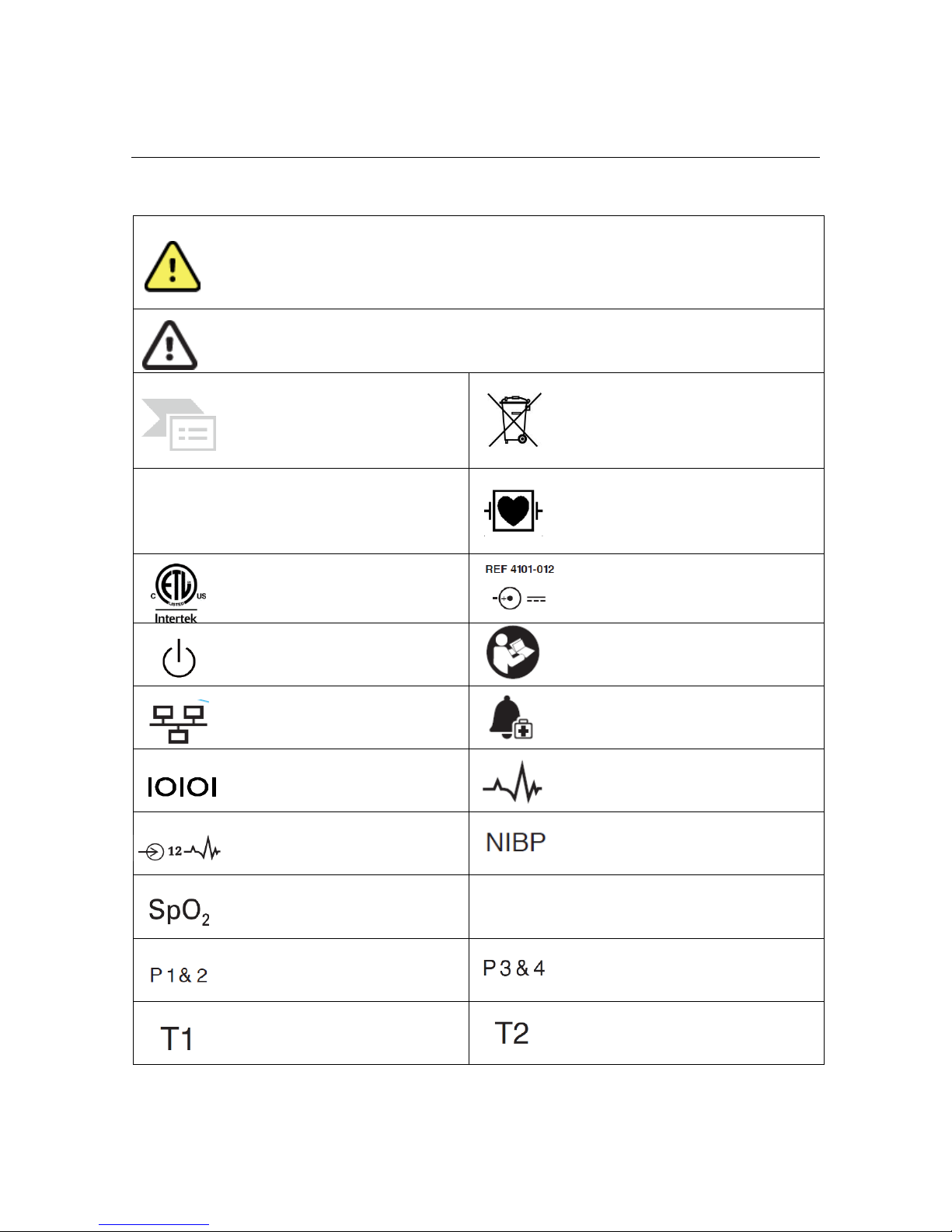
WARNING The warning statements in this manual identify conditions or practices
that could lead to illness, injury, or death. In addition, when used on a patient
applied part, this symbol indicates defibrillation protection is in the cables. Warning
symbols will appear with a grey background in a black and white document.
CAUTION The caution statements in this manual identify conditions or practices
that could result in damage to the equipment or other property, or loss of data.
Indicates compliance to applicable
European Union directives
Do not dispose as unsorted municipal
waste. Per European Union Directive
2002/96, requires separate handling for
waste disposal according to national
requirements
IPX1
Indicates device has been tested for
safety from vertically dripping water;
specifically, it indicates DRIP PROOF, a
higher than ordinary level of protection
from drips, leaks, and spills
Defibrillator-proof type CF applied part
Tested for safety by the Intertek
according to applicable U.S. and
Canadian standards and requirements
External power AC/DC power supply; use
only Mortara Power Supply; REF 4101-012
Power On/Off switch
Consult accompanying documents
Local Area Network interface
External alarm interface
Interface to external devices – Reserved
for future use
Connector for 3/5 lead ECG parameter
Connector for 12-lead ECG parameter
using Mortara AM12M
Connector for non-invasive blood pressure
parameter
Connector for oxygen saturation
parameter
CO
Connector for cardiac output parameter
Connector for invasive pressure 1 & 2
parameters
Connector for invasive pressure 3 & 4
parameters
Connector for temperature 1
parameter
Connector for temperature 2 parameter
EQUIPMENT SYMBOLS AND MARKINGS
20
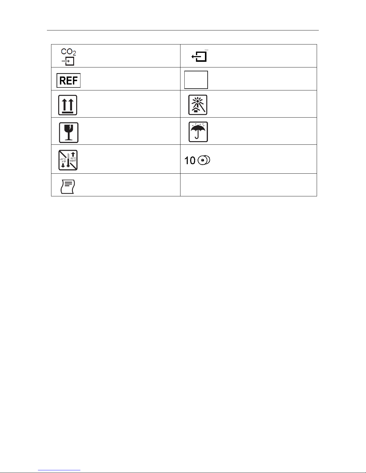
Connector for CO2 parameter
Connector for CO2 parameter exhaust port
Catalog number for relevant Mortara
part
Serial number
This end up
Keep away from sunlight
Fragile, handle with care
Keep dry
Storage temperature range
10 rolls of recorder paper per case
Recorder interface (S19 only)
SN

21
6. ELECTROMAGNETIC COMPATABILITY (EMC)
When using the patient monitor, assess the electromagnetic compatibility with surrounding devices.
An electronic device may either generate or receive electromagnetic interference. Testing for electromagnetic
compatibility (EMC) has been performed on the bedside monitor according to the international standard for EMC
for medical bedside monitors (IEC 60601-1-2). This IEC standard has been adopted in Europe as the European
Norm (EN 60601-1-2).
The patient monitor should not be used adjacent to or stacked with other equipment. If the patient monitor is
used in this manner, verify the patient monitor operates in an acc eptable manner in the configuration in which it
will be used.
Fixed, portable, and mobile radio frequency communications equipment may affect the performance of medical
equipment. See Table X-4 for recommended separation distances between the radio equipment and the patient
monitor.
The use of accessories, transducers, and cables other than those specified by Mortara Instrument may result in
increased emissions or decreased immunity of the equipment.

ELECTROMAGNETIC COMPATABILITY (EMC)
22
Table X-1 Guidance and Manufacturer’s Declaration: Electromagnetic Emissions
The equipment is intended for use in the electromagnetic environment specified in the table below. The customer or
the user of the equipment should ensure that it is used in such an environment.
Emissions Test
Compliance
Electromagnetic Environment: Guidance
RF Emissions
CISPR 11
Group 1
The Surveyor patient monitor uses RF energy only for its internal
function. Therefore, its RF emissions are very low and not likely to
cause any interference in nearby electronic equipment.
RF Emissions
CISPR 11
Class A
The Surveyor patient monitor is suitable for use in all establishments
other than domestic and those directly connected to the public lowvoltage power supply network that supplies buildings used for
domestic purposes.
Harmonic Emissions
IEC 61000-3-2
Not Applicable
Voltage Fluctuations/
Flicker Emissions
IEC 61000-3-3
Not Applicable
Table X-2 Guidance and Manufacturer’s Declaration: Electromagnetic Immunity
The equipment is intended for use in the electromagnetic environment specified in the table below. The customer or
the user of the equipment should ensure that it is used in such an environment.
Immunity Test
IEC 60601 Test Level
Compliance Level
Electromagnetic Environment: Guidance
Electrostatic
discharge (ESD)
EN 61000-4-2
+/- 6 kV contact
+/- 8 kV air
+/- 6 kV contact
+/- 8 kV air
Floors should be wood, concrete, or ceramic
tile. If floors are covered with synthetic
material, the relative humidity should be at
least 30%.
Electrical fast
transient/burst
EN 61000-4-4
+/- 2 kV for
power supply lines
+/- 1 kV for
input/output lines
+/- 2 kV for
power supply lines
+/- 1 kV for
input/output lines
Mains power quality should be that of a
typical commercial or hospital environment.
Surge
IEC 61000-4-5
+/- 1 kV differential mode
+/- 2 kV common mode
+/- 1 kV differential
mode
+/- 2 kV common mode
Mains power quality should be that of a
typical commercial or hospital environment.
Voltage
fluctuations and
interruptions
<5% UT for 0.5 cycles
40% UT for 5 cycles
70% UT for 25 cycles
<5% UT for 5s
<5% UT for 0.5 cycles
40% UT for 5 cycles
70% UT for 25 cycles
<5% UT for 5s
Note that monitoring is interrupted at the
level “< 5% UT for 5s”, but equipment
remains safe (as specified in
EN 60601-1-2).
Power frequency
(50/60 Hz)
magnetic field
IEC 61000-4-8
3 A/m
3 A/m
Power frequency magnetic fields should be
at levels characteristic of a typical location in
a typical commercial or hospital
environment.
NOTE: UT is the AC Mains voltage prior to application of the test level.
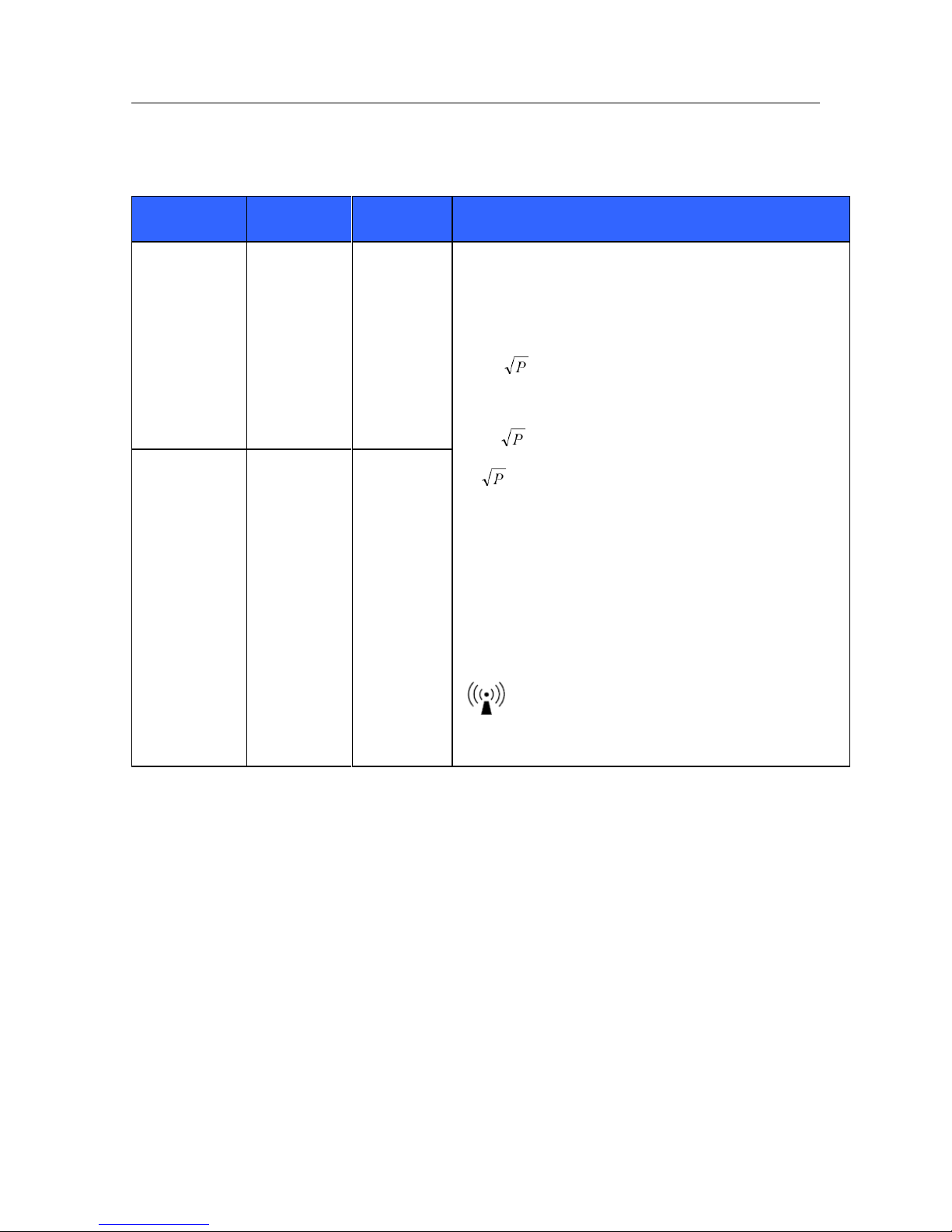
ELECTROMAGNETIC COMPATABILITY (EMC)
23
Table X-3 Guidance and Manufacturer’s Declaration: Electromagnetic Immunity
The equipment is intended for use in the electromagnetic environment specified in the table below. The customer or
the user of the equipment should ensure that it is used in such an environment.
Immunity Test
IEC 60601 Test
Level
Compliance
Level
Electromagnetic Environment: Guidance
Conducted
RF EN
61000-4-6
3 Vrms
150 kHz to
80 MHz
3 Vrms
150 kHz to
80 MHz
Portable and mobile RF communications equipment should be used no
closer to any part of the equipment, including cables, than the
recommended separation distance calculated from the equation
applicable to the frequency of the transmitter.
Recommended separation distance
d = 1.2
d = 1.2 80 MHz to 800 MHz
d = 800 MHz to 2.5 GHz
Where P is the maximum output power rating of the transmitter in
watts (W) according to the transmitter manufacturer and d is the
recommended separation distance in meters (m).
Field strengths from fixed RF transmitters, as determined by an
electromagnetic site surveya, should be less than the compliance level
in each frequency rangeb.
Interference may occur in the vicinity of equipment marked with the
following symbol:
Radiated RF
IEC 61000-43
3 V/m
80 MHz to
2.5 GHz
3 V/m
80 MHz to
2.5 GHz
a. Field strengths from fixed transmitters, such as base stations for radio (cellular/cordless) telephones and land
mobile radios, amateur radios, AM and FM radio broadcast, and TV broadcast cannot be predicted theoretically
with accuracy. To assess the electromagnetic environment due to fixed RF transmitters, an electromagnetic site
survey should be considered. If the measured field strength in the location in which the equipment is used
exceeds the applicable RF compliance level above, the equipment should be observed to verify normal operation.
If abnormal performance is observed, additional measures may be necessary, such as reorienting or relocating the
equipment.
b. Over the frequency range 150 kHz to 80 MHz, field strengths should be less than [3] V/m.
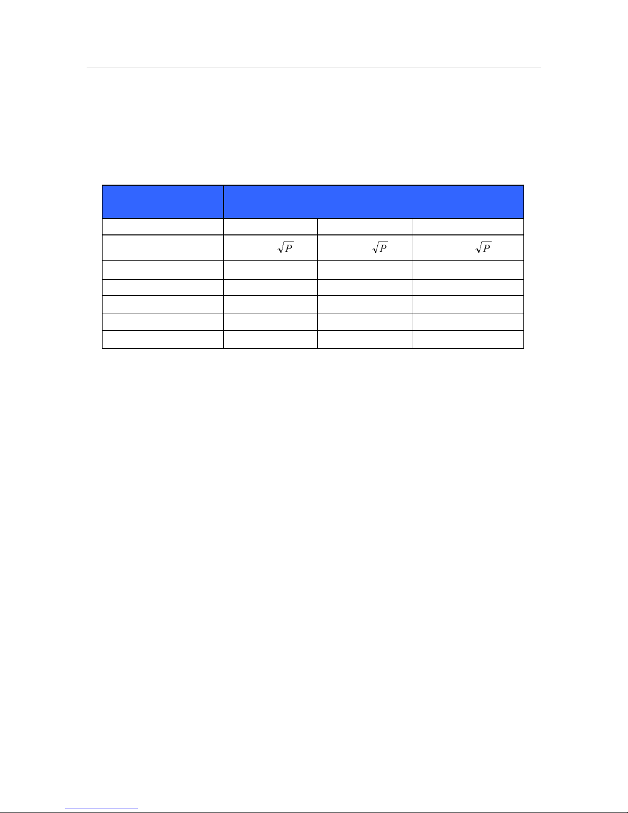
ELECTROMAGNETIC COMPATABILITY (EMC)
24
Table X-4 Recommended Separation Distances Between Portable and Mobile RF Communications
Equipment and the Equipment
The equipment is intended for use in the electromagnetic environment in which radiated RF disturbances are
controlled. The customer or the user of the equipment can help to prevent electromagnetic interference by
maintaining a minimum distance between portable and mobile RF communications equipment (transmitters) and the
equipment as recommended in the table below, according to the maximum output power of the communications
equipment.
Rated Maximum Output
Power of Transmitter (W)
Separation Distance According to Frequency of Transmitter (m)
150 KHz to 80 MHz
80 MHz to 800 MHz
800 MHz to 2.5 GHz
d = 1.2
d = 1.2
d = 2.3
0.01
0.12 m
0.12 m
0.23 m
0.1
0.38 m
0.38 m
0.73 m
1
1.2 m
1.2 m
2.3 m
10
3.8 m
3.8 m
7.3 m
100
12.0 m
12.0 m
23.0 m
For transmitters rated at a maximum output power not listed above, the recommended separation distance d in meters
(m) can be estimated using the equation applicable to the frequency of the transmitter, where P is the maximum
output power rating of the transmitter in watts (W) according to the transmitter manufacturer.
NOTE: At 80 MHz and 800 MHz, the separation distance for the higher frequency range applies.
NOTE: These guidelines may not apply in all situations. Electromagnetic propagation is affected by
absorption and reflection from structures, objects, and people.
 Loading...