

Mortara ELI 380 User Manual
TABLE OF CONTENTS
iii
REF 9515-189-50-ENG Rev G1
ELI 380
RESTING ELECTROCARDIOGRAPH
USER MANUAL
Manufactured by Mortara Instrument, Inc., Milwaukee, Wisconsin U.S.A.
CAUTION: Federal law restricts this device to sale by or on the order of a physician.

Copyright © 2017
by Mortara Instrument, Inc.
7865 N. 86th Street
Milwaukee, Wisconsin 53224
E-mail: techsupport@mortara.com
This document contains confidential information that belongs to Mortara Instrument, Inc. No part of this document
may be transmitted, reproduced, used, or disclosed outside of the receiving organization without the express written
consent of Mortara Instrument, Inc. Mortara is a registered trademark of Mortara Instrument, Inc. AM12, ELI,
VERITAS, and WAM are trademarks of Mortara Instrument, Inc. DICOM is the registered trademark of the
National Electrical Manufacturers Association for its standards publications relating to digital communications of
medical information. V2.3.0 2017-08

TABLE OF CONTENTS
1.
GENERAL STATEMENTS ................................................................................................................. i
TECHNICAL SUPPORT AND SERVICE ...................................................................................................................................... i
2.
NOTICES ........................................................................................................................................... ii
MANUFACTURER’S RESPONSIBILITY ..................................................................................................................................... ii
RESPONSIBILITY OF THE CUSTOMER..................................................................................................................................... ii
EQUIPMENT IDENTIFICATION ............................................................................................................................................. ii
COPYRIGHT AND TRADEMARK NOTICES ................................................................................................................................ ii
OTHER IMPORTANT INFORMATION ..................................................................................................................................... ii
3.
WARRANTY INFORMATION ........................................................................................................... iii
YOUR MORTARA WARRANTY ........................................................................................................................................... iii
4.
USER SAFETY INFORMATION ........................................................................................................ 1
WARNINGS .................................................................................................................................................................... 1
CAUTIONS ..................................................................................................................................................................... 4
FCC COMPLIANCE STATEMENT FOR THE WAM .................................................................................................................... 5
INDUSTRY CANADA COMPLIANCE STATEMENT ............................................................................................................................ 5
NOTES .......................................................................................................................................................................... 6
5.
EQUIPMENT SYMBOLS AND MARKINGS...................................................................................... 9
SYMBOL DELINEATION ................................................................................................................................................... 10
DISPLAY ICONS AND KEYBOARD BUTTONS .......................................................................................................................... 10
6.
GENERAL CARE ............................................................................................................................. 11
PRECAUTIONS .............................................................................................................................................................. 11
INSPECTION ................................................................................................................................................................. 11
CLEANING LEAD WIRES AND CABLES, PATIENT ACQUISITION DEVICE AND ELECTROCARDIOGRAPH .................................................. 11
7.
ELECTROMAGNETIC COMPATIBILITY (EMC) ............................................................................ 13
GUIDANCE AND MANUFACTURER’S DECLARATION: ELECTROMAGNETIC EMISSIONS .................................................................... 14
GUIDANCE AND MANUFACTURER’S DECLARATION: ELECTROMAGNETIC IMMUNITY .................................................................... 15
GUIDANCE AND MANUFACTURER’S DECLARATION: ELECTROMAGNETIC IMMUNITY .................................................................... 16
RECOMMENDED SEPARATION DISTANCES BETWEEN PORTABLE AND MOBILE RF COMMUNICATIONS EQUIPMENT AND THE EQUIPMENT 16
8.
INTRODUCTION .............................................................................................................................. 17
MANUAL PURPOSE ....................................................................................................................................................... 17
AUDIENCE ................................................................................................................................................................... 17
INDICATIONS FOR USE ................................................................................................................................................... 17
SYSTEM DESCRIPTION .................................................................................................................................................... 18
SYSTEM ILLUSTRATION ................................................................................................................................................... 19
SIDE VIEW ................................................................................................................................................................... 19
REAR VIEW .................................................................................................................................................................. 20
BASE VIEW .................................................................................................................................................................. 20
SWIVEL TOUCHSCREEN MODEL ........................................................................................................................................ 21
ELI 380 CAPACITIVE-TOUCH GLASS KEYBOARD WITH TOUCHPAD ........................................................................................... 21
CLEANING MODE .......................................................................................................................................................... 21
NAVIGATION OVERVIEW ................................................................................................................................................. 21

POWER STATUS ............................................................................................................................................................ 22
SYMBOLS ENTRY ........................................................................................................................................................... 22
DISPLAY OVERVIEW ....................................................................................................................................................... 23
Display Parameters .................................................................................................................................................. 24
Function Control Icons .............................................................................................................................................. 25
SPECIFICATIONS ............................................................................................................................................................ 27
ACCESSORIES ............................................................................................................................................................... 28
Replacement Lead Sets and Accessories................................................................................................................... 28
Paper ........................................................................................................................................................................ 28
Electrodes ................................................................................................................................................................. 29
Acquisition Modules ................................................................................................................................................. 29
Power Cords ............................................................................................................................................................. 29
Manuals ................................................................................................................................................................... 29
Miscellaneous........................................................................................................................................................... 29
9.
EQUIPMENT PREPARATION ......................................................................................................... 31
INITIAL STARTUP ........................................................................................................................................................... 31
CONFIGURING THE AMXX ACQUISITION MODULE ............................................................................................................... 31
CONFIGURING THE WAM WIRELESS ACQUISITION MODULE ................................................................................................. 31
ELI 380 CONFIGURATION FOR ALL USERS .......................................................................................................................... 33
LOADING PAPER ........................................................................................................................................................... 34
POWERING THE ELI 380 ................................................................................................................................................ 35
Operating on AC Power ............................................................................................................................................ 36
Battery Operation ..................................................................................................................................................... 36
POWER STATUS ............................................................................................................................................................ 40
Powered by AC ......................................................................................................................................................... 36
Powered by Battery .................................................................................................................................................. 36
Standby .................................................................................................................................................................... 36
Reboot ...................................................................................................................................................................... 36
POWER OFF ................................................................................................................................................................. 36
10.
RECORD AN ECG ........................................................................................................................... 37
PATIENT PREPARATION .................................................................................................................................................. 37
Preparing Patient Skin .............................................................................................................................................. 37
PATIENT HOOKUP ......................................................................................................................................................... 37
To Attach the Electrodes .......................................................................................................................................... 37
Alternate 12-Lead Placement ................................................................................................................................... 40
PATIENT DEMOGRAPHIC ENTRY ....................................................................................................................................... 41
Patient Demographic Formats ................................................................................................................................. 41
Manually Entering Patient Demographics ............................................................................................................... 41
Automatically Entering Patient Demographics from the ECG Directory ................................................................... 42
Automatically Entering Patient Demographics from the MWL (Modality Worklist) ................................................. 42
Automatically Entering Patient Demographics from the Patient List ....................................................................... 43
Automatically Entering Patient Demographics using the Optional Bar Code Scanner ............................................. 43
ECG Display Setup—Individual ECG .......................................................................................................................... 44
ECG ACQUISITION AND PRINTING WITH WAM OR AMXX..................................................................................................... 45
ECG Acquisition......................................................................................................................................................... 45
ECG Electrode Placement Troubleshooting .............................................................................................................. 46
ECG Screen Notification Messages ........................................................................................................................... 46
Critical Test Result Notification ................................................................................................................................ 47
Printing a Rhythm Strip ............................................................................................................................................ 48
Acquiring a STAT ECG ............................................................................................................................................... 48
TABLE OF CONTENTS

Editing Patient Demographics in a Stored ECG Record ............................................................................................ 49
Erasing Stored ECG Records ..................................................................................................................................... 49
BEST 10 SECOND ECG ................................................................................................................................................... 49
Changing Best 10 or Last 10 ..................................................................................................................................... 50
ECG Selection from Full Disclosure ........................................................................................................................... 50
11.
CONNECTIVITY AND ECG TRANSMISSION ................................................................................ 51
ECG TRANSMISSION ...................................................................................................................................................... 51
Transmitting Records to ELI Link .............................................................................................................................. 51
TRANSMISSION MEDIA AUTO SYNC .................................................................................................................................. 51
Transmission Using the USB Device Port to a PC ...................................................................................................... 51
USB DEVICE CONNECTION .............................................................................................................................................. 51
Transmission Using the USB Host Port to a USB Memory Stick ................................................................................ 51
Transferring Individual Patient Records to the USB Memory Stick ........................................................................... 52
Transferring Batch Patient Records to the USB Memory Stick ................................................................................. 52
Connecting the ELI 380 to a PC ................................................................................................................................. 52
Transmitting Patient Records to ELI Link .................................................................................................................. 52
12.
ECG DIRECTORY, MWL, AND THE PATIENT LIST ..................................................................... 53
ECG REVIEW AND MANAGEMENT .................................................................................................................................... 53
REVIEWING ECG RECORDS ............................................................................................................................................. 53
ERASING ECG RECORDS FROM THE DIRECTORY ................................................................................................................... 56
MWL ECG ORDERS ...................................................................................................................................................... 57
SYNCHRONIZE FUNCTION ................................................................................................................................................ 57
MWL QUERY CODE FUNCTION ....................................................................................................................................... 57
SEARCHING ECG ORDERS ............................................................................................................................................... 57
PATIENT LIST ................................................................................................................................................................ 59
SEARCHING THE PATIENT LIST .......................................................................................................................................... 59
PRINTING THE ECG DIRECTORY, MWL ORDERS, OR THE PATIENT LIST .................................................................................... 59
13.
CONFIGURATION SETTINGS ........................................................................................................ 61
MENU COMMANDS AND UTILITIES ................................................................................................................................... 61
Table of Utility Descriptions and Access Requirement.............................................................................................. 61
CONFIGURATION MENU: ABOUT ..................................................................................................................................... 64
CONFIGURATION MENU: CUSTOM ID..................................................................................................................................... 66
CONFIGURATION MENU: DATE/TIME ............................................................................................................................... 66
CONFIGURATION MENU: WAM/AM-XX ......................................................................................................................... 67
CONFIGURATION MENU: NETWORK ................................................................................................................................. 67
CONFIGURATION MENU: PRINT ...................................................................................................................................... 67
CONFIGURATION MENU: OPTIONS CODE .......................................................................................................................... 67
CONFIGURATION MENU: SYSTEM .................................................................................................................................... 68
CONFIGURATION MENU: ECG ........................................................................................................................................ 70
CONFIGURATION MENU: ALTERNATE PLACEMENT .............................................................................................................. 73
CONFIGURATION MENU: LOCAL AREA NETWORK (LAN) CONNECTION AND SETUP .................................................................... 73
Ethernet Transmission Status Indicator LEDs ........................................................................................................... 74
CONFIGURATION MENU: WIRELESS LOCAL AREA NETWORK (WLAN) CONNECTION AND SETUP .................................................. 74
Testing RF Signal Strength ........................................................................................................................................ 76
CONFIGURATION MENU: PASSWORDS .............................................................................................................................. 76
Setting Passwords .................................................................................................................................................... 76
CONFIGURATION SETTINGS: SERVICE ...................................................................................................................................... 76
14.
MAINTENANCE AND TROUBLESHOOTING ................................................................................ 77
SYSTEM TROUBLESHOOTING CHART .................................................................................................................................. 77

ECG TROUBLESHOOTING CHART ...................................................................................................................................... 77
TRANSMISSION TROUBLESHOOTING CHART ........................................................................................................................ 78
DISPLAY TROUBLESHOOTING CHART ................................................................................................................................. 80
REBOOT THE DEVICE ............................................................................................................................................................. 81
TEST OPERATION .......................................................................................................................................................... 81
RECOMMENDATIONS TO BIOMEDICAL STAFF ....................................................................................................................... 81
CLEANING THE THERMAL PRINTER .................................................................................................................................... 81
To Clean the Printer .................................................................................................................................................. 81
To Clean the Print Head ............................................................................................................................................ 81

TABLE OF FIGURES
Figure 1 ELI 380 Front ................................................................................................................................................ 23
Figure 2 ELI 380 Side with Writer Handle .................................................................................................................. 23
Figure 3 ELI 380 Rear with Connector Ports ............................................................................................................... 24
Figure 4 ELI 380 Base with Battery Compartment ...................................................................................................... 24
Figure 5 ELI 380 Keyboard ......................................................................................................................................... 25
Figure 6 Optional ELI 380 Touchscreen
Figure 7 ELI 380 Home Display with Full Disclosure ................................................................................................. 27
Figure 8 ELI 380 AM12 Connection ............................................................................................................................ 35
Figure 9 ELI 380 Paper Loading .................................................................................................................................. 38

TABLE OF FIGURES

Tel:
414.354.1600
Tel:
800.231.7437
Fax:
414.354.4760
Internet:
http://www.mortara.com
1. GENERAL STATEMENTS
Technical Support and Service
Headquarters
Mortara Instrument, Inc.
7865 North 86th Street
Milwaukee, WI 53224
U.S.A.
European Union
Representative
Mortara Instrument Europe, s.r.l.
(European Headquarters)
Via Cimarosa 103/105
40033 Casalecchio di Reno (BO)
Italy
Tel:
Fax:
Service/Technical
Support Group
Mortara Instrument, Inc.
7865 North 86th Street
Milwaukee, WI 53224
U.S.A.
Tel: 414.354.1600
Service:
Fax:
E-mail: techsupport@mortara.com
+39.051.298.7811
+39.051.613.3582
888.MORTARA
(888.667.8272)
414.501.7977
Sales Support/
Supplies & Accessories
Mortara Instrument, Inc.
7865 North 86th Street
Milwaukee, WI 53224
U.S.A.
Tel: 414.354.1600
Fax:
414.354.4760
Hospital Customers: orders.us@mortara.com
Physician Practice: orderspc.us@mortara.com
U.S. Distribution: orderspc.us@mortara.com
Mortara Instrument Germany
Bonifaciusring 15
45309 Essen
Germany
Tel:
Fax:
+49.201.18 55 69 70
+49.201.18 55 69 77
Mortara Instrument Netherlands
Postbus 324
5680 AH Best
Industrieweg 160b
5683 CG Best
Netherlands
Tel:
Fax:
+31.499.377310
+31.499.377908
Mortara Instrument Australia
PO Box 7568
Baulkham Hills NSW 2153
Unit 28, 9 Hoyle Avenue
Castle Hill NSW 2154
Australia
Tel:
Fax:
+61 2 8070 9303
+61 2 9899 9478
Mortara Instrument UK Ltd
Units 11 & 12, Scion House
Stirling University Innovation Park
Stirling FK9 4NF
Scotland
Tel:
Fax:
+44.1786.444980
+44.1786.446630
i

2. NOTICES
Manufacturer’s Responsibility
Mortara Instrument, Inc. is responsible for the effects on safety and performance only if:
•
Assembly operations, extensions, readjustments, modifications, or repairs are carried out only by persons
authorized by Mortara Instrument, Inc.
•
The device is used in accordance with the instructions for use.
Responsibility of the Customer
The user of this device is responsible for ensuring the implementation of a satisfactory maintenance schedule.
Failure to do so may cause undue failure and possible health hazards.
This manual must be kept in a safe place to prevent its deterioration and/or alteration. The user and Mortara
Instrument, Inc. authorized personnel must have access to this manual at any time.
The user of this device must periodically check the accessories, their functionality and integrity.
Equipment Identification
Mortara Instrument, Inc. equipment is identified by a serial and reference number on the bottom of the device. Care
should be taken so that these numbers are not defaced.
Copyright and Trademark Notices
This document contains information that is protected by copyright. All rights are reserved. No part of this
document may be photocopied, reproduced, or translated to another language without prior written consent of
Mortara Instrument, Inc.
Other Important Information
The information in this document is subject to change without notice.
Mortara Instrument, Inc. makes no warranty of any kind with regard to this material including, but not limited to,
implied warranties of merchantability and fitness for a particular purpose. Mortara Instrument, Inc. assumes no
responsibility for any errors or omissions that may appear in this document. Mortara Instrument, Inc. makes no
commitment to update or to keep current the information contained in this document.
ii

3. WARRANTY INFORMATION
Your Mortara Warranty
MORTARA INSTRUMENT, INC. (hereafter referred to as “Mortara”) warrants that components within Mortara
products (hereafter referred to as “Product/s”) will be free from defects in workmanship and materials for the
number of years specified on documentation accompanying the product, or previously agreed to by the purchaser
and Mortara, or if not otherwise noted, for a period of twenty-four (24) months from the date of shipment.
Consumable, disposable or single use products such as, but not limited to, PAPER or ELECTRODES are warranted
to be free from defects in workmanship and materials for a period of 90 days from the date of shipment or the date
of first use, whichever is sooner.
Reusable product such as, but not limited to, BATTERIES, BLOOD PRESSURE CUFFS, BLOOD PRESSURE
HOSES, TRANSDUCER CABLES, Y-CABLES, PATIENT CABLES, LEAD WIRES, MAGNETIC STORAGE
MEDIUMS, CARRY CASES or MOUNTS, are warranted to be free from defects in workmanship and materials for
a period of 90 days. This warranty does not apply to damage to the Product/s caused by any or all of the following
circumstances or conditions:
a) Freight damage;
b) Parts and/or accessories of the Product/s not obtained from or approved by Mortara;
c) Misapplication, misuse, abuse, and/or failure to follow the Product/s instruction sheets and/or information
guides;
d) Accident; a disaster affecting the Product/s;
e) Alterations and/or modifications to the Product/s not authorized by Mortara;
f) Other events outside of Mortara’s reasonable control or not arising under normal operating conditions.
THE REMEDY UNDER THIS WARRANTY IS LIMITED TO THE REPAIR OR REPLACEMENT WITHOUT
CHARGE FOR LABOR OR MATERIALS, OR ANY PRODUCT/S FOUND UPON EXAMINATION BY
MORTARA TO HAVE BEEN DEFECTIVE. This remedy shall be conditioned upon receipt of notice by Mortara
of any alleged defects promptly after discovery thereof within the warranty period. Mortara’s obligations under the
foregoing warranty will further be conditioned upon the assumption by the purchaser of the Product/s (i) of all
carrier charges with respect to any Product/s returned to Mortara’s principal place or any other place as specifically
designated by Mortara or an authorized distributor or representative of Mortara, and (ii) all risk of loss in transit. It
is expressly agreed that the liability of Mortara is limited and that Mortara does not function as an insurer. A
purchaser of a Product/s, by its acceptance and purchase thereof, acknowledges and agrees that Mortara is not liable
for loss, harm, or damage due directly or indirectly to an occurrence or consequence therefrom relating to the
Product/s. If Mortara should be found liable to anyone under any theory (except the expressed warranty set forth
herein) for loss, harm, or damage, the liability of Mortara shall be limited to the lesser of the actual loss, harm, or
damage, or the original purchase price of the Product/s when sold.
iii

WARRANTY INFORMATION
EXCEPT AS SET FORTH HEREIN WITH RESPECT TO REIMBURSEMENT OF LABOR CHARGES, A
PURCHASER’S SOLE EXCLUSIVE REMEDY AGAINST MORTARA FOR CLAIMS RELATING TO THE
PRODUCT/S FOR ANY AND ALL LOSSES AND DAMAGES RESULTING FROM ANY CAUSE SHALL BE
THE REPAIR OR REPLACEMENT OF DEFECTIVE PRODUCT/S TO THE EXTENT THAT THE DEFECT IS
NOTICED AND MORTARA IS NOTIFIED WITHIN THE WARRANTY PERIOD. IN NO EVENT,
INCLUDING THE CLAIM FOR NEGLIGENCE, SHALL MORTARA BE LIABLE FOR INCIDENTAL,
SPECIAL, OR CONSEQUENTIAL DAMAGES, OR FOR ANY OTHER LOSS, DAMAGE, OR EXPENSE OF
ANY KIND, INCLUDING LOSS OF PROFITS, WHETHER UNDER TORT, NEGLIGENCE OR STRICT
LIABILITY THEORIES OF LAW, OR OTHERWISE. THIS WARRANTY IS EXPRESSLY IN LIEU OF ANY
OTHER WARRANTIES, EXPRESS OR IMPLIED, INCLUDING, BUT NOT LIMITED TO THE IMPLIED
WARRANTY OF MERCHANTABILITY AND THE WARRANTY OF FITNESS FOR A PARTICULAR
PURPOSE.
iv

Warning:
Means there is the possibility of personal injury to you or others.
Caution:
Means there is the possibility of damage to the device.
Note:
Provides information to further assist in the use of the device.
Warnings
4. USER SAFETY INFORMATION
NOTE: This manual may contain screen shots and pictures. Any screen shots and pictures are provided
for reference only. Consult the actual screen in the host language for specific wording.
1. This manual gives important information about the use and safety of this device. Deviating from operating
procedures, misuse or misapplication of the device, or ignoring specifications and recommendations could
result in increased risk of harm to users, patients and bystanders, or damage to the device.
2. Device captures and presents data reflecting a patient’s physiological condition that when reviewed by a trained
physician or clinician can be useful in determining a diagnosis; however, the data should not be used as a sole
means for determining a patient’s diagnosis.
3. Users are expected to be licensed clinical professionals knowledgeable about medical procedures and patient
care, and adequately trained in the use of this device. Before attempting to use this device for clinical
applications, the operator must read and understand the contents of the user manual and other accompanying
documents. Inadequate knowledge or training could result in increased risk of harm to users, patients and
bystanders, or damage to the device. Contact Mortara service for additional training options.
4. To ensure that electrical safety is maintained during operation from AC (~) power, the device must be plugged
into a hospital-grade outlet.
5. Only use parts and accessories supplied with the device and/or are available through Mortara Instrument, Inc.
6. Mortara acquisition modules intended for use with the device include series resistance (9 Kohm minimum) in
each lead for defibrillation protection. Acquisition modules should be checked for cracks or breakage prior to
use.
7. The ELI 380 uses lithium-ion batteries. The following precautions should be taken regarding the batteries:
o
Do not immerse the device in water.
o
Do not heat or throw the device in fire.
o
Do not leave the device in conditions over 60 ºC or in a heated car.
o
Do not attempt to crush or drop the device.
o
Only use the approved Mortara battery pack with the ELI 380.
o
Follow the disposal instructions in the ELI 380 Service Manual when the device is taken out of service.
8. The ELI 380 battery/batteries must be initially fully charged prior to use. Ideally, the battery/batteries must be
fully charged and fully discharged several times to allow for optimal performance.
9. Portions of the device are constructed from glass. If the machine is dropped, or otherwise impacted this glass
can shatter. Broken glass can cause injurious cuts.
1

USER SAFETY INFORMATION
10. The movable touchscreen display can pinch fingers when closing. Use caution when closing and opening the
display.
11. Conductive parts of the acquisition module(s), electrodes, and associated connections of type CF applied parts,
including the neutral conductor of the acquisition module(s) and electrodes, should not come into contact with
other conductive parts including earth ground.
12. ECG electrodes could cause skin irritation; patients should be examined for signs of irritation or inflammation.
13. To avoid the possibility of serious injury or death during patient defibrillation, do not come into contact with the
device or acquisition module(s). Additionally, proper placement of defibrillator paddles in relation to the
electrodes is required to minimize harm to the patient.
14. This device does not automatically switch between direct or wireless acquisition modules. Clinician must
choose the type of acquisition module before ECG acquisition. If your device is equipped with a receiver for a
wireless acquisition module, always make sure that you are receiving data from the expected module.
15. This device was designed to use the electrodes specified in this manual. Proper clinical procedure must be
employed to prep the electrode sites and to monitor the patient for excessive skin irritation, inflammation, or
other adverse reactions. Electrodes are intended for short-term use and should be removed from the patient
promptly following testing.
16. To avoid potential for spread of disease or infection, single-use disposable components (e.g., electrodes) must
not be reused. To maintain safety and effectiveness, electrodes must not be used beyond their expiration date.
17. A possible explosion hazard exists. Do not use the device in the presence of a flammable anesthetic mixture.
18. Where the integrity of external protective earth conductor arrangement is in doubt, the device shall be operated
from its internal electrical power source.
19. Medical devices have been designed to have a higher degree of protection against electric shock than, for
instance, information technology equipment because patients often are connected to multiple devices and also
may be more prone to the adverse effect of electric currents than healthy persons. All equipment that is
connected to the patient, can be touched by the patient, or can be touched by another person while th at person
touches the patient at the same time, should have the same level of protection against electric shock as medical
equipment. The ELI 380 is a medical device that has been designed to be connected to other devices for the
purpose of receiving and transmitting data. Certain measures must be taken to prevent the risk of excessive
electric current flow through the operator or patient when connected:
All electrical equipment that is not medical electrical equipment must be placed outside of the “patient
environment,” defined by applicable safety standards to be at least 1.5 meters (5 feet) from the patient.
Alternatively, non-medical equipment may be provided with additional protection such as an additional
protective earth connection.
All medical electrical equipment that has a physical connection to the ELI 380 or the patient, or is in the
patient environment must comply with applicable safety standards for medical electrical devices.
All electrical equipment that is not medical electrical equipment and has a physical connection to the
ELI 380 must comply with applicable safety standards, such as IEC 60950 for information technology
equipment. This includes information network equipment connected through the LAN connector.
Conductive (metal) parts that can be touched by the operator in normal use and that are connected to non-
medical equipment should not be brought into the patient environment. Examples are connectors for
shielded Ethernet or USB cables.
2

USER SAFETY INFORMATION
If multiple devices are connected to each other or to the patient, device chassis and patient leakage currents
may be increased, and should be measured for compliance with applicable standards for medical electrical
systems.
Avoid the use of portable multiple socket outlets. If used and not compliant with medical electrical
device standards, an additional protective earth connection is required.
To prevent electric shock due to unequal ground potentials that may exist between points of a distributed
network system or fault conditions in external network connected equipment, network cable shielding
(where used) must be connected to protective earth ground appropriate to the area where the device is used.
20. The device has not been designed for use with high-frequency (HF) surgical equipment and does not provide a
protective means against hazards to the patient.
21. When the 40 Hz filter is used, the frequency response requirement for diagnostic ECG equipment cannot be
met. The 40 Hz filter significantly reduces high-frequency components of the ECG and pacemaker spike
amplitudes, and is recommended only if high-frequency noise cannot be reduced by proper procedures.
22. Other medical equipment, including but not limited to defibrillators and ultrasound machines, may cause
interference with the ECG signals recorded by the device.
23. For proper operation and the safety of users or patients and bystanders, equipment and accessories must be
connected only as described in this manual. Do not connect a telephone line cable to the LAN connector.
24. Unauthorized connection to IT networks could result in previously unidentified risks to patients, operators, or
third parties. The manufacturer is not liable for these additional risks, as the identification, analysis, evaluation,
and control should be conducted by the responsible organization. Changes to the IT network could also
introduce new risks that require additional analysis. This includes changes in network configuration, connection
of additional items, disconnection of items, update of equipment, and upgrade of equipment.
25. Some Mortara electrocardiographs can be equipped with a wireless LAN (WLAN) module for transmitting
ECG records. Device labeling will indicate if your device is equipped with such a module. If so equipped, the
following notices apply:
The WLAN identification can be found on a label on the bottom of the device.
Quatech, Inc. Model WLNN-AN-MR551
(model subject to change without notice)
26. Use of the WLAN module may interfere with other equipment operating in the vicinity. Check with local
authorities or spectrum management officials in your facility to determine if restrictions apply to the use of this
feature in your area.
27. To ensure compliance with current regulations limiting both maximum RF output power and human exposure to
radio frequency radiation, a separation distance of at least 20 cm must be maintained between the device and the
head and body of the user and any nearby persons at all times.
28. The WLAN module complies with applicable RF safety standards including standards and recommendations for
the protection of public exposure to RF electromagnetic energy that have been established by governmental
bodies and other qualified organizations, such as the following:
Federal Communications Commission (FCC)
Directives of the European Community
Directorate General V in Matters of Radio Frequency Electromagnetic Energy
3

USER SAFETY INFORMATION
Cautions
1.
Do not attempt to clean the device or acquisition module by submersing into a liquid, autoclaving, or steam
cleaning as this may damage equipment or reduce its usable life. Use of unspecified cleaning/disinfecting
agents, failure to follow recommended procedures, or contact with unspecified materials could result in
increased risk of harm to users, patients and bystanders, or damage to the device.
2.
No user-serviceable parts inside. Screw removal by qualified service personnel only. Damaged or suspected
inoperative equipment must be immediately removed from use and must be checked/repaired by qualified
service personnel prior to continued use.
3. The rechargeable internal battery is a sealed lithium-ion type. If the battery appears to become defective, refer
to Mortara Technical Support.
4. Do not pull or stretch the acquisition module lead wires and cable as this could result in mechanical and/or
electrical failures.
5. Proper functioning backup items such as spare lead wires, front-end device, and other equipment are
recommended on hand to prevent delayed treatment due to an inoperable device.
6. The WAM will only work with receiving devices that are equipped with the appropriate option.
7. No user-serviceable parts are inside the WAM. Damaged or suspected inoperative equipment must be
immediately removed from use and must be checked/repaired by qualified service personnel prior to continued
use.
8. This WAM is not recommended for use in the presence of imaging equipment such as Magnetic Resonance
Imaging (MRI) and Computed Tomography (CT) devices, etc.
9. The following equipment may cause interference with the WAM RF channel: microwave ovens, diathermy
units with LANs (spread spectrum), amateur radios, and government radar.
10. When necessary, dispose of the device, its components and accessories (e.g., batteries, cables, electrodes),
and/or packing materials in accordance with local regulations.
11. AA batteries are known to leak their contents when stored in unused equipment. Remove battery from WAM
when not used for an extended period of time.
12. Be careful to insert the connector block into the appropriate input connector by matching the lead wire labels to
the WAM or AMxx label. (AMxx refers to USB equipped acquisition modules. Examples of AMxx
acquisition modules include AM15E, AM12M, and AM12).)
4

USER SAFETY INFORMATION
FCC Compliance Statement for the WAM
In the United States use of this device is regulated by the Federal Communications Commission (FCC). The WAM
with its antenna complies with FCC’s RF exposure limits for general population/uncontrolled exposure.
FCC Warning (Part 15.21): Changes or modifications not expressly approved by the party responsible for
compliance could void the user’s authority to operate the device.
WAM FCC ID: HJR-WAM2500
UTK FCC ID: HJR-UTK2500
These devices comply with Part 15 of the FCC rules. Operation is subject to the following conditions:
1. This device may not cause harmful interference, and
2. This device must accept any interference received, including interference that may cause undesired operation.
Industry Canada Compliance Statement
These devices comply with RSS-210 of the Industry Canada rules. Operation is subject to the following two
conditions:
1. This device may not cause interference, and
2. This device must accept any interference, including interference that may cause undesired operation of the device.
WAM IC: 3758B-WAM2500
UTK IC: 3758B-UTK2500
The term “IC:” before the certification/registration number only signifies that the Industry Canada technical
specifications were met.
5

USER SAFETY INFORMATION
Notes
1. Patient movement may generate excessive noise that may affect the quality of the ECG traces and the proper
analysis performed by the device.
2. Proper patient preparation is important to proper application of ECG electrodes and operation of the device.
3. The algorithm detecting electrode reversal is based on normal physiology and ECG lead order, and tries to
identify the most likely switch; however, it is advisable to check the other electrode positions in the same group
(limb or chest).
4. There is no known safety hazard if other equipment, such as pacemakers or other stimulators, is used
simultaneously with the device; however, disturbance to the signal may occur.
5. The WAM LEDs will automatically start flashing if the batteries have been discharged below 1.0 volts.
6. During normal WAM/AMxx operation, the green LED will display continuously.
7. If the WAM battery cover is opened during transmission, the device will stop transmitting. The battery must be
reinserted and the cover must be applied to resume operation.
8. The WAM will automatically turn off (LEDs off) if the battery has been severely discharged.
9. The WAM will automatically turn off when the electrocardiograph is powered down.
10. The WAM will automatically turn off after being disconnected from the patient. This will happen regardless of
ELI 380 battery/AC power state.
11. The display of absent waveform while using the WAM wireless acquisition module could be due to the WAM
being turned off or having no battery, or the WAM being out of range or experiencing a calibration error.
Review the LED indicator on the WAM to ensure the unit is turned on and has proper battery level. Ensure the
WAM is paired correctly and is within recommended proximity of the electrocardiograph, and/or power cycle
the WAM to re-calibrate.
12. The display of absent waveform display while using the AMxx acquisition module could be due to an improper
auto-calibration. Reconnect the AMxx or power cycle the electrocardiograph.
13. Square waves on the display and rhythm printout could be due to the WAM or the AMxx lead wires not being
connected to the patient.
14. As defined by IEC 60601-1 and IEC 60601-2-25, the device is classified as follows:
Class I equipment or internally powered.
Type CF defibrillation-proof applied parts.
Ordinary equipment.
Equipment not suitable for use in the presence of a flammable anesthetic mixture.
Continuous operation.
NOTE: From a safety perspective, per IEC 60601-1 and derivative standards/norms, this device is
declared to be “Class I” and uses a three-prong inlet to ensure an earth connection is made along with
mains. The ground terminal on the mains inlet is the only protective earth point in the device. Exposed
metal accessible during normal operation is double insulated from mains. Internal connections to earth
ground are functional earth.
6

USER SAFETY INFORMATION
15. This device is intended to be used in a hospital or doctor’s office setting, and should be used and stored
according to the environmental conditions specified below:
Operating temperature: +10° to +40°C (+50° to +104°F)
Operating humidity: 10% to 95% RH, non-condensing
Storage temperature: -40° to +70°C (-40° to +158°F)
Storage humidity: 10% to 95% RH, non-condensing
Atmospheric pressure: 500 hPa to 1060 hPa
16. The device will automatically turn off (blank screen) if the batteries have been severely discharged and the AC
mains is disconnected from the device.
17. After operating the device using battery power, always reconnect the power cord. This ensures that the batteries
will be automatically recharged for the next time you use the device. A light next to the on/off switch will
illuminate indicating that the device is charging.
18. When using the WAM, it must be paired to electrocardiograph before operation.
19. The device is UL classified:
WITH RESPECT TO ELECTRIC SHOCK,
FIRE AND MECHANICAL HAZARDS ONLY IN ACCORDANCE WITH
AAMI ES 60601-1(2012), CAN/CSA C22.2 No. 60601-1(2014), IEC
60601-1(2012), AND IEC 60601-2-25(2011)
20. The WAM is UL classified:
WITH RESPECT TO ELECTRIC SHOCK,
FIRE AND MECHANICAL HAZARDS ONLY IN ACCORDANCE WITH
UL2601-1, IEC60601-1, CAN/CSA CC22.2 No. 601.1, IEC60601-2-25,
Wireless Data Transmission
21. ELI 380 electrocardiographs are equipped with a wireless data transmission module (WLAN). This technology
uses radios to transmit data to a Mortara receiving application. Due to the nature of radio transmissions, it’s
possible that, due to the characteristics of the environment where the device is located, some other RF sources
may interfere with the transmission generated by the device. Mortara Instrument has tested the coexistence of
the device with other devices that can interfere such as devices using WLAN, Bluetooth radio, and/or cell
phones. Although the current technology allows a very successful rate of transmission, it’s possible that in
some rare occurrences, the system may not perform at its best resulting in a “failed transmission”. When this
occurs, patient data will not be erased from the device nor stored in the receiving application, ensuring that
partial or corrupted data are not made available to the receiving station. If the failure mode persists the user
should move to a position where the WLAN signals may propagate better to allow successful transmissions.
WLAN
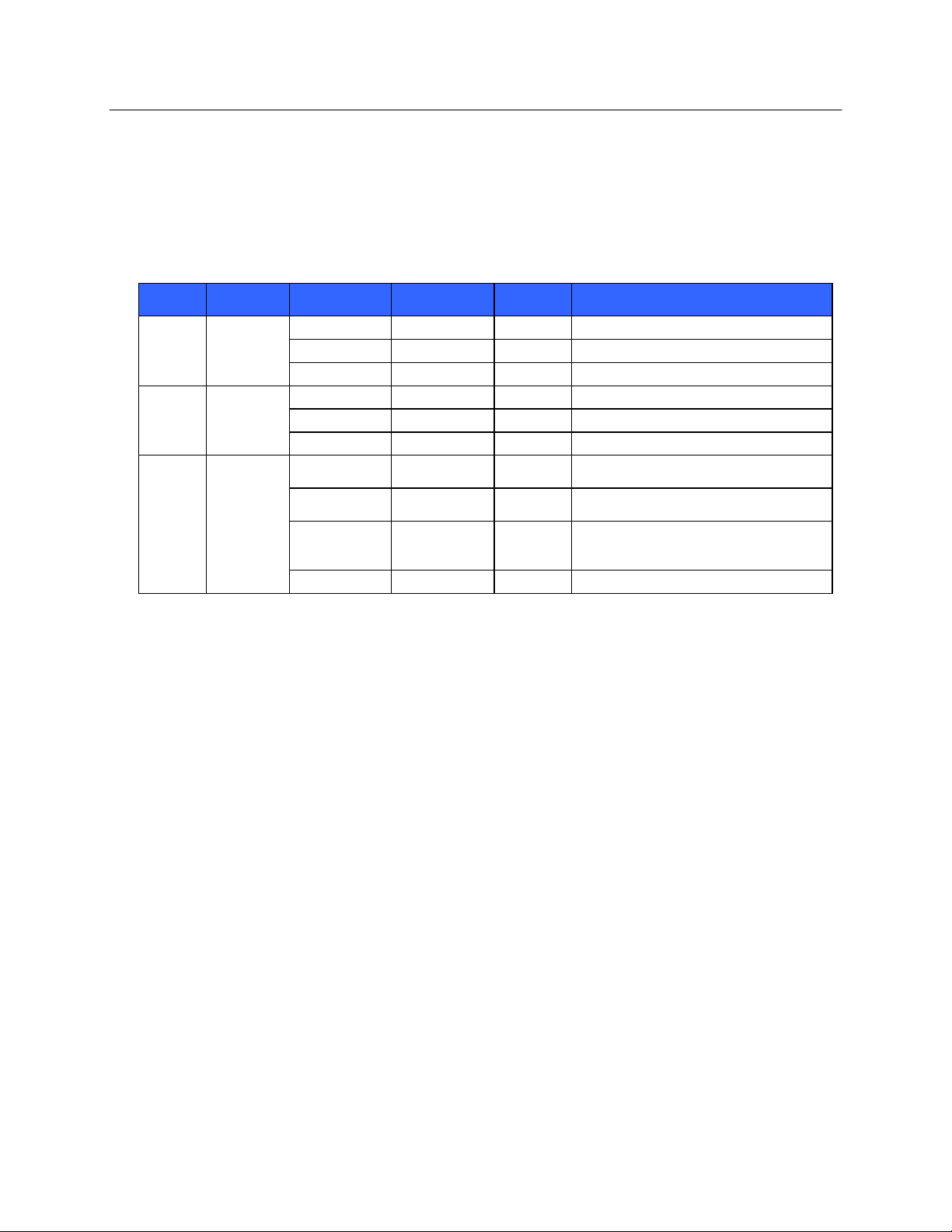
22. Wireless options transmit in the 2.4 GHz or 5 GHz range. Other nearby wireless devices in the same frequency
range may cause interference. If possible, move or turn off other devices to minimize potential interference.
23. The Wireless LAN module used is compliant with the IEEE 802.11 a, b, g and n standards.
7
USER SAFETY INFORMATION
Band
Typical
Power
Region
Frequency
Range (GHz)
No. of
channels
Channel numbers
802.11b
15 dBm /
32 mW
USA/Canada
2.401 - 2.473
11
1 – 11
Europe
2.401 - 2.483
13
1 – 13
Japan
2.401 - 2.495
14
1 – 14
802.11g
13 dBm /
18 mW
USA/Canada
2.401 - 2.473
11
1 – 11
Europe
2.401 - 2.483
13
1 – 13
Japan
2.401 - 2.483
13
1 – 13
802.11a
17 dBm /
USA/Canada
5.15 - 5.35,
13
36,40,44,48,52,56,60,64,149,153,157,
50 mW
5.725 - 5.825
161,165
Europe
5.15 - 5.35,
19
36,40,44,48,52,56,60,64,100,104,108,
5.47 - 5.725
112,116,120,124,128,132,136,140
Japan
4.91 – 4.99,
23
36,40,44,48,52,56,60,64,100,104,108,
5.15 - 5.35,
112,116,120,124,128,132,136,140,184
5.47 - 5.725
188,192,196
China
5.725 - 5.825
5
149,153,157,161,165
24. Access Points used should respect IEEE 802.11 standards as well as local Radio Frequency regulations. The
device will scan the available channels and connect to the Access Point on the channel where the SSID that is
configured on the device is available.
25. The following table shows the radio channels allocated in different geographic areas in the world. For bands
802.11b and g, only channels 1, 6, 11 and 14 (Japan only) are non-overlapping; for band 802-11a, channels
shown represent non-overlapping channel numbers.
26. In order to achieve the best transmission rate, it is necessary that the facility where the device is operated can
provide good area coverage. Please consult the IT personnel of the facility to verify the proper WLAN
availability in the area where the device will be used.
27.
28. RF wave propagation may be blocked or reduced by the environment where the device is used. Most common
areas where this may occur are: shielded rooms, elevators, underground rooms. In all such situations it is
recommended to move the device to a proper location where the WLAN frequencies are available.
8
Caution
Consult accompanying documents
Alternating current
Protective earth symbol (appears on inside of unit)
Fuse symbol (appears on inside of unit)
Network (LAN)
Universal Serial Bus (USB)
Defibrillator-proof type CF applied part
Patient Cable Input
ON/OFF (Standby/power)
Shift key (to enter upper case text on keyboard)
Do not dispose as unsorted municipal waste. Per European Union
Directive 2002/96, requires separate handling for waste disposal according
to national requirements
Indicates compliance to applicable European Union directives
5. EQUIPMENT SYMBOLS AND MARKINGS
Symbol Delineation
9
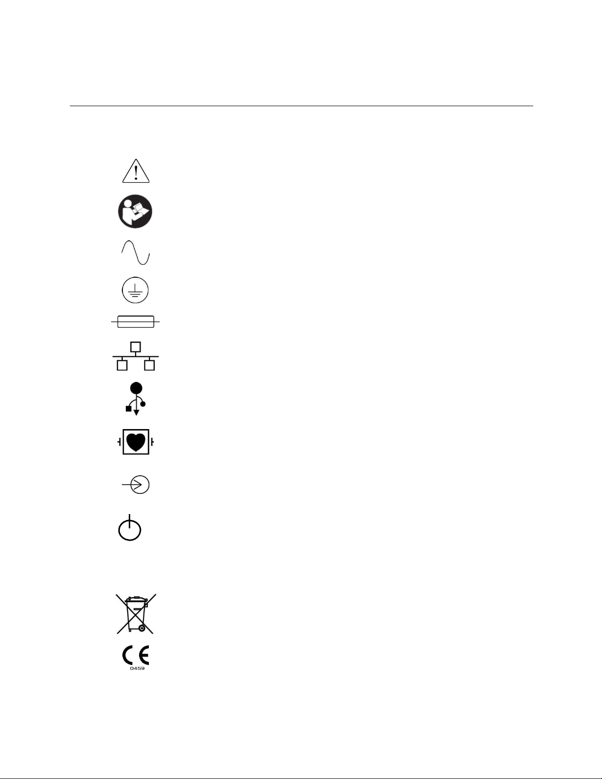
EQUIPMENT SYMBOLS AND MARKINGS
Patient Information
ECG Acquisition
Rhythm Print
Synchronize
Configuration
Home
Full disclosure page up
ECG Acquisition from full disclosure selection
Full disclosure page down
Display Icons and Keyboard Buttons
10
6. GENERAL CARE
Precautions
Power off the device before inspecting or cleaning.
Do not immerse the device in water.
Do not use organic solvents, ammonia-based solutions, or abrasive cleaning agents which may damage
equipment surfaces.
Inspection
Inspect your equipment daily prior to operation. If you notice anything that requires repair, contact an authorized
service person to make the repairs.
Verify that all cords and connectors are securely seated.
Check the case and chassis for any visible damage.
Inspect cords and connectors for any visible damage.
Inspect keys and controls for proper function and appearance.
Cleaning Lead Wires and Cables, Patient Acquisition Device and
Electrocardiograph
1.
Remove cables and lead wires from device before cleaning. Disconnect the power source.
2. For general cleaning of device, display, cables and lead wires, use a soft, lint-free cloth lightly moistened
with a mild soap and water solution. Wipe and air dry.
3. For disinfecting the device, wipe exterior with a soft, lint-free cloth using a solution of Sodium
Hypochlorite (10% household bleach and water solution) minimum 1:500 dilution (minimum 100 ppm free
chlorine) and maximum 1:10 dilution, or a 3% hydrogen peroxide solution.
4. For disinfecting the cables and lead wires, wipe exterior with a soft, lint-free cloth using the same solutions
as for the device, or use highly concentrated (> 70%) isopropanol or ethanol.
5. Use caution with excess liquid as contact with metal parts may cause corrosion.
6. Do not immerse cable ends or lead wires; immersion can cause metal corrosion.
7. Do not use excessive drying techniques such as forced heat.
WARNING: Prevent liquid from penetrating the device and do not attempt to clean/disinfect
the device or patient cables by submerging into a liquid, autoclaving, or steam cleaning. Never expose
cables to strong ultra-violet radiation. Do not sterilize the device or ECG lead wires with Ethylene
Oxide (EtO) gas.
WARNING: Use of unspecified cleaning/disinfecting agents or failure to follow recommended
procedures could result in increased risk of harm to users, patients and bystanders, or damage to the
device.
NOTE: Mortara does not endorse any specific off-the-shelf wipes or liquids. However, products that only
contain the disinfecting agents mentioned above are likely to be compatible with the device. Some products
contain a mixture of agents and may have a detrimental effect if used intensively and frequently. Check the
Material Safety Data Sheet of the product used for the list of ingredients
11
.

GENERAL CARE

7. ELECTROMAGNETIC COMPATIBILITY (EMC)
Electromagnetic compatibility with surrounding devices should be assessed when using the device.
An electronic device can either generate or receive electromagnetic interference. Testing for electromagnetic
compatibility (EMC) has been performed on the device according to the international standard for EMC for medical
devices (IEC 60601-1-2). This IEC standard has been adopted in Europe as the European Norm (EN 60601-1-2).
The device should not be used adjacent to, or stacked on top of other equipment. If the device must be used adjacent
to or stacked on top of other equipment, verify that the device operates in an acceptable manner in the configuration
in which it will be used.
Fixed, portable, and mobile radio frequency communications equipment can affect the performance of medical
equipment. See the appropriate EMC table for recommended separation distances between the radio equipment and
the device.
The use of accessories, transducers, and cables other than those specified by Mortara Instrument may result in
increased emissions or decreased immunity of the equipment.
13

INTRODUCTION
Emissions Test
Compliance
Electromagnetic Environment: Guidance
RF Emissions
CISPR 11
Group 1
The equipment uses RF energy only for its internal function.
Therefore, its RF emissions are very low and not likely to cause
any interference in nearby electronic equipment.
RF Emissions
CISPR 11
Class A
The equipment is suitable for use in all establishments other
than domestic and those directly connected to the public lowvoltage power supply network that supplies buildings used for
domestic purposes.
Harmonic Emissions
IEC 61000-3-2
Complies
Voltage Fluctuations/
Flicker Emissions
IEC 61000-3-3
Complies
Immunity Test
Compliance
Compliance Level
Electromagnetic Environment:
Guidance
Electrostatic
discharge (ESD)
EN 61000-4-2
+/- 6 kV contact
+/- 8 kV air
+/- 6 kV contact
+/- 8 kV air
Floors should be wood, concrete, or
ceramic tile. If floors are covered with
synthetic material, the relative humidity
should be at least 30%.
Electrical fast
transient/burst
EN 61000-4-4
+/- 2 kV for
power supply lines
+/- 1 kV for
input/output lines
+/- 2 kV for
power supply lines
+/- 1 kV for
input/output lines
Mains power quality should be that of a
typical commercial or hospital
environment.
Surge
IEC 61000-4-5
+/- 1 kV differential
mode
+/- 2 kV common mode
+/- 1 kV differential
mode
+/- 2 kV common
mode
Mains power quality should be that of a
typical commercial or hospital
environment.
Voltage dips,
short
interruptions,
and voltage
variations on
power supply
input lines
IEC 61000-4-11
<5% UT
(>95% dip in UT)
for 0.5 cycle
40% UT
(60% dip in UT)
for 5 cycles
<5% UT
(>95% dip in UT)
for 0.5 cycle
40% UT
(60% dip in UT)
for 5 cycles
Mains power quality should be that of a
typical commercial or hospital
environment.
Power frequency
(50/60 Hz)
magnetic field
3 A/m
3 A/m
Power frequency magnetic fields should
be at levels characteristic of a typical
location in a typical commercial or
hospital environment.
Guidance and Manufacturer’s Declaration: Electromagnetic Emissions
The equipment is intended for use in the electromagnetic environment specified in the table below. The customer or
the user of the equipment should ensure that it is used in such an environment.
Guidance and Manufacturer’s Declaration: Electromagnetic Immunity
The equipment is intended for use in the electromagnetic environment specified in the table below. The customer or
the user of the equipment should ensure that it is used in such an environment.
14
NOTE: UT is the AC Mains voltage prior to application of the test level.
INTRODUCTION
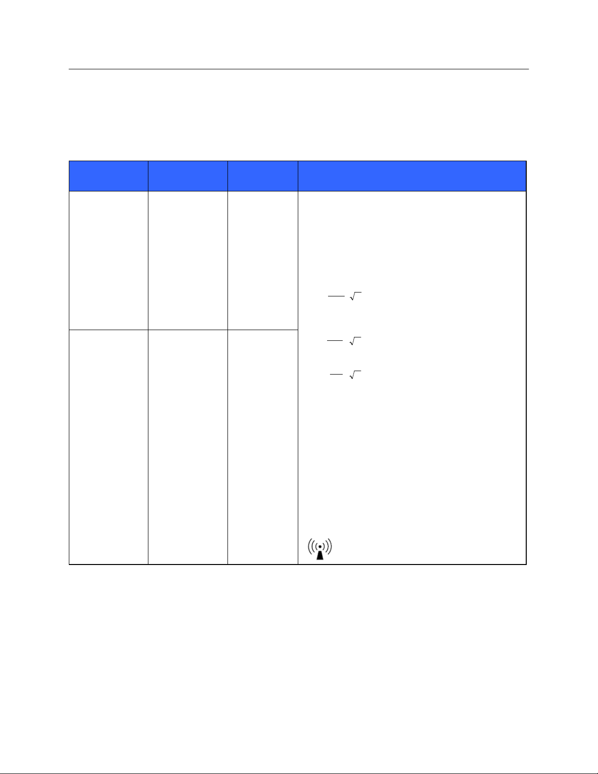
Immunity Test
IEC 60601 Test
Level
Compliance
Level
Electromagnetic Environment: Guidance
Conducted RF
EN 61000-4-6
3 Vrms
150 kHz to
80 MHz
3 Vrms
150 kHz to
80 MHz
Portable and mobile RF communications equipment
should be used no closer to any part of the equipment,
including cables, than the recommended separation
distance calculated from the equation applicable to the
frequency of the transmitter.
Recommended separation distance
d
3.5
P
3Vrms
d
3.5
P
80 MHz to 800 MHz
3V / m
d
7
P
800 MHz to 2.5 GHz
3V / m
Where P is the maximum output power rating of the
transmitter in watts (W) according to the transmitter
manufacturer and d is the recommended separation
distance in meters (m).
Field strengths from fixed RF transmitters, as
determined by an electromagnetic site surveya, should
be less than the compliance level in each frequency
rangeb.
Interference may occur in the vicinity of equipment
marked with the following symbol:
Radiated RF
IEC 61000-4-3
3 V/m
80 MHz to
2.5 GHz
3 V/m
80 MHz to
2.5 GHz
Guidance and Manufacturer’s Declaration: Electromagnetic Immunity
The equipment is intended for use in the electromagnetic environment specified in the table below. The customer or
the user of the equipment should ensure that it is used in such an environment.
a. Field strengths from fixed transmitters, such as base stations for radio (cellular/cordless) telephones and land mobile radios,
amateur radios, AM and FM radio broadcast, and TV broadcast cannot be predicted theoretically with accuracy. To assess
the electromagnetic environment due to fixed RF transmitters, an electromagnetic site survey should be considered. If the
measured field strength in the location in which the equipment is used exceeds the applicable RF compliance level above, the
equipment should be observed to verify normal operation. If abnormal performance is observed, additional measures may be
necessary, such as reorienting or relocating the equipment.
b. Over the frequency range 150 kHz to 80 MHz, field strengths should be less than [3] V/m.
15

INTRODUCTION
Rated Maximum Output Power
of Transmitter W
Separation Distance According to Frequency of Transmitter (m)
150 KHz to 800 MHz
800 MHz to 2.5 GHz
d 1.2 P
d 2.3 P
0.01
0.1 m
0.2 m
0.1
0.4 m
0.7 m
1
1.2 m
2.3 m
10
4.0 m
7.0 m
100
12.0 m
23.0 m
Recommended Separation Distances Between Portable and Mobile RF
Communications Equipment and the Equipment
The equipment is intended for use in the electromagnetic environment in which radiated RF disturbances are
controlled. The customer or the user of the equipment can help to prevent electromagnetic interference by
maintaining a minimum distance between portable and mobile RF communications equipment (transmitters) and the
equipment as recommended in the table below, according to the maximum output power of the communications
equipment.
For transmitters rated at a maximum output power not listed above, the recommended separation distance d in
meters (m) can be estimated using the equation applicable to the frequency of the transmitter, where P is the
maximum output power rating of the transmitter in watts (W) according to the transmitter manufacturer.
NOTE 1: At 800 MHz, the separation distance for the higher frequency range applies.
NOTE 2: These guidelines may not apply in all situations. Electromagnetic propagation is affected by the
absorption and reflection from structures, objects, and people.
16
 Loading...