

Mortara ELI 350 Service manual

REF 9516-171-50-ENG Rev D1
ELI 350
12-LEAD RESTING ELECTROCARDIOGRAPH
SERVICE MANUAL
Manufactured by Mortara Instrument, Inc., Milwaukee, Wisconsin U.S.A.
CAUTION: Federal law restricts this device to sale by or on the order of a physician

Copyright © 2007-2011
by Mortara Instrument, Inc.
7865 N. 86th Street
Milwaukee, Wisconsin 53224
This document contains confidential information that belongs to Mortara Instrument, Inc. No part of this document
may be transmitted, reproduced, used, or disclosed outside of the receiving organization without the express written
consent of Mortara Instrument, Inc. Mortara is a registered trademark of Mortara Instrument, Inc.

TECHNICAL SUPPORT AND SERVICE
Headquarters
Mortara Instrument, Inc.
7865 North 86th Street
Milwaukee, WI 53224
U.S.A.
Tel: 414.354.1600
Tel: 800.231.7437
Fax: 414.354.4760
Internet: http://www.mortara.com
European Union
Representative
Mortara Rangoni Europe, Srl
(European Headquarters)
Via Cimarosa 103/105
40033 Casalecchio di Reno (BO)
Italy
Tel: +39.051.298.7811
Fax: +39.051.613.3582
Service/Technical
Support Group
Mortara Instrument, Inc.
7865 North 86th Street
Milwaukee, WI 53224
U.S.A.
Tel: 414.354.1600
Service: 888.MORTARA
(888.667.8272)
Fax: 414.354.4760
E-mail: techsupport@mortara.com
24-hour Technical Support
Same-day Shipment of Replacement Parts
Biomedical Training Classes
Extended Warranties/Service Contracts
Sales Support/
Supplies & Accessories
Mortara Instrument, Inc.
7865 North 86th Street
Milwaukee, WI 53224
U.S.A.
Tel: 414.354.1600
Fax: 414.354.4760
E-mail: sales@mortara.com
Mortara Instrument Germany
Kaninenberghöhe 50
45136 Essen
Germany
Tel: +49.201.18 55 69 70
Fax: +49.201.18 55 69 77
Mortara Instrument Netherlands
Postbus 324
5680 AH Best
Randweg 4
5683 CL Best
Netherlands
Tel: +31.499.377310
Fax: +31.499.377908
Mortara Instrument Australia
PO Box 7568
Unit 11, 7 Inglewood Place
Baulkham Hills NSW 2153
Australia
Tel: +61 2 8824 5499
Fax: +61 2 8814 5399

Table of Contents:
1 General
User Safety Information ………………………………………………………………… 1-1
Symbol Delineation ...…………………………………………………………………… 1-2
2 Maintenance and Cleaning
Preventive Maintenance Procedure……………………………………………………. 2-1
Device Cleaning and Disinfecting………………… ……………………………………. 2-4
Safety Testing…….….…………………………………………………………………… 2-5
3 Assembly/Disassembly of Unit
Special Instructions and Cautions ………………………………………………… …. 3-1
Base Unit assembly / disassembly ………...…………………………………………. 3-2
Base assembly parts list ………...……………………………………………………. 3-36
LCD assembly / disassembly ………...………………………………… ……………. 3-37
LCD assembly parts list ………...........………………………………………………. 3-53
Writer assembly / disassembly ………....……………………………………………. 3-54
Writer assembly parts list ………...……………..……………………………………. 3-66
4 Troubleshooting and Testing
ELI350 Troubleshooting ………………………………………………………………… 4-1
ELI350 Testing ………………………..………………………… ……………………… 4-3
Cue Sensor Adjustment ………………………………………………………………. 4-4
Modem Country Codes ..……………………………………………………………… 4-8
Safety Tests ………………………………………………………… …………………… 4-9
5 Options & Upgrades
Upgrade Options ………………………………………………………………………… 5-1
viii

____________________________________________________________________________Section 1
1 General
Service Manual Purpose
The purpose of this manual is to supply information to service personnel so they can maintain the ELI 350
Electrocardiograph at the assembly and subassembly level. Although the manual includes parts lists,
mechanical assembly parts, and printed circuit board information, it is intended to function primarily as a
guide to preventative and corrective maintenance and electrical repairs considered field repairable.
User Safety Information
Periodic Safety Inspections
Follow the recommended maintenance schedule. Inspect the power cord and transmission cables
periodically for fraying or other damage and replace as needed. Broken or frayed wires may cause
interference or loss of signal. Pay particular attention to points where wires enter connectors.
Proper Power Cord
Use only the power cord specified for the equipment. This product requires a three-wire, (18 gauge, SJTgrade) power cord, which is supplied with a three-terminal, polarized plug (hospital grade) for connection
to the power source and protective ground. Use only a power outlet with a protective ground outlet. An
interruption of the grounding connection could cause an electrical shock hazard.
Proper Fuse
Use only the fuse specified for the equipment (identical in type, voltage and current rating). Substituting a
different fuse type could cause a fire hazard. Always make sure fuses have been installed before
operating the unit.
Do Not Operate in Explosive Atmospheres
Do not operate the ELI 350 in the presence of flammable gasses or anesthetics; this environment could
cause an explosion. Refer to Operator's Manual Safety Information: Warning(s) and Caution(s).
Use Only Safe Methods of Interconnection
To prevent electrical shock from the product when it is connected to other electrical equipment, proper
grounding is essential. Refer to Operator's Manual Safety Information: Warning(s) Peripheral equipment.
Do Not Mount Product above Patient
Do not mount or place the product where it could fall on a patient or where it could be accidentally
knocked off a shelf or other mounting arrangement.
Recommended Accessories
For the patient's safety and optimum equipment performance, use only the accessories specified by
Mortara Instrument, Inc.
1-1

ELI 350__________________________________________________________________________
Sterilizing this Product
Do not sterilize this product or any accessories unless specifically directed by the manufacturer.
Sterilization and sterilization environments can seriously damage many components and
accessories.
Liquid Spills
Do not set beverages or other liquids on or near the ELI 350, and/or optional equipment.
Product Information
Refer to the User’s Manual
Manual Symbol Delineation
Electrostatic sensitive devices
Caution or Special Instructions
1-2

____________________________________________________________________________Section 2
2 Maintenance and Cleaning
Preventive Maintenance
Preventive maintenance is recommended to be performed on the ELI350 cardiograph once every 12 months.
A preventive maintenance report to document the maintenance activity performed is located at the end of this
section of the manual.
Warning: Preventive maintenance is to be performed by Mortara authorized service
personnel only.
Maintenance Procedure:
• Turn on the cardiograph and print the unit configuration information from the “System Settings” page.
• Remove the upper housing per section 3 of this manual.
• Remove the four (4) screws from the writer assembly, without disconnecting the cables, to perform the
complete visual inspection below.
• Perform a visual inspection of the following items:
o Enclosure/Housing – Look for damage or cracks in the external housing or enclosure that could
possibly expose the device to the introduction of foreign objects or fluids. Attention should also be
paid to areas that could expose an operator or patient to internal circuitry of the device.
o Contamination – Look for any contamination that may have occurred over time that could not be
seen with the housing in place.
Fluid damage (perhaps caused during device cleaning)
Debris on or behind display shield
Battery leakage (lithium and main battery)
o Internal Cabling – Look for cracked, pinched or partially disconnected cable connections.
o Fuse Ratings – Verify the battery and AC line fuses match the device labeling.
o Markings and Labeling – Verify all labels and device markings are clearly visible and legible to
the device user and have not been worn off or rendered unreadable through the use of harsh
cleaning agents.
o Integrity of Mechanical Parts – Verify the following items are properly secured to the device and
have not become loose or damaged through usage over time.
AC Inlet
Patient Input Connector
Communication ports and antenna
Writer mechanics/latching mechanism
LCD Assembly
2-1

ELI 350__________________________________________________________________________
• Power Testing
o Note battery age (if possible)
This information can be found on the “date code” sticker on the battery (use the earliest date
crossed out on the label); or on a sticker located on the bottom of the unit.
Based upon customer usage, and the age of the main battery, replace as needed and place a sticker
on the bottom of the unit to identify when the battery was replaced.
If the internal lithium battery is older than 5 years it should be replaced and a sticker should be placed
on the bottom of the unit to identify when the lithium battery was replaced.
Ensure the battery is fully charged before performing the battery tests; the test limits are based on a
fully charged battery.
Disconnect the AC power cord to begin this section of tests.
With the upper housing off of the unit, disconnect the battery cable from the positive terminal.
o Battery Open Circuit – Measure the open circuit battery voltage using a volt meter across the
battery terminals, the meter should read greater than 12.5vdc.
o Battery w/Load – Measure the battery voltage using a volt meter with a power resistor load
(10ohm, 20watt) across the battery terminals. After loading the battery for approximately 5
seconds, the meter should read greater than 11.7vdc.
o Off Current – Connect a current meter in line with the positive battery terminal to the
motherboard. With the unit in the “off” state the meter should read less than 450 micro amps.
o On Current – Set the current meter to a setting greater than 5 amps, and turn the unit on. Once
the unit powers up to the main menu, the current should read less than 2.7 amps.
o AC Charging Current – Insert the AC power cord and verify that the current draw from the battery
reverses polarity (starts to charge the battery) and the value starts decreasing in magnitude as
time increases.
o Battery Charger Output Voltage – Disconnect the current meter and measure the battery charger
output voltage between the disconnected positive battery cable and the negative battery terminal.
It should read between 13.0 and 14.0vdc.
Reconnect the battery cable to the positive terminal and verify all other internal cables are properly
connected. Install the writer assembly screws and the upper housing on the cardiograph.
2-2

____________________________________________________________________________Section 2
• Functional Testing
o AC/DC LED
Connect a power source to the AC inlet of the UUT. Verify the AC LED on the keyboard
illuminates continuous. With the display in the upright position, turn the unit on. The
BATTERY LED will illuminate continuously if the battery is charging, it will turn off when
the battery is fully charged or when the display is completely lowered.
o LCD/Tilt Switch
Verify the LCD backlight is on and there are no flickering or missing lines/pixels.
Slowly lower the LCD, verify the backlight turns off before or it is completely lowered.
Raise the LCD and verify the backlight turns back on.
o Writer
Open and close the writer drawer. Verify smooth operation of the drawer. Verify that the
drawer unlatches without sticking. Verify that the drawer latches completely.
From the main screen, click on SETTINGS, enter PASSWORD “Print test” and then
press the Enter key. Verify that a test page is printed and the writer stops on the cue
mark. The perforation on the paper should line up with the tear edge on the UUT.
Assure there are no gaps in the print and darkness is uniform across the entire page.
Verify no gear skipping and proper paper tracking as the writer prints (you might need to
print 3 or more pages to verify this).
o ECG & Keyboard Matrix
Using a Mortara 10-lead patient cable, connect an ECG simulator to the UUT. Set the
simulator to an appropriate heart rate and amplitude to enable visual confirmation of the
correctness of the ECG printout (comparison to a sample printout from a “known good”
device is recommended). Press the AUTO key to capture an ECG. Enter Last Name
“PARCFL8”, click on OK to continue and then print the ECG.
NOTE: “PARCFL8” ensures the keyboard matrix is fully tested. Verify there is an audible
beep with each key press.
Verify that 12 ECG traces print with the correct heart rate, amplitude and morphology,
then assess the overall print out quality (ensure there is uniform darkness across entire
printout).
o ECG Noise Test
Connect a Shorting Block (TF-0063) or equivalent to the UUT and set the ECG gain to
20mm/mV. Print a Rhythm strip (approx. 1 page). Verify that no channels have more
than 0.5mm of baseline noise.
o Communication options
Transmit a test ECG record to a compatible receiving device for all of the applicable
communication options enabled below:
• Modem
• LAN
• WLAN
2-3

ELI 350__________________________________________________________________________
Device Cleaning & Disinfecting
Warning:
• Use of non-recommended cleaning agents or practices could cause damage to the device or possible
compromising of the electrical isolation of the device.
• Makes sure all cables and accessories are disconnected from the device prior to performing cleaning
process.
• Do not immerse the device in liquid.
• Do not use organic solvents, ammonia-based solutions, or abrasive cleaning agents that may damage
equipment surfaces.
• Do not use excessive amounts of liquid during cleaning or disinfecting of the device, as these fluids could
enter the device housing and cause damage to the device.
Recommended Supplies:
• Clean lint free cloth
• Mild detergent
• Luke warm water
• 10% Household bleach and water solution (Sodium Hypochlorite solution consisting of a minimum 1:500
dilution and maximum of 1:10 dilution for disinfecting use only)
• Isopropyl alcohol or alcohol wipe
Device Cleaning:
Disconnect the AC power cord from the device. Clean the exterior surface of the device with a damp (not wet),
soft, lint-free cloth using a solution of mild detergent diluted in luke warm water. After cleaning, thoroughly dry off
the device with a clean, soft cloth or paper towel.
Open the writer door and wipe the thermal print head clean with a moist alcohol pad and allow it to air dry.
Device Disinfecting:
Clean the device per the instructions defined above, then wipe the exterior of the device with a damp (not wet),
soft, lint-free cloth using a solution of 10% bleach and water. Allow the device to air dry after disinfecting before
returning to use.
2-4

____________________________________________________________________________Section 2
Safety Testing
The following safety tests should be performed in accordance with IEC 60601 or IEC 62353 standards and all
local regulatory requirements:
• Earth Leakage
• Enclosure Leakage
• Patient Leakage
• Patient Leakage Type-F
• Patient Auxiliary Current
2-5

Mortara Instrument, Inc. Phone (414) 354-1600
7865 N. 86
Milwaukee, WI. 53224
th
Street Fax (414) 354-4760
Mortara Instrument Inc.
ELI350 Preventive Maintenance Report
Unit Serial #: _________________________________________
□ Print device configuration
□ Remove upper housing and writer assembly
□ Perform Visual Inspection
□ Enclosure/Housing
□ Contamination
□ Cabling
□ Fuse Ratings
□ Markings and Labeling
□ Integrity of Mechanically Parts
□ Power Testing
□ Note Battery Age
(Based upon customer usage and age of main battery, replace as needed)
□ Battery Open Circuit Voltage _______ VDC
□ Battery Load Test _______ VDC
□ OFF Current _______ uA
□ On Current _______ A
□ AC Charging Current
□ AC Charging Voltage _______ VDC
□ Check age of Lithium Battery (replace if older than 5 years)
□ Verify all power cables are properly reconnected and reassemble unit
□ Functional testing
□ AC/DC LED Operational
□ Display Functionality
□ Writer Test
□ ECG & Keyboard Matrix Testing
□ ECG Noise Test
□ Communication Options
□ Device Cleaning
□ Safety Testing PASS / FAIL (circle)
□ Earth Leakage
□ Enclosure Leakage
□ Patient Leakage
□ Patient Leakage Type-F
□ Patient Auxiliary Current
Technician or Field Service Engineer: ____________________________ Date: _____/_____/_____
(If Possible) _____/_____ (week/year)
(reverses polarity and decreases in magnitude)

____________________________________________________________________________Section 3
3 Assembly / Disassembly
Special Instructions
The following section defines the assembly of the ELI350 electrocardiograph;
disassembly should be performed by reversing the assembly process per these
instructions.
This assembly procedure describes the use of Vibra-Tite on some threaded parts. The
Vibra-Tite must dry for a minimum of 10 minutes before assembly. The Vibra-Tite may
be applied to the threaded pieces ahead of time and allowed to dry. This way the parts
will be available for assembly when needed. If the parts already have Vibra-Tite, this
process can be skipped.
Before applying all adhesive backed materials, clean surface with alcohol to make sure
it is clean and oil free.
Torque specifications for all fastening devices shall be 3.5-4.0 lbs-in, unless otherwise
noted.
Note: Item numbers refer to the parts lists at the end of each assembly section.
Cautions
CAUTION: Risk of Explosion - DO NOT SHORT Battery Terminals. Leave protective
covers on the terminals until assembly into the base unit.
CAUTION: Risk of Shock – Line voltage may be present on the Motherboard. DO
NOT touch components on the motherboard when performing confidence testing at the
sub-assembly level.
Caution: Risk of injury – The ELI 350 weighs approximately 30 lbs. Use proper lifting
techniques.
ATTENTION: The ELI 350 contains ESD Sensitive sub-assemblies. Observe ESD
handling techniques when working with electronic assemblies.
ATTENTION: Pay particular attention to the positioning of the transformer wires on the
motherboard to ensure the wires are not pinched during the assembly of the
motherboard to the lower housing.
ATTENTION: Prevent pinching of all cables and harnesses by inspecting for proper
routing during final assembly.
3-1
ELI 350__________________________________________________________________________
LCD Display Sub-Assembly
Instructions for the assembly of the LCD display begin on page 3-35.
Writer Sub-Assembly
Instructions for the assembly of the 8” thermal writer begin on page 3-52.
Base Assembly
Note: Installation of optional communication hardware (Ref sections: Modem
Option, WLAN Option) requires soldering components to the motherboard prior
to installing the motherboard into the Base Assembly.
Note: It is recommended to apply all the applicable labeling (Ref section: ELI
350 Labeling) during the Base Assembly process.
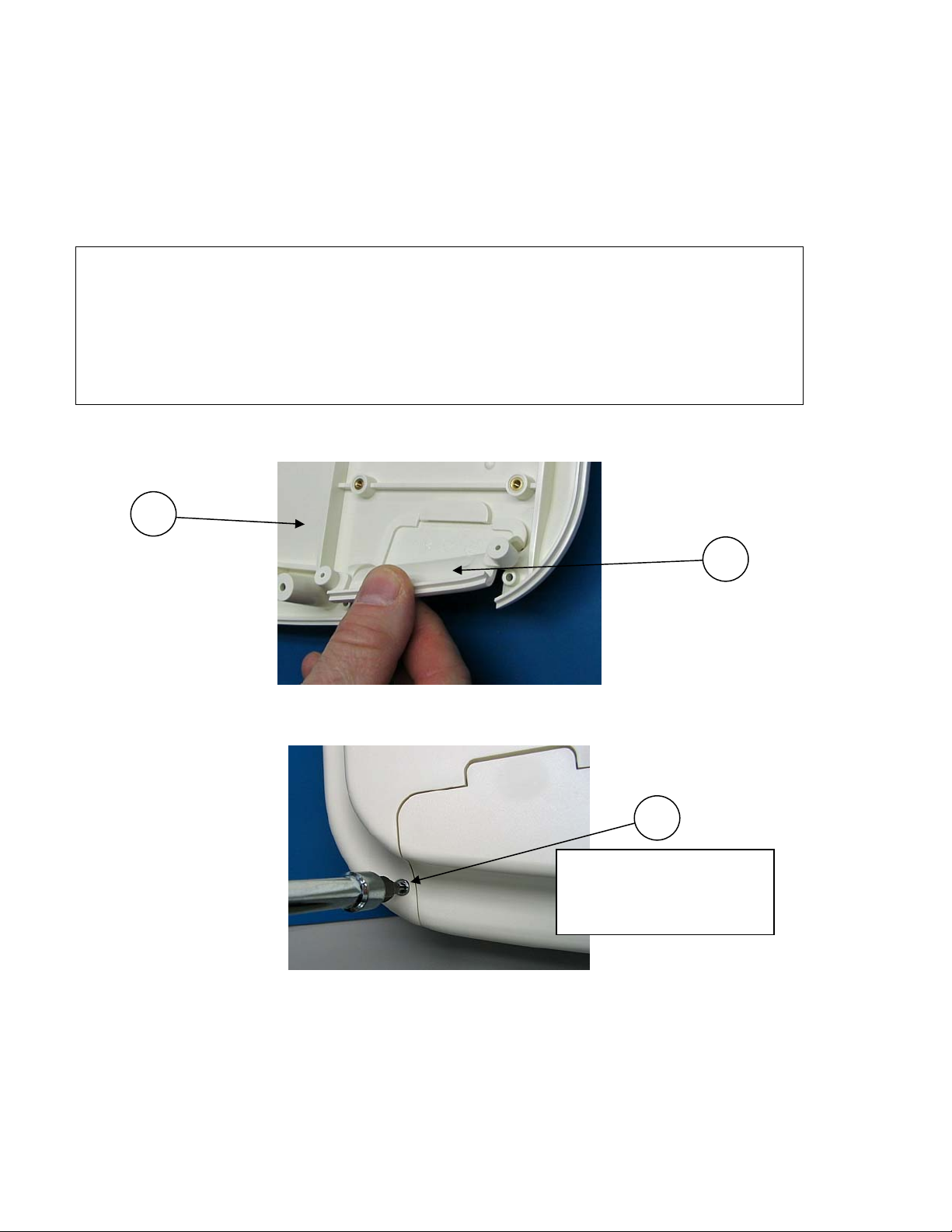
Insert the blank bulkhead Front Closure Plate (Item 6) in to the Lower Housing (Item
3) and snap in place.
3
6
Flip the Lower Housing over and secure the Front Closure Plate to the Lower Housing
using 2 screws (Item 30). Use a T9 bit. Torque Spec: Hand Tighten Only
30
2 Plcs –
Torque Spec: Hand
Tighten Only
3-2
____________________________________________________________________________Section 3
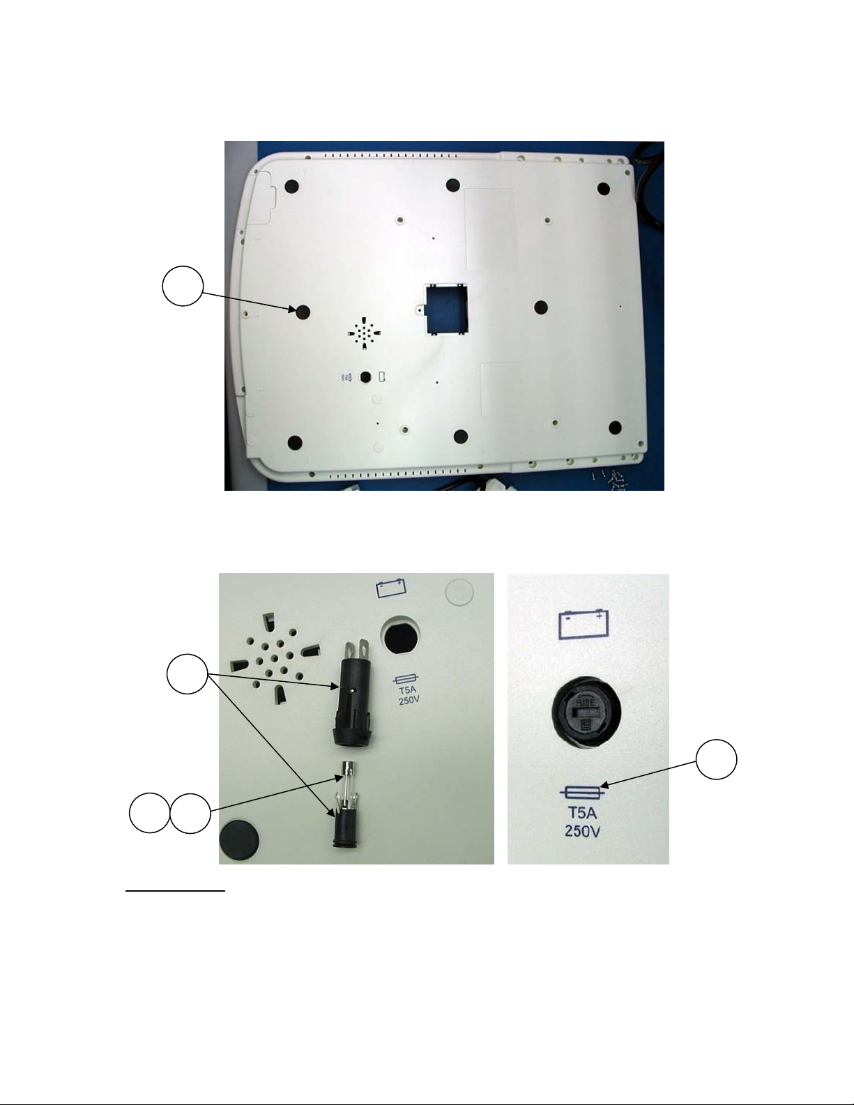
Apply the Rubber Feet (Item 22, 8 Plcs) to the Lower Housing in the recessed areas
provided.
22
8 Plcs
Insert the Fuse Holder Assembly (Item 17) and Fuse (Item 16 or 32 {see note below})
into the Lower Housing.
Ensure the Fuse Holder insert is fully clockwise and locked in place.
17
35
16
32
IMPORTANT
– The battery fuse on the ELI350 unit is dependant upon the item
number of the unit’s motherboard. Units manufactured with the older motherboard
(Item #26025-076-51) use a 5A fuse; and those manufactured with the newer
motherboard (Item # 26025-076-52) use an 8A fuse. Fuse labeling shown above is for
the 5A fuse application; fuse rating labels (Item # 35) are available to properly label
the unit chassis if a fuse rating change is required, due to a motherboard service
replacement.
3-3
ELI 350__________________________________________________________________________
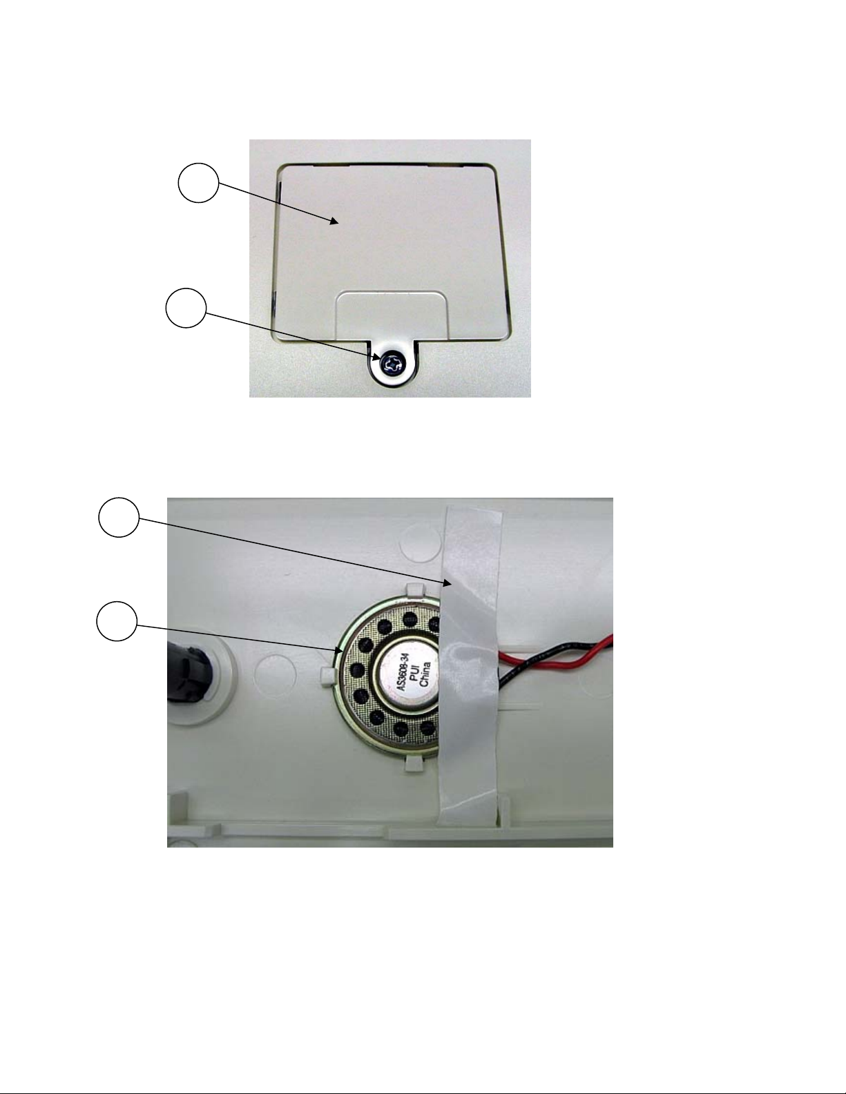
Insert the SIM Card Access panel (Item 27) into the Lower Housing and secure with
screw (Item 18).
27
18
Flip the Lower Housing back onto the rubber feet. Insert the Speaker (Item 12) as
shown. Remove the paper backing from one side only and secure the Speaker to the
Lower Housing with a piece of Foam Tape (Item 23).
23
12
3-4

____________________________________________________________________________Section 3
Install Front End PCB (Item 14) into Lower Housing and secure in place with 2 screws
(Item 19) and 2 screws (Item 20).
14
20
19
14a
If the 10K+ AUXILIARY PCB ASSY (Item 14a) is needed for the 15 lead option, install
the 10K+ AUXILIARY PCB ASSY onto Front End PCB (Item 14) prior to installation of
Front End PCB (Item 14) Assy.
*Note – This option can only be installed on the -52 and -53 motherboards; the
hardware on the -51 motherboard does not support this option.
3-5
ELI 350__________________________________________________________________________
Communication Option Installation
Installation of optional communication hardware requires soldering components
to the motherboard prior to installing the motherboard into the Base Assembly.
Additional items will also need to be installed depending on the required option
Ref sections: Modem Option, WLAN Option for installation instructions.
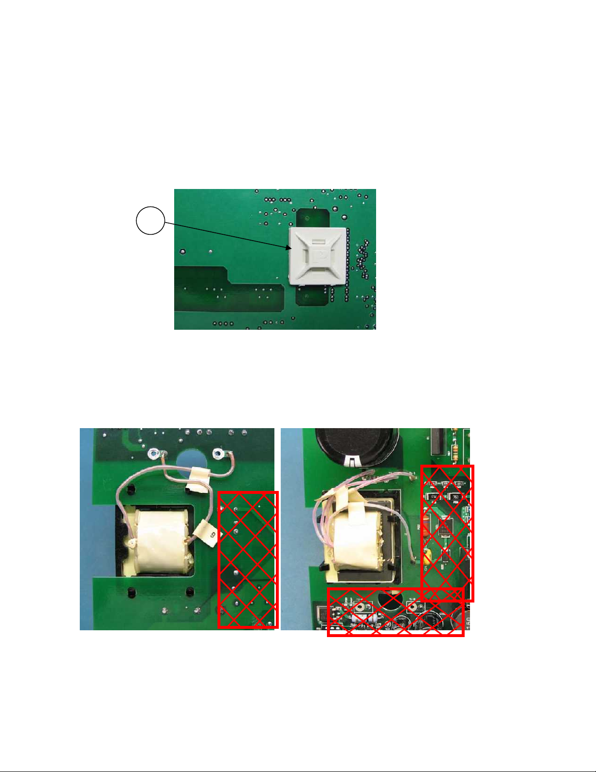
Apply Cable Tie Mount (Item 29) to bottom side of ELI 350 Motherboard under the
LCD signal cable connector location as shown.
29
CAUTION: Motherboards labeled as item # 26025-076-51 (original PCB layout) utilize the
transformer shown below. The transformer wires MUST be positioned away from the
secondary circuit and any mounting bosses to ensure wires are not pinched during
assembly. Motherboards labeled as item # 26025-076-52 utilize a different transformer
design that eliminates the possibility of this potential hazard.
Bottom View Top View
3-6
____________________________________________________________________________Section 3
Install the ELI 350 Motherboard (Item 15) into the Lower Housing. Secure in place
with 4 screws (Item 19) and 4 screws (Item 20).
20
4 Plcs
19
4 Plcs
20
19
19 19
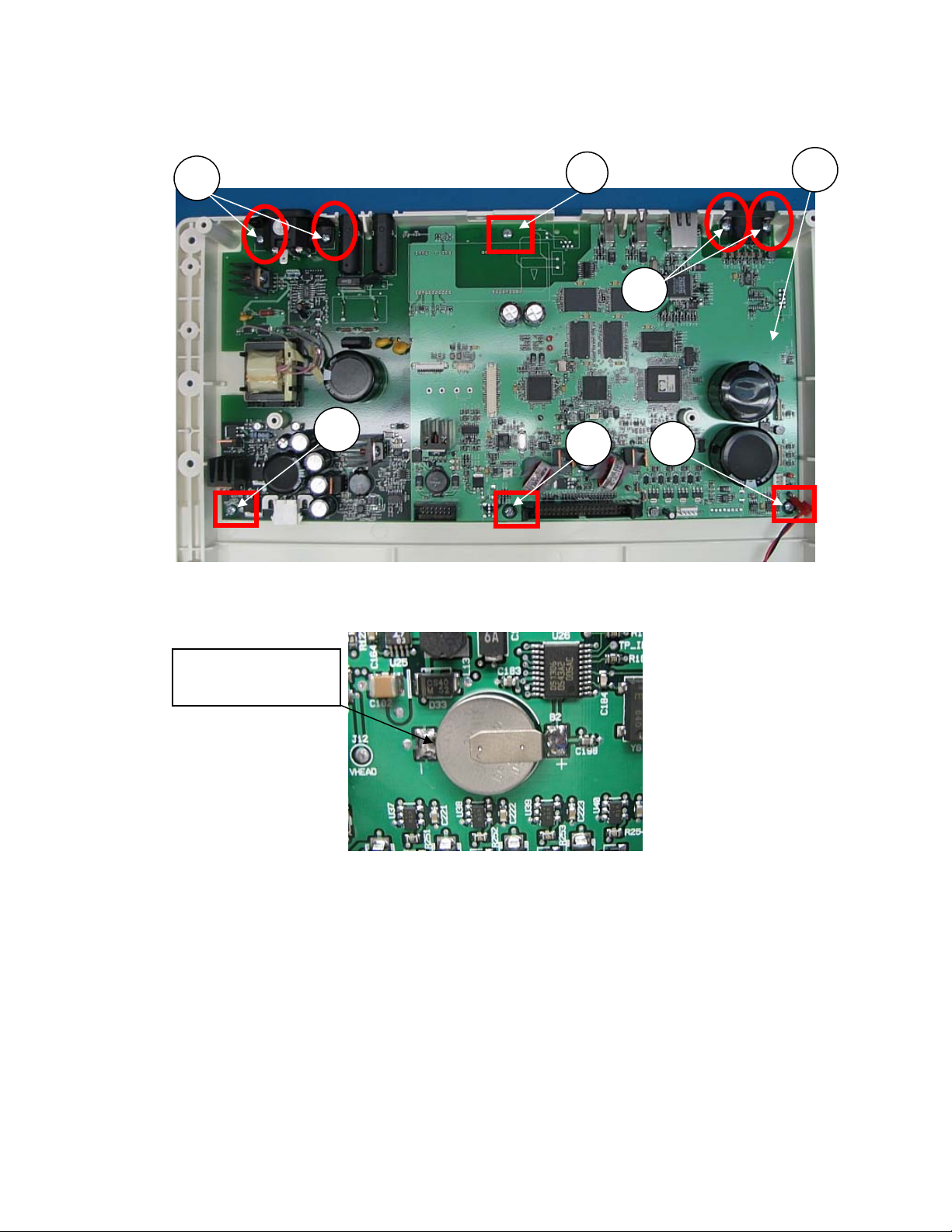
Ensure Lithium Battery is properly soldered to the Motherboard as shown.
15
Battery –
Positive Side Up
3-7
ELI 350__________________________________________________________________________
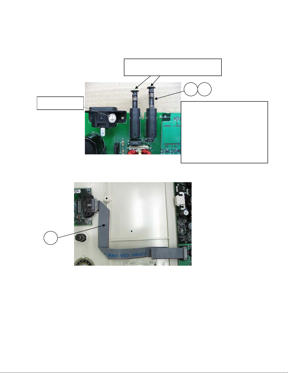
Ensure Power Line Fuses are installed and properly inserted into holder. Rotate the
insert fully clockwise to lock the fuse in place.
Ensure Ground Label is applied to any of the flat surfaces of the AC Power Inlet
connector.
Rotate insert fully clockwise
Fuses
33 34
Ground Label
AC Line fuses are dependant upon
the item number of the unit’s display.
Units manufactured with the older
display (Item # 5400-016) use T1A
fuses; and those manufactured with
the newer display (Item # 5400-017)
use T2A fuses. Fuse rating labels for
the exterior housing (Item # 35) are
available for service use when
modifying original unit configurations.
Install the Front End Ribbon Cable (Item 11). Connect each end to the applicable
PCB assembly and route the cable as shown.
11
3-8
____________________________________________________________________________Section 3
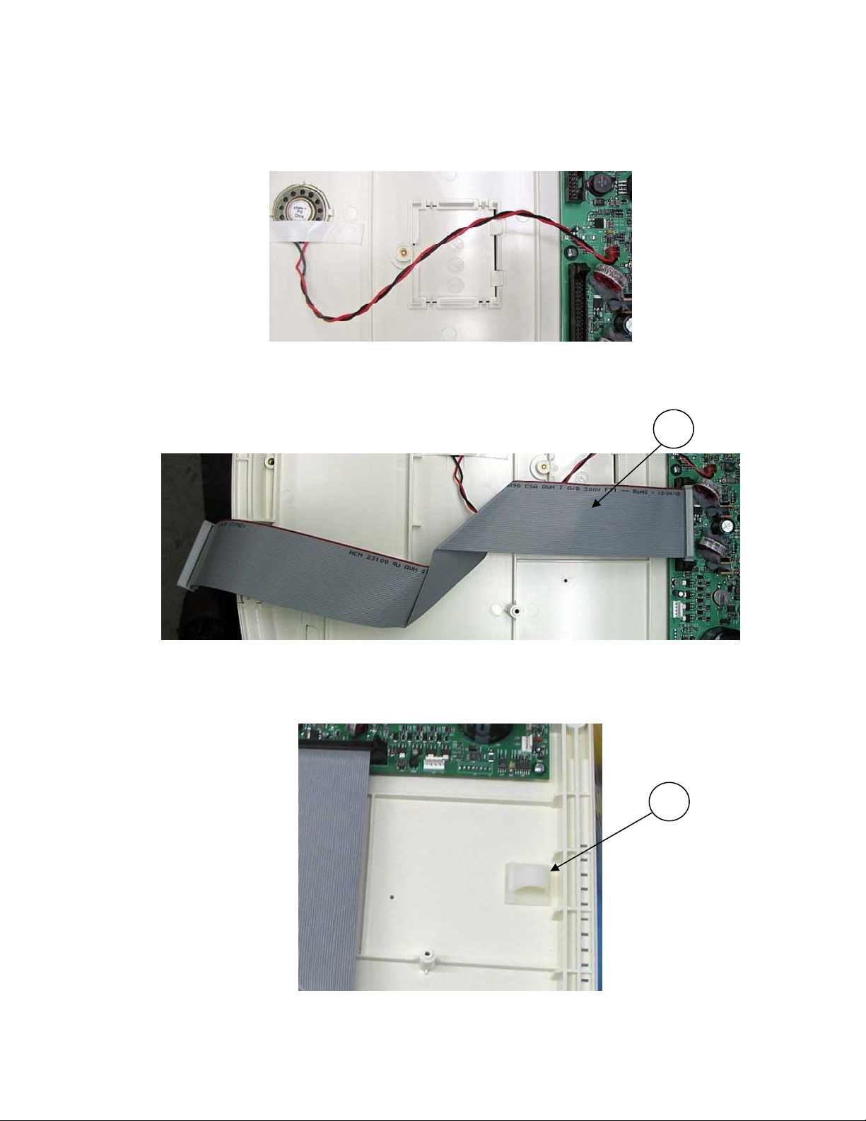
Connect the speaker to the Motherboard as shown.
Note: The cable will need to be routed away from the access cover if an optional GSM
(Future) module is installed
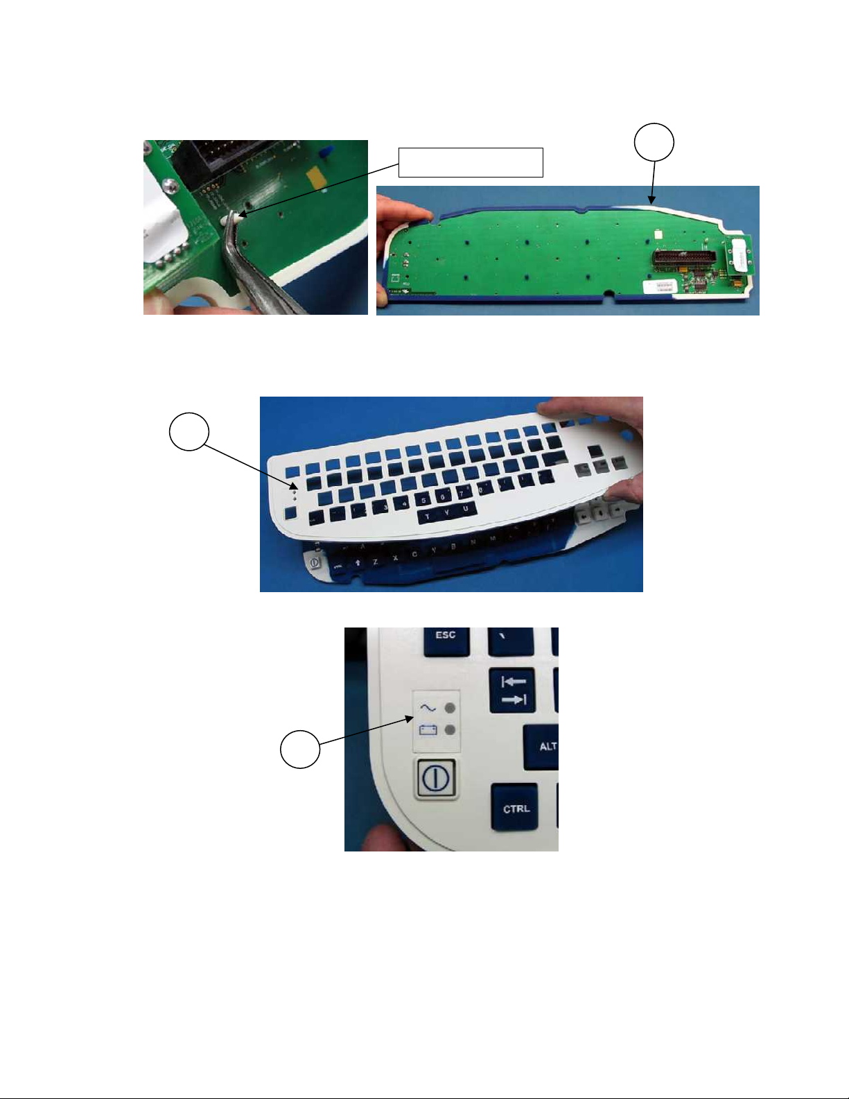
Connect the Keyboard Ribbon Cable (Item 36) the Motherboard as shown. Ensure the
short end on the Z-fold is the end connected to the Motherboard.
36
Install the cable retention clip (Item 26) inside the lower housing along the right side
as shown. This will be used for routing the writer cables later in the assembly.
26
3-9
ELI 350__________________________________________________________________________
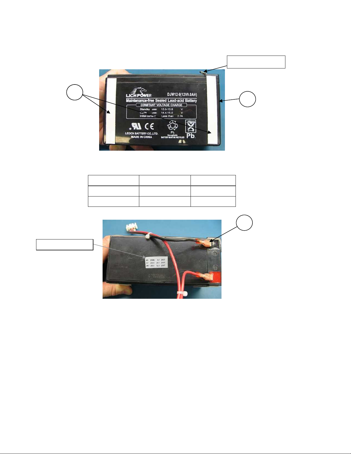
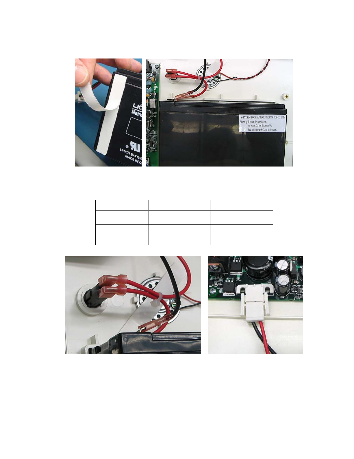
Apply 2 pieces of double sided tape (Item 23) to the Battery (Item 1), as shown. Note
that the battery terminals are to the operator’s right in this view.
23 23
Connect the Battery Cable (Item 13) to the battery as shown
Wire Color Termination Type Location
Red (Short Wire) Fast-on Straight (+) Battery Tab
Black Fast-on Straight (-) Battery Tab
Battery Terminals
1
13
Date Code Label
3-10
____________________________________________________________________________Section 3
Remove paper backing from double sided tape and install battery into the lower
housing as shown. Note the orientation of the battery terminals to the fuse holder.
Connect battery cable to the fuse holder and Motherboard as shown.
Wire Color Termination Type Location
Red (Short Wire) Fast-on Right Angle Fuse Holder Tab
Closest to battery
Red (Long Wire) Fast-on Right Angle Fuse Holder Tab
Furthest from battery
Red/Black Two pin connector Mother Board P16
3-11

ELI 350__________________________________________________________________________
Top Cover Keyboard Assembly
Note: Item numbers in this section refer to the parts on the applicable keyboard
assembly.
For all keyboard options: Apply the LCD Bumpers (Item 9, 2 Plcs) to the Top Housing
(Item 2), as shown.
9
2
Option: Click Knob keyboard Assembly
Ensure Click Knob PCB is soldered to the keyboard PCB (Item 37) as shown.
Click Knob PCB
37
3-12
____________________________________________________________________________Section 3
Apply the Elastomeric Keypad (Item 38) to the Keyboard PCB. Pull all alignment tabs
(10 Plcs) completely through the keyboard PCB.
38
Alignment Tab(s)
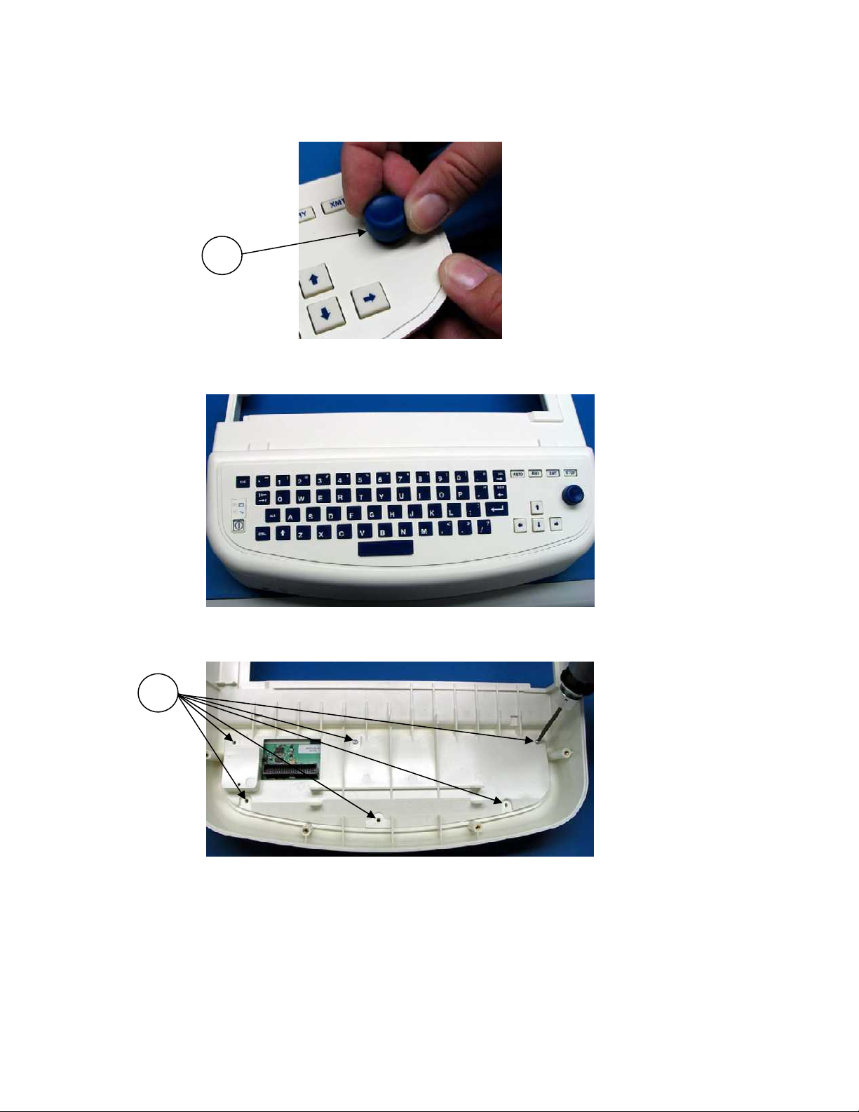
Apply Keyboard Bezel (Item 39) over the Elastomeric Keypad as shown. Ensure all keys
extend through the applicable opening.
39
Apply the Battery / Power Label (Item 40) to the Keyboard Bezel.
40
3-13
ELI 350__________________________________________________________________________
Apply the Click Knob (Item 41) to the keyboard assembly as shown. Ensure the knob is
fully seated to the shaft of the assembly.
41
Apply the Keyboard Bezel Assembly to the Top Housing (part of the core BOM) as
shown. Ensure the Bezel is centered in the opening.
Flip the assembly over and secure the keyboard bezel to the top cover with 6 screws
(Item 20).
20
3-14
____________________________________________________________________________Section 3
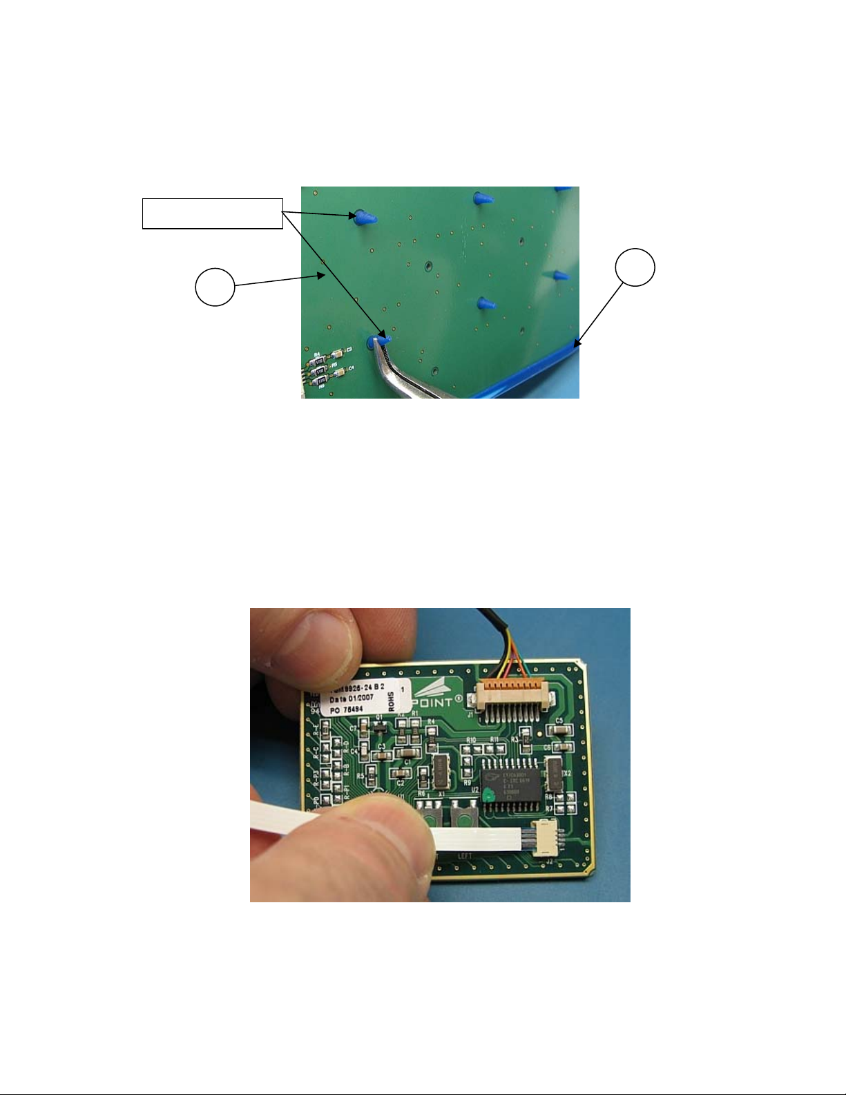
Option: Touch Pad keyboard Assembly
Apply the Elastomeric Keypad (Item 38) to the Keyboard PCB (Item 37). Pull all
alignment tabs (10 Plcs) completely through the Keyboard PCB.
Alignment Tab(s)
38
37
Connect USB cable to Touch Pad, as shown below.
Insert the flex circuit to the 4 pin connector located on the Touchpad electronic
assembly, as shown.
Note: The flex circuit is oriented with the contacts up.
Note: The flex circuit is retained by the compression fit connector. DO NOT crease the
flex circuit when inserting it into the connector.
3-15
 Loading...