

Mortara ELI 250, ELI 210 User manual

REF: 9516-163-50-ENG Rev: B1
ELI 250 / ELI 210 Service Manual
Manufactured by Mortara Instrument, Inc. Milwaukee U.S.A.
CAUTION: Use of this service manual is intended for qualified service personnel only.
CAUTION: Federal law restricts this device for sale to or on the order of a physician.

Copyright© 2004
by Mortara Instrument, Inc.
7865 N. 86th Street
Milwaukee, Wisconsin 53224
This document contains confidential information that belongs to Mortara Instrument, Inc. No part of this document may be transmitted,
reproduced, used, or disclosed outside of the receiving organization without the express written consent of Mortara Instrument, Inc.
Mortara is a registered trademark of Mortara Instrument, Inc

TECHNICAL SUPPORT AND SERVICE
Headquarters
Mortara Instrument, Inc.
7865 North 86th Street
Milwaukee, WI 53224
Tel: 414.354.1600
Tel: 800.231.7437
Fax: 414.354.4760
Internet: http://www.mortara.com
Europe Economic
Community Representative
Mortara Rangoni Europe, Srl
(European Headquarters, Italy)
Via Oradour 7
40016 S. Giorgio di Piano, BO
Tel: +39.051.6654311
Fax: +39.051.6651012
Service/Technical
Support Group
Mortara Instrument, Inc.
7865 North 86th Street
Milwaukee, WI 53224
Tel: 414.354.1600
Service: 888.MORTARA
(888.667.8272)
Fax: 414.354.4760
E-mail: techsupport@mortara.com
24 Hour Technical Support
Same Day Shipment of Replacement Parts
Biomedical Training Classes
Extended Warranties/Service Contracts
Sales Support/
Supplies & Accessories
Mortara Instrument, Inc.
7865 North 86th Street
Milwaukee, WI 53224
Tel: 414.354.1600
Fax: 414.354.4760
E-mail: sales@mortara.com
Mortara Instrument GmbH
(Germany)
Henricistr. 124
45136 Essen
Tel: +49.201.268311
Fax: +49.201.268313
Mortara Instrument B.V.
(The Netherlands)
H. Dunantplein 6
3731 CL De Bilt
Postbus 131
3720 AC Bilthoven
Tel: +31.30.2205050
Fax: +31.30.2201531
i

Notices
Manufacturer’s Responsibility
Mortara Instrument, Inc., is responsible for the effects on safety and performance only if:
• Assembly operations, extensions, readjustments, modifications or repairs are carried out only by persons authorized by Mortara Instrument,
Inc.
• The device (ELI 250/210) is used in accordance with the instructions for use.
Responsibility of the Customer
The user of this product is responsible for ensuring the implementation of a satisfactory maintenance schedule. Failure to do so may cause
undue failure and possible health hazards.
Equipment Identification
Mortara Instrument, Inc. equipment is identified by a serial and reference number on the back of the device. Care should be taken so that
these numbers are not defaced.
Copyright and Trademark Notices
This document contains information that is protected by copyright. All rights are reserved. No part of this document may be photocopied,
reproduced or translated to another language without prior written consent of Mortara Instrument, Inc.
Other Important Information
The information in this document is subject to change without notice.
Mortara Instrument, Inc. makes no warranty of any kind with regard to this material including, but not limited to, implied warranties of
merchantability and fitness for a particular purpose. Mortara Instrument, Inc. assumes no responsibility for any errors or omissions that may
appear in this document. Mortara Instrument Inc. makes no commitment to update or to keep current the information contained in this
document.
ii

Warranty Information
Your Mortara Warranty
MORTARA INSTRUMENT, INC. (hereinafter referred to as “Mortara”) hereby warrants that Mortara products (hereinafter
referred to as “Products”) shall be free from defects in material and workmanship under normal use, service and maintenance
for the warranty period of such Product from Mortara or an authorized distributor or representative of Mortara. Normal use,
service and maintenance means operation and maintenance in accordance with appropriate instructions and/or information
guides. This Warranty does not apply to damage to the Products caused by any or all of the following circumstances or
conditions:
a) Freight damage;
b) Parts and/or accessories of the Products not obtained from or approved by Mortara;
c) Misapplication, misuse, abuse and failure to follow the Product instruction sheets and/or information guides;
d) Accident, a disaster affecting the Products;
e) Alterations or modifications to the Products not authorized by Mortara;
f) Other events outside of Mortara’s reasonable control or not arising under normal operating conditions.
THE REMEDY UNDER THIS WARRANTY IS LIMITED TO THE REPAIR OR REPLACEMENT WITHOUT CHARGE
FOR LABOR OR MATERIALS, OR ANY PRODUCTS FOUND UPON EXAMINATION BY MORTARA TO HAVE
BEEN DEFECTIVE. This remedy shall be conditioned upon receipt of notice by Mortara of any alleged defects promptly after
discovery thereof within the warranty period. Mortara’s obligations under the foregoing warranty will further be conditioned
upon the assumption by the purchaser of the Products (i) of all carrier charges with respect to any Products returned to
Mortara’s principal place or any other place as specifically designated by Mortara or an authorized distributor or representative
of Mortara, and (ii) all risk of loss in transit. It is expressly agreed that the liability of Mortara is limited and that Mortara does
not function as an insurer. A purchaser of a Product, by its acceptance and purchase thereof, acknowledges and agrees that
Mortara is not liable for loss, harm or damage due directly or indirectly to an occurrence or consequence therefrom relating to
the Products. If Mortara should be found liable to anyone under any theory (except the expressed warranty set forth herein) for
loss, harm or damage, the liability of Mortara shall be limited to the lesser of the actual loss, harm or damage, or the original
purchase price of the Product when sold.
EXCLUDED FROM THE LIMITED WARRANTY SET FORTH ABOVE ARE CONSUMABLE ITEMS SUCH AS PAPER,
BATTERIES, ELECTRODES, PATIENT CABLES, LEAD WIRES AND MAGNETIC STORAGE MEDIUMS.
EXCEPT AS SET FORTH HEREIN WITH RESPECT TO REIMBURSEMENT OF LABOR CHARGES, A PURCHASER’S
SOLE EXCLUSIVE REMEDY AGAINST MORTARA FOR CLAIMS RELATING TO THE PRODUCTS FOR ANY AND
ALL LOSSES AND DAMAGES RESULTING FROM ANY CAUSE SHALL BE THE REPAIR OR REPLACEMENT OF
DEFECTIVE PRODUCTS TO THE EXTENT THAT THE DEFECT IS NOTICED AND MORTARA IS NOTIFIED WITHIN
THE WARRANTY PERIOD. IN NO EVENT, INCLUDING THE CLAIM FOR NEGLIGENCE, SHALL MORTARA BE
LIABLE FOR INCIDENTAL, SPECIAL OR CONSEQUENTIAL DAMAGES, OR FOR ANY OTHER LOSS, DAMAGE OR
EXPENSE OF ANY KIND, INCLUDING LOSS OF PROFITS, WHETHER UNDER TORT, NEGLIGENCE OR STRICT
LIABILITY THEORIES OF LAW, OR OTHERWISE. THIS WARRANTY IS EXPRESSLY IN LIEU OF ANY OTHER
WARRANTIES, EXPRESS OR IMPLIED, INCLUDING, BUT NOT LIMITED TO THE IMPLIED WARRANTY OF
MERCHANT ABILITY AND THE WARRANTY OF FITNESS FOR A PARTICULAR PURPOSE.
iii
User Safety Information
Means there is the possibility of personal
Warning:
Caution:
Electrostatic Caution
Note:
Federal law restricts this device for sale to or on the order of a physician.
Warning(s)
• Device (electrocardiograph, Class I) captures and presents data reflecting a patient’s physiological condition that when
reviewed by a trained physician or clinician can be useful in determining a diagnosis. However, the data should not
used as a sole means for determining a patient’s diagnosis.
• To ensure that electrical safety is maintained during operation from AC (~) power, the device must be plugged into a
Hospital Grade outlet.
• To maintain designed operator and patient safety, peripheral equipment and accessories used that can come in direct patient
contact, must be in compliance with UL 2601-1, IEC 601-1 and IEC 601-2-25.
• Patient cables intended for use with the ELI 250/210 include series resistance (10 Kohm minimum) in each lead for
defibrillation protection. Patient cables should be checked for cracks or breakage prior to use.
• Conductive parts of the patient cable, electrodes and associated connections of Type CF applied parts, including the neutral
conductor of the patient cable and electrode should not come into contact with other conductive parts, including earth
ground.
• To maintain designed operator and patient safety, only use parts and accessories supplied with the device and available
through Mortara Instrument, Inc.
• ECG electrodes could cause skin irritation and should be examined for signs of irritation or inflammation.
• To prevent possible infection, single use components (e.g., electrodes) should be limited to one-time use only.
• To avoid the possibility of serious injury or death during patient defibrillation, do not come into contact with device or
patient cables. Additionally, proper placement of defibrillator paddles in relation to the electrodes is required to minimize
harm to the patient.
• To ensure the safety of both the patient and the device, 1.5 meters (5 feet) of open area should surround the patient.
• A possible explosion hazard exists; do not use the device in the presence of flammable anesthetics.
injury to you or others.
Means there is the possibility of damage to
the equipment.
Means that there is the possibility of
damage due to electrostatic discharge and
appropriate precautions should be taken.
Provides information to further assist in the
use of the device.
be
iv

• Before attempting to use the device for clinical applications the operator must read and understand the contents of the
manual and any documents accompanying the device.
• Where the integrity of external protective earth conductor arrangement is in doubt, the ELI 250/210 shall be operated from
its internal electrical power source.
• All signal input and output (I/O) connectors are intended for connection of only devices complying with IEC 60601-1, or
other IEC standards (e.g. IEC 60950), as appropriate to the device. Connecting additional devices to the ELI 250/210 may
increase chassis and/or patient leakage currents. To maintain operator and patient safety, consideration should be given to
the requirements of IEC 60601-1-1, and leakage currents should be measured to confirm no electric shock hazard exists.
• The ELI 250/210 has not been designed for use with high-frequency (HF) surgical equipment and does not provide a
protective means against hazards to the patient.
• The quality of the signal produced by the electrocardiograph may be adversely affected by the use of other medical
equipment, including but not limited to defibrillators and ultrasound machines.
• The ELI 250/210 uses a lead-acid gel cell battery. Disposal of this battery must be in compliance with governmental
regulations.
• This unit can operate using AC power. Caution should be taken when working on this unit to limit the exposure to high
voltages. The unit should not be connected to AC power and the battery fuse should be removed when replacing any
assembly of this unit.
v

Caution(s)
• To prevent possible damage to the keypad, do not use sharp or hard objects to depress keys, only use fingertips.
• Do not attempt to clean the device or patient cables by submersing into a liquid, autoclaving, or steam cleaning. Wipe the
exterior surfaces with a warm water and mild detergent solution and then dry with a clean cloth.
• No user serviceable parts inside. Screw removal by qualified service personnel only.
• The rechargeable internal battery is a sealed lead acid type and it is totally maintenance free. If the battery appears to
become defective, refer to Mortara Instrument Service Department.
• Do not pull or stretch patient cables as this could result in mechanical and/or electrical failures. Patient cables should be
stored after forming them into a loose loop.
Electrostatic Caution
•
Notes
• Excessive patient movement could interfere with the operation of the device.
• Proper patient preparation is important to proper application of ECG electrodes and operation of the device.
• There is no known safety hazard if other equipment, such as pacemakers or other stimulators, are used simultaneously with
the ELI 250/210; however, disturbance to the signal may occur.
• If the ECG amplifier input is out of normal operating range, the display will indicate a lead fail for the lead(s) where this
condition is present and if the signal is being printed, the respective lead(s) will print out as a square wave.
vi

• As defined by IEC 60601-1 and IEC 60601-2-25, the device is classified as follows:
• Class I equipment or internally powered
• Type CF applied parts
• Ordinary equipment
• Not suitable for use in the presence of flammable anesthetics
• Continuous operation
NOTE: From a safety perspective, per IEC 60601-1 and derivative standards / norms, this unit is declared to be
“Class I” and uses a three-prong inlet to ensure an earth connection is made along with mains. The ground terminal
on the mains inlet is the only protective earth point in the unit. Exposed metal accessible during normal operation is
double insulated from mains. Internal connections to earth ground are functional earth.
• The ELI 250/210 will automatically turn off (blank screen) if the batteries have been severely discharged.
• After operating the ELI 250/210 using battery power, always reconnect the power cord. This ensures that the batteries will
be automatically recharged for the next time you use the ELI 250/210. A light will illuminate, next to the on/off switch,
indicating that the unit is charging.
• The ELI 250/210 is a UL Classified Device:
WITH RESPECT TO ELECTRIC SHOCK,
FIRE AND MECHANICAL HAZARDS ONLY IN ACCORDANCE WITH
UL2601-1, IEC60601-1, CAN/CSA CC22.2 No. 601.1, AND
IEC60601-2-25
vii

viii

Table of Contents
1 General
Service Manual Purpose ......................................................................................................1-1
User Safety Information ........................................................................................................1-1
Periodic Safety Inspections .....................................................................................1-1
Proper Power Cord ..................................................................................................1-1
Proper Fuse .............................................................................................................1-1
Do Not Operate in Explosive Atmospheres .............................................................1-1
Use Only Safe Methods of Interconnection .............................................................1-1
Do Not Mount Product above Patient ......................................................................1-1
Recommended Accessories ....................................................................................1-1
Sterilizing this Product .............................................................................................1-2
Liquid Spills .............................................................................................................1-2
System Information Log ...........................................................................................1-2
Product Information .................................................................................................1-2
Manual Symbol Delineation .....................................................................................1-2
2 Maintenance and Cleaning
Introduction (Maintenance and Cleaning) .............................................................................2-1
Recommended Cleaning Supplies .......................................................................................2-1
Equipment Required..............................................................................................................2-1
Cleaning and Inspection Techniques ...................................................................................2-2
Interior Cleaning ...................................................................................................................2-2
Magnetic Cleaning ................................................................................................................2-2
Printed Circuit Board Cleaning .............................................................................................2-2
Metallic and Plastic Parts Cleaning ......................................................................................2-3
Exterior Cleaning ..................................................................................................................2-3
Printhead Cleaning ...............................................................................................................2-3
Inspection of Writer Assembly Harness ...............................................................................2-3
Exterior Inspection ................................................................................................................2-4
Interior Visual Inspection ......................................................................................................2-4
Preventive Maintenance Schedule .......................................................................................2-4
3 System Settings
Access Configuration Menu for the ELI 250..........................................................................3-1
Summary of Configuration Menus.........................................................................................3-3
Configuration Page 1.............................................................................................................3-6
Software Version .........................................................................................................3-6
Cart Number ................................................................................................................3-6
Site Number.................................................................................................................3-6
Telephone Number ......................................................................................................3-6
Language.....................................................................................................................3-7
Volume.........................................................................................................................3-7
Battery Timeout ...........................................................................................................3-7
Configuration Page 2 ...........................................................................................................3-8
Flash Size ....................................................................................................................3-8
ID Format .....................................................................................................................3-8
AC Filter .......................................................................................................................3-8
Paper Speed................................................................................................................3-8
Filter .............................................................................................................................3-9
Height/Weight Units .....................................................................................................3-9
ix

Date Format .................................................................................................................3-9
Plot Format ..................................................................................................................3-9
Interpretation Option ....................................................................................................3.9
Reasons.......................................................................................................................3-10
Configuration Page 3 ...........................................................................................................3-10
Append to ECG............................................................................................................3-10
Number of Copies........................................................................................................3-10
ECG Retrieved.............................................................................................................3-10
Delete Rule ..................................................................................................................3-11
Storage Sensitivity .......................................................................................................3-11
Auto Save ECG............................................................................................................3-11
Auto Print ECG ............................................................................................................3-11
Serial Baud Rate..........................................................................................................3-11
Modem Baud Rate.......................................................................................................3-11
Use A4 Paper...............................................................................................................3-11
Caps Lock ....................................................................................................................3-12
Configuration Page 4 ...........................................................................................................3-12
Rhythm Leads..............................................................................................................3-12
12-Lead Rhythm Printout.............................................................................................3-12
Access Configuration Menu for the ELI 210..........................................................................3-13
Summary of Configuration Menus.........................................................................................3-16
Configuration Page 1.............................................................................................................3-18
Software Version .........................................................................................................3-18
Cart Number ................................................................................................................3-18
Site Number .................................................................................................................3-18
Telephone Number ......................................................................................................3-18
Language .....................................................................................................................3-18
Volume.........................................................................................................................3-18
Battery Timeout............................................................................................................3-19
AC Filter .......................................................................................................................3-19
Paper Speed ................................................................................................................3-19
Filter .............................................................................................................................3-19
Height/Weight Units .....................................................................................................3-19
Configuration Page 2 ...........................................................................................................3-20
Date Format .................................................................................................................3-20
Plot Format ..................................................................................................................3-20
Interpretation Option ....................................................................................................3-21
Reasons.......................................................................................................................3-21
Append to ECG............................................................................................................3-21
Number of Copies........................................................................................................3-21
Use A4 Paper...............................................................................................................3-21
Configuration Page 3 ...........................................................................................................3-22
Rhythm Leads..............................................................................................................3-22
12-Lead Rhythm Printout.............................................................................................3-22
4 Assembly/Disassembly of Unit
Fuse Removal .......................................................................................................................4-1
Cover Assembly Removal .....................................................................................................4-2
Battery Removal ....................................................................................................................4-7
Keyboard/LCD Removal........................................................................................................4-7
Writer Removal / Installation..................................................................................................4-11
Printhead Removal / Installation............................................................................................4-13
Writer Motor Removal............................................................................................................4-15
Printed Circuit Board Assembly Removal / Installation .........................................................4-17
Front End Board Removal / Installation.................................................................................4-19
x

5 Technical Description
Introduction............................................................................................................................5-1
ELI 250/210 Block Diagram...................................................................................................5-2
Main System Board ...............................................................................................................5-3
Front End Board ....................................................................................................................5-3
Input Connector Pin out.........................................................................................................5-4
ELI 250/210 Specifications....................................................................................................5-5
Parts List................................................................................................................................5-6
6 Troubleshooting and Testing
Introduction............................................................................................................................6-1
Troubleshooting.....................................................................................................................6-1
AC Power, Backlight on, Nothing on Display ..............................................................6-1
With AC On, Nothing on Display .................................................................................6-1
Unit Works on AC but not on Battery...........................................................................6-1
Unit turns on, No waveform on screen but Function Keys Displayed .........................6-2
No Keyboard Functions and Display Frozen...............................................................6-2
RS232 Transmit / Receive Problems ..........................................................................6-2
Optional Modem Transmit / Receive Problems...........................................................6-3
Testing ...................................................................................................................................6-4
Power Supply Test.......................................................................................................6-4
Keyboard test...............................................................................................................6-4
LCD Test......................................................................................................................6-4
Speaker Test ...............................................................................................................6-4
Date / Time Test ..........................................................................................................6-5
Writer Test ...................................................................................................................6-5
Writer Test Description ........................................................................................6-6
Adjusting the Writer Cue Sensor .................................................................................6-6
ECG Test .....................................................................................................................6-7
Noise Test....................................................................................................................6-7
Lead Fail Test ..............................................................................................................6-8
Transmitting Records...................................................................................................6-8
Testing Continued
Serial Port Test ..................................................................................................6-10
Modem Test .......................................................................................................6-10
Modem Initialization ................................................................................6-10
Receive ECGs ...................................................................................................6-12
WLAN Test.........................................................................................................6-13
Safety Test .........................................................................................................6-14
Appendix A ELI 250 Connectivity
Chapter Purpose ...................................................................................................................A-1
Transmitting records..............................................................................................................A-1
Direct Connection ..................................................................................................................A-3
Modem Connection ...............................................................................................................A-3
WLAN Transmission..............................................................................................................A-5
LAN Transmission .................................................................................................................A-6
Patient Request List ..............................................................................................................A-11
Custom ID Download.............................................................................................................A-13
xi

Appendix B ELI 250 Connectivity Options
Modem Options .....................................................................................................................B-1
XIRCOM Modem........................................................................................................B-1
Multitech Modem........................................................................................................B-3
LAN Option ............................................................................................................................B-5
Wireless LAN Option .............................................................................................................B-8
xii

__________________________________________________________________________ Section 1
1 General
Service Manual Purpose
The purpose of this manual is to supply information to service personnel so they can maintain the ELI 250/210
Interpretive and Non-Interpretive Electrocardiograph at the assembly and subassembly level. Although the manual
includes parts lists, mechanical assembly parts, and printed circuit board information, it is intended to function
primarily as a guide to preventative and corrective maintenance and electrical repairs considered field repairable.
User Safety Information
Periodic Safety Inspections
Follow the recommended maintenance schedule. Inspect the power cord and transmission cables
periodically for fraying or other damage and replace as needed. Broken or frayed wires may cause
interference or loss of signal. Pay particular attention to points where wires enter connectors.
Proper Power Cord
Use only the power cord specified for the equipment. This product requires a three-wire, (18 gauge, SJTgrade) power cord, which is supplied with a three-terminal, polarized plug (hospital grade) for connection
to the power source and protective ground. Use only a power outlet with a protective ground outlet. An
interruption of the grounding connection could cause an electrical shock hazard.
Proper Fuse
Use only the fuse specified for the equipment (identical in type, voltage and current rating). Substituting a
different fuse type could cause a fire hazard. Always make sure fuses have been installed before operating
the unit.
Do Not Operate in Explosive Atmospheres
Do not operate the ELI 250/210 in the presence of flammable gasses or anesthetics; this environment could
cause
an explosion. Refer to Operator's Manual Safety Information: Warning(s) and Caution(s).
Use Only Safe Methods of Interconnection
To prevent electrical shock from the product when it is connected to other electrical equipment, proper
grounding is essential. Refer to Operator's Manual Safety Information: Warning(s) Peripheral equipment.
Do Not Mount Product above Patient
Do not mount or place the product where it could fall on a patient or where it could be accidentally knocked
off a shelf or other mounting arrangement.
Recommended Accessories
For the patient's safety and optimum equipment performance, use only the accessories specified by Mortara
Instrument, Inc.
1-1

ELI 250/210 _________________________________________________________________________
Sterilizing this Product
Do not sterilize this product or any accessories unless specifically directed by the manufacturer. Sterilization and
sterilization environments can seriously damage many components and accessories.
Liquid Spills
Do not set beverages or other liquids on or near the ELI 250/210, and/or optional equipment.
Product Information
See Section 1 of Operator's Manual
Manual Symbol Delineation
Electrostatic sensitive devices
Caution or Special Instructions
1-2

____________________________________________________________________________Section 2
2 Maintaining and Cleaning
CAUTION:
Remove battery fuse before attempting any disassembly.
Removal of the battery fuse will not cause a loss of ECGs or of the configuration. This
information is stored in FLASH memory.
Introduction
This section provides servicing and maintenance instructions for the ELI 250/210 interpretive electrocardiograph.
Subsequent parts of this section are disassembly, inspection techniques, cleaning techniques, and installation.
Recommended Cleaning Supplies
Anti-static mat & wrist band, properly grounded
•
• Clean, lint-free cloth
• Cleaning solvent (isopropyl alcohol, 99% pure)
• DRY, low pressure, compressed air (30 psi)
• Electronic safe non-residue solvent, such as Flux-off
• Masking tape
• Non-metallic, soft-bristle brush
• Naphtha
• Vacuum cleaner, Static Safe
Equipment Required
Screwdriver Philips #2.
•
• Allen Wrench 0.05 inch or a 1.25 mm
• Vibra-Tite or similar product to prevent screws from vibrating loose.
• Digital Multi Meter (DMM)
Note: The equipment and solvent mentioned above are standard shop commodities that are available from
commercial sources. If in the performance of normal maintenance or repair, the PCB assembly, AC
connector assembly, or writer assemblies are removed or replaced, a leakage test should be performed.
See section on testing.
2-1
ELI 250/210__________________________________________________________________________
Cleaning and Inspecting Techniques
This section contains instructions for periodic cleaning and inspection of the instrument as preventative maintenance
measures. It also contains specific cleaning procedures to be conducted after disassembly. Parts having identical
cleaning procedures are grouped under common headings. No special tools are required.
Interior Cleaning
WARNING
Ventilate work area thoroughly when using solvents. Observe manufacturers warnings on
solvent containers with regard to personnel safety and emergency first aid. Be sure that first
aid equipment is available before using chemicals. Observe all shop safety and fire
precautions.
Magnetic Cleaning
CAUTION
Do not use solvents to clean transformers or inductors. The chemical action of solvents may
remove the varnish from the wire coils, rendering the components useless. The solvent also
neutralizes the adhesive of the cover tape, resulting in eventual tape separation from the
windings.
Clean transformers and inductors with a dry, non-metallic, soft bristle brush.
Printed Circuit Board Cleaning
The printed circuit board assemblies in the ELI 250/210 system contain static sensitive devices. Use special
handling procedures to prevent damage due to ESD.
Clean assembled parts with a vacuum cleaner or low pressure compressed air (30 psi). Take care when cleaning
printed circuit boards that wires or component leads are not bent back and forth in such a manner as to weaken them
and cause them to eventually break.
Dry with low pressure compressed air.
2-2

____________________________________________________________________________Section 2
Metallic and Plastic Parts Cleaning
CAUTION
Do not wipe over surfaces of nameplates or labels with abrasive cleaners or materials,
as this will eventually wear away the nameplate information. Do not use solvents to
clean plastic parts.
Brush all surfaces and parts with a nonmetallic, soft bristle brush.
Wipe metal surfaces with soft, nonabrasive cloth dampened with isopropyl alcohol.
Dry surfaces with clean cloth.
Wipe surfaces of nameplates and labels with dry cloth.
Exterior Cleaning
Use a damp cloth to clean external covers and the line cord. Do not use alcohol, solvents, or cleaning solutions.
These cleaning agents may damage the surfaces of the instrument.
Printhead Cleaning
Open the writer cover as explained in the section on final assembly.
Apply isopropyl alcohol to a clean cloth, and wipe the writer printhead until all foreign matter is removed.
Dry the printhead thoroughly before use. Use a dry clean cloth for this.
After cleaning is completed, inspect the unit using the techniques described previously.
After the inspection is complete, install the cover as explained in the section on final assembly.
Inspection of Writer Assembly Harness
Visually inspect the wire harnesses for wear, maintenance damage, corrosion, deterioration, and damage resulting
from dropping.
If no defects are found, install the cover and restore the unit to service.
If a defect is found in the cables, replace the damaged cable with a new cable.
2-3

ELI 250/210__________________________________________________________________________
Exterior Inspection
Visually inspect the entire instrument for wear, maintenance damage, corrosion, deterioration, and damage resulting
from dropping.
Interior Visual Inspection
Check all connectors for loose, bent or corroded contact points
Check wire, harnesses and cables for signs of wear or deterioration.
Inspect components and their leads for security of mounting, deterioration or leakage.
Check terminals and connections for proper installation, failed soldering, loss or wear.
Inspect PCB surfaces for charring, cracking or brittleness.
Note: Some degree of discoloration of the PCB surface may be expected due to continued exposure to the
operating temperatures of some of the components.
Check the identification nameplate and other decals for legibility.
Inspect chassis, covers, and brackets for warping, bending, surface damage or missing captive hardware.
Check all screws and nuts for tightness or signs of stripped or crossed threads.
Check for any other form of mechanical damage, which may indicate a failure.
If, during the process of normal maintenance or repair, the PCB assembly, AC connector assembly, or writer
assembly are removed and replaced, perform the leakage test as describe in the section on Testing and
Troubleshooting.
Preventative Maintenance Schedule:
Maintenance to be Performed Period Notes
Clean and inspect unit. 6 mo. Perform every 3 mo. if unit is in heavy use.
Printhead cleaning 80 hrs Monthly cleaning recommended
Leakage tests. - As required by facility or regulatory requirements.
Table 1
2-4
____________________________________________________________________________Section 3
3 System Settings
Chapter Purpose
This chapter is intended to provide the user with:
• Instructions to access configuration menus
• Summary of configuration options
• Detailed descriptions of configuration settings
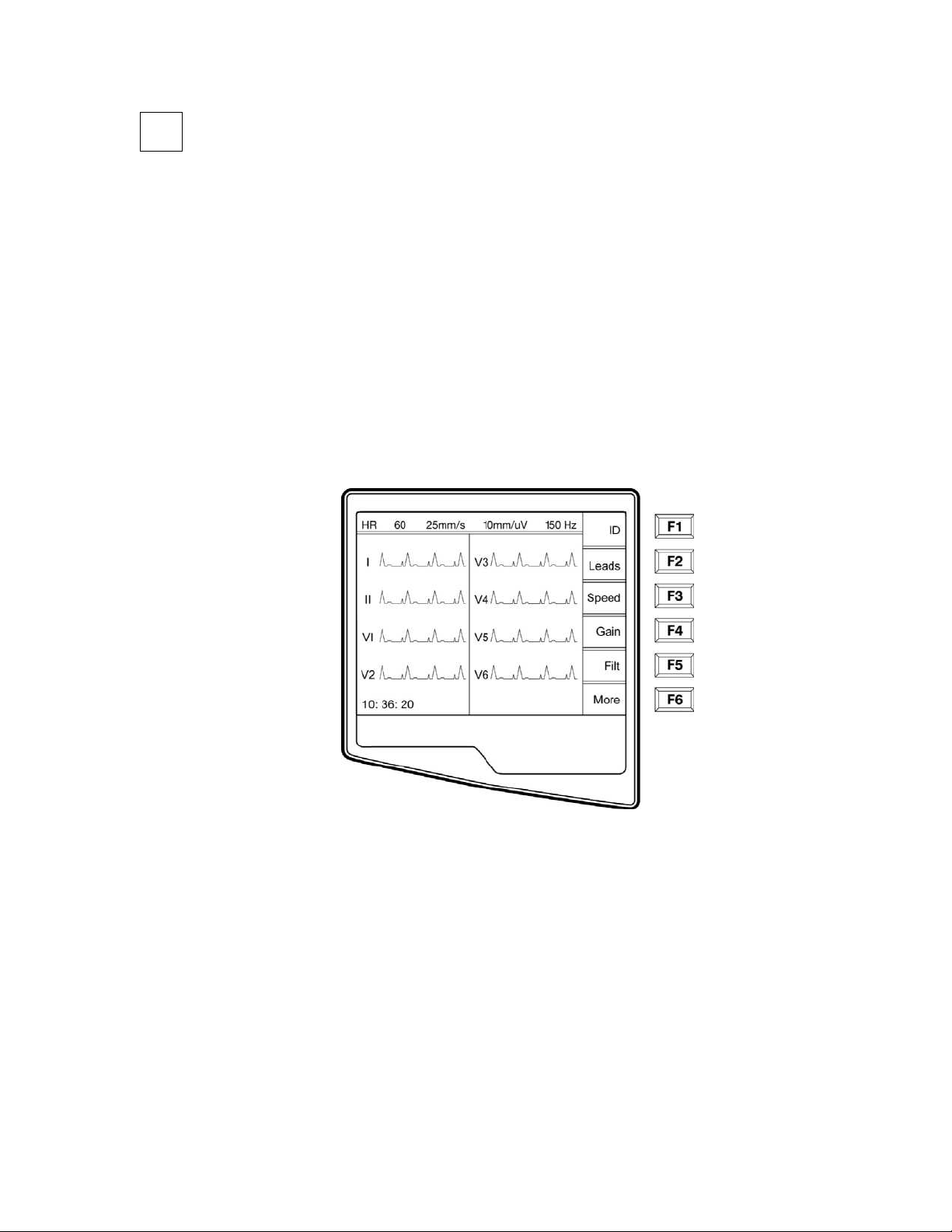
Access Configuration Menus
Four configuration pages define all ELI 250 operational conditions that do not change on a daily or patient-to-patient
basis. Once you set these default conditions, you will rarely need to use the configuration screens again. When you
apply power to the ELI 250, it will operate according to the settings you have selected. To access the configuration
menus:
n Select More (F6) from the Real-Time ECG View.
3-1
ELI 250/210__________________________________________________________________________
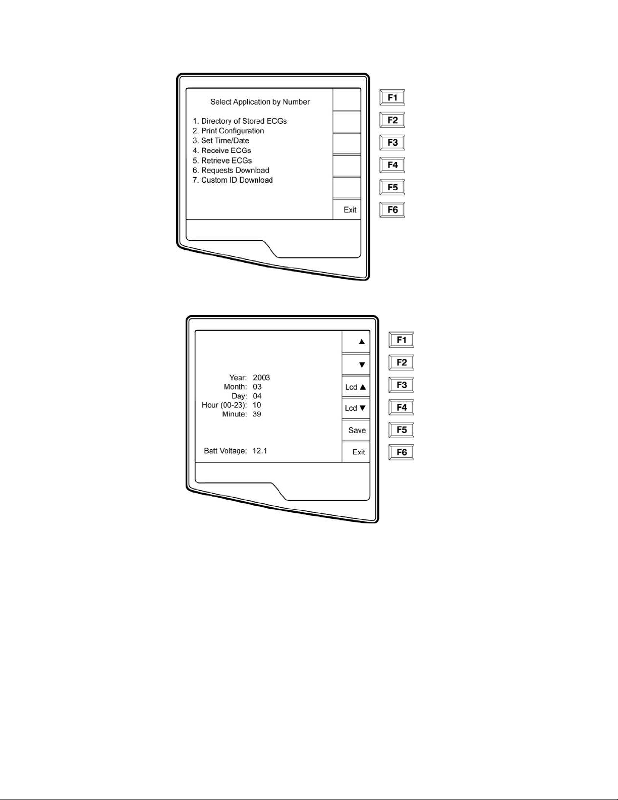
o Select Set Time/Date (number 3) from the application menu
p From the Set Time/Date screen, simultaneously press Ï (SHIFT) + ALT + C. The first
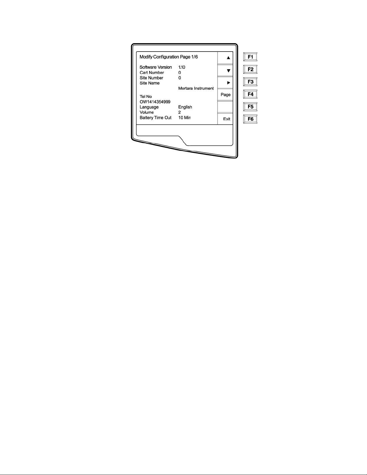
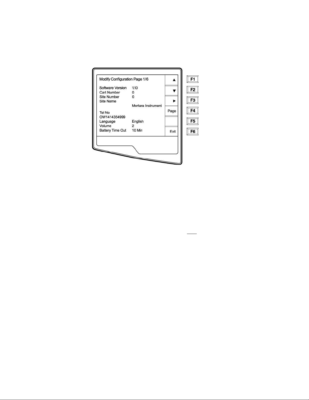
configuration screen will appear. Notice the page indicator in the upper right hand corner on
each screen.
3-2
____________________________________________________________________________Section 3
NOTES: Use Page (F4) to toggle through the configuration pages.
Use ▲ (F1) and ▼ (F2) to move back and forth through each configuration option.
Use ► (F3) to toggle through pre-programmed available settings per configuration field.
Use Exit (F6) to return to the Real-Time ECG View. Any changes you have made will be saved.
Í
Use the BACKSPACE
key to erase entry errors.
The following chart summarizes the configuration screens and the available options for each parameter.
3-3

ELI 250/210__________________________________________________________________________
Summary of Configuration Menus
Configuration
Parameter
Software Version The firmware version of the unit Screen One
Cart Number User-defined (4 digits) Screen One
Site Number User-defined (4 digits) Screen One
Site Name User-defined (up to 30 alphanumeric characters) Screen One
Telephone Number User-defined (up to 30 alphanumeric characters) Screen One
Language Firmware language availability Screen One
Volume Range from 0 – 8 Screen One
Battery Timeout 10min, 30min, 60min Screen One
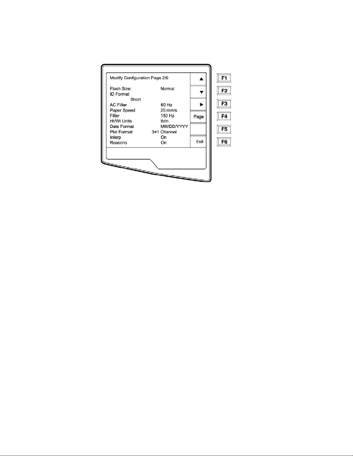
Flash Size Normal memory or Expanded memory (optional) Screen Two
ID Format Short, Long, Standard, Custom (optional) Screen Two
AC Filter None, 60Hz, 50Hz Screen Two
Paper Speed 25mm/sec or 50 mm/sec Screen Two
Filter 40Hz, 150Hz, or 300Hz Screen Two
Height/Weight Units lb/in or kg/cm Screen Two
Date Format US (mm/dd/yyyy) or European (dd.mm.yyyy) Screen Two
Plot Format Channels printed: 3+1, 6, 3+3, 12, 6+6; Cabrera or
Standard
Interpretation Yes or No Screen Two
Reasons Yes or No Screen Two
Definition Configuration Screen
Screen Two
3-4

____________________________________________________________________________Section 3
Append Unconfirmed Report, Reviewed by, Blank Screen Three
#of copies 0 - 9 Screen Three
#ECGs retrieved 0 - 9 Screen Three
3-5

ELI 250/210__________________________________________________________________________
Configuration
Parameter
Delete Rule Post plot, post transmit, post plot/xmt Screen Three
Storage Sensitivity Normal or High Screen Three
Auto-save ECG Yes or No Screen Three
Auto-print ECG Yes or No Screen Three
Baud Rate Serial Baud Rates: 9600, 19200, 38400, 57600, or
115200
Use A4 paper Yes or No Screen Three
Caps Lock Yes or No Screen Three
Rhythm format 3 channel, 6 channel or 12 channel Screen Four
3 Rhythm Lead 1 V1-V6, I, II, III, aVR, aVL, aVF Screen Four
3 Rhythm Lead 2 V1-V6, I, II, III, aVR, aVL, aVF Screen Four
3 Rhythm Lead 3 V1-V6, I, II, III, aVR, aVL, aVF Screen Four
6 Rhythm Lead 1 V1-V6, I, II, III, aVR, aVL, aVF Screen Four
6 Rhythm Lead 2 V1-V6, I, II, III, aVR, aVL, aVF Screen Four
6 Rhythm Lead 3 V1-V6, I, II, III, aVR, aVL, aVF Screen Four
6 Rhythm Lead 4 V1-V6, I, II, III, aVR, aVL, aVF Screen Four
6 Rhythm Lead 5 V1-V6, I, II, III, aVR, aVL, aVF Screen Four
6 Rhythm Lead 6 V1-V6, I, II, III, aVR, aVL, aVF Screen Four
3 + 1 Rhythm Lead V1-V6, I, II, III, aVR, aVL, aVF Screen Five
3 + 3 Rhythm Lead 1 V1-V6, I, II, III, aVR, aVL, aVF Screen Five
Definition Configuration Screen
Screen Three
3-6

____________________________________________________________________________Section 3
3 + 3 Rhythm Lead 2 V1-V6, I, II, III, aVR, aVL, aVF Screen Five
3 + 3 Rhythm Lead 3 V1-V6, I, II, III, aVR, aVL, aVF Screen Five
Default XMT Media RS232, Modem, WLAN, LAN Screen Six
DHCP (LAN only) Yes or No Screen Six
IP Address XXX.XXX.XXX.XXX Screen Six
Def Gateway XXX.XXX.XXX.XXX Screen Six
Sub Net Mask XXX.XXX.XXX.XXX Screen Six
Host IP XXX.XXX.XXX.XXX Screen Six
Port Number XXX.XXX.XXX.XXX Screen Six
SSID Yes or No Screen Six
Channel Number 0, 1, 2, 3..... Screen Six
Security WEP Yes or No Screen Seven
WEP Key 0, 1, 2, 3..... Screen Seven
WEP Key ID 26 digits in 13 sets of two digits Screen Seven
3-7
ELI 250/210__________________________________________________________________________
Configuration Page 1
Software Version
The displayed number identifies the firmware version of your electrocardiograph.
Cart Number
Cart numbers indicate which electrocardiograph transmitted a particular ECG.
Site Number
This option identifies the site of your ELI 250. Site numbers designate the hospital, clinic, or institution for ECG
records stored in a Mortara Instrument, E-Scribe data management system and must
retrieving ECGs from the data management system. You can use up to four digits for the site number, numbers
from 0 –4095 are supported.
Site Name
This option defines your clinic, hospital, or office name. You can enter up to 30 alphanumeric characters. The site
name prints at the bottom, left edge of the ECG printout.
Telephone Number
This option specifies the telephone number for modem transmission (to another unit or to an E-Scribe data
management system). Enter up to 30 alphanumeric characters, and use the BACKSPACE
errors.
To wait for an additional dial tone, use the letter W. For example, you may need to dial a 9 to get an outside line.
EXAMPLE: 9W14145554321
To insert a pause use a comma (,).
To change tone dialing to pulse dialing, use the letter P.
EXAMPLE: P14145554321
be defined for transmitting and
Í
key to erase entry
3-8

____________________________________________________________________________Section 3
(If necessary, you can use both the letter W and the letter P in the same phone number.)
TIP: Instead of entering the configuration menus, use a shortcut to quickly delete or modify a phone number. From
the application screen, simultaneously press Ï (SHIFT) + ALT + P. To edit an existing number, use the
tab key.
Language
There are several languages available on the cardiograph.
CAUTION: upon selecting a new language and exiting the configuration screen, function labels are
immediately translated.
If an unknown language is visible, use the following steps to revert to the language of your country:
1. F6 from Real-Time ECG View
2. Select number 3
3. Simultaneously press Ï (SHIFT) + ALT + C
4. Press F2 (▼) four times
5. Press F3 (►) until the desired language appears
6. F6 to return to Real-Time ECG View
Volume
This option defines the keyboard click loudness. Available settings rage from 0 (off) to 8 (loud).
TIP: Use the BACKSPACE
Battery Timeout
This setting determines when the cardiograph will switch off in order to conserve the battery life of the unit. The
battery timeout will only occur if the keypad has not been depressed for the time specified. The battery timeout
setting is ignored if an active ECG signal is detected, during transmission, or while rhythm printing.
Í
key to erase entry errors
3-9
ELI 250/210__________________________________________________________________________
Configuration Page 2
Flash Size
Flash Size indicates the ECG storage capacity of your electrocardiograph. Normal Flash Size is the standard
memory capacity. If the optional expanded memory has been installed, Expanded will be displayed.
ID Format
This option defines the format for the patient ID information prompts. There are three standard formats: short,
standard, or long. A custom ID format is optional when downloaded from the E-Scribe Data Management System.
The short format includes the patient's last name and first name, patient ID number, date of birth, which will
automatically calculate the age, and gender field.
The standard format includes the patient's last name, patient ID number, age, height, weight, gender, race,
medication 1, medication 2, and a location field.
The long format is identical to the standard format except that it includes the patient's first name, room and comment
fields.
The custom format, which is designed in the Mortara E-Scribe Data Management System, can be downloaded to the
ELI 250. The custom ID format is uniquely designed to meet your facility’s needs. Please see Appendix A to
download a Custom ID.
AC Filter
The ELI 250 removes 60Hz or 50Hz interference. The setting you select depends on the line frequency in your
country. Always use the 60Hz setting in the United States. If the AC interference is present, check to see that the
proper AC filter is selected.
Paper Speed
The writer speed can be configured at 25mm/s or 50mm/s for default ECG printouts. For rhythm printouts and
display, speeds of 5mm/s or 10mm/s are also available. See Section 4 to change speeds for display or rhythm
printing.
3-10
 Loading...