

Mortara ELI-200 User manual
ELI-200
12-Lead
Interpretive
Electrocardiographs
SERVICE
MANUAL
Phone:
414-354-1600
©
Mortara
Milwaukee,
Fax:
Mortara
Mortara
Instrument,
7865
North
Wisconsin
U.S.A
414-354-4760
Instrument,
Part
No.
9507-002B
86th
Inc.,
Inc.
Street
53224
Telex:
Revised
650-277-3627
1991
MORTARA

ELI-200
Service
Manual
Mortara
INSTRUVENT
TABLE
Warrantyinformation.............................
Equipment
1.0
20
Specifications
Performance
1.1
Introduction...................................
1.2
EguipmentReguired......................................
1.3
TestEquipment
1.4
lnitiallSet-Up
1.5
NoiseTest..........................
1.6
ECG,KeyboardandCablelTest.......................
—RhythmTest
1.7
1.8
TeadFaillest...............................
19
Director'Tlest.................................
1.10
Transmit/Receive
1.11
WriterSelfTlest........................................
Testing
Ttoubleshooting.................................
2.1
Equipment
2.2
Introduction...
2.3
FaultisolationTable
2.4
AC On - Blank
2.5 © AC
2.6
On-
Bar
Faint
Illumination
DC
On - “Battery
Appears
2.7 © DC
2.8
On-
DC
On
Keyboard
No
Key
OF
CONTENTS
eee
eee
Set-Up...................
............................................
Geren
.........ooooocccccncncnconcoconocconcnconanonccnos
Tests
......................
Gere
Required
......o.oooccccccnccncnccconcccncnnnosn
......................................
LCD;
No
Pixels
Across
on
Displays
Response
is
Test-Key
Top
of
PixelS...........................
Low”
Message
..….................................
When
Pressed..........................
Press
Illuminated
of
LCD
Response
or
on
DisplaybutNoAudio...................................
2.9
Writer
Test-Printing
Too
Light
or
Too
Dark,orUneven.....................................
2.10
2.11
2.12
Writer
Writer
Modem
Dots,
Test - Gaps
or
No
Printing
Test - No
Motor
Test - No
in
Printing,
at
All
Drive
Dial-Tone
Missing
............................
..........................
or
Touch-ToneAudio..............................
αν
8,
6.00.0000.
certe
6600000000000
eee
.....
5
7
9
9
9
10
10
11
12
13
14
14
15
17
19
19
19
19
21
22
22
23
24
24
25
25
26
Part
No.
9507-002B
3.0
ServiiceandMaintenance....................................
3.1
Overview........................
3.2
ToolsandMaterials........................................
3.3
List
of
Cleaning
3.4
List
of
Repair
3.5
Cleaning
3.6
Preventative
3.7
Cover
3.8
WriterRemoval/installation...........................
3.9
Printhead
3.10
Paper
and
Assembly
Drive
Materials
Materials
Inspecting
Maintenance
Removal
Removal/Installation
Motor
Removal/Installation
eee
...............................
................................,.
Techniques
Schedule
/Installation
..............
................
.............
......................
27
27
27
27
27
28
31
32
32
32
.........
33
1
ELI-200
Service
Manual
Mortara
INSTRUMENT
Addendum:
Септапу
France
Foreign
..........
иена
Illustrations
ани
ан
они н оное
and
Tables
ион
....................
ново
вн
овизинаненнон
оно
нови
06060
85
85
88
Рай
№.
9507-0028
3
Mortara
INSTRUMENT
ELI-200
Service
Manual
4
Part
No.
9507-0028
ELI-200
Service
Manual
Mortara
INSTRUMENT
MORTARA
“Mortara”)
referred
and
a
period
Mortara
Normal
to
as
workmanship
of
one
or
use,
maintenance
information
the
Products
or
conditions:
(a)
(b)
(c)
(d)
(e)
(f)
YOUR
MORTARA
INSTRUMENT,
hereby
an
guides.
Freight
Parts
from
Misapplication,
Product
Accident, a disaster
Alterations
rized
Other
or
warrants
the
“Products”)
under
(1)
year
of
authorized
service
in
accordance
and
This
caused
not
by
damage;
and/or
or
approved
instruction
by
Mortara;
events outside
arising
that
shall
normal
the
date
distributor
maintenance
with
Warranty
any
or
accessories
by
misuse,
or
modifications
under
LIMITED
INC.
Mortara
be
free
use,
service
of
purchase
or
representative
appropriate
does
all
of
the
of
Mortara;
abuse
sheets
and/or
affecting
of
Mortara’s
normal
WARRANTY
(hereinafter
products
from
defects
and
maintenance
of
such
means
operation
instructions
not
apply
following
the
Products
and
the
to
the
operating
circumstances
failure
information
Products;
Products
reasonable
conditions.
referred
(hereinafter
Product
in
material
of
Mortara.
to
from
and/or
to
damage
not
obtained
to
follow
guides;
not
autho-
control
as
for
and
to
the
THE
REMEDY
THE
REPAIR
BOROR
NATION
shall
be
alleged
ranty
period.
will
further
of
the
Products
returned
specifically
OR
MATERIALS,
BY
MORTARA
conditioned
defects
Mortara's
be
to
Mortara's
designated
representative
expressly
Mortara
by
its
that
indirectly
the
Products.
any
loss,
the
purchase
agreed
does
acceptance
Mortara
to
theory
harm
lesser
(except
or
of
price
not
is
an
the
EXCLUDED
ABOVE
IES,
MAGNETIC
ARE
CONSUMABLE
ELECTRODES,
STORAGE
UNDER
REPLACEMENT
OF
TO
upon
promptly
obligations
conditioned
of
all
carrier
principal
by
of
Mortara
that
the
function
and
purchase
not
liable
occurrence
If
Mortara
the
expressed
damage,
the
actual
of
the
Product
FROM
PATIENT CABLES,
MEDIUMS.
THIS
WARRANTY
WITHOUT
ANY
PRODUCTS
HAVE BEEN
receipt
after
discovery
under
upon
the
assumption
charges
place
Mortara
and
liability
as
or
all
risk
of
aninsurer. A purchaser
thereof,
for
loss,
harm
or
consequence
should
be
found
FOUND
DEFECTIVE.
of
notice
thereof
the
with
respect
or
an
authorized
of
loss
Mortara
acknowledges
or
damage
liable
warranty
liability
loss,
THE
harm
when
LIMITED
ITEMS
of
Mortara
or
sold.
SUCH
damage,
WARRANTY
AS
IS
LIMITED
CHARGE
UPON
This
by
Mortara
within
foregoing
by
the
to
any
any
other
distributor
in
transit.
is
limited
ofa
due
therefrom
to
anyone
set
forth
shall
be
or
PAPER,
LEAD
WIRES
FOR
EXAMI-
remedy
of
the
war-
warranty
purchaser
Products
place
and
Product,
and
agrees
directly
relating
under
herein)
limited
the
original
SET
FORTH
BATTER-
AND
TO
LA-
any
as
or
It
is
that
or
to
for
to
Part
No.
9507-002B
EXCEPT
REIMBURSEMENT
AS
OF
SET
LABOR
FORTH
HEREIN
CHARGES,
WITH
A
PURCHASER'S
RESPECT
TO
SOLE
5
Mortara
INSTRUVENT
ELI-200
Service
Manual
EXCLUSIVE
ING
TO
THE
DAMAGES
REPAIR
EXTENT
NOTIFIED
OR
REPLACEMENT
THAT
WITHIN
INCLUDING
BE
LIABLE
DAMAGES,
OF
ANY
KIND,
DER
TORT,
LAW,
OROTHERWISE.
OF
ANY
OTHER
ING,
BUT
NOT
CHANTABILITY
TICULAR
PURPOSE.
REMEDY
PRODUCTS
RESULTING
THE
THE
AGAINST
DEFECT
THE
CLAIM
FOR
FROM
WARRANTY
FOR
FOR INCIDENTAL,
OR
FOR
ANY
OTHER
INCLUDING
NEGLIGENCE
OR
THIS
WARRANTIES,
LIMITED
AND
THE
TO
THE
WARRANTY
MORTARA
ANY
ANY
OF
DEFECTIVE
IS
NOTICED
NEGLIGENCE,
SPECIAL
LOSS,
LOSS
OF
STRICT
WARRANTY
EXPRESS
IMPLIED
FOR
AND
ALL
CAUSE
PRODUCTS
AND
PERIOD.
OR
CONSEQUENTIAL
DAMAGE
PROFITS,
LIABILITY
IS
EXPRESSLY
ORIMPLIED,
WARRANTY
OF
FITNESS
CLAIMS
LOSSES
SHALL
IN
SHALL
OR
WHETHER
THEORIES
RELAT-
AND
BE
TO
MORTARA
NO
EVENT,
MORTARA
EXPENSE
IN
LIEU
INCLUD-
OF
MER-
FOR A PAR-
THE
THE
IS
UN-
OF
6
Part
No.
9507-002B
ELI-200
Service
Manual
Mortara
INSTRUMENT
Instrument
Paper
Type:
Recording
Writer
Recorder
Sensitivity:
Multiple
Speeds:
Time
Output
Standard
Input
Input
Input
Channels:
Impedance:
Dynamic
Electrode
Common
Mode
ELI-200
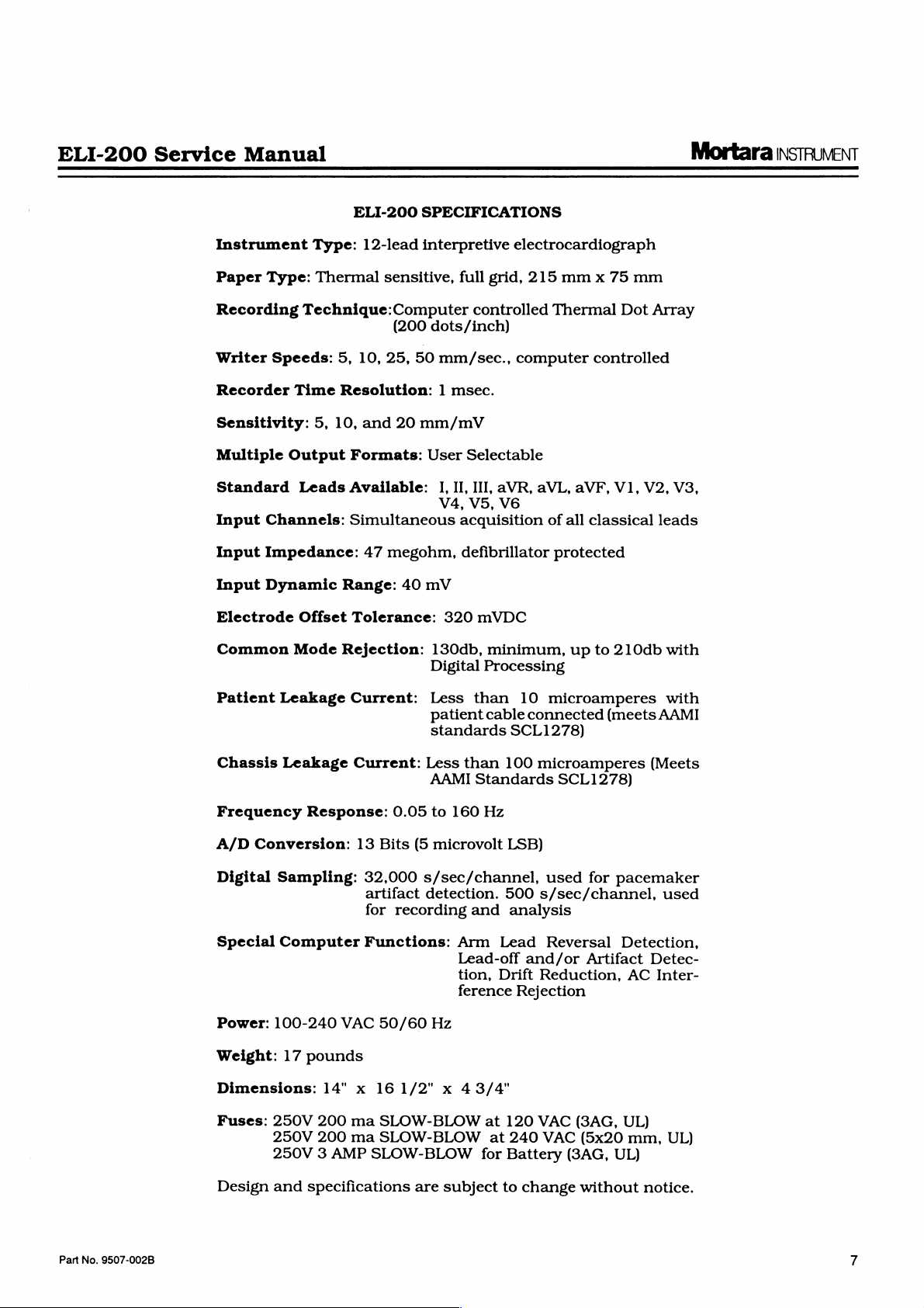
Type:
Thermal
12-lead
SPECIFICATIONS
interpretive
sensitive,
Technique:Computer
(200
5,
10,
25,
50
Resolution: 1 msec.
5,
10,
and
20
mm/mV
Leads
Formats:
Available:
User
Simultaneous
47
megohm,
Offset
Range:
Tolerance:
40
mV
Rejection:
full
grid,
controlled
dots/inch)
mm/sec.,
Selectable
1,
II,
III,
V4,
V5,
acquisition
defibrillator
320
mVDC
130db,
Digital
minimum,
Processing
electrocardiograph
215
mm x 75
Thermal
computer
aVR,
aVL,
controlled
aVF,
V1,
V6
of
all
classical
protected
up
to
210db
mm
Dot
Array
V2,
leads
with
V3,
Patient
Chassis
Frequency
A/D
Digital
Special
Power:
Weight:
Dimensions:
Fuses:
Leakage
Leakage
Conversion:
Sampling:
Computer
100-240
17
250V
250V
250V 3 AMP
Current:
Current:
Response:
13
VAC
pounds
14" x 16
200
ma
200
ma
Less
AAMI
0.05
Bits
(5
32,000
artifact
for
Functions:
s/sec/channel,
detection.
recording
50/60
1/2" x 43/4"
SLOW-BLOW
SLOW-BLOW
SLOW-BLOW
Less
than
patient
standards
cable
than
Standards
to
160
Hz
microvolt
and
Arm
Lead-off
tion,
ference
Hz
at
for
10
connected
SCL1278)
100
LSB)
500
analysis
Lead
and/or
Drift
Rejection
120
at
240
Battery
microamperes
(meets
microamperes
SCL1278)
used
for
pacemaker
s/sec/channel,
Reversal
Reduction,
VAC
VAC
(3AG,
Artifact
(3AG,
(5x20
UL)
Detection,
AC
UL)
mm,
with
AAMI
(Meets
used
Detec-
Inter-
UL)
Part
No.
9507-002B
Design
and
specifications
are
subject
to
change
without
notice.
Mortara
INSTRUMENT
ELI-200
Service
Manual
8
Part
No.
9507-002B
ELI-200
Service
Manual
1.0
PERFORMANCE
TESTING
Mortara
INSTRUMENT
1.1
Introduction:
This
test
procedure
ance
Final
Test
not
necessarily
the
tests
are
section
tests
as
2.0
far
as
encountered.
Sample
provided
lems.
Bio-Tek
is
familiar
If
then
For
available
interconnect
tests,
remote
traces
in
Some
Model
used
for
with
it
is
necessary
another
the
direct
however,
installation.
at
is
based
Procedure,
be
performed
listed.
corresponds
section
of
the
type
of
tests
these
ECG-1
However,
of
which
10.0
traces
Simulator.
performance
the
correct
to
perform
ELI-200
transmit/receive
the
cable.
which
servicing
the
unit
For
on
the
but
it
is
in
the
the
troubleshooting
sequentially
trouble
symptoms
include a writer
as
an
aid
were
derived
testing
waveform
the
used
output
the
transmit/receive
is
fully
tests,
site,
along
modem
for
test
factory
not
Quality
identical,
exact
order
to
the
performance
which
print-out
for
diagnosis
using
the
If a different
the
operator
of
the
type
functional
this
may
is
unit
with
the
transmit/receive
be
located
Assur-
and
need
in
which
guide
in
may
be
are
of
prob-
10-Lead
simulator
must
be
used.
tests,
required.
must
be
proper
at
a
1.2
Leakage
gory
CF
These
circuit
tests
board
assembly
IEC
approved
Equipment
1.2.1
1.2.2
1.2.3
10-Lead
Patient
Resting
N
1.2.4
1.2.5
1.2.6
Roll
Fully
9600
Test
shooting
1.2.7
1.2.8
Test
Digital
shooting
1.2.9
Oscilloscope
printhead
tests
description
medical
should
assembly,
are
removed
Leakage
Required:
Data
Patient
9293-010)
of
thermal
Functional
or
38400
LCD
Keyboard,
Multimeter
equipment
be
performed
the
and
tester
Bio-Tek
ECG-1
input
Cable
8"
ELI-200
for
Assembly
for
and
control
and
diagrams
are
provided
any
time
AC
connector
replaced.
may
be
Any
used.
Simulator
shorting
with
ECG
American
Paper
plug
(P/N
with
Direct
(P/N
14000-004),
Transmit
troubleshooting
and
test
leads,
Probes,
for
circuits.
for
class 1 cate-
in
the
or
the
AAMI
or
9100-006)
Baud
/Receive
section
Marking
Rate
for
for
11.0.
writer,
AC
switch
and/or
Equivalent
set
trouble-
trouble-
troubleshooting
the
(P/
at
Part
No.
9507-002B
9
Mortara
INSTRUMENT
ELI-200
Service
Manual
1.3
1.4
FILTER:
Test
1.3.1
1.3.2
1.3.3
1.3.4
Initial
Note:
1.4.1
AC
Equipment
Connect
(120V
or
240V),
located
Connect
Connect
Install
Set-Up:
Insure a beep
during
Turn
the
on
The
tarily
configuration
on
the
the
on
rear.
the
LCD.
message
on
60Hz
Set-Up:
the
ELI-200
making
the
rear
the
patient
the
shorting
roll
of
is
heard
Performance
the
unit’s
The
message
Press
‘SELF
the
LCD,
parameters,
STORAGE
FORMAT:
to a mains
sure
of
the
cable
plug
ECG
paper.
every
test.
main
‘CHARGING’
the
DC
TEST
followed
the
120V/240V
unit,
is
to
the
simulator.
to
the
patient
time a Key
power
switch,
On
key
on
should
by
the
first
indicating
2.5s
power
set
for
input
should
the
appear
screen
the
source
switch,
120V.
port.
is
pressed
located
keyboard.
momen-
following:
at
appear
of
the
EX
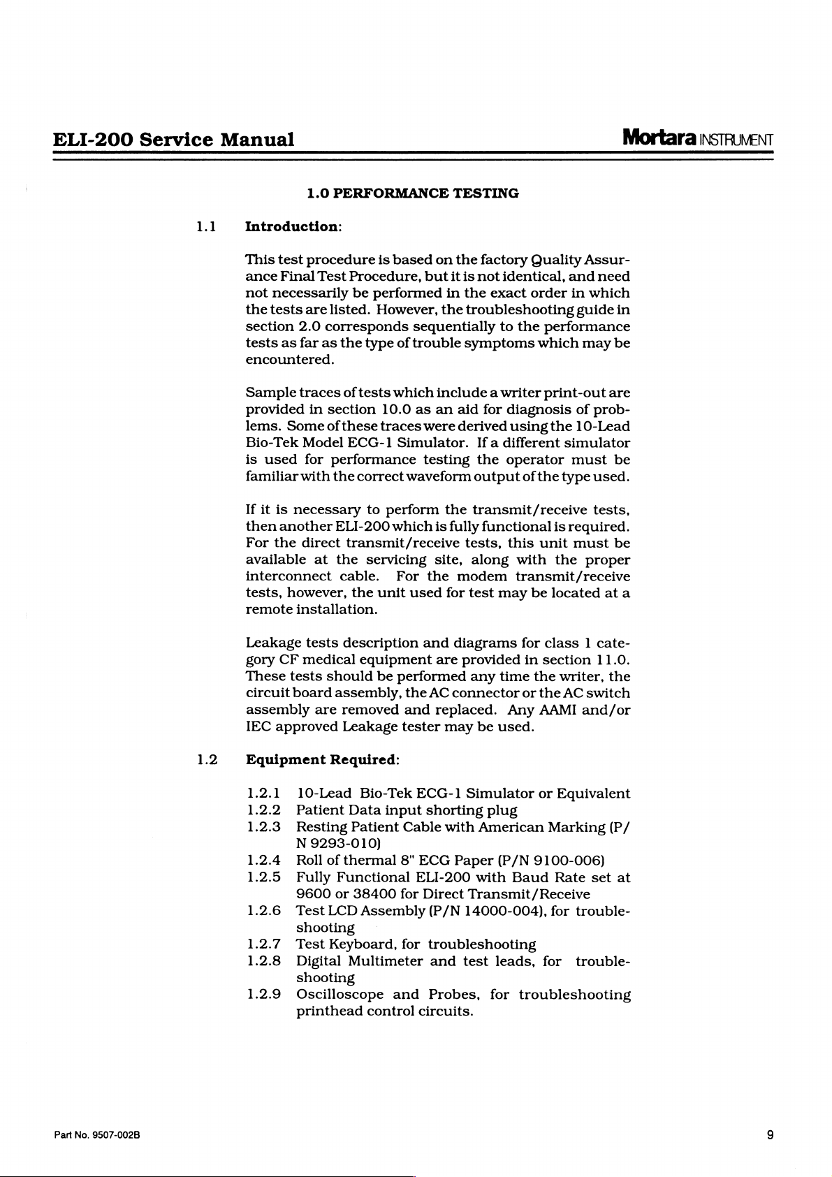
1.4.2
AC
Filter:
Plot
Format:
Plot
Freg:
Units:
Baud
Auto
Site
Cart
ID
Rhythm
Site
LB/IN
Rate:
Save:
#:
Copies
#:
Format:
CH1/II,
Name:
1.4.3
60Hz
INT
100Hz
38400
ON
0
Retrieve
LONG
Lead
Selection
CH2/V1,
Toggle
default
Serials:
CH3/V5
After
the
advances
Illustration
through
parameters
each
Storage
Interp
Plot
Date
Auto
Oueueing:
0
Table
sitename
to
the
following
of
the
as
follows:
Format:
Format:
Channels:
Format:
Delete:
has
OFF
Off
1
been
menu:
1]
options
2.5s | press
REA
3
US
entered,
and
set
ENTER
press
ENTER
press
ENTER
press
ENTER
press
ENTER
press
ENTER
press
ENTER
four
times
press
ENTER
press
ENTER
press
the
ENTER
LCD
the
10
Part
No.
9507-002B
ELI-200
Service
Manual
CURRENT
NEW
DATE
DATE
AND
AND
TIME:
TIME:
Illustration
00/00/00
00/00/00
2
00:00
00:00
Mortara
|\STRUMENT
1.5
NEW
eli
SPF
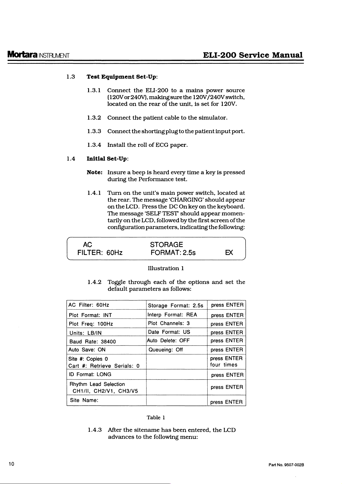
1.4.4
DATE
1.4.5
200
Noise
1.5.1
Setthecurrent
mm/dd/yy
a
24
hour
display
Check
and
returns
AND
press
the
TIME:
the
ENTER
to
25mm/s
Test:
Press
the
'mm/mV'
mm/mV,
tient
and
input
date
by
entering
format.
clock
following
Time
value.
screen:
12/31/88
Illustration
date
and
the
main
10mm/mV
Illustration
connect a shorting
connector.
time
again
menu
key
3
to
4
to
should
Then
17:55
for
the
start
as
shown
100Hz
change
the
numbers
be
press
correct
the
clock.
the
plug
entered
ENTER
reading,
The
here:
Rate:
Gain
at
in
using
???
ID
to
the
the
to
LCD
20
pa-
Part
No.
9507-002B
New
Last
1.5.2
Press
Patient?
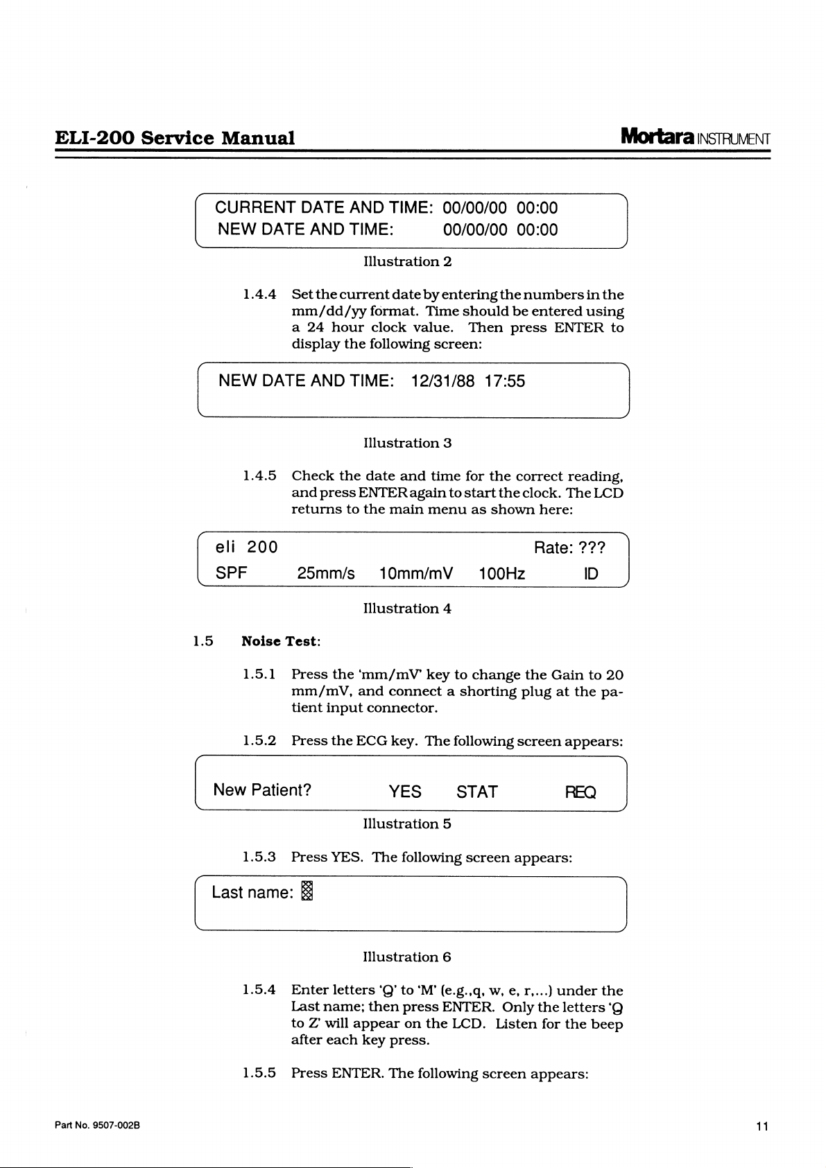
1.5.3
name:
1.5.4
1.5.5
Press
Enter
Last
to Z will
after
Press
ES
the
ECG
Illustration
YES.
Illustration
letters
name;
appear
each
key
ENTER.
key.
YES
The
‘Q’ to
then
press.
The
The
following
STAT
5
following
6
‘M’
(e.g.,q,
press
ENTER.
on
the
LCD.
following
screen
w,
Only
Listen
screen
screen
appears:
e,
r,...)
the
for
appears:
appears:
REQ
under
letters
the
beep
the
‘Q
11
Mortara
INSTRUMENT
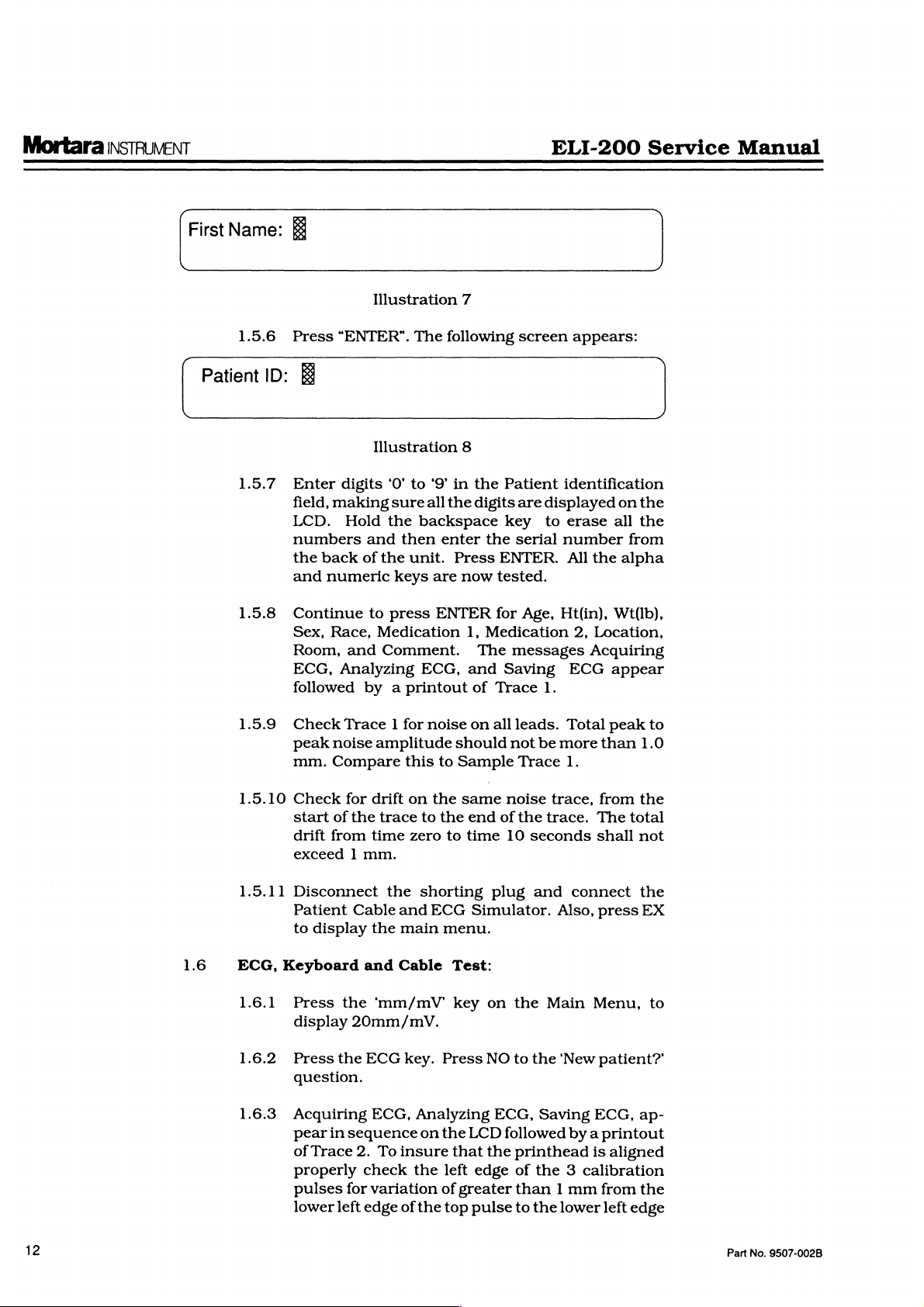
First
Name:
图
ELI-200
Service
Manual
Patient
1.5.6
ID:
1.5.7
1.5.8
1.5.9
Press
“ENTER”.
ES
Enter
field,
LCD.
numbers
the
and
Continue
Sex,
Room,
ECG,
followed
Check
peak
mm.
digits
making
Hold
back
numeric
Race,
and
Analyzing
Trace 1 for
noise
Compare
Illustration
The
Illustration
‘0’
to
sure
the
and
then
of
the
unit.
keys
to
press
7
following
8
‘9’
in
all
the
backspace
enter
Press
are
now
ENTER
Medication
Comment.
ECG,
by a printout
noise
amplitude
this
should
to
Sample
screen
the
Patient
digits
are
key
the
serial
ENTER.
tested.
for
Age,
1,
Medication
The
messages
and
Saving
of
Trace
on
all
leads.
not
Trace
appears:
identification
displayed
to
erase
all
number
All
the
Ht(in),
2,
Location,
Acquiring
ECG
Wt(1b),
appear
1.
Total
peak
be
more
than
1.
on
the
the
from
alpha
to
1.0
1.6
1.5.10
1.5.11
ECG,
1.6.1
1.6.2
1.6.3
Check
start
drift
exceed 1 mm.
for
of
the
from
Disconnect
Patient
to
Cable
display
Keyboard
Press
display
Press
question.
the
20mm/mV.
the
Acquiring
pear
in
sequence
of
Trace
2.
properly
pulses
lower
for
left
drift
on
trace
to
time
zero
the
shorting
and
the
main
and
Cable
'mm/mV
ECG
key.
ECG,
Analyzing
on
To
insure
check
the
variation
edge
of
the
the
the
to
ECG
menu.
Test:
key
Press
the
that
left
of
top
same
greater
noise
end
of
the
time
10
seconds
plug
Simulator.
on
the
NO
to
the
ECG,
LCD
followed
the
printhead
edge
of
than 1 mm
pulse
to
the
trace,
trace.
and
Main
Saving
connect
Also,
‘New
from
the
The
total
shall
not
the
press
EX
Menu,
to
patient?’
ECG,
ap-
by a printout
is
aligned
the 3 calibration
from
the
lower
left
edge
12
Part
No.
9507-002B
ELI-200
Service
Manual
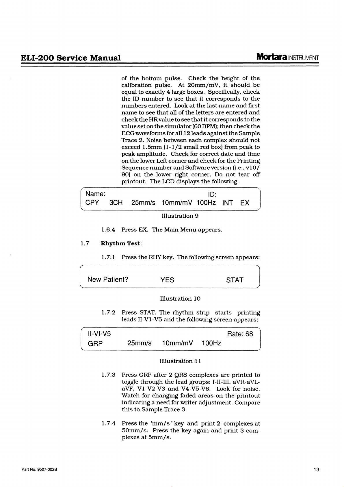
Name:
CPY
of
calibration
equal
the
numbers
name
check
value
ECG
Trace
exceed
peak
on
Sequence
90)
printout.
3CH
the
bottom
to
exactly 4 large
ID
number
entered.
to
see
the
HR
set
on
waveforms
2.
Noise
1.5mm
amplitude.
the
lower
number
on
the
The
25mm/s
pulse.
pulse.
to
At
see
Look
that
all
of
value
to
the
simulator
for
all
between
(1-1/2
Check
Left
corner
and
lower
LCD
right
displays
10mm/mV
Illustration
Check
20mm/mV,
boxes.
that
at
the
letters
see
that
(60
12
leads
each
small
for
and
Software
corner.
9
the
Specifically,
it
corresponds
the
last
name
are
it
corresponds
BPM);
then
against
complex
red
box)
correct
check
for
version
Do
the
following:
ID:
100Hz
height
it
should
entered
check
the
should
from
date
and
the
(i.e.,
not
INT
of
the
be
check
to
the
and
first
and
to
the
the
Sample
not
peak
to
time
Printing
v10/
tear
off
EX
Mortara
INSTRUMENT
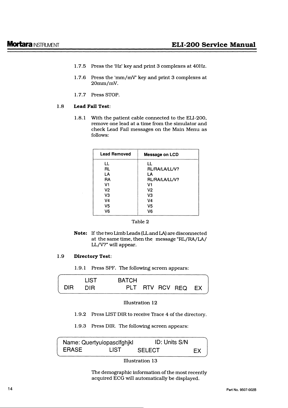
1.7
New
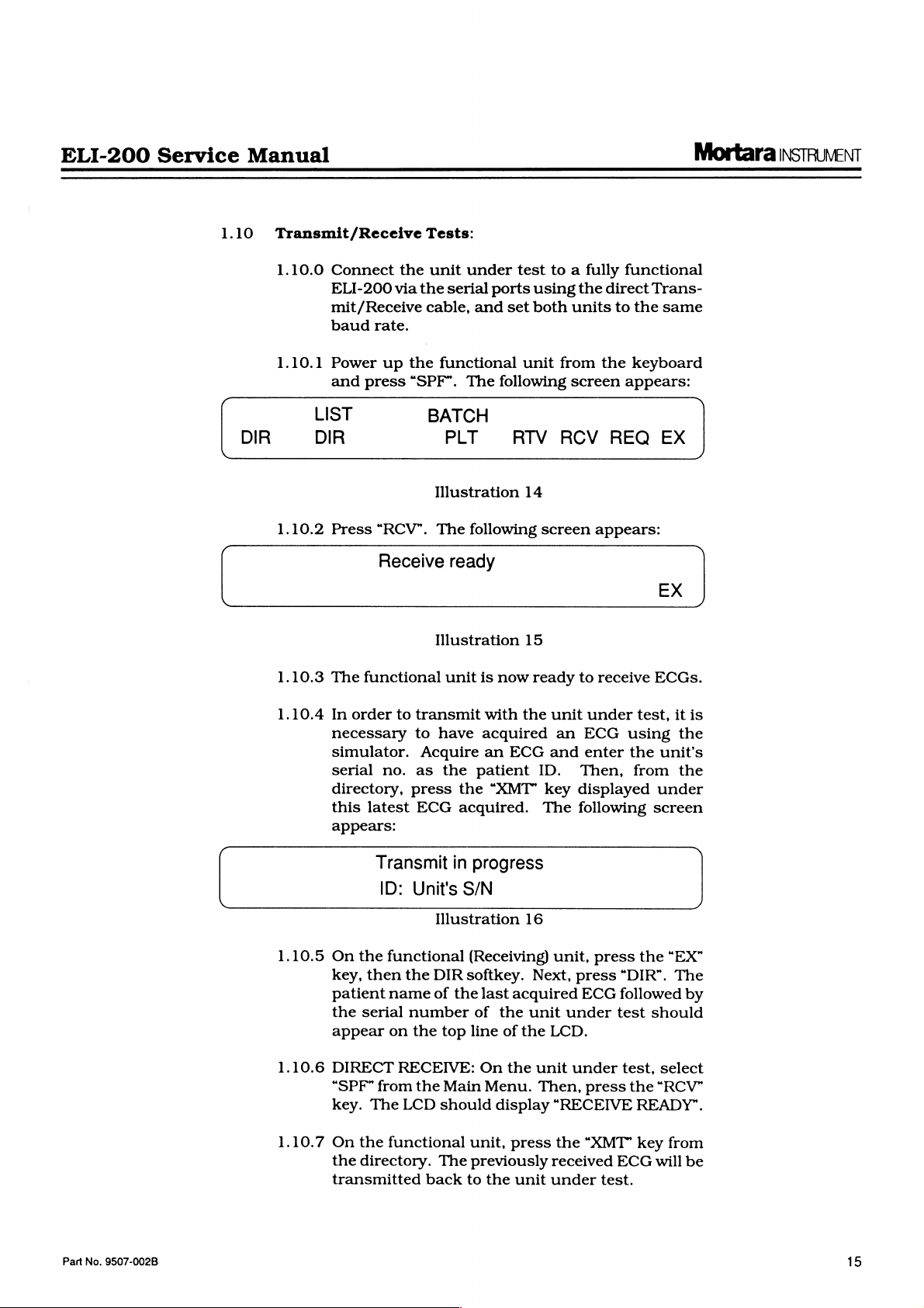
||-М-\У5
GRP
1.6.4
Press
Rhythm
1.7.1
Press
Patient?
1.7.2
1.7.3
Press
leads
Press
toggle
aVF,
Watch
indicating a need
this
EX.
Test:
the
STAT.
II-V1-V5
25mm/s
GRP
through
V1-V2-V3
to
Sample
The
RHY
after 2 QRS
for
changing
Main
Menu
key.
The
YES
Illustration
The
rhythm
and
the
following
10mm/mV
Illustration
the
lead
and
V4-V5-V6.
faded
for
writer
Trace
3.
appears.
following
10
strip
screen
100Hz
11
complexes
groups:
I-II-III,
areas
adjustment.
screen
STAT
starts
Rate:
are
Look
on
the
appears:
printing
appears:
68
printed
aVR-aVL-
for
noise.
printout
Compare
to
Part
No.
9507-002B
1.7.4
Press
the
50mm/s.
plexes
at
5mm/s.
‘mm/s’
Press
key
the
and
key
print 2 complexes
again
and
print 3 com-
at
13
Mortara
INSTRUMENT
ELI-200
Service
Manual
1.8
1.7.5
1.7.6
1.7.7
Lead
1.8.1
Press
Press
20mm/mV.
Press
Fail
Test:
With
remove
check
follows:
the
the
STOP.
the
Lead
Lead
LL
RL
LA
RA
VI
V2
V3
V4
V5
V6
‘Hz’
'mm/mV”
patient
one
lead
Fail
Removed
key
and
cable
at a time
messages
Table
print 3 complexes
key
and
print 3 complexes
connected
from
the
on
the
Message
LL
RL/RA/LA/LL/V?
LA
RL/RA/LA/LL/V?
VI
V2
V3
V4
V5
V6
2
on
to
the
simulator
Main
LCD
at
40Hz.
at
ELI-200,
and
Menu
as
1.9
DIR
Name:
ERASE
Note:
Directory
1.9.1
If
at
LL/V?”
Press
LIST
the
the
Test:
two
same
will
SPF.
Limb
time,
appear.
The
BATCH
DIR
1.9.2
1.9.3
Press
Press
LIST
DIR.
DIR
The
Quertyuiopasclfghjkl
LIST
The
demographic
acquired
ECG
Leads
PLT
Illustration
(LLand
then
the
following
RIV
to
receive
following
Trace 4 of
SELECT
Illustration
information
will
automatically
LA)
message
screen
RCV
12
screen
ID:
Units
13
of
are
disconnected
“RL/RA/LA/
appears:
REQ
the
appears:
S/N
the
most
be
displayed.
EX
directory.
EX
recently
14
Part
No.
9507-002B
ELI-200
Service
Manual
Mortara
INSTRUVENT
1.10
DIR
Transmit/Receive
1.10.0
Connect
ELI-200
mit
/Receive
baud
rate.
1.10.1
Power
and
press
LIST
DIR
1.10.2
1.10.3
Press
The
functional
"RCV”.
Receive
via
up
Tests:
the
unit
the
serial
cable,
the
functional
“SPF”.
BATCH
PLT
Illustration
The
ready
Illustration
unit
under
test
ports
and
set
unit
The
following
RIV
14
following
15
is
now
to a fully
using
the
both
units
from
screen
RCV
screen
ready
to
functional
direct
Trans-
to
the
the
keyboard
appears:
REQ
appears:
receive
same
EX
EX
ECGs.
1.10.4
In
order
to
necessary
simulator.
serial
no.
directory,
this
latest
transmit
to
have
Acquire
as
the
press
ECG
the
acguired.
with
the
acquired
an
ECG
patient
“XMT"
unit
an
and
ID.
key
The
under
ECG
enter
Then,
test,
using
the
from
displayed
following
it
is
the
unit's
the
under
screen
appears:
Transmit
ID:
1.10.5
1.10.6
1.10.7
On
the
functional
key,
then
patient
the
appear
DIRECT
“SPF”
key.
On
the
transmitted
name
serial
on
RECEIVE:
from
The
the
functional
directory.
the
LCD
in
Unit's
Illustration
DIR
of
the
number
the
top
the
Main
should
The
back
progress
S/N
16
(Receiving)
softkey.
last
acquired
of
the
unit
line
of
the
On
the
Menu.
display
unit,
press
previously
to
the
unit
unit,
Next,
under
LCD.
unit
Then,
“RECEIVE
the
received
under
press
press
ECG
under
press
“KMT”
test.
the
“EX”
“DIR”.
followed
test
should
test,
select
the
“RCV”
READY”.
key
from
ECG
will
The
by
be
Part
No.
9507-002B
15
Mortara
INSTRUMENT
ELI-200
Service
Manual
1.10.8
1.10.9
1.10.10
1.10.11
On
the
unit
under
Menu.
Then,
select
screen. A printout
originally
with
this
Now
This
then
change
the
process
deleted.
of
the
column
MODEM
must
at
an
unit
Press
CLOCK”
the
“38400”
“1200”.
number
the
transmitted
an
“X”
to
Sample
delete
is
done
pressing
to
RCR
arrow
keys,
until
Now
directory.
labeled
TRANSMISSION:
be
available,
outside
under
“ALT”
screen.
BAUD
RATE
and
Press
of
the
numeric
under
Trace
each
by
selecting
the
when
select
all
press
DEL.
location
test
to a phone
and
the
“ENTER”
unit
keys.
record
Press
test,
select
“LIST
of
the
directory
and
the
“XMT”
4.
on
each
DEL
key . (This
it
has
each
records
LIST
DIR
You
will
either
“SPF”
to
at
do
to
“CONF”
selection
baud
rate
twice
being
transmitted
“SPF”
from
DIR"
from
will
then
re-received
column.
the
unit
under
record
individually,
Key
been
pressed.)
record
of
now
A
this
and
the
directory
to
obtain a printout
see
an
fully
functional
the
same
location
test.
Connect
line.
access
field
the
and
“ENTER
appears.
should
and
set
to
the
Main
the
show
ECG
Compare
label
Using
repeat
"X"
in
“CONF/
Press
switch
the
phone
by
using
next
the
test.
will
the
are
the
unit
or
the
till
to
Note:
1.10.12
1.10.13
1.10.14
If a number
an
outside
uppercase
“ENTER”
pears;
Press
From
has
by
display
then,
“SPF”
the
not
been
pressing
to
Connect
line
and
Press
“ALT”
CLOCK”
the
BAUD
“38400”
“1200”.
number
twice
of
to
return
is
necessary
line,
letter
until the
press
from
directory
transmitted
the
access
the
functional
power
up
and
screen.
RATE
and
the
Press
“ENTER”
the
unit
to
to
access a dial
separate
“W”.
“CONF/CLOCK”
the
the
the
(i.e.
“EX”
Main
9W3541600).
key.
printout,
from
appropriate
that
record.
(Receiving)
from
the
“SPF”
Press
selection
baud
to
“CONF”
field
rate
twice
under
the
test.
Main
Menu.
numbers
Menu.
select
the
Press
an
unit
arrow
unit
keyboard.
access
and
the
“ENTER”
appears.
should
and
set
Press
the
tone
by
Press
screen
“DIR”.
ECG
that
under
key
on
to a phone
“CONF/
Press
switch
the
phone
“EX”
for
the
ap-
test
the
till
to
key
16
Part
No.
9507-002B
ELI-200
Service
Manual
Mortara
INSTRUMENT
1.10.15
1.10.16
1.10.17
1.10.18
1.10.19
Press
the
The
LCD
On
the
transmit
tone
and
the
receiving
ECG”
should
After
the
on
the
“STOP”
“SPF”,
receive
then
MODEM
press
the
“DIR.”
“XMT”
test.
key
Listen
number
observe
CEIVING
When
on
the
the
the
unit
functional
“SPF”
should
unit
under
the
the
phone
message:
LCD
key
of
“RCV”
an
ECG.
RECEIVE:
“STOP”
Next,
to
fora
being
the
LCD
ECG”.
message:
under
key,
display
test,
selected
number
unit.
The
appear
on
“RECEIVE
of
the
the
unit
to
allow
On
key,
press
send
dial
SELECT
the
tone,
dialed.
displaying
“RECEIVE
test,
unit
and
then
press
“RECEIVE
press
ECG.
being
message:
the
LCD.
receiving
under
the
the
followed
ECG
followed
On
the
press
turn
it
the
READY”.
the
“XMT”
Listen
for
dialed.
“RECEIVING
READY”
unit,
test,
followed
unit
under
functional
by
“SPF”,
twice.
to
the
unit
by
unit
under
the
message:
READY”
the
“STOP”
off.
“RCV”
the
Observe
appears
press
Press
the
appears
key
key.
key
to
dial
the
by
test
to
unit,
then
the
under
phone
test,
“RE-
on
1.11
1.10.20
1.10.21
Writer
Note:
1.11.0
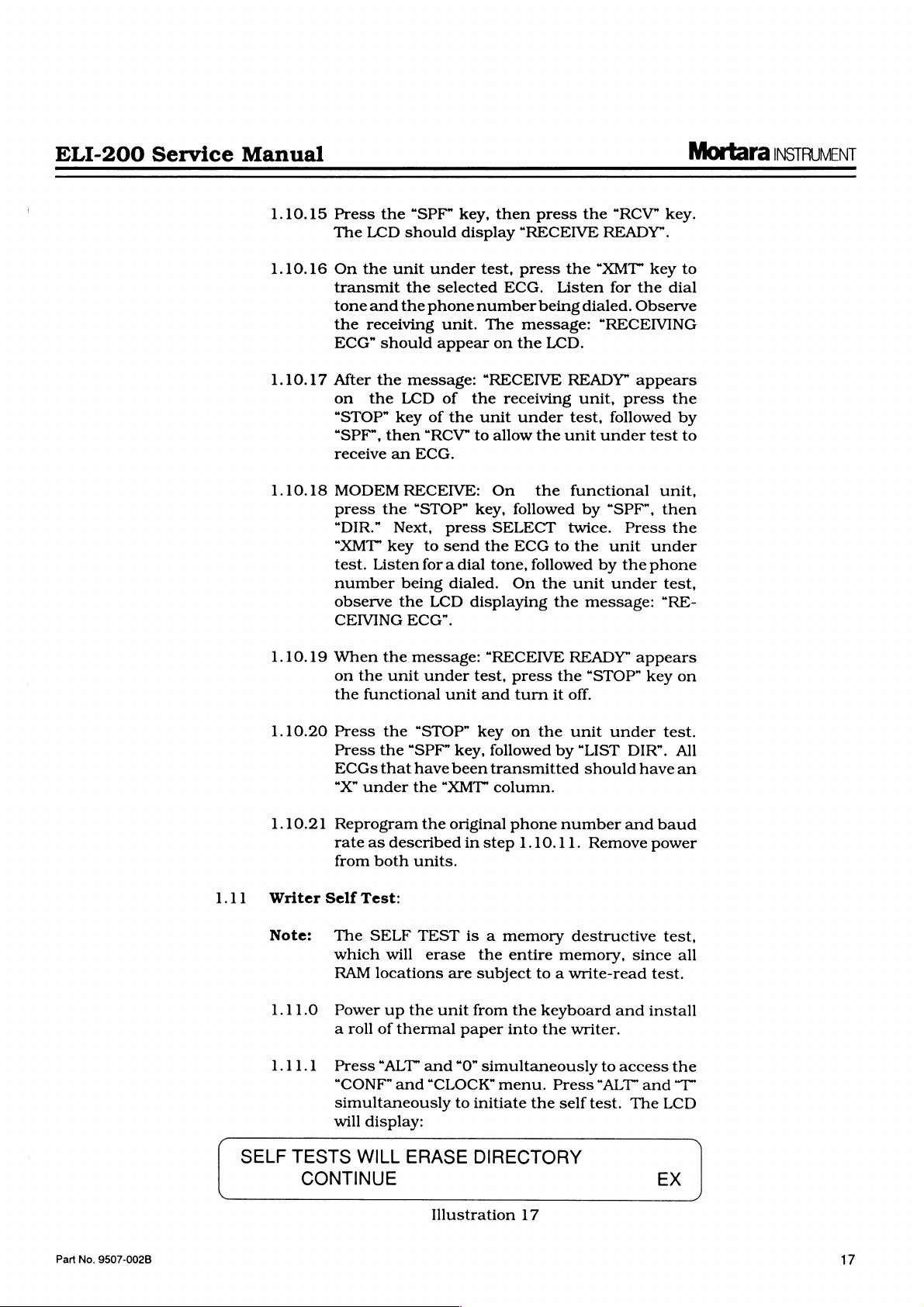
1.11.1
SELF
Press
Press
ECGs
“X”
Reprogram
rate
from
Self
The
which
RAM
Power
a
roll
Press
“CONF”
simultaneously
will
TESTS
CONTINUE
the
the
that
under
as
described
both
Test:
SELF
will
locations
up
of
thermal
“ALT
and
display:
WILL
“STOP”
“SPF”
have
the
“XMT”
the
original
units.
TEST
erase
are
the
unit
and
“CLOCK”
ERASE
Illustration
key
on
key,
followed
been
transmitted
column.
phone
in
step
1.10.11.
is a memory
the
entire
subject
from
the
paper
“0”
to
into
simultaneously
menu.
initiate
DIRECTORY
17
the
unit
under
by
“LIST
number
DIR”.
should
and
Remove
destructive
memory,
to a write-read
keyboard
the
Press
the
self
and
writer.
to
access
“ALT”
test.
havean
baud
power
since
test.
install
and
The
EX
test.
All
test,
all
the
“T”
LCD
Part
No.
9507-002B
17
Mortara
INSTRUMENT
SELF
eli
200
TEST
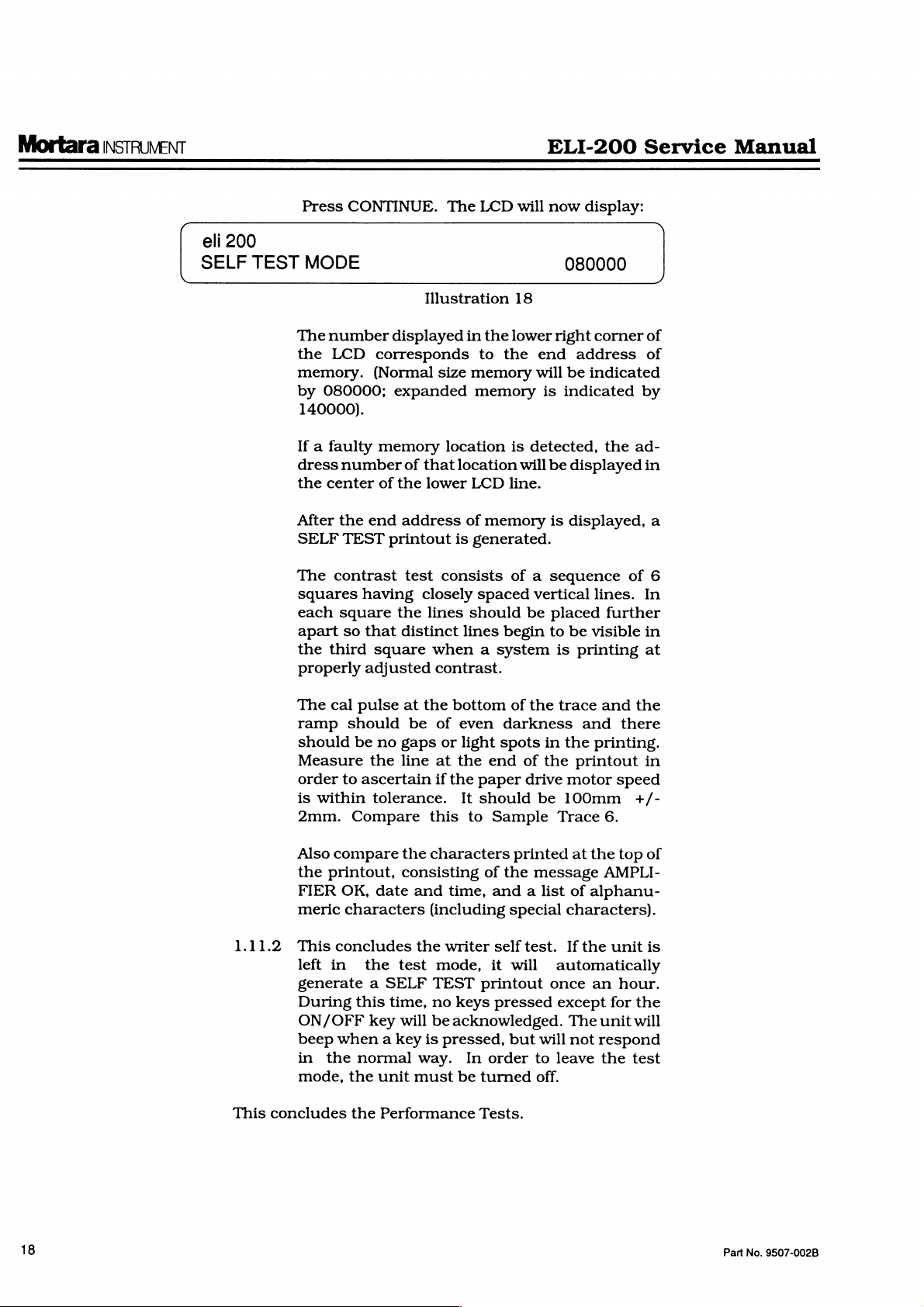
Press
CONTINUE.
MODE
The
number
the
LCD
memory.
by
080000;
140000).
The
Illustration
displayed
corresponds
(Normal
size
expanded
LCD
in
the
to
the
memory
memory
will
18
lower
end
will
is
ELI-200
now
display:
080000
right
corner
address
be
indicated
indicated
Service
of
of
by
Manual
If a faulty
dress
number
the
center
After
the
end
SELF
TEST
The
contrast
squares
each
apart
the
properly
The
ramp
should
having
square
so
third
cal
pulse
should
be
that
adjusted
Measure
order
to
ascertain
is
within
2mm.
Also
the
FIER
meric
Compare
compare
printout,
OK,
characters
memory
of
that
of
the
lower
address
printout
test
closely
the
lines
distinct
square
when a system
at
the
be
no
gaps
the
line
tolerance.
this
the
characters
consisting
date
and
(including
location
location
LCD
of
memory
is
generated.
consists
spaced
should
lines
contrast.
bottom
of
even
or
light
at
the
end
if
the
paper
It
should
to
Sample
of
time,
and a
is
detected,
will
be
displayed
line.
is
displayed,
of a sequence
vertical
be
placed
begin
to
be
is
printing
of
the
trace
darkness
spots
of
drive
in
the
be
and
the
printout
motor
100mm
Trace
printed
the
special
at
message
list
of
characters).
the
ad-
in
a
of
6
lines.
In
further
visible
in
at
and
the
there
printing.
in
speed
+/-
6.
the
top
of
AMPLI-
alphanu-
18
1.11.2
This
This
concludes
left
in
generate a SELF
During
this
ON/OFF
beep
when a key
in
the
normal
mode,
concludes
the
the
the
test
time,
key
will
unit
Performance
the
writer
mode,
TEST
no
keys
be
acknowledged.
is
pressed,
way.
must
In
be
self
test.
it
will
printout
pressed
but
order
turned
Tests.
If
the
unit
automatically
once
an
except
will
to
leave
The
not
for
unitwill
respond
the
off.
is
hour.
the
test
Part
No.
9507-002B
ELI-200
Service
Manual
2.0
TROUBLESHOOTING
Mortara
INSTRUMENT
2.1
2.2
2.3
Equipment
See
“Performance
Note:
Required:
An
Oscilloscope
tween a faulty
Introduction:
Since
repair
of
subassemblies,
troubleshooting
component
matics,
parts
emergency
In
order
display
should
Also,
necessary
Fault
level.
and
an
of
this
manual
repairs.
to
avoid
menus
be
installed
remove
for
Isolation
the
servicing.
Testing,”
Section
may
be
necessary
printhead
the
ELI-200
including
guide
does
is
the
not
limited
entire
extend
However, a hardware
assembly
confusion
or
messages, a current
battery
Table:
in
in
drawing
case
the
fuse
of
on-site
with
circuit
during
1.0
or
the
to
circuit
to
description,
are
regard
board
to
isolate
circuit
board.
replacement
board,
the
circuit
provided
board
in
modifications
to
differences
set
of
software
during
any
testing.
disassembly
be-
of
the
sche-
other
or
in
TROUBLE
2.3.1
2.3.2
2.3.3
2.3.4
2.3.5
2.3.6
2.3.7
SYMPTOMS
AC
On - Blank
no
pixels
AC
or
faint
AC
appears
missing
illuminated.
On - Bar
illumination
On - “Charging”
but
with
between.
AC On - Any
displayed
DC
On - “Battery
appears
DC
On - No
other
on
pressed.
DC
On - Bar
faint
illumination
stays
on).
LCD,
across
top
message
characters
or
without
other
message
than
Low”
display.
response
across
top
of
of
LCD
of
pixels.
are
spaces
is
“charging.”
message
when
key
of
LCD
pixels
(unit
is
or
DIAGNOSIS
See
Par.
See
Par.
See
Par.
See
Par.
See
Par.
See
Par.
See
Par.
2.4
2.5
2.5
2.5
2.6
2.7
2.5
Part
No.
9507-002B
19
Mortara
INSTRUMENT
ELI-200
Service
Manual
2.3
Fault
Isolation
TROUBLE
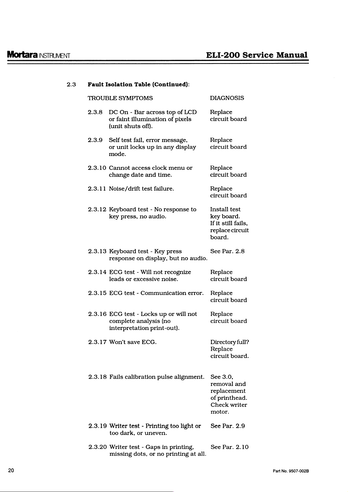
2.3.8
2.3.9
2.3.10
2.3.11
2.3.12
2.3.13
Table
SYMPTOMS
DC
On - Bar
or
faint
illumination
(unit
shuts
Self
test
fail,
or
unit
locks
mode.
Cannot
change
Noise/drift
access
date
Keyboard
key
press,
Keyboard
response
(Continued):
across
off).
error
up
in
clock
and
time.
test
failure.
test - No
no
audio.
test - Key
on
display,
top
of
of
pixels
message,
any
display
menu
response
press
but
no
LCD
or
to
audio.
DIAGNOSIS
Replace
circuit
board
Replace
circuit
board
Replace
circuit
board
Replace
circuit
Install
key
If
replace
board.
it
still
board
test
circuit
board.
See
Par.
fails,
2.8
2.3.14
2.3.15
2.3.16
2.3.17
2.3.18
2.3.19
ECG
test - Will
leads
or
excessive
ECG
test - Communication
ECG
test - Locks
complete
analysis
interpretation
Won't
Writer
Fails
calibration
too
dark,
save
ECG.
test - Printing
or
uneven.
not
recognize
noise.
up
or
will
(no
print-out).
pulse
alignment.
too
error.
not
light
Replace
circuit
Replace
circuit
Replace
circuit
Directory
Replace
circuit
See
removal
replacement
of
motor.
or
See
board
board
board
board.
3.0,
printhead.
Check
writer
Par.
full?
and
2.9
20
2.3.20
Writer
missing
test - Gaps
dots,
or
in
no
printing
printing,
at
all.
See
Par.
2.10
Part
No.
9507-002B
ELI-200
Service
Manual
Mortara
INSTRUMENT
2.3
Fault
TROUBLE
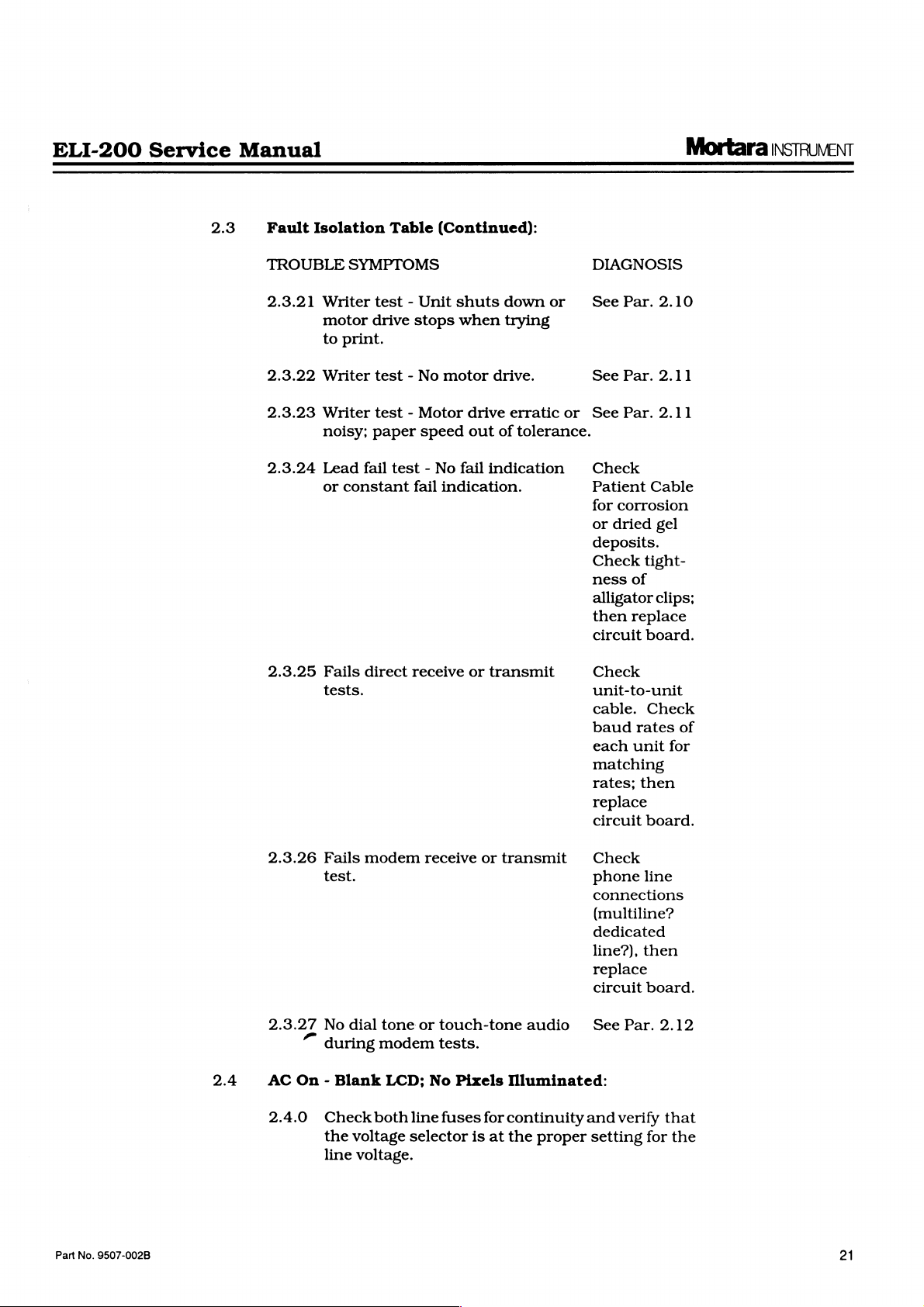
2.3.21
2.3.22
2.3.23
2.3.24
2.3.25
Isolation
SYMPTOMS
Writer
motor
to
print.
Writer
Writer
noisy;
Lead
fail
or
constant
Fails
direct
tests.
Table
test - Unit
drive
test - No
(Continued):
stops
motor
test - Motor
paper
speed
test - No
fail
indication.
receive
shuts
when
drive
out
fail
or
down
or
trying
drive.
erratic
of
tolerance.
indication
transmit
DIAGNOSIS
See
See
or
see
Check
Patient
for
or
deposits.
Check
ness
alligator
then
circuit
Check
unit-to-unit
cable.
baud
each
matching
rates;
replace
circuit
Par.
2.10
Par.
2.11
Par.
2.11
Cable
corrosion
dried
gel
tight-
of
clips;
replace
board.
Check
rates
unit
then
board.
of
for
Part
No.
9507-002B
2.4
2.3.26
2.3.27
AC
On - Blank
2.4.0
Fails
test.
No
dial
during
Check
the
voltage
line
voltage.
modem
tone
modem
LCD;
both
receive
or
touch-tone
tests.
No
Pixels
line
fuses
selector
or
transmit
Illuminated:
for
continuity
is
at
the
audio
proper
Check
phone
connections
(multiline?
dedicated
line?),
line
then
replace
circuit
See
and
setting
board.
Par.
verify
for
2.12
that
the

Mortara
INSTRUVENT
ELI-200
Service
Manual
2.4.1
2.4.2
2.4.3
2.4.4
Disconnect
wire
from
volts
across
switch.
age.
switch
connect
yellow
terminals.
red/yellow
replace
is
present
tinue.
Connect
up
for
the
positive
the
J6.
the 2 wires.
The
multimeter
If
it
does
terminals
to,
then
wires
that
Ifthe
wires,
the
AC
across
the
DC
volts
lead
violet
Connect a multimeter
not,
check
plug
voltage
replace
connector
negative
to
the
first
Approximately + 20
replace
Connect
cathode
present.
Connect
pin
replace
the
the
of
If
the
should
the
circuit
positive
D17.
+ 5
not,
replace
meter
be
less
circuit
wire
from
Turn
should
check
that
the
across
into
is
present
across
blue
the
the
assembly.
the
blue
and
lead
of
negative
to
the
anode
VDC
should
board.
lead
VDC
+/-0.2
the
circuit
to
U29
pin
than + 0.75
board.
Otherwise,
J5
on
read
and
the
black
other
at
switch.
violet
the
multimeter.
end
of
of
be
of
the
VDC
6.
The
VDC.
and
the
set
up
the
AC
the
line
the
AC
violet
and
set
of
the
black
If
not,
If
the
voltage
wires,
C24.
Connect
D13,
then
present.
meter
should
board.
voltage
If
not,
continue.
blue
for
AC
power
volt-
power
wires
red/
switch
and
then
con-
Set
D8.
If
not,
to
the
be
at
that
then
2.5
2.4.5
AC
On - Bar
of
Pixels:
2.5.0
2.5.1
2.5.2
Remove
to
whether
board.
J15.
Across
power
Turn
or
not
Replace
Top
from
on
the
the
With a multimeter
between
cathode
+5.0
the
of
+/-0.2
negative
D17
(pos.
VDC.
board.
Move
the
ground
voltage
+5.0
+/-0.2
meter
(right
at
the
negative
side
positive
VDC.
board.
Remove
to
“charging”
LCD
power
J15,
and
assembly.
from
turn
message
If
the
unit.
the
AC
problem
LCD
of
LCD
set
up
end
lead).
If
not,
of
spark
end
If
not,
the
unit.
on
the
comes
not,
replace
power
is
or
the
or
for
of
C24
The
then
lead
gap
of
then
AC
up,
Connect
again
the
LCD
circuit
Faint
DC
Volts,
(neg.
voltage
replace
to
isolated
RL).
C100.
replace
Connect
power
replace
the
circuit
the
test
LCD
and
verify
or
the
circuit
board.
Illumination
measure
lead)
and
the
should
the
be
circuit
analog
Measure
It
should
the
the
switch.
the
circuit
test
LCD
If
unit’s
the
be
the
board.
22
2.6
DC
On - “Battery
Low”
Message
Appears
on
Display:
Part
No.
9507-002B
ELI-200
Service
Manual
Mortara
INSTRUVENT
2.6.0
2.6.1
Note:
2.6.2
2.6.3
With a multimeter
across
The
between
charge,
This
Connect
negative
ode
minimum.
connect a DC
current
replace
If
in
cluding
Press
up
for
Witha
pin
than
U14
battery
It
VDC
+4
batteries
replace
each
voltage
step
of
D8.
the
batteries
memory
the
in
the
the
“battery
multimeter,
8.
It
the
pin
voltage.
should
(measured
VDC
individual
should
+4.0
and
otherwise
should
the
negative
end
of
C24
The
Disconnect
ammeter
should
the
be
circuit
are
or
any
date
and
keyboard DC
set-up
menu,
low”
should
be
battery
3.
It
should
Measure
be
OV,
across
if
they
are
charged
the
circuit
set
up
for
set
of
be
+6.0
VDC
+6.0
VDC,
replace
be
done
under
lead
from
and
positive
voltage
less
one
in
than
should
of
series.
300
board.
disconnected,
special
time,
set-up
will
On
exit
be
key.
to
message.
measure
the
approximately
voltage.
Measure
be
about
the
if
the
batteries
all
three),
are
below
and
any
board.
DC
Volts,
battery
minimum.
put
the
load.
the
lead
be
the
battery
The
pA.
any
parameters,
lost.
If
the
Main
DC
8.6
0.08
voltage
are
and
+16.0
of
these
measure
terminals.
the
unit
low
battery.
meter
to
the
+18.0
leads
keep-alive
Ifitis
greater,
ECGS
unit
Menu.
voltage
VDC
the
voltage
times
at
U29
above
greater
VDC.
tests
If
it
is
on
to
the
cath-
VDC
and
stored
in-
comes
Check
at
U14
lower
at
the
pin
4.
+16.0
than
If
the
fail,
Part
No.
9507-002B
2.7
DC
On - No
2.7.0
2.7.1
Response
Refer
to
and
keep-alive
teries
check
HA,
check
should
on
+5.0
visible
to
be
Key
on
VDC
on
verify
working.
pressing
the
key
Ifthe
+5V
there
is
at
J12
and
replace
Unit's
Keyboard.
When
steps
7.3.0
current
out
good
the
voltage
approximately
the
keyboard.
+/-0.2
the
VDC.
display,
whether
If
the
some
of
the
click
from
does
not
no
Key
click,
plug
in a test
the
Circuit
DC
and
7.3.1
measurement.
and
at
+4.4
The
If
then
or
not
test
LCD
keyboard
the
speaker.
turn
on,
then
disconnect
Board.
On
Key
for
the
current
the
cathode
VDC.
voltage
it
does,
substitute
the
LCD
remains
keys
the
LCD
keyboard.
Otherwise,
is
Pressed:
battery
If
is
below
of
Press
should
but
nothing
the
test
in
the
blank,
and
listen
is
blank,
the
keyboard
If
this
replace
testing
the
bat-
300
D17.
the
DC
rise
LCD
unit
try
or
fails,
the
It
to
is
is
for
if
23
Mortara
INSTRUMENT
ELI-200
Service
Manual
2.8
2.9
Keyboard
No
Audio:
2.8.0
Disconnect
board.
terminals
of
voltage
is
place
tion
Writer
2.9.0
Test-Printing
The
factors:
A.
B.
2.9.1
The
the
Test-Key
Connect
the
alphanumeric
should
not,
replace
the
3.11.
printing
Available
The
nent
C.
Mechanical
print
circuit
strobe
on
all
is
time
other
observed
U13
pin
on
Press
the
the
Response
speaker
an
AC
Voltmeter
circuit
assembly
board
keys
be
between 3 and 4 VAC
the
circuit
speaker
print
tolerances
assembly,
Too
Light
intensity
power
strobe
to
adjustment
in
or
is
affected
the
the
alignment.
strobe
approximately 1 MS.
(active
speeds
if
duty
board
an
using
low)
should
it
is
oscilloscope
cycle
600
to
12.
on
and
on
the
board.
as
Too
head
strobe
is
factory
R55.
At
be
about
650
is
available
Display
from
the
across
the
hold
down
keyboard.
RMS.
Otherwise,
explained
Dark,
or
by
three
(batteries)
(R55)
or
circuit.
adjusted
The
period
50
MM/Sec.,
800
psec.
This
by
but
circuit
speaker
one
The
If
it
re-
in
sec-
Uneven:
different
compo-
on
of
the
the
psec.;
can
at
be
probing
2.9.2
2.9.3
Install a roll
The
unit
Select
sensitivity.
calibration
rising
smooth
dots.
thick
(uneven
crease
of
should
50
MM/Sec.
Press
pulses
and
falling
lines
with
They
should
darkness,
thermal
be
thickness
counterclockwise.
printing.
the
battery
For
uneven
the
Main
“O,”
initiated
ramp
degree
entire
or
uneven
check
are
printhead
If
the
voltage,
printing,
Menu.
then
“ALT”
by
pressing
on
the
diagonal
grid
portion
darkness
that
all 4 of
tightened
is
printout.
evenly
flush
ECG
paper
powered
paper
“RHY,”
printed
edges
no
fading
also
adjust
Adjust
adjustment
then
power
up
speed
then
“Stat.”
in
all 3 channels.
as
well
as
or
strings
not
be
or
scorch
R55 1 or 2 turns
clockwise
has
replace
up
Simultaneously
and
“T.”
The
CONTINUE.
It
should
line
which
of
the
areas.
the
printhead
and
with
paper,
If
that
the
front
extends
there
into
the
in
the
Main
and
20
Examine
the
top
should
of
individual
extremely
marks).
to
no
effect,
the
circuit
the
unit
and
press
“ALT”
writer
selftest
Examine
be a smooth,
across
without
is a problem,
mounting
the
front
of
the
mounting
writer.
Menu.
MM/MV
the
The
be
dark
or
To
in-
at a time
lighten
check
board.
select
and
is
the
45
the
any
gaps
screws
of
the
24
Part
No.
9507-002B
ELI-200
Service
Manual
Mortara
INSTRUVENT
2.10
Writer
Printing
2.10.0
plate.
could
A.
B.
Before
varying
on
printhead
Mortara
If
be:
The
printhead
The
platen
writer
replacing
the
the
underside
the
chassis
mounting
part
Test - Gaps
at
All:
Refer
quality.
printing
25020-017)
014).
board
no
problem
printhead
ual
to
Ifthere
all,
These
and
shorts,
could
dots
step
the
opens,
or
missing,
fault.
problem
itself.
or
the
(replace
the
tightness
of
6001-002-01.
in
Printing,
2.9.3
are
sizeable
check
and
the
cables
thermal
or
be
caused
the
circuit
however,
persists,
mechanical
the
entire
ofthe
Writer
the
tray
individually.
screws
with
Missing
in
order
gaps
the
head
head
signal
plug
in
printhead.
damaged
equally
board.
possible
alignment
entire
writer,
writer).
however,
mounting
shoulder
Dots,
to
check
in
the
ramp
power
cable
between
(P/N
Ifthe
cable
the
cables
connectors,
by
Ifthere
the
are
printhead
causes
of
screws
Replace
screws,
or
printing
or
(P/N
25018-
circuit
have
then
either
individ-
is
the
try
No
no
the
the
at
2.11
2.10.1
Writer
Inorder
the
First,
bined
Then,
and
VDC)
oscilloscope,
to
printhead
1* - STB7*)
approximately 1 MS
speed.
3MHZ
varying
(latch
pulses
intervals.
going
(enable)
writer
present,
cable.
Test - No
circuit
check
voltage
check
verify
when
the
portion
clock
at
*)
(less
pulses
starts
If
to
isolate
board,
the
is
both
that
the
check
drive
should
U25
pin
pulses
the
same
should
than
U12
should
the
problem
not,
replace
Motor
batteries
greater
VH
writer
of
circuitry.
be
pin
varying
go
running.
Drive:
the
problem
an
oscilloscope
than
ends
of
is
present
is
running.
U12
pins
the
schematic
be
varying
period
15
(clock)
with
the
rate
as
very
200
NSec.)
17
(data)
in
from
OV
is
the
the
to
the
to
verify
+18
VDC
R48
with a multimeter
(greater
Next,
12
through
that
U12
pins
12,
duty
cycle
at
25
MM/Sec.
should
interval
the
narrow
between
strobes.
negative
spaced
should
interval.
to
+5V
as
If
all
these
printhead
circuit
board.
printhead
is
necessary.
that
the
underload.
than
using
18.
shows
13,
14(STB
pulses
be
bursts
U12
at
be
positive
U12
pin
soon
signals
or
the
ribbon
or
com-
+18
an
Refer
the
of
paper
of
bursts
pin
16
going
wide
18
as
the
are
Part
No.
9507-002B
2.11.0
This
problem
writer
thermal
or
paper
the
could
be
circuit
and
close
caused
board.
the
equally
First,
writer
by
either
the
install a roll
lid.
Gently
pull
of
25
Mortara
INSTRUMENT
on
the
there
drive
hard
protruding
is
sufficient
gears
should
as
this
may
strip
tension
turn
damage
of
paper
and
no
smoothly.
the
motor.
ELI-200
and
verify
slipping.
Do
not
pull
Service
that
The
too
Manual
2.11.1
2.11.2
Measure
be
greater
ter
nearest
closest
Power
Main
“RHY,”
paper
They
the
between
Q4
toJ
up
the
Menu.
then
speeds
should
than
marking
12)
Approximately
at 5 MM/Sec.
“
at
10
MM/Sec
“ "
at
25
MM/Sec
“ "
at
50
MM/Sec
If
the
voltages
board.
5
in
assembly.
writer
If
MM/Sec.)
the
cable
motor
they
the
or
If
combined
+18
10922W
and
unit
VDC.
resistor
on
return
from
battery
Next,
PCB
(the
the
keyboard
Select 5 MM/Sec.
“Stat.”
and
be
"
+11.0
are
the
the
note
as
follows:
+2.5
VDC
+3.5
VDC
+6.0
VDC
not
are
too
problem
motor.
voltages
Sequence
the
to
to
to
VDC
to
present,
high
is
most
Replace
are
assembly.
voltage.
connect a voltme-
IN
LI
position
(the
transistor
negative
paper
through
DC
+5.0
+5.5
+8.0
+13.0
replace
(+10
likely
normal,
end
and
speed.
voltage
VDC
VDC
VDC
VDC
to
+18
an
the
writer
select
all
readings.
the
open
replace
It
should
of
C14).
Press
of
circuit
VDC
motor
side
lead
the
the
at
wire
the
2.12
Modem
2.12.0
Test - No
Perform
mum
performance
step
2.8.0
isolate
Dial-Tone
the
modem
under
between
or
test
testing”
“keyboard
the
speaker
Touch-Tone
as
described
section
test - no
and
the
Audio:
in
the
and
audio”
circuit
“mini-
refer
to
fault
board.
to
26
Part
No.
9507-002B
 Loading...