

REF 9516-177-50-ENG Rev F1
ELI 150c/250c
12-LEAD RESTING ELECTROCARDIOGRAPH
SERVICE MANUAL
Manufactured by Mortara Instrument, Inc., Milwaukee, Wisconsin U.S.A.
CAUTION: Federal law restricts this device to sale by or on the order of a physician.

Copyright © 2015
by Mortara Instrument, Inc.
7865 N. 86th Street
Milwaukee, Wisconsin 53224
This document contains confidential information that belongs to Mortara Instrument, Inc. No part of this document
may be transmitted, reproduced, used, or disclosed outside of the receiving organization without the express written
consent of Mortara Instrument, Inc. Mortara is a registered trademark of Mortara Instrument, Inc. E-Scribe, ELI,
®
and VERITAS are trademarks of Mortara Instrument, Inc. Cisco
®
Inc. DICOM
is the registered trademark of the National Electrical Manufacturers Association for its standards
is the registered trademark of Cisco Systems,
publications relating to digital communications of medical information.

TECHNICAL SUPPORT AND SERVICE
Headquarters
Mortara Instrument, Inc.
7865 North 86th Street
Milwaukee, WI 53224
U.S.A.
Tel: 414.354.1600
Tel: 800.231.7437
Fax: 414.354.4760
Internet: http://www.mortara.com
European Union
Representative
Mortara Instrument Europe, s.r.l.
(European Headquarters)
Via Cimarosa 103/105
40033 Casalecchio di Reno (BO)
Italy
Tel: +39.051.298.7811
Fax: +39.051.613.3582
Service/Technical
Support Group
Mortara Instrument, Inc.
7865 North 86th Street
Milwaukee, WI 53224
U.S.A.
Tel: 414.354.1600
Service: 888.MORTARA
(888.667.8272)
Fax: 414.354.4760
E-mail: techsupport@mortara.com
Mortara Instrument Germany
Bonifaciusring 15
45309 Essen
Germany
Tel: +49.201.18 55 69 70
Fax: +49.201.18 55 69 77
E-mail: Service.de@Mortara.com
24-hour Technical Support
Same-day Shipment of Replacement Parts
Biomedical Training Classes
Extended Warranties/Service Contracts
Sales Support/
Supplies & Accessories
Mortara Instrument, Inc.
7865 North 86th Street
Milwaukee, WI 53224
U.S.A.
Tel: 414.354.1600
Fax: 414.354.4760
E-mail: sales@mortara.com
Mortara Instrument Germany
Bonifaciusring 15
45309 Essen
Germany
Tel: +49.201.18 55 69 70
Fax: +49.201.18 55 69 77
Mortara Instrument Netherlands
Postbus 324
5680 AH Best
Industrieweg 160b
5683 CG Best
Netherlands
Tel: +31.499.377310
Fax: +31.499.377908
Mortara Instrument Australia
PO Box 7568
Baulkham Hills NSW 2153
Unit 28, 9 Hoyle Avenue
Castle Hill NSW 2154
Australia
Tel: +61 2 8070 9303
Fax: +61 2 9899 9478
Mortara Dolby UK Ltd.
Units 11 & 12, Scion House
Stirling University Innovation Park
Stirling FK9 4NF
Scotland
Tel: +44.1786.444980
Fax: +44.1786.446630
i

TECHNICAL SUPPORT AND SERVICE
ii

TABLE OF CONTENTS
GENERAL INFORMATION SECTION 1
Notices ........................................................................................................................................................................... 1
Warranty Information .................................................................................................................................................... 2
User Safety Information ............................................................................................................................................... 3
Equipment Symbols and Markings .............................................................................................................................. 11
Electromagnetic Compatibility (EMC) ........................................................................................................................ 13
MAINTENANCE & CLEANING SECTION 2
Preventive Maintenance .............................................................................................................................................. 17
Device Cleaning & Disinfecting .................................................................................................................................. 20
Preventive Maintenance Record .................................................................................................................................. 21
DEVICE CONFIGURATION SECTION 3
Setting Technician Password ....................................................................................................................................... 23
Configuration Menus ................................................................................................................................................... 23
Summary of Configuration Menus .............................................................................................................................. 24
Configuration Settings ................................................................................................................................................. 27
UNIT DISASSEMBLY SECTION 4
Removal of the Unit from Cart .................................................................................................................................... 38
Cover Assembly Removal ........................................................................................................................................... 38
Writer Removal ........................................................................................................................................................... 39
Keyboard Removal ...................................................................................................................................................... 46
I/O Board Removal ...................................................................................................................................................... 49
Battery Replacement .................................................................................................................................................... 50
ELI 150c Item Description Listing .............................................................................................................................. 52
ELI 250c Item Description Listing .............................................................................................................................. 54
ELI 150c/250c Item Identification Table .................................................................................................................... 57
iii

TABLE OF CONTENTS
DEVICE SPECIFICATIONS SECTION 5
ELI 150c Specifications .............................................................................................................................................. 75
ELI 250c Specifications .............................................................................................................................................. 76
TROUBLESHOOTING SECTION 6
Troubleshooting Charts ............................................................................................................................................... 77
CONFORMANCE TESTING SECTION 7
Conformance Testing .................................................................................................................................................. 79
Power Testing .............................................................................................................................................................. 79
Functional Testing ....................................................................................................................................................... 80
Device Cleaning .......................................................................................................................................................... 81
Safety Testing .............................................................................................................................................................. 81
ELI 150c/250c Test Data Record ................................................................................................................................ 82
ELI 150c/250c COMMUNICATION OPTIONS SECTION 8
Communication Options .............................................................................................................................................. 83
Communication Error Messages.................................................................................................................................. 83
Communication Options (software only) .................................................................................................................... 84
Communication Options (Hardware + Software) ........................................................................................................ 84
iv

NOTICES
Manufacturer’s Responsibility
Mortara Instrument, Inc. is responsible for the effects on safety and performance only if:
• Assembly operations, extensions, readjustments, modifications, or repairs are carried out only by persons
authorized by Mortara Instrument, Inc.
• The device is used in accordance with the instructions for use.
Responsibility of the Customer
The user of this device is responsible for ensuring the implementation of a satisfactory maintenance schedule.
Failure to do so may cause undue failure and possible health hazards.
Equipment Identification
Mortara Instrument, Inc. equipment is identified by a serial and reference number on the back of the device. Care
should be taken so that these numbers are not defaced.
Copyright and Trademark Notices
This document contains information that is protected by copyright. All rights are reserved. No part of this
document may be photocopied, reproduced, or translated to another language without prior written consent of
Mortara Instrument, Inc.
Other Important Information
The information in this document is subject to change without notice.
Mortara Instrument, Inc. makes no warranty of any kind with regard to this material including, but not limited to,
implied warranties of merchantability and fitness for a particular purpose. Mortara Instrument, Inc. assumes no
responsibility for any errors or omissions that may appear in this document. Mortara Instrument, Inc. makes no
commitment to update or to keep current the information contained in this document.
1

WARRANTY INFORMATION
Your Mortara Warranty
MORTARA INSTRUMENT, INC. (hereafter referred to as “Mortara”) warrants that components within Mortara
products (hereafter referred to as “Product/s”) will be free from defects in workmanship and materials for the
number of years specified on documentation accompanying the product, or previously agreed to by the purchaser
and Mortara, or if not otherwise noted, for a period of twenty-four (24) months from the date of shipment.
Consumable, disposable or single use products such as, but not limited to, PAPER or ELECTRODES are warranted
to be free from defects in workmanship and materials for a period of 90 days from the date of shipment or the date
of first use, whichever is sooner.
Reusable product such as, but not limited to, BATTERIES, BLOOD PRESSURE CUFFS, BLOOD PRESSURE
HOSES, TRANSDUCER CABLES, Y-CABLES, PATIENT CABLES, LEAD WIRES, MAGNETIC STORAGE
MEDIUMS, CARRY CASES or MOUNTS, are warranted to be free from defects in workmanship and materials for
a period of 90 days. This warranty does not apply to damage to the Product/s caused by any or all of the following
circumstances or conditions:
a) Freight damage;
b) Parts and/or accessories of the Product/s not obtained from or approved by Mortara;
c) Misapplication, misuse, abuse, and/or failure to follow the Product/s instruction sheets and/or
information guides;
d) Accident; a disaster affecting the Product/s;
e) Alterations and/or modifications to the Product/s not authorized by Mortara;
f) Other events outside of Mortara’s reasonable control or not arising under normal operating conditions.
THE REMEDY UNDER THIS WARRANTY IS LIMITED TO THE REPAIR OR REPLACEMENT WITHOUT
CHARGE FOR LABOR OR MATERIALS, OR ANY PRODUCT/S FOUND UPON EXAMINATION BY
MORTARA TO HAVE BEEN DEFECTIVE. This remedy shall be conditioned upon receipt of notice by Mortara
of any alleged defects promptly after discovery thereof within the warranty period. Mortara’s obligations under the
foregoing warranty will further be conditioned upon the assumption by the purchaser of the Product/s (i) of all
carrier charges with respect to any Product/s returned to Mortara’s principal place or any other place as specifically
designated by Mortara or an authorized distributor or representative of Mortara, and (ii) all risk of loss in transit. It
is expressly agreed that the liability of Mortara is limited and that Mortara does not function as an insurer. A
purchaser of a Product/s, by its acceptance and purchase thereof, acknowledges and agrees that Mortara is not liable
for loss, harm, or damage due directly or indirectly to an occurrence or consequence therefrom relating to the
Product/s. If Mortara should be found liable to anyone under any theory (except the expressed warranty set forth
herein) for loss, harm, or damage, the liability of Mortara shall be limited to the lesser of the actual loss, harm, or
damage, or the original purchase price of the Product/s when sold.
EXCEPT AS SET FORTH HEREIN WITH RESPECT TO REIMBURSEMENT OF LABOR CHARGES, A
PURCHASER’S SOLE EXCLUSIVE REMEDY AGAINST MORTARA FOR CLAIMS RELATING TO THE
PRODUCT/S FOR ANY AND ALL LOSSES AND DAMAGES RESULTING FROM ANY CAUSE SHALL BE
THE REPAIR OR REPLACEMENT OF DEFECTIVE PRODUCT/S TO THE EXTENT THAT THE DEFECT IS
NOTICED AND MORTARA IS NOTIFIED WITHIN THE WARRANTY PERIOD. IN NO EVENT,
INCLUDING THE CLAIM FOR NEGLIGENCE, SHALL MORTARA BE LIABLE FOR INCIDENTAL,
SPECIAL, OR CONSEQUENTIAL DAMAGES, OR FOR ANY OTHER LOSS, DAMAGE, OR EXPENSE OF
ANY KIND, INCLUDING LOSS OF PROFITS, WHETHER UNDER TORT, NEGLIGENCE OR STRICT
LIABILITY THEORIES OF LAW, OR OTHERWISE. THIS WARRANTY IS EXPRESSLY IN LIEU OF ANY
OTHER WARRANTIES, EXPRESS OR IMPLIED, INCLUDING, BUT NOT LIMITED TO THE IMPLIED
WARRANTY OF MERCHANTABILITY AND THE WARRANTY OF FITNESS FOR A PARTICULAR
PURPOSE.
2

USER SAFETY INFORMATION
Warning:
Caution:
Note:
Warning(s)
This manual gives important information about the use and safety of this device. Deviating from operating
procedures, misuse or misapplication of the device, or ignoring specifications and recommendations could
result in increased risk of harm to users, patients and bystanders, or damage to the device.
Device captures and presents data reflecting a patient’s physiological condition that when reviewed by a trained
physician or clinician can be useful in determining a diagnosis; however, the data should not be used as a sole
means for determining a patient’s diagnosis.
Users are expected to be licensed clinical professionals knowledgeable about medical procedures and patient
care, and adequately trained in the use of this device. Before attempting to use this device for clinical
applications, the operator must read and understand the contents of the user manual and other accompanying
documents. Inadequate knowledge or training could result in increased risk of harm to users, patients and
bystanders, or damage to the device. Contact Mortara service for additional training options.
To ensure that electrical safety is maintained during operation from AC (~) power, the device must be plugged
into a hospital-grade outlet.
To maintain designed operator and patient safety, peripheral equipment and accessories used that can come in
direct patient contact must be in compliance with UL 60601-1, IEC 60601-1, and IEC 60601-2-25. Only use
parts and accessories supplied with the device and available through Mortara Instrument, Inc.
Patient cables intended for use with the device include series resistance (9 Kohm minimum) in each lead for
defibrillation protection. Patient cables should be checked for cracks or breakage prior to use.
Conductive parts of the patient cable, electrodes, and associated connections of type CF applied parts, including
the neutral conductor of the patient cable and electrodes, should not come into contact with other conductive
parts including earth ground.
ECG electrodes could cause skin irritation; patients should be examined for signs of irritation or inflammation.
To avoid the possibility of serious injury or death during patient defibrillation, do not come into contact with
device or patient cables. Additionally, proper placement of defibrillator paddles in relation to the electrodes is
required to minimize harm to the patient.
Means there is the possibility of personal injury to you or others.
Means there is the possibility of damage to the device.
Provides information to further assist in the use of the device.
3

USER SAFETY INFORMATION
This device was designed to use the electrodes specified in this manual. Proper clinical procedure must be
employed to prep the electrode sites and to monitor the patient for excessive skin irritation, inflammation, or
other adverse reactions. Electrodes are intended for short-term use and should be removed from the patient
promptly following testing.
To avoid potential for spread of disease or infection, single-use disposable components (e.g., electrodes) must
not be reused. To maintain safety and effectiveness, electrodes must not be used beyond their expiration date.
To ensure the safety of both the patient and the device, 1.5 meters (5’) of open area should surround the patient.
A possible explosion hazard exists. Do not use the device in the presence of a flammable anesthetic mixture.
Where the integrity of external protective earth conductor arrangement is in doubt, the device shall be operated
from its internal electrical power source.
All signal input and output (I/O) connectors are intended for connection of only those devices complying with
IEC 60601-1, or other IEC standards (e.g., IEC 60950) as appropriate to the device. Connecting additional
devices to the device may increase chassis and/or patient leakage currents. To maintain operator and patient
safety, consideration should be given to the requirements of IEC 60601-1-1, and leakage currents should be
measured to confirm no electric shock hazard exists.
To improve immunity to potential interfering electromagnetic signals, shielded cabling is recommended when
connecting the device to a network.
To maintain operator and patient safety, equipment connected to the same network as the device must meet the
requirements of IEC 60950 or IEC 60601-1.
To prevent electric shock due to unequal ground potentials that may exist between points of a distributed
network system or fault conditions in external network connected equipment, network cable shielding (where
used) must be connected to protective earth ground appropriate to the area where the device is used.
The device has not been designed for use with high-frequency (HF) surgical equipment and does not provide a
protective means against hazards to the patient.
The quality of the signal produced by the device may be adversely affected by the use of other medical
equipment, including but not limited to defibrillators and ultrasound machines.
For proper operation and the safety of users or patients and bystanders, equipment and accessories must be
connected only as described in this manual. Do not connect a telephone line cable to the LAN connector.
Some Mortara electrocardiographs can be equipped with a GSM/GPRS (cellular modem) or wireless LAN
(WLAN) module for transmitting ECG records. Device labeling and the presence of an antenna port will
indicate if your device is equipped with such a module. If so equipped, the following notices apply:
The GSM/GPRS module operates in allocated frequency bands depending on the model. Identification
of the installed GSM/GPRS module can be found on a label on the bottom of the device.
MultiTech Systems, Inc. Model MTSMC-G-F4 (Quad Band): 850/900/1800/1900 MHz, user
The WLAN identification can be found on a label on the bottom of the device.
selectable
Quatech, Inc. Model WLNG-AN-DP101: 2400 MHz
(model subject to change without notice)
4

USER SAFETY INFORMATION
Use of the GSM/GPRS or WLAN module may interfere with other equipment operating in the vicinity. Check
with local authorities or spectrum management officials in your facility to determine if restrictions apply to the
use of this feature in your area.
Do not transmit via the GSM/GPRS or WLAN module with a missing or damaged antenna. Replace a damaged
antenna immediately.
Use only the antenna supplied for use with this device. Unauthorized antennas, modifications, or attachments
could damage the GSM module and may contravene local RF emission regulations or invalidate type approval.
To ensure compliance with current regulations limiting both maximum RF output power and human exposure
to radio frequency radiation, a separation distance of at least 20 cm must be maintained between the device's
antenna and the head and body of the user and any nearby persons at all times. To help prevent degradation of
RF signal and to avoid excess RF energy absorption, do not touch the antenna during data transmission.
The GSM/GPRS and WLAN modules comply with applicable RF safety standards including standards and
recommendations for the protection of public exposure to RF electromagnetic energy that have been established
by governmental bodies and other qualified organizations, such as the following:
Federal Communications Commission (FCC)
Directives of the European Community
Directorate General V in Matters of Radio Frequency Electromagnetic Energy
Caution(s)
To prevent possible damage to the keyboard, do not use sharp or hard objects to depress keys, only
use fingertips.
Do not attempt to clean the device or patient cables by submersing into a liquid, autoclaving, or steam cleaning
as this may damage equipment or reduce its usable life. Wipe the exterior surfaces with a warm water and mild
detergent solution and then dry with a clean cloth. Use of unspecified cleaning/disinfecting agents, failure to
follow recommended procedures, or contact with unspecified materials could result in increased risk of harm to
users, patients and bystanders, or damage to the device.
No user-serviceable parts inside. Screw removal by qualified service personnel only. Damaged or suspected
inoperative equipment must be immediately removed from use and must be checked/repaired by qualified
service personnel prior to continued use.
The rechargeable internal battery is a sealed lead-acid type and it is totally maintenance free. If the battery
appears to become defective, refer to Mortara Instrument Service Department.
Do not pull or stretch patient cables as this could result in mechanical and/or electrical failures. Patient cables
should be stored after forming them into a loose loop.
No calibration or special equipments are needed for the proper operation or maintenance of the device.
● When necessary, dispose of the device, its components and accessories (e.g., batteries, cables, electrodes),
and/or packing materials in accordance with local regulations.
Use only No. 26 AWG or larger telecommunication line cord.
5

USER SAFETY INFORMATION
Note(s)
Patient movements may generate excessive noise that may affect the quality of the ECG traces and the proper
analysis performed by the device.
Proper patient preparation is important to proper application of ECG electrodes and operation of the device.
The algorithm detecting electrode misplacements is based on normal physiology and ECG lead order, and tries
to identify the most likely switch; however, it is advisable to check the other electrode positions in the same
group (limb or chest).
There is no known safety hazard if other equipment, such as pacemakers or other stimulators, is used
simultaneously with the device; however, disturbance to the signal may occur.
If electrode is not properly connected to the patient, or one or more of the patient cable lead wires is damaged,
display will indicate a lead fault for the lead(s) where the condition is present and if the signal is being printed,
the respective lead(s) will print out as a square wave.
As defined by IEC 60601-1 and IEC 60601-2-25, the device is classified as follows:
Class I equipment or internally powered.
Type CF defibrillation-proof applied parts.
Ordinary equipment.
Equipment not suitable for use in the presence of a flammable anesthetic mixture.
Continuous operation.
NOTE: From a safety perspective, per IEC 60601-1 and derivative standards/norms, this device is
declared to be “Class I” and uses a three-prong inlet to ensure an earth connection is made along with
mains. The ground terminal on the mains inlet is the only protective earth point in the device. Exposed
metal accessible during normal operation is double insulated from mains. Internal connections to earth
ground are functional earth.
This device is intended to be used in a hospital or doctor’s office setting, and should be used and stored
according to the environmental conditions specified below:
Operating temperature: +10° to +40°C (+50° to +104°F)
Operating humidity: 10% to 95% RH, non-condensing
Storage temperature: -40° to +70°C (-40° to +158°F)
Storage humidity: 10% to 95% RH, non-condensing
Atmospheric pressure: 500 hPa to 1060 hPa
WAM™ (wireless acquisition module) must be paired to electrocardiograph before operation.
Device must be configured at the factory for use with the WAM.
After operating the device using battery power, always reconnect the power cord. This ensures that the batteries
will be automatically recharged for the next time you use the device.
6

USER SAFETY INFORMATION
The device is UL classified:
WITH RESPECT TO ELECTRIC SHOCK, FIRE AND MECHANICAL
HAZARDS ONLY IN ACCORDANCE WITH UL60601-1, IEC60601-1,
CAN/CSA C22.2 No. 601.1, IEC 60601-1-1, CAN/CSA C22.2 No.
60601-1-1-02, IEC60601-2-25 AND CAN/CSA C22.2 No. 601.2.25-94.
The device is a member of the ELI 1xx or ELI 2xx Series 2 electrocardiograph family.
Wireless Data Transmission
Some Mortara electrocardiographs can be equipped with an optional wireless data transmission module
(WLAN or GSM/GPRS mobile). Both these technologies use radios to transmit data to a Mortara receiving
application. Due to the nature of radio transmissions, it’s possible that, due to the characteristics of the
environment where the device is located, some other RF sources may interfere with the transmission generated
by the device. Mortara Instrument has tested the coexistence of the device with other devices that can interfere
such as devices using WLAN, Bluetooth radio, and/or cell phones. Although the current technology allows a
very successful rate of transmission, it’s possible that in some rare occurrences, the system may not perform at
its best resulting in a “failed transmission.” When this occurs, patient data will not be erased from the device
nor stored in the receiving application, ensuring that partial or corrupted data are not made available to the
receiving station. If the failure mode persists the user should move to a position where the RF signals may
propagate better and allow successful transmissions.
WLAN Option
Wireless options transmit in the 2.4 GHz or 5ghz range. Other nearby wireless devices may cause interference.
If possible, move or turn off other devices to minimize potential interference.
The Wireless LAN module used is compliant with the IEEE 802.11 a, b, g and n standards.
Access Points used should respect IEEE 802.11 standards as well as local Radio Frequency regulations. The
device will scan the available channels and connect to the Access Point on the channel where the SSID that is
configured on the device is available.
7

USER SAFETY INFORMATION
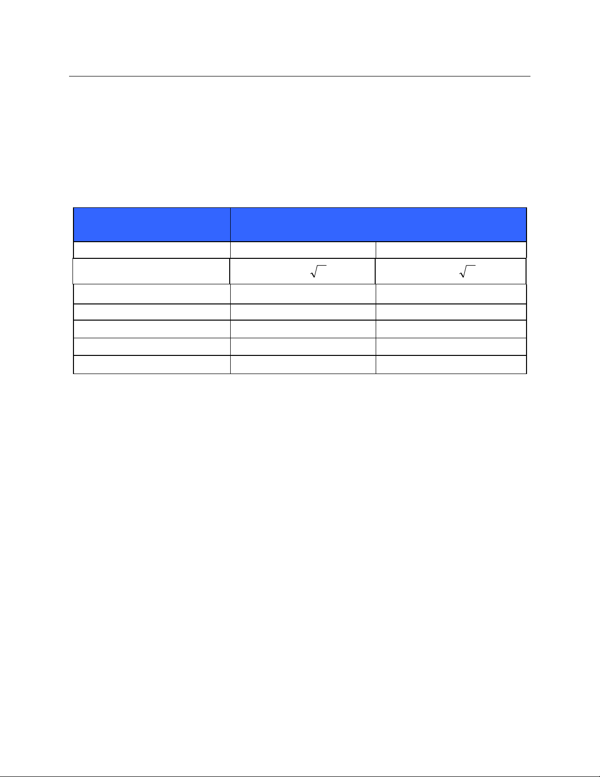
The following table shows the radio channels allocated in different geographic areas in the world. For bands
802.11b and g, only channels 1, 6, 11 and 14 (Japan only) are non-overlapping; for band 802-11a, channels
shown represent non-overlapping channel numbers.
Band Typical Power Region Frequency
Range (GHz)
15 dBm / 32 mW USA/Can ad a 2.401 - 2.473 11
802.11b
13 dBm / 18 mW USA/Can ad a 2.401 - 2.473 11
802.11g
17 dBm / 50 mW USA/Canada 5.15 - 5.35,
802.11a
Europe 2.401 - 2.483 13
Japan 2.401 - 2.495 14
Europe 2.401 - 2.483 13
Japan 2.401 - 2.483 13
5.725 - 5.825
Europe 5.15 - 5.35,
5.47 - 5.725
Japan 4.91 – 4.99,
5.15 - 5.35,
5.47 - 5.725
China 5.725 - 5.825 5
No. of
channels
13 36,40,44,48,52,56,60,64,149,
19 36,40,44,48,52,56,60,64,100,
23 36,40,44,48,52,56,60,64,100,
Channel numbers
1 – 11
1 – 13
1 – 14
1 – 11
1 – 13
1 – 13
153,157,161,165
104,108,112,116,120,124,
128,132,136,140
104,108,112,116,120,124,
128,132,136,140,184188,
192,196
149,153,157,161,165
8

USER SAFETY INFORMATION
The following table lists the frequency allocated for each channel used by the WLAN option.
Channel Center Frequency Frequency Spread
1 2412 MHz 2399.5 MHz - 2424.5 MHz
2 2417 MHz 2404.5 MHz - 2429.5 MHz
3 2422 MHz 2409.5 MHz - 2434.5 MHz
4 2427 MHz 2414.5 MHz - 2439.5 MHz
5 2432 MHz 2419.5 MHz - 2444.5 MHz
6 2437 MHz 2424.5 MHz - 2449.5 MHz
7 2442 MHz 2429.5 MHz - 2454.5 MHz
8 2447 MHz 2434.5 MHz - 2459.5 MHz
9 2452 MHz 2439.5 MHz - 2464.5 MHz
10 2457 MHz 2444.5 MHz - 2469.5 MHz
11 2462 MHz 2449.5 MHz - 2474.5 MHz
12 2467 MHz 2454.5 MHz - 2479.5 MHz
13 2472 MHz 2459.5 MHz - 2484.5 MHz
14 2484 MHz 2471.5 MHz – 2496.5 MHz
In order to achieve the best transmission rate, it is necessary that the facility where the device is operated can
provide good area coverage. Please consult the IT personnel of the facility to verify the proper WLAN
availability in the area where the device will be used.
RF wave propagation may be blocked or reduced by the environment where the device is used. Most common
areas where this may occur are: shielded rooms, elevators, underground rooms. In all the above situations, it is
recommended to move the device to a proper location and verify with the IT personnel of the facility the areas
where the WLAN signals are available.
9

USER SAFETY INFORMATION
10
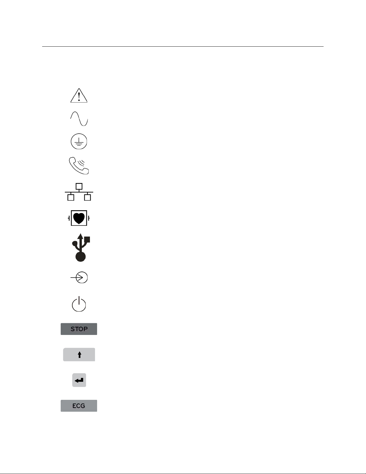
EQUIPMENT SYMBOLS AND MARKINGS
Symbol Delineation
Attention, consult accompanying documents
Alternating current
Protective earth
Telephone line (modem)
Network (LAN)
Defibrillator-proof type CF applied part
USB port
Input
ON/OFF (power)
Stop (of action)
Shift key (to enter upper case text)
Enter key (accept data/return)
Initiate printing of 12-lead ECG
11
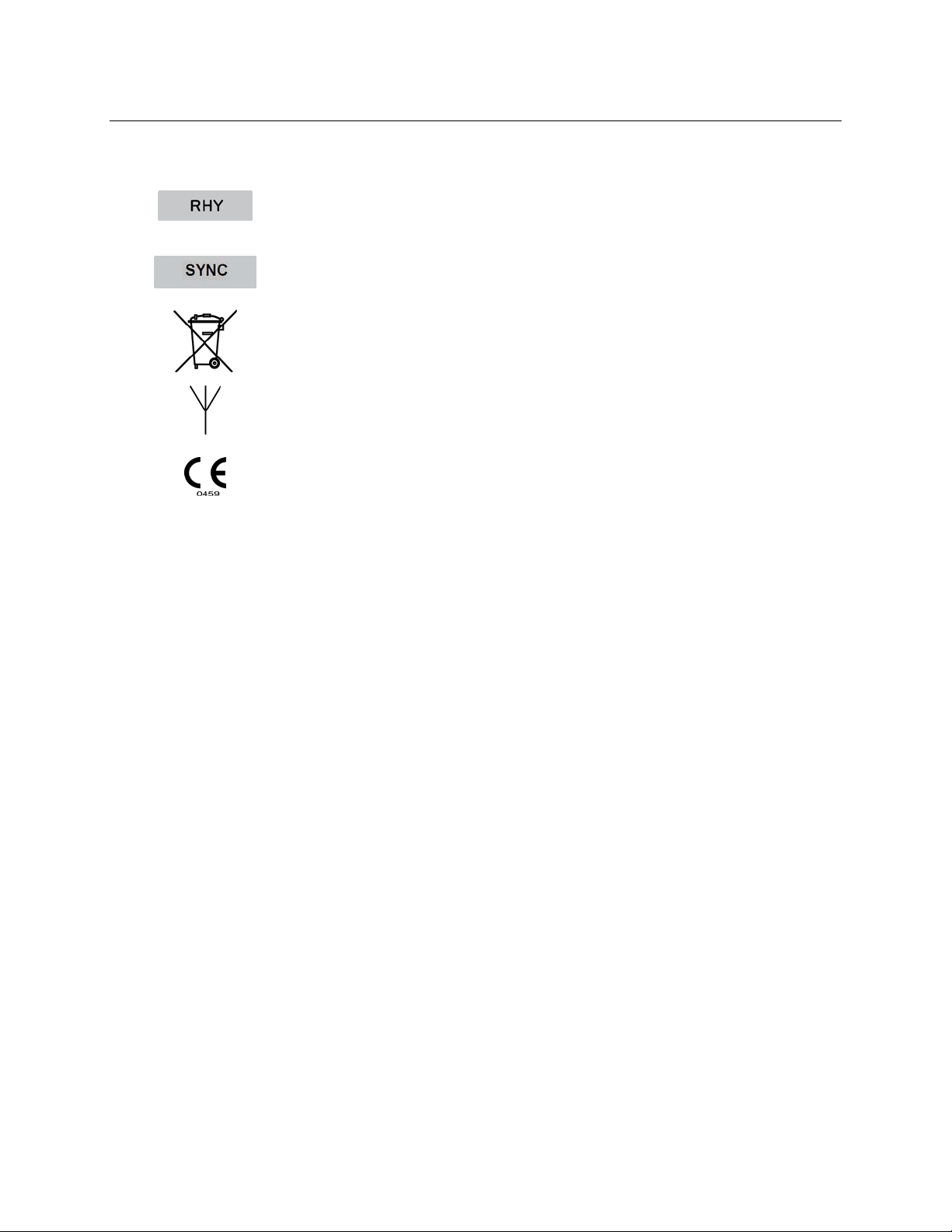
EQUIPMENT SYMBOLS AND MARKINGS
Initiate printing of continuous rhythm strip
Transmit, receive and time sync operation depending upon configuration
settings
Do not dispose as unsorted municipal waste. Per European Union
Directive 2002/96, requires separate handling for waste disposal according
to national requirements
Antenna
Indicates compliance to applicable European Union directives
12

ELECTROMAGNETIC COMPATIBILITY (EMC)
Electromagnetic compatibility with surrounding devices should be assessed when using the device.
An electronic device can either generate or receive electromagnetic interference. Testing for electromagnetic
compatibility (EMC) has been performed on the device according to the international standard for EMC for medical
devices (IEC 60601-1-2). This IEC standard has been adopted in Europe as the European Norm (EN 60601-1-2).
The device should not be used adjacent to, or stacked on top of other equipment. If the device must be used adjacent
to or stacked on top of other equipment, verify that the device operates in an acceptable manner in the configuration
in which it will be used.
Fixed, portable, and mobile radio frequency communications equipment can affect the performance of medical
equipment. See the appropriate table for recommended separation distances between the radio equipment and the
device.
The use of accessories, transducers, and cables other than those specified by Mortara Instrument may result in
increased emissions or decreased immunity of the equipment.
13

ELECTROMAGNETIC COMPATIBILITY (EMC)
Guidance and Manufacturer’s Declaration: Electromagnetic Emissions
The equipment is intended for use in the electromagnetic environment specified in the table below. The customer or
the user of the equipment should ensure that it is used in such an environment.
Emissions Test Compliance Electromagnetic Environment: Guidance
RF Emissions CISPR 11 Group 1 The equipment uses RF energy only for its internal function.
Therefore, its RF emissions are very low and not likely to cause
any interference in nearby electronic equipment.
RF Emissions CISPR 11 Class A The equipment is suitable for use in all establishments other
than domestic and those directly connected to the public lowvoltage power supply network that supplies buildings used for
Harmonic Emissions
IEC 61000-3-2
Complies
domestic purposes.
Voltage Fluctuations/
Flicker Emissions
IEC 61000-3-3
Complies
Guidance and Manufacturer’s Declaration: Electromagnetic Immunity
The equipment is intended for use in the electromagnetic environment specified in the table below. The customer or
the user of the equipment should ensure that it is used in such an environment.
Emissions Test Compliance Compliance Level Electromag n etic Environment: Guidance
Electrostatic
discharge (ESD)
IEC 61000-4-2
Electrical fast
transient/burst
IEC 61000-4-4
Surge
IEC 61000-4-5
Voltage dips,
short
interruptions,
and voltage
variations on
power supply
input lines
IEC 61000-4-11
Power frequency
(50/60 Hz)
magnetic field
+/- 6 kV contact
+/- 8 kV air
+/- 2 kV for
power supply lines
+/- 1 kV for
input/output lines
+/- 1 kV differential
mode
+/- 2 kV common
mode
<5% UT
(>95% dip in UT)
for 0.5 cycle
40% UT
(60% dip in UT)
for 5 cycles
3 A/m 3 A/m Power frequency magnetic fields should be at
+/- 6 kV contact
+/- 8 kV air
+/- 2 kV for
power supply lines
+/- 1 kV for
input/output lines
+/- 1 kV differential
mode
+/- 2 kV common
mode
<5% UT
(>95% dip in UT)
for 0.5 cycle
40% UT
(60% dip in UT)
for 5 cycles
Floors should be wood, concrete, or ceramic
tile. If floors are covered with synthetic
material, the relative humidity should be at
least 30%.
Mains power quality should be that of a typical
commercial or hospital environment.
Mains power quality should be that of a typical
commercial or hospital environment.
Mains power quality should be that of a typical
commercial or hospital environment.
levels characteristic of a typical location in a
typical commercial or hospital environment.
NOTE: UT is the AC Mains voltage prior to application of the test level.
14
ELECTROMAGNETIC COMPATIBILITY (EMC)
Guidance and Manufacturer’s Declaration: Electromagnetic Immunity
The equipment is intended for use in the electromagnetic environment specified in the table below. The customer or
the user of the equipment should ensure that it is used in such an environment.
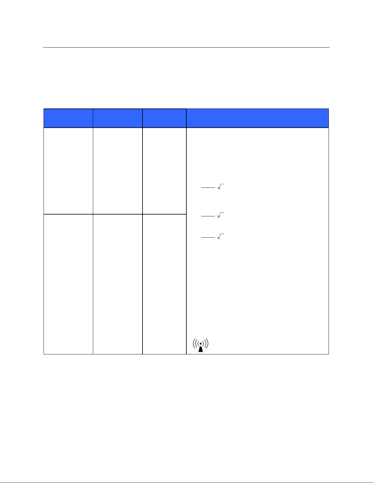
Emissions Test
IEC 60601 Test
Level
Compliance
Level
Electromagnetic Environment: Guidance
Conducted RF
IEC 61000-4-6
Radiated RF
IEC 61000-4-3
3 Vrms
150 kHz to
80 MHz
3 V/m
80 MHz to
2.5 GHz
3 Vrms
150 kHz to
80 MHz
3 V/m
80 MHz to
2.5 GHz
Portable and mobile RF communications equipment
should be used no closer to any part of the equipment,
including cables, than the recommended separation
distance calculated from the equation applicable to the
frequency of the transmitter.
Recommended separation distance
5.3
d
Vrms
3
P
5.3
d
80 MHz to 800 MHz
P
mV
/3
7
d
Where P is the maximum output power rating of the
transmitter in watts (W) according to the transmitter
manufacturer and d is the recommended separation
distance in meters (m).
Field strengths from fixed RF transmitters, as
determined by an electromagnetic site surveya, should
be less than the compliance level in each frequency
b
range
.
Interference may occur in the vicinity of equipment
marked with the following symbol:
800 MHz to 2.5 GHz
P
mV
/3
a. Field strengths from fixed transmitters, such as base stations for radio (cellular/cordless) telephones and land mobile radios,
amateur radios, AM and FM radio broadcast, and TV broadcast cannot be predicted theoretically with accuracy. To assess
the electromagnetic environment due to fixed RF transmitters, an electromagnetic site survey should be considered. If the
measured field strength in the location in which the equipment is used exceeds the applicable RF compliance level above, the
equipment should be observed to verify normal operation. If abnormal performance is observed, additional measures may be
necessary, such as reorienting or relocating the equipment.
b. Over the frequency range 150 kHz to 80 MHz, field strengths should be less than [3] V/m.
15
ELECTROMAGNETIC COMPATIBILITY (EMC)
Recommended Separation Distances Between Portable and Mobile RF Communications
Equipment and the Equipment
The equipment is intended for use in the electromagnetic environment in which radiated RF disturbances are
controlled. The customer or the user of the equipment can help to prevent electromagnetic interference by
maintaining a minimum distance between portable and mobile RF communications equipment (transmitters) and the
equipment as recommended in the table below, according to the maximum output power of the communications
equipment.
Rated Maximum Output Power
of Transmitter W
150 KHz to 800 MHz 800 MHz to 2.5 GHz
Separation Distance According to Frequency of Transmitter (m)
0.01 0.1 m 0.2 m
0.1 0.4 m 0.7 m
1 1.2 m 2.3 m
10 4.0 m 7.0 m
100 12.0 m 23.0 m
Pd 2.1
Pd 3.2
For transmitters rated at a maximum output power not listed above, the recommended separation distance d in
meters (m) can be estimated using the equation applicable to the frequency of the transmitter, where P is the
maximum output power rating of the transmitter in watts (W) according to the transmitter manufacturer.
NOTE 1: At 800 MHz, the separation distance for the higher frequency range applies.
NOTE 2: These guidelines may not apply in all situations. Electromagnetic propagation is affected by the
absorption and reflection from structures , o bj ect s, an d pe o pl e.
16

MAINTENANCE & CLEANING
SECTION 2
Preventive Maintenance
Preventive maintenance is recommended to be performed on the ELI150c/250c once every 12
months.
Warning: Preventive maintenance is to be performed by Mortara authorized service personnel
only.
2.0 Maintenance Procedure
2.1 Turn unit on and print the device configuration per section 3 of this manual. Attach a
copy to the Preventive Maintenance Report.
2.2 Remove the unit cover per section 4 of this manual.
2.3 Perform a visual inspection of the following items:
2.3.1 Enclosure/Housing – Look for damage or cracks in the external housing or
enclosure that could possibly expose the device to the introduction of foreign
objects or fluids. Attention should also be paid to areas that could expose an
operator or patient to internal circuitry of the device.
2.3.2 Contamination – Look for any contamination that may have occurred over time
that could not be seen with the housing in place.
Fluid damage (perhaps caused during device cleaning)
Debris on or behind display shield
Battery leakage (lithium and main battery)
2.3.3 Internal Cabling – Look for cracked, pinched or partially disconnected cable
connections.
2.3.4 Fuse Ratings – Verify PCB mounted fuses (items 23 and 24) the meet the
specifications defined in the item description listing.
2.3.5 Markings and Labeling – Verify all labels and device markings are clearly visible
and legible to the device user and have not been worn off or rendered
unreadable through the use of harsh cleaning agents.
2.3.6 Integrity of Mechanical Parts – Verify the following items are properly secured to
the device and have not become loose or damaged through usage over time.
AC Inlet
Patient Input Connector
Communication ports and antenna
Writer mechanics/latching mechanism
2.4 Power Testing
* Based upon customer usage and age of battery, replace as needed.
2.4.1 Ensure battery is fully charged before performing these tests, voltage and current
limits are based on a fully charged battery.
2.4.2 Ensure there is no power connected to the UUT AC inlet.
2.4.3 Remove upper housing and writer assembly. Disconnect battery by pulling
battery cable off of the red terminal.
17

SECTION 2
2.4.4 Note battery age (if possible)
This information can be found on the white “date code” sticker located on the
battery (use the earliest date that is not crossed out).
2.4.5 Battery (open circuit)
Measure battery voltage using a voltage meter; verify the meter reads greater
than 12.5vdc.
2.4.6 Battery (load)
Measure the battery voltage using a volt meter and a power resistor load
(10ohm, 20watt) in parallel with the battery. After approximately 5 seconds,
verify the meter reads greater than 11.7vdc.
2.4.7 Off current
Connect a current meter in line with battery. With the UUT power off, verify the
current meter reads less than 100 micro amps.
2.4.8 On current
Turn on the unit and verify the current meter reads less than 250 milli amps.
2.4.9 AC charging current
Apply AC power to the unit and verify that the current draw from the battery
reverses polarity and the value starts decreasing as time increases.
2.4.10 Battery charger output voltage
Disconnect the current meter and measure the battery charger output voltage
between the red disconnected battery cable and the negative terminal on the
battery. It should read between 13.0vdc and 14.0vdc.
2.5 Verify all power cables are reconnected properly
2.6 Reassemble unit in reverse order of disassembly
2.7 Functional Testing
2.7.1 AC LED/Display
Connect AC power cord to the unit and verify that the green AC LED (located to
the left of the display) illuminates continuous.
NOTE: The battery indicator will be clear when charging and will illuminate white
when fully charged.
Verify text on display is clear and legible and there are no flickering or missing
lines/pixels.
2.7.2 Writer
Open and close the writer door to verify smooth operation. Verify that the door
unlatches without sticking and that it latches completely. From the main screen,
simultaneously press shift+alt+RHY. Verify that a test page is printed and the
writer stops on the cue mark. The perforation of the paper should line up with the
tear edge on the writer. Assure there are no gaps in the printing and the print
darkness is uniform across the entire page. Verify the writer gears do not skip
and paper is tracking properly (you may need to print multiple pages to observe
this).
18

SECTION 2
2.7.3 ECG & Keyboard Matrix
Connect an ECG simulator to the AM12 or WAM patient interface. Set the
simulator to a known heart rate and amplitude; preferably to a setting that you
have a “known good” printout for comparison. Press the ECG key to capture an
ECG. Verify there is an audible beep with each key press. Enter Last name
“PARCFL8” (Note: “PARCFL8” ensures the keyboard matrix is fully tested), then
press F6 (Done). Verify that 12 ECG traces print correctly and assess the
printout quality. Ensure uniform darkness across entire printout.
2.7.4 ECG Noise Test
Connect a Shorting Block (TF-0063) and adapter or equivalent to the AM12 or
WAM patient interface. Set the ECG gain on the unit to 20mm/mV. Print a
rhythm strip (approx. 1 page). Verify that no channels have more than 0.5mm of
noise.
2.7.5 Communication options
Verify successful transmission of all applicable communication options by
transmitting the ECG record stored in step 2.7.3 to a compatible receiving device:
Modem
LAN
WLAN
GSM/GPRS
USB
USBD
2.8 Clean unit per the instructions provided on the following page of this section of the service
manual.
2.9 Safety Testing
The following safety tests should be performed in accordance with all local regulatory
requirements:
Earth Leakage
Enclosure Leakage
Patient Leakage
Patient Auxiliary Current
19

SECTION 2
Device Cleaning & Disinfecting
Warning:
Use of non-recommended cleaning agents or practices could cause damage to the device or
possible compromising of the electrical isolation of the device.
Makes sure all cables and accessories a re disconnected from the device prior to performing
cleaning process.
Do not immerse the device in liquid.
Do not use organic solvents, ammonia-based solutions, or abrasive cleaning agents that may
damage equipment surfaces.
Do not use excessive amounts of liquid during cleaning or di sinfecting of the device, as these
fluids could enter the device housing and cause damage to the device.
Recommended Supplies:
Clean lint free cloth
Mild detergent
Luke warm water
10% Household bleach and water solution (Sodium Hypochlorite solution consisting of a
minimum 1:500 dilution and maximum of 1:10 dilution for disinfecting use only)
Device Cleaning:
Disconnect the AC power cord from the device. Clean the exterior surface of the device with a damp (not
wet), soft, lint-free cloth using a solution of mild detergent diluted in luke warm water. After cleaning,
thoroughly dry off the device with a clean, soft cloth or paper towel.
Device Disinfecting:
Clean the device per the instructions defined above, then wipe the exterior of the device with a damp (not
wet), soft, lint-free cloth using a solution of 10% bleach and water. Allow the device to air dry after
disinfecting before returning to use.
20

Mortara Instrument, Inc. Phone (414) 354-1600
7865 N. 86
Milwaukee, WI. 53224
th
Street Fax (414) 354-4760
Mortara Instrument Inc.
ELI 150/250c Preventive Maintenance Report
Unit Serial #: _________________________________________
□ Print device configuration (attach to this report)
□ Remove the units upper housing
□ Perform Visual Inspection
□ Enclosure/Housing
□ Contamination
□ Cabling
□ Fuse Ratings
□ Markings and Labeling
□ Integrity of Mechanically Parts
□ Power Testing
□ Note Battery Age (If Possible) _____/_____ (week/year)
□ Battery (Open Circuit) Voltage _______ VDC
□ Battery (with Load) Voltage _______ VDC
□ Off Current _______ uA
□ On Current _______ A
□ Battery Charger Output Voltage _______ VDC
* Based upon customer usage and age of main battery, replace as needed.
□ Verify all power cables are properly reconnected and reassemble unit
□ Functional testing
□ AC LED/Display Functionality
□ Writer Test
□ ECG & Keyboard Matrix Testing
□ ECG Noise Test
□ Communication Options
□ Device Cleaning
□ Safety Testing PASS / FAIL (circle)
□ Earth Leakage
□ Enclosure Leakage
□ Patient Leakage
□ Patient Auxiliary Current
Technician or Field Service Engineer: ____________________________ Date: _____/_____/_____
21

22

DEVICE CONFIGURATION
SECTION 3
Setting Technician Password
1. From real-time ECG view, select F6 (More) followed by F5 (Set Time/Date).
2. While holding down
3. If required, enter password. This will automatically advance you to the set passwords display.
NOTE: The factory default password is “admin” (lowercase, no quotation marks); it is
suggested that the password be changed after installation of the unit.
4. Enter a technician password followed by a second entry to confirm.
NOTE: Password is case sensitive and alphanumeric.
5. From this display, select F6 (Exit) to return to real-time ECG view.
Configuration Menus
The configuration pages define all operational conditions that do not change on a daily or patient-to-patient basis.
Once you set these default conditions, you will rarely need to use the configuration screens again. To access the
configuration menus:
1. From real-time ECG view, select F6 (More) followed by F5 (Set Time/Date).
2. While holding down
3. If required, enter password. The first configuration screen will appear. Notice the page indicator in the
upper right-hand corner.
To navigate the configuration menus:
Use F4 (Page) to toggle through the configuration pages.
Use F1 (▲) and F2 (▼) to move back and forth through each configuration option.
Use F3 (►) to toggle through pre-programmed available settings per configuration field.
Use F6 (Exit) to return to real-time ECG view. Any changes you have made will be saved.
Use BKSP to erase entry errors.
To print the device’s configuration settings, select F6 (More) from real-time ECG view. Select F6 (More) again
followed by F1 (Print Configuration). The configuration printout captures every configuration setting: the
software version, the cart number of the device, and the date and time that the configuration printout occurred.
(SHIFT), depress ALT and P simultaneously.
(SHIFT), depress ALT and C simultaneously .
23

Summary of Configuration Menus
Configuration Parameter Definition
Software Version Displays software version on printout and display
Cart Number Numeric field 0 to 65535
Site Number Numeric field 0 to 4095
Site Name Alphanumerical field (30 digits)
Telephone Number Alphanumerical field (45 digits)
Language Available software languages
Volume Numerical field 0 to 8
Battery Timeout 10 min, 30 min, 60 min
Flash Size Normal or expanded (optional)
ID Format Standard, Short, Long, Custom
Auto-Fill ID YES/NO
SECTION 3
AC Filter 50 Hz, 60 Hz, None
Paper Speed 25 or 50 mm/sec
Filter Frequency response for printouts: 40 Hz, 150 Hz, 300 Hz
Height/Weight Units lb/in or kg/cm
Date Format US (mm/dd/yyyy) or European (dd.mm.yyyy)
Interpretation YES/NO
Reasons YES/NO
Append Unconfirmed Report, Reviewed by
# of Copies 0 – 9
Copies with Interp. YES/NO
# ECGs Retrieved 0 – 7
Delete Rule Post Plot, Post Transmit, Post Plot/Xmt
Storage Sensitivity Normal or High
Auto-Save ECG YES/NO
Auto-Print ECG YES/NO
Cap Lock YES/NO
Use A4 paper
(ELI 250c only)
Rhythm Format 3 or 6 channel (ELI 150c); 3, 6, or 12 channel (ELI 250c)
3 Rhythm Lead 1 V1-V6, I, II, III, aVR, aVL, aVF
3 Rhythm Lead 2 V1-V6, I, II, III, aVR, aVL, aVF
3 Rhythm Lead 3 V1-V6, I, II, III, aVR, aVL, aVF
6 Rhythm Lead 1 V1-V6, I, II, III, aVR, aVL, aVF
YES/NO
24

Summary of Configuration Menus (continued)
Configuration Parameter Definition
6 Rhythm Lead 2 V1-V6, I, II, III, aVR, aVL, aVF
6 Rhythm Lead 3 V1-V6, I, II, III, aVR, aVL, aVF
6 Rhythm Lead 4 V1-V6, I, II, III, aVR, aVL, aVF
6 Rhythm Lead 5 V1-V6, I, II, III, aVR, aVL, aVF
6 Rhythm Lead 6 V1-V6, I, II, III, aVR, aVL, aVF
Plot Format
3+1 Rhythm Lead V1-V6, I, II, III, aVR, aVL, aVF
3+3 Rhythm Lead 1 V1-V6, I, II, III, aVR, aVL, aVF
3+3 Rhythm Lead 2 V1-V6, I, II, III, aVR, aVL, aVF
3+3 Rhythm Lead 3 V1-V6, I, II, III, aVR, aVL, aVF
Bar Code Scanner YES/NO
Avg RR YES/NO
3, 3+1, 3+3, 6 channel; Cabrera or standard (ELI 150c)
3+1, 3+3, 6, 6+6, 12 channel; Cabrera or standard (ELI 250c)
SECTION 3
QTcB YES/NO
QTcF YES/NO
ECG Capture Last 10 or Best 10
Band Mode
(GSM/GPRS only)
(ELI 150c only)
Sync Media
DHCP
(active for LAN or WLAN)
IP Address
(active for LAN or WLAN)
Def Gateway
(active for LAN or WLAN)
Sub Net Mask
(active for LAN or WLAN)
Host IP
(active for LAN or WLAN)
Port Number
(active for LAN or WLAN)
Security
LAN MAC XX XX XX XX XX XX
850/1900MHz (US) or 900/1800MHz(EU)
None, Modem, LAN, WLAN, GSM/GPRS
(GSM/GPRS option applies to ELI 150c only)
YES/NO
XXX.XXX.XXX.XXX
XXX.XXX.XXX.XXX
XXX.XXX.XXX.XXX
XXX.XXX.XXX.XXX
Numeric field (9 digits)
None, WEP128, WEP64, WPA-PSK, WPA-LEAP, WPA-PSK64, WPA-PSK128,
WPA-LEAP 64, WPA-LEAP128, WPA2-PSK, WPA2-PEAP
WLAN MAC XXXXXXXXXXXX
SSID Alphanumerical field (30 digits) (not on printout)
25

Summary of Configuration Menus (continued)
Configuration Parameter Definition
WEP Key Numeric (1 digit) (not on printout); valid range 1-4
WEP Key ID Alphanumerical field (26 digits) A-F, 0-9 (not on printout)
PSK Passphrase Alphanumeric field (64 digits) (not on printout)
LEAP User Name Alphanumeric field (32 digits) (not on printout)
LEAP Password Alphanumeric field (32 digits) (not on printout)
PEAP User Name Alphanumeric field (63 digits) (not on printout )
PEAP Password Alphanumeric field (63 digits) (not on printout)
Worklist Management Standard or Refresh
Comm Protocol UNIPRO32, DICOM32, DICOM32ext OR UNIPRO64, DICOM64 (V2.x software)
Sync Mode None, XMT, XMT+Orders
Sync Date/Time YES/NO
XMT Mandatory Fields None, Last Name, ID, Last Name+ID
SECTION 3
26

SECTION 3
Configuration Settings
Software Version
Identifies the software version of your electrocardiograph.
Cart Number
Indicates which electrocardiograph acquired or transmitted a particular ECG.
Site Number
Identifies the site of your device. Site numbers designate the hospital, clinic, or institution for ECG records stored in
an E-Scribe system and must be defined for transmitting and retrieving ECGs from that system. You can use up to
four digits for the site number. Numbers from 0 – 4095 are supported.
Site Name
Defines your clinic, hospital, or office name. You can enter up to 30 alphanumeric characters. The site name prints
at the bottom, left edge of the ECG printout.
Telephone Number
Specifies the telephone number for internal modem transmission to another unit or to an E-Scribe system. Enter up
to 45 numeric characters.
You may need to dial a 9 to get an outside line. To wait for an additional dial tone, use the letter W.
EXAMPLE: 9W14145554321
To insert a pause, use a comma (,).
To change tone dialing to pulse dialing, use the letter P.
EXAMPLE: P14145554321
(If necessary, you can use both the letter W and the letter P in the same phone number.)
NOTE: It is not necessary to use alpha characters in the telephone number with GSM/GPRS mobile
connectivity.
TIP: To quickly delete or modify a phone number, use a shortcut. From the applicatio n screen,
simultaneously press (SHIFT) + ALT + P. To edit an existing telephone number, use the Tab key.
Language
There are several lang uages available on the electrocardiograph.
CAUTION: Function labels are immediately translated upon selecting a new language and exiting the
configuration screen.
27

SECTION 3
If an unknown language is visible, use the following steps to revert to the language of your country:
1. F6 (More) from real-time ECG view.
2. Select F5 (Set Time/Date).
3. Simultaneously press (SHIFT) + ALT + C.
4. Enter password (“admin”)
5. Press F2 (▼) four times.
6. Press F3 (►) until the desired language appears.
7. F6 (Exit) to return to real-time ECG view.
Alphabets of specific languages may require use of special characters in demographic fields. This is accomplished
by using the SYM key on the keyboard.
Volume
Defines the keyboard click loudness. Available settings range from 0 (off) to 8 (loud).
Battery Time Out
Determines when the electrocardiograph will switch off in order to conserve the battery life of the device. The
battery time out will only occur if the keyboard has not been depressed for the time specified. The battery time out
setting is ignored if an active ECG signal is detected during transmission or while rhythm printing.
Flash Size
Indicates ECG storage capacity. Normal indicates standard memory capacity. Expanded indicates the optional
expanded memory has been installed.
ID Format
Defines the format for the patient demographic information prompts. There are three standard formats: short,
standard, or long. A custom ID format can be downloaded from ELI Link or an E-Scribe system. See Appendix A
to download a custom ID.
The short format includes the patient's last and first name, patient ID number, date of birth (automatically calculates
the age), and gender.
The standard format includes the patient's last name, patient ID number, age, height, weight, gender, race,
medication 1, medication 2, and a location field.
The long format is identical to the standard format except that it includes the patient's first name, room, and
comment fields.
Auto-Fill ID
When enabled, the device will automatically populate last name, first name, date of birth, age, and gender in the ID
screen if records with matching patient ID are found in the ECG directory.
28

SECTION 3
AC Filter
The device removes 60 Hz or 50 Hz interference. The setting you select depends on the line frequency in your
country. Always use the 60 Hz setting in the U.S. If AC interference is present, check to see that the proper AC
filter is selected.
Paper Speed
Configure to 25 mm/s or 50 mm/s for default ECG printouts. For rhythm printouts and display, speeds of 5 mm/s or
10 mm/s are also available. See Section 3 to change speeds for display or rhythm printing. Paper speed is printed at
the bottom right corner of the ECG printout.
Filter
The ECG plot-frequency filter (or print filter) can be set to 0.05 to 40 Hz, 0.05 to 150 Hz, or 0.05 to 300 Hz. The
plot-frequency filter does not filter the acquired digital record. A 40 Hz plot-filter setting will reduce the noise
(40 Hz and higher frequencies) on the printed ECG, and a 150 Hz plot-filter setting will reduce the noise (150 Hz
and higher frequencies) on the printout; a 300 Hz plot-filter setting will not filter the printed ECG. The filter setting
is printed at the bottom right corner of the ECG printout.
Height/Weight Units
Defines the units of weight and height to either pounds/inches (lb/in) or kilograms/centimeters (kg/cm).
Date Format
Select either U.S. or European format for enteri ng and disp l ay i ng the patient’s date of birth.
U.S. Date Format: MM/DD/YYYY
European Date Format: DD.MM.YYYY
NOTE: The date format option does not modify the acqui sition date printed on each ECG.
Interpretation
The device automatically analyzes ECGs and prints the optional interpretation on the ECG printout. This setting
allows you to select or suppress the “interpretive” text on the ECG report.
NOTE: The ECG interpretations offered by the device are only significant when used in conjunction with
a physician over-read as well as consideration of all other relevant patient data.
Reasons
The reasons statements indicate why a particular interpretive statement was printed. Reasons statements print
enclosed in [square brackets] within the interpretive text if the interpretation option is turned on. Turning the
reasons statement function on or off does not affect the measurements performed or the interpretive statements
selected by the analysis program.
For Example:
Anteroseptal Infarct [40+ ms Q WAVE IN V1-V4]
Where “Anteroseptal Infarct” is the interpretive statement,
and “40+ ms Q WAVE IN V1-V4” is the reason statement or explanation as to why the
interpretive statement was printed.
29

SECTION 3
Append
A status or statement phrase can be appended to the ECG and printed under the interpretive text printout. Either
“unconfirmed report” or “reviewed by” can be selected; however, if you wish to have nothing appended to the ECG,
select “blank”.
Number of Copies
Defines the number of printed copies when an ECG is taken. A zero (0) setting prints the original only; one (1)
prints the original plus 1 copy; two (2) prints the original plus 2 copies, and so on. Up to 9 copies may be selected.
Copies with Interpretation
Defines whether or not printed copies will include interpretation. The clinician may request the first ECG printout
with the interpretation included. Additional copies may be printed with or without the interpretation.
Number of ECGs Retrieved
Defines the number of ECGs retrieved from an E-Scribe system. The ECGs are retrieved by ID number. A zero (0)
setting retrieves the most current ECG for that ID number. Settings from one (1) to seven (7) retrieve the most
current ECG plus “X” number of ECGs identified by the entered value. EXAMPLE: If you enter the number 5, you
will retrieve the most current ECG plus the five preceding ECGs for that ID number. ECGs retrieved from the
E-Scribe are only printed at the device and not saved.
Delete Rule
Defines the rule to mark ECGs as deleted in the ECG directory. ECGs that are marked for deletion will be
automatically removed or erased based on their acquisition date (a first-in/first-out philosophy) to make room for the
new ECG record. ECGs are only erased from the directory when they are marked for deletion and if the directory
becomes full. More than one ECG may be removed from the directory in order to make room for the new incoming
record. The delete rule selections are:
Post Plot = ECG is automatically marked for deletion after printing
Post Transmit = ECG is automatically marked for deletion after transmission
Post Plot/Transmit = ECG is automatically marked for deletion after transmission and printing
Storage Sensitivity
Dictates the resolution of all stored ECG records. The sensitivity setting is either Normal or High. If the value is set
to High, the stored ECG will have a high resolution. As a result, the record size will be large and will reduce the
storage capacity in the ECG directory.
Auto-Save ECG
Defines whether or not a newly acquired ECG will be automatically saved to the directory once it is acquired and
printed. If the auto-save configuration option is set to No and the record is printed, the device will prompt you to
“Save ECG?” F1 (Save) will store the ECG in the directory.
Auto-Print ECG
Defines whether or not the device will automatically print the ECG after acquisition . If the selected configuration
option is set to No, a manual printout is possible.
30

SECTION 3
Caps Lock
All character entry is translated to uppercase.
Use A4 Paper
The ELI 250c accommodates use of Z-fold thermal paper in either letter size (8.5 x 11 inches; 216 x 279 mm) or A4
size (8.27 x 11.69 inches; 210 x 297 mm). The provided paper tray spacer is required for use with A4 size paper.
Rhythm Formats
Defines the default values for rhythm printing. It is possible to set a 3 or 6-channel default rhythm format for the
ELI 150c. For the ELI 250c, a 3, 6, or 12-channel default r hy t hm format is possible. Define rhythm leads one
through three to customize a 3-channel rhythm printout or define rhythm leads one through six to customize the
6-channel rhythm printout .
Plot Format
Defines the default for one of the available plot formats in either standard or Cabrera presentation. Please note that
regardless of the plot format selected, 10 seconds of 12 leads are always stored.
The ECG plot options are:
Format Option ECG Data
2.5 seconds of 12 leads in a 3-channel format, plus 10second rhythm strip of one user-selectable lead in a 1-
3+1
3
(ELI 150c only)
6
3+3
12
(ELI 250c only)
6+6
(ELI 250c only)
channel format.
Cabrera also available.
2.5 seconds of 12 leads in a 3-channel format.
Cabrera also available.
5 seconds of 12-leads in a 6-channel format.
Cabrera also available.
2.5 seconds of 12 leads in a 3-channel format, plus 10second rhythm strip of user-selectable leads in a 3channel format.
Cabrera also available.
10 seconds of 12 leads in a one page printout.
5 seconds of 6 leads in a 6-channel format, plus 10second rhythm strip of user-selectable leads in a 6channel format.
Cabrera also available.
31

SECTION 3
Rhythm Leads
Displays continuous rhythm of selected ECG leads and permits printing of selected leads. User may toggle between
selected leads, system set leads, or I, II, III, aVR, aVL, and aVF followed by V1, V2, V3, V4, V5, and V6.
NOTE: Rhythm acquisition is not stored in memory, only printed.
NOTE: See Section 3 to acquire a rhythm printout.
Average RR
Enabling this option will display an averaged RR value to appear on the report.
QTcB
Enabling this option will display a Bazett’s corrected QT value on the report along with the default linear
QTc value.
QTcF
Enabling this option will display a Fridericia corrected QT value on the report along with the default linear
QTc value.
ECG Capture
Up to 5 minutes accumulated ECG data can be acquired internally for use with the Best 10 feature. The device
automatically selects the best 10 seconds from within the 5-minute buffer.
Users can switch between BEST 10 or LAST 10 by selecting F5 (More) followed by F5 (Last) or F5 (Best)
depending on the current view.
Band Mode
Use 850/1900 MHz (US) or 900/1800 MHz (EU). (Applies to ELI 150c only.)
Sync Media
Defines the default transmission setting. Select None, Modem, LAN, WLAN, or GSM/GPRS (GSM/GPRS option
applies to ELI 150c only). Optional connectivity options which have been purchased and installed will be available
for default selection.
An ELI x50c communicating over GPRS can be configured to automatically set its clock to match the time on a time
sync server. The time sync server must return a time stamp in the ELI x50c’s local time zone via the daytime
protocol (RFC 867). The time sync server must have a public IP address, and the standard port is 13. The server
must return the time in one of the following formats:
Format 1
day mon dd HH:mm:ss yyyy
Example
Wed Jul 15 17:05:49 2010
32

SECTION 3
Format 2
hh.mm.ss tt mm/dd/yyyy
Example
02:38:51 PM 07/18/2011
Time sync servers running the Dimension 4 (http://www.thinkman.com/dimension4/index.htm
support Format 1.
DHCP
Defines whether the Dynamic Host Communication Protocol (DHCP) will be used to obtain an IP address. If DHCP
is Yes, the network will automatically and dynamically assign an IP address. If DHCP is No, you must enter the IP
address, def gateway, and sub net mask.
NOTE: All parameters related to network connection must be entered under the direction of the IT
Manager of the facility where the device is installed.
IP Address
Enter the fixed IP address for network transmissions (if DHCP is not selected).
Def Gateway
Enter the address of the default gateway (if DHCP is not selected).
Sub Net Mask
Enter the sub net address (if DHCP is not selected).
Host IP
Enter the IP address of the host server.
NOTE: Addresses are always entered as 4 sets of 3 digits; therefore , an ad dress of 19 2. 168. 0. 7 m ust b e
entered as 192.168.000.007.
Port Number
Enter the port number used by the host server.
LAN MAC
Shows the MAC address of the LAN.
Security (WEP)
Wired Equivalent Privacy (WEP) is an encrypted security prot ocol (part of the 802.11 standard). Access points can
have multiple WEP keys stored. Each one of them is identified by a number (e.g., 1, 2, 3, 4).
WEP Key
Enter the WEP key number.
) time sync software
33

SECTION 3
WEP Key ID
Enter the 128-bit WEP key ID value (26 digits in 13 sets of two digits).
WLAN MAC
Shows the MAC address of the device’s wireless module for configuring access points.
SSID
Service Set Identifier (SSID) is the name of the wireless network. All ELI 150c electrocardiographs that will
transmit to the same network must have the same SSID name. This field is case sensitive.
WPA-PSK/WPA2-PSK
Allows for implementation of the “personal mode” of WPA. This mode of encryption employs Temporal Key
Integrity Protocol (TKIP
PSK Passphrase
The passphrase may be from eight to 63 ASCII characters or 64 hexadecimal digits (256 bits).
WPA-LEAP
Cisco® LEAP (Light Extensible Authorization Protocol) enables use of the device with wireless networks
employing the LEAP encryption protocol.
LEAP User Name
User name can be up to 32 characters in length.
LEAP Password
LEAP password can contain up to 32 characters.
WPA2-PEAP
Enables use of the device with wireless networks employing the PEAP encryption protocol.
PEAP User Name
User name can be up to 63 characters in length.
PEAP Password
Password can contain up to 63 characters.
) which dynamically changes keys as the system is used.
34

SECTION 3
Worklist Management
The device can download and process ECG order lists from the E-Scribe or another compatible information
management system which identifies the ECGs (or ECG orders) needed for particular patients. Implementation of
an order-based workflow can significantly reduce demographic data entry errors at the electrocardiograph. Orders
are deleted from the list when the ordered ECG is acquired.
When set to Standard, new order lists are appended to the remaining list. When set to Refresh, each new order list
will override the previously downloaded one.
Comm. Protocol
Select UNIPRO32, DICOM32, OR DICOM32ext for software v1.x.x. DICOM32 and DICOM32ext are only
available if the DICOM option has been installed. Select UNIPRO64 OR DICOM64 FOR SOFTWARE V2.x.x.
DICOM64 is only available if the DICOM option has been installed.
NOTE: This parameter must be entered under the direction of the IT Manager of the facility where the
device is installed.
NOTE: Units ship by default with Comm Protocol set to UNIPRO32. The UNIPRO32 setting is not
supported by E-Scribe versions prior to V8.10 or ELI Link versions prior to V3.00. For questions about
compatibility of your device with E-Scribe or ELI Link and UNIPRO32, contact Mortara Technical
Support. Units shipped with v2.x.x software will not connect with E-Sc ribe and need Eli Link v4.0 or
above.
Sync Mode
Select None, XMT, or XMT+Orders. None requires a manual transmission of reports and then a second manual
request to receive orders from the cardiology management system. XMT will automatically transmit the report;
XMT+Orders will both transmit the report and retrieve the orders.
Sync Date/Time
Select Yes or No. Yes will synchronize the date/time with the approved cardiology management system. With No,
there will be no date/time synchronization. Date/time synchronization is done through ELI Link V3.10 or later.
XMT Mandatory Fields
Defines fields required for ECG transmission to the cardiology management system. None will allow data
transmission without limitation; Last Name requires the technician to enter a minimum of the Last Name; Last
Name and ID requires the technician to enter a minimum of the Last Name and the patient’s ID.
35

SECTION 3
36

UNIT DISASSEMBLY
ELI 150c
SECTION 4
ELI 250c
37

SECTION 4
Removal of the Unit from Cart
Remove two thumbscrews from underneath the cart platform by turning counterclockwise. *Cart may not be exact
model as pictured.
*The ELI 150c and ELI 250c are very similar in design, so only the ELI 150c will be shown, unless an important
difference needs to be identified.
Cover Assembly Removal
Turn the unit upside down and use a T10 Torx driver to remove the 6 housing screws shown below. Once the
screws are removed, carefully flip the Device back over so that it is upright.
Item# 31
38

SECTION 4
Open the writer drawer then lift the upper housing while rotating it counterclockwise according to the picture below.
This will allow the writer cover to pass through the housing opening to free the upper housing.
CAUTION: Remove battery power to the unit by disconnecting the battery connector BEFORE
removing the keyboard assembly. If battery power is not removed prior to disconnecting the keyboard
cable, damage to the motherboard may result.
Writer Removal
To remove the writer assembly, remove the 4 chassis screws shown below. Once they are removed, carefully turn
the unit over supporting the loose writer to ensure the cable connections are not stressed during the process.
Item# 36
39

SECTION 4
Disconnect the writer interface cables and the motor cable shown below, then remove the writer assembly.
40

SECTION 4
NOTE: The writer assembly can be obtained as a complete assembly for service purposes, or a specific
part or subassembly can be obtained to repair a specific writer related issue. The entire writer door with
the platen roller, latch assembly, and instruction label attached is availab le as an assembly; and the
thermal print head, print head mount, anti -stat i c brush, and associated cables are also available as an
assembly. (Refer to the SERV ASSY item numbers on the item listing at the end of this section of the
manual).
To remove the writer door assembly, slide the door open and press downward on the latching tabs to allow the writer
door assembly to be slid out.
41

SECTION 4
The writer latch mechanism can be disassembled to gain access to the writer latch bar and spring by removing the 4
screws shown below.
Item # 34
(View below with screws removed)
To remove the Gearbox assembly, remove the three screws as shown in the illustration below.
Item #36
42

SECTION 4
To remove the writer motor, the pinion gear must be removed by loosening the pinion set screw as shown above.
NOTE: The set screw is installed at the factory with a Vibra-Tite coating to prevent loosening due to
vibration; ensure a coated set screw is used when reinstalling a new motor. The set screw should be
tightened to a torque 3.5 pound inches to ensure a proper connection to the motor shaft.
Item #34
The motor can then be removed by the removal of the two mounting screws shown above (actual screws are TORX
head for this product).
43

To remove the thermal print head assembly, remove the rubber O-ring as indicated in the illustration below.
SECTION 4
Next, flip the writer assembly over and lift the thermal print head assembly out, taking care to feed the wires through
the writer base slots (shown below) as it is removed.
44

SECTION 4
If the Print head assembly is disassembled further into the individual parts, care should be taken to re-torque the
ground screw to 3.5 pound inches during reassembly; the shoulder screw can be tightened completely as it allows
the Print head and mount to expand and contract when the device is exposed to abrupt temperature changes. When
replacing the Print head, keep in mind that the anti-static brush is a separate item and can not be reused from the old
Print head.
NOTE: When repairing units with symptoms of light or uneven print darkness, Mortara recommends that
the entire Print head assembly be replaced to ensure the problem resolved completely. Slight variances in
the shape of the Print head and/or the print head mount can result in the unit exhibiting these symptoms.
Replacement of the entire assembly will ensure the problem is completely resolved. (Refer to the SERV
ASSY item numbers on the item listing at the end of this section of the manual).
45

Keyboard Removal
CAUTION: Remove battery power to the unit by disconnecting the battery connector BEFORE
removing the keyboard assembly. If battery power is not removed prior to disconnecting the keyboard
cable, damage to the motherboard may result.
Remove the 3 keyboard mounting screws which fasten the keyboard to the unit’s lower housing (150c only).
SECTION 4
Item # 36
Next, press firmly and outward on the keypad co nnector hold-downs (as shown below) to release the keyboard
ribbon cable; then remove the keypad assembly from the bottom housing.
46

SECTION 4
To remove the LCD Display, use a small flat blade screwdriver to lift up the latch mechanism that holds the LCD
ribbon cable into the connector; then slide the cable out of the connector.
Be careful not to apply excessive force, as this connector mechanism is very small and fragile.
The rubber keypad and LCD can then be separated from the keyboard PCB assembly.
47

SECTION 4
NOTE: When troubleshooting key press related issues, careful inspection and cleaning of the key pucks
and PCB contacts should be performed pri or to any electrical troubleshooting.
Installation of the Ribbon Cable to the Keypad Assembly
The Main Processor is located on the Keypad Motherboard. When installing the ribbon cable onto the circuit board,
it is imperative to install using the following process. If care is not taken when pressing the ribbon cable into the
connector, damage to the solder connections to the Ball Grid Array of the processor due to flexing of the printed
circuit board assembly could occur.
To install, ensure that the cable connector is correctly aligned with the board connector. Grasp the keypad side of
the board with your forefingers, and press with equal pressure with both thumbs on the ribbon connector. Some
force may be required to fully seat this connector. See picture below:
48

I/O Board Removal
Be sure the battery connector is disconnected, then remove the four screws as shown in illustration below.
Item # 30
SECTION 4
To remove the Power Supply, disconnect the battery cables and then remove the 4 mounting screws as shown in
illustration below.
Item # 32
49

SECTION 4
Battery Replacement
CAUTION: Be careful not to short the positive and negative terminals of the battery with a metal
tool when removing the battery from the unit; as this could result in damage to the unit, or personal injury
to the repair technician.
The battery is installed at the factory by adhering it to the lower housing with two pieces of double stick foam tape.
To remove the battery, insert a small prying tool underneath the battery in the area shown below; then carefully lift
the battery edge to separate the battery from the lower housing. Removal of the battery will require a fair amount of
force, as the foam tape will typically tear in the center leaving the adhesive portions on the battery and lower
housing.
50

SECTION 4
The adhesive left on the lower housing (as shown below) will need to be removed with a small scraping tool prior to
installation of the new battery.
NOTE: Mortara recommends that a battery assembly that includes the pre-mounted foam tape be obtained
for battery replacements that are not performed in a Mortara Service Center. This will ensure that the
battery is properly adhered to the lower housing to avoid it being dislodge dur ing use, and will allow for
proper removal for routine maintenance. (Refer to the SERV ASSY item numbers on the item listing at the
end of this section of the manual).
Reassembly of the ELI 150c/250c can be performed by reversing the sequence of the previous disassembly
procedure.
51

SECTION 4
The items highlighted in grey that are listed in the ELI 150c item description listing identify the serviceable level of
the device.
Some subcomponents of assemblies listed are not available as individual service items from Mortara, the assembly
level item must be used for servicing purposes.
Item numbers below 100 are also used with the ELI 150c. Item numbers above 100 are specific to ELI 250c.
ELI 150c Item Description Listing
Item # Part # Description
1
2 25018-034-50 CABLE ASSEMBLY ELI 200+ PRINTHEAD TO PCB
3 25020-060-50 CABLE ASSY CUE SENSOR TO MTHRBD ELI 200+
4 25020-067-50 GROUND WIRE FOR ELI 230 PRINTHEAD
5 25020-076-50 CABLE POWER INTERNAL ELI 150c
6 26025-045-151 ELI 200+ CUE SENSOR PCB ASSEMBLY
7 26025-073-50 SIM SIMULATOR PCB ASSEMBLY
8 26025-074-50 REMOTE SIM CONNECTOR PCB ASSEMBLY
9 26025-077-170 B&B-N WLAN MODULE PCB ASSY
10 26025-102-150 ELI 150c KEYBOARD PCB ASSEMBLY
11 26025-110-150 ELI 150c FLEX CABLE INTERCONNECT
12 3171-009 CABLE ASSY COAX 6" SMA-F BLKHD to MMCX-M
13 3171-010 CABLE COAX U.FL TO RP-SMA BLKHD 100mm
14 3225-003 CONN, MOD PHONE, 4 PIN, RA, LO PRO
15 3225-008 CONN RJ-45 8 PIN SHIELDED w/GREEN LEDS
16 3375-004 CONN USB RECEPTACLE TYPE B
17 3375-006 CONN USB RECEPT TYPE A UPRIGHT HIGH RET
18 3600-008 ANTENNA F1 900/1800 MHz HINGED RA
19 3600-009 ANTENNA F2 850/1900 MHz RIGHT ANGLE
20 3600-016 ANTENNA DUAL BAND 2400/5000 MHz
21 4027-001 FUSE POLYSWITCH TR 600V 150mA
22 4027-002 FUSE 1A 250V TIME LAG RADIAL 8x8.5x4mm
23 4027-003 FUSE 5A 250V TIME LAG RADIAL 8x8.5x4mm
24 4800-006 BATTERY RECHARGEABLE SLA 12V 2.2/2.3Ah
25 5400-019 LCD 3.5" TFT ACTIVE MATRIX 320 x 240
26 5450-005 PRINTHEAD THERMAL 108mm 4.25"
28 600-0515 COMMON MODE CHOKE 2A 4 PIN SM
29 6001-002-01 SCREW, SHOULDER HEX M3 x 0.5 STAINLESS
30 6020-060 SCREW THD-FORM PAN HD TORX 4-20x1/4"
31 6020-061 SCREW THD-FORM PAN HD TORX 4-20x1/2"
32 6020-062 SCREW THD-FORM PAN HD TORX 4-20x3/8"
33 6020-430-02 SCREW PHILLIPS PAN HEAD M3 X 6mm COATED
34 6020-735-02 SCREW FLAT HD TORX M3 x 6 COATED
35 6020-835 SCREW PAN HD TORX M3 x 8
36 6020-835-02 SCREW PAN HD TORX M3 x 8 COATED
22500-150-51
WRITER ASSEMBLY ELI/BUR 150c - NO LABEL
(See Item # 74 for ELI or BUR label part number)
52

ELI 150c Item Description Listing
Item # Part # Description
37 6030-025 SET SCREW SOCKET M2.5 x 4
38 6100-004 WASHER, WAVE, .006/.030 x .18 x .25
39 6125-004 SPACER .19 x .25 x .125
40 6125-017 SPACER .19 X .25 X .063
41 6140-003 E-RING FOR 0.187 SHAFT ZN-PLATED STEEL
42 6141-003 O-RING BUNA-N 1/2 OD X 5/16 ID
43 6160-003 STANDOFF NYLON SNAP BOTH ENDS 0.062 BD
44 6320-003 FOOT BLACK .64 OD X .115 ADHESIVE
45 6520-003 BEARING BALL .1875ID SS
46 6545-007-01 MOTOR STEPPER PM 35mm 24V 40Ohm WINDINGS
47 6570-420-01 PLATEN / SHAFT 4.200 x 0.551 DIA
48 7400-019 TAPE POLYESTER FILM 1" X .05mm
49 7401-003 TAPE 2SIDED ADHESIVE 0.031 THK x.50 WIDE
50 7403-001 VIBRA-TITE 1oz
51 7480-090 BRUSH ANTI-STATIC 90mm FLEXIBLE
52 7495-001 CABLE TIE LOCKING 3.9 x .10
58 8342-004-50 GEAR BOX ASSEMBLY ELI 200+
59 8342-008-02 LATCH RELEASE ELI 250c
60 8342-009-01 GEAR SPUR 22 TEETH WITH STAINLESS HUB
61 8342-018-01 BAR RELEASE PIVOT 3.950 X .118 DIA.
62 8342-019-01 SPRING COMPRESSION .5 OD X .85 L
63 8342-020-01 PIVOT BAR RESTRAINING PLATE
64 8347-004-51 PAPER TRAY ELI 150c
65 8347-005-51 PAPER TRAY COVER ELI 150c
66 8347-006-51 PRINTHEAD MOUNT ELI 150c
67 8347-007-51 ACCESS COVER ELI 150c
68 8347-009-50 SPRING BAR 6.1 x 0.093 DIA
69 8359-001-50 HOUSING UPPER ELI 150c
70 8359-002-50 HOUSING LOWER ELI 150c
71 8359-003-50 KEYPAD ELASTOMERIC ELI 150c UNIVERSAL
72 8359-004-51 LCD BEZEL ELI/BUR 150c
73 9025-049-02 LABEL ELI 2XX MULTITECH MODEM ID
74
75 9050-059-05 LABEL REG MT GSM F4
76
77 9050-059-07 LABEL REGULATORY UTK
78
79 9910-017 MODEM MULTITECH MT5600 V.92 5V SERIAL
80 9910-022 MODEM GSM MT SCKTMOD F4 QUAD-BAND US/EU
9042-073-01
9042-073-02
9050-059-06
9050-059-09
9050-059-10
9050-086-01
9050-086-02
LABEL ELI 150c USER INSTRUCTIONS
LABEL BUR 150c USER INSTRUCTIONS BURDICK
LABEL REG WLAN DPAC-G2
LABEL REG WLAN QUATECH-G2
LABEL REG WLAN B&B
LABEL ELI 150c NAMEPLATE
LABEL ELI 150c INMETRO NAMEPLATE
SECTION 4
53

SECTION 4
ELI 150c Item Description Listing
Item # Part # Description
81 26025-099-151 AC POWER SUPPLY 16VDC PCB ASSY w/UL
26025-105-151
26025-105-152
26025-105-153
82
83 SERV-ASSY-177-01 BATTERY 12V 2.2/2.3Ah WITH FOAM TAPE
84
85 41000-028-53 ELI150C PRINTHEAD ASSEMBLY
90 26025-092-151 USB TRANSCEIVER KEY (UTK) ASSEMBLY
The items highlighted in grey that are listed in the ELI 250c item description listing identify the serviceable level of
the device.
Some subcomponents of assemblies listed are not available as individual service items from Mortara, the assembly
level item must be used for servicing purposes.
Item numbers below 100 are also used with the ELI 150c. Item numbers above 100 are specific to ELI 250c.
26025-105-154
SERV-ASSY-177-02
ELI 150c/250c I/O CONNECTOR PCB ASSEMBLY w/o
COMM
ELI 150c/250c I/O CONNECTOR PCB ASSY w/MODEM
ELI 150c/250c I/O CONNECTOR PCB ASSY w/GSM
ELI 150c/250c I/O CONNECTOR PCB ASSY w/LAN+WLAN
ELI/BUR 150C WRITER LID ASSEMBLY – NO LABEL
(See Item # 74 for ELI or BUR label part number)
ELI 250c Item Description Listing
Item # Part # Description
101
102 25018-046-50 CABLE ASSY BLK PRINTHEAD TO PCB ELI 250c
103 25018-047-50 CABLE ASSY WHT PRINTHEAD TO PCB ELI 250c
104 25020-074-50 CABLE ASSY CUE SENSOR TO PCB ELI 250c
105 25020-075-50 GROUND WIRE FOR ELI 250c PRINTHEAD
106 25020-077-50 CABLE POWER INTERNAL ELI 250c
6 26025-045-151 ELI 200+ CUE SENSOR PCB ASSEMBLY
9 26025-077-170 B&B-N WLAN MODULE PCB ASSY
107 26025-108-150 ELI 250c KEYBOARD PCB ASSEMBLY
13 3171-010 CABLE COAX U.FL TO RP-SMA BLKHD 100mm
14 3225-003 CONN, MOD PHONE, 4 PIN, RA, LO PRO
15 3225-008 CONN RJ-45 8 PIN SHIELDED w/GREEN LEDS
16 3375-004 CONN USB RECEPTACLE TYPE B
17 3375-006 CONN USB RECEPT TYPE A UPRIGHT HIGH RET
20 3600-016 ANTENNA DUAL BAND 2400/5000 MHz
21 4027-001 FUSE POLYSWITCH TR 600V 150mA
22 4027-002 FUSE 1A 250V TIME LAG RADIAL 8x8.5x4mm
23 4027-003 FUSE 5A 250V TIME LAG RADIAL 8x8.5x4mm
24 4800-006 BATTERY RECHARGEABLE SLA 12V 2.2/2.3Ah
25 5400-019 LCD 3.5" TFT ACTIVE MATRIX 320 x 240
22500-250-50
WRITER ASSEMBLY ELI 250c – NO LABEL
(See Item # 122 for ELI or BUR label part number)
54

ELI 250c Item Description Listing
Item # Part # Description
108 5450-004 PRINTHEAD THERMAL 216mm 8.50"
28 600-0515 COMMON MODE CHOKE 2A 4 PIN SM
29 6001-002-01 SCREW, SHOULDER HEX M3 x 0.5 STAINLESS
30 6020-060 SCREW THD-FORM PAN HD TORX 4-20x1/4"
31 6020-061 SCREW THD-FORM PAN HD TORX 4-20x1/2"
32 6020-062 SCREW THD-FORM PAN HD TORX 4-20x3/8"
34 6020-735-02 SCREW FLAT HD TORX M3 x 6 COATED
35 6020-835 SCREW PAN HD TORX M3 x 8
36 6020-835-02 SCREW PAN HD TORX M3 x 8 COATED
37 6030-025 SET SCREW SOCKET M2.5 x 4
38 6100-004 WASHER, WAVE, .006/.030 x .18 x .25
39 6125-004 SPACER .19 x .25 x .125
40 6125-017 SPACER .19 X .25 X .063
41 6140-003 E-RING FOR 0.187 SHAFT ZN-PLATED STEEL
42 6141-003 O-RING BUNA-N 1/2 OD X 5/16 ID
44 6320-003 FOOT BLACK .64 OD X .115 ADHESIVE
45 6520-003 BEARING BALL .1875ID SS
46 6545-007-01 MOTOR STEPPER PM 35mm 24V 40Ohm WINDINGS
109 6570-420-01 PLATEN / SHAFT 8.421 x 0.551 DIA
49 7401-003 TAPE 2SIDED ADHESIVE 0.031 THK x.50 WIDE
50 7403-001 VIBRA-TITE 1oz
51 7480-090 BRUSH ANTI-STATIC 90mm FLEXIBLE
52 7495-001 CABLE TIE LOCKING 3.9 x .10
110 7495-012 CABLE TIE, LOCKING, 5.6 x .10
113 8342-003-51 PAPER TRAY COVER ELI 250c
114 8342-004-51 GEAR BOX ASSEMBLY ELI 200+ IMPROVED MESH
115 8342-005-51 PAPER TRAY ELI 250c
116 8342-006-03 PRINTHEAD MOUNT ELI 250c
59 8342-008-02 LATCH RELEASE ELI 250c
60 8342-009-01 GEAR SPUR 22 TEETH WITH STAINLESS HUB
117 8342-017-01 SPRING BAR 10.125 X .156 DIA.
61 8342-018-01 BAR RELEASE PIVOT 3.950 X .118 DIA.
62 8342-019-01 SPRING COMPRESSION .5 OD X .85 L
63 8342-020-01 PIVOT BAR RESTRAINING PLATE
118 8342-025-50 RETAINER CLIP ELI 2XX WRITER SPRING BAR
119 8360-001-50 HOUSING UPPER ELI 250c
120 8360-002-50 HOUSING LOWER ELI 250c
121 8360-003-50 KEYPAD ELASTOMERIC ELI 250c
73 9025-049-02 LABEL ELI 2XX MULTITECH MODEM ID
122
76
9042-074-01
9042-074-02
9050-059-06
9050-059-09
LABEL ELI 250c USER INSTRUCTIONS
LABEL BUR 250c USER INSTRUCTIONS-BURDICK
LABEL REG WLAN DPAC-G2
LABEL REG WLAN QUATECH-G2
SECTION 4
55

ELI 250c Item Description Listing
Item # Part # Description
9050-059-10 LABEL REG WLAN B&B
77 9050-059-07 LABEL REGULATORY UTK
123
124 9326-002 ADHESIVE CYANOACRYLATE ESTER
79 9910-017 MODEM MULTITECH MT5600 V.92 5V SERIAL
81 26025-099-151 AC POWER SUPPLY 16VDC PCB ASSY w/UL
82
83 SERV-ASSY-177-01 BATTERY 12V 2.2/2.3Ah WITH FOAM TAPE
125
126 41000-028-52 ELI250C PRINTHEAD ASSEMBLY
127 8360-004-50 LCD BEZEL ELI/BUR 250c
90 26025-092-151 USB TRANSCEIVER KEY (UTK) ASSEMBLY
9050-087-01
9050-087-02
26025-105-151
26025-105-152
26025-105-154
SERV-ASSY-178-02
LABEL ELI 250c NAMEPLATE
LABEL ELI 250c INMETRO NAMEPLATE
ELI 150c/250c I/O CONNECTOR PCB ASSEMBLY w/o
COMM
ELI 150c/250c I/O CONNECTOR PCB ASSY w/MODEM
ELI 150c/250c I/O CONNECTOR PCB ASSY w/LAN+WLAN
ELI/BUR 250C WRITER LID ASSEMBLY – NO LABEL
(See Item # 122 for ELI or BUR label part number)
SECTION 4
56

SECTION 4
Item numbers below 100 are also used with the ELI 150c. Item numbers above 100 are specific to ELI 250c.
(The item ID table below is sorted by part #)
ELI 150c/250c Item Identification Table
Item # Part # Picture
1 22500-150-51
101 22500-250-50
2 25018-034-50
3 25020-060-50
4 25020-067-50
5 25020-076-50
(Label not included)
(Label not included)
6 26025-045-151
57

ELI 150c/250c Item Identification Table
Item # Part # Picture
7 26025-073-50
SECTION 4
8 26025-074-50
9 26025-077-170
9910-023-03
(radio only)
10 26025-102-150
58

ELI 150c/250c Item Identification Table
Item # Part # Picture
SECTION 4
107 26025-108-150
11 26025-110-150
12 3171-009
13 3171-010
59

ELI 150c/250c Item Identification Table
Item # Part # Picture
14 3225-003
SECTION 4
15 3225-008
16 3375-004
17 3375-006
60

ELI 150c/250c Item Identification Table
Item # Part # Picture
SECTION 4
18 3600-008
19 3600-009
20 3600-016
21 4027-001
22 4027-002
61

ELI 150c/250c Item Identification Table
Item # Part # Picture
23 4027-003
SECTION 4
24 4800-006
25 5400-019
108 5450-004
26 5450-005
27 5525-110-02
62

ELI 150c/250c Item Identification Table
Item # Part # Picture
109 5525-111-01
SECTION 4
28 600-0515
29 6001-002-01
30 6020-060
31 6020-061
32 6020-062
33 6020-430-02
63

ELI 150c/250c Item Identification Table
Item # Part # Picture
34 6020-735-02
35 6020-835
36 6020-835-02
SECTION 4
37 6030-025
38 6100-004
39 6125-004
40 6125-017
41 6140-003
64

ELI 150c/250c Item Identification Table
Item # Part # Picture
42 6141-003
43 6160-003
SECTION 4
44 6320-003
45 6520-003
46 6545-007-01
47 6570-420-01
65

ELI 150c/250c Item Identification Table
Item # Part # Picture
48 7400-019
SECTION 4
49 7401-003
50 7403-001
51 7480-090
52 7495-001
58 8342-004-50
59 8342-008-02
66

ELI 150c/250c Item Identification Table
Item # Part # Picture
60 8342-009-01
SECTION 4
61 8342-018-01
62 8342-019-01
63 8342-020-01
64 8347-004-51
65 8347-005-51
66 8347-006-51
67

ELI 150c/250c Item Identification Table
Item # Part # Picture
67 8347-007-51
SECTION 4
68 8347-009-50
69 8359-001-50
70 8359-002-50
71 8359-003-50
68

ELI 150c/250c Item Identification Table
Item # Part # Picture
72 8359-004-51
119 8360-001-50
SECTION 4
120 8360-002-50
121 8360-003-50
69

ELI 150c/250c Item Identification Table
Item # Part # Picture
SECTION 4
73 9025-049-02
74
122 9042-074-01 (ELI)
9042-073-01 (ELI)
9042-073-02 (BUR)
9042-074-02 (BUR)
75 9050-059-05
76 9050-059-06
70

ELI 150c/250c Item Identification Table
Item # Part # Picture
SECTION 4
76 9050-059-09
76 9050-059-10
77 9050-059-07
78 9050-086-01
79 9910-017
71

ELI 150c/250c Item Identification Table
Item # Part # Picture
SECTION 4
80 9910-022
81 26025-099-151
26025-105-151 (w/o
COMM)
26025-105-152
(w/MODEM)
26025-105-153
(w/GSM)
26025-105-154
82
(w/LAN+WLAN)
Example: 26025-105-151
83 SERV-ASSY-177-01
72

ELI 150c/250c Item Identification Table
Item # Part # Picture
84 SERV-ASSY-177-02 (Label not included)
85 41000-028-53
SECTION 4
125 SERV-ASSY-178-02 (Label not included)
126 41000-028-52
73

SECTION 4
74

DEVICE SPECIFICATIONS
SECTION 5
ELI 150c Specifications
Feature Specifications
Instrument Type 12-lead electrocardiograph
Input Channels Simultaneous acquisition of all 12 leads
Standard Leads Acquired I, II, III, aVR, aVL, aVF, V1, V2, V3, V4, V5, V6
Waveform Display Backlit, ¼ VGA color LCD (320 x 240);
3, 4+4, or 6+6 lead presentation
Input Impedance
Input Dynamic Range
Electrode Offset Tolerance
Common Mode Rejection
Patient Leakage Current
Chassis Leakage Current
Digital Sampling Rate 40,000 s/sec/channel used for pacemaker spike detection;
Special Functions Optional Mortara VERITAS resting ECG interpretation with age and gender
Paper Type Perforated double Z-fold thermal paper; 108 mm (4”) wide, 200 sheets
Thermal Printer Computer-controlled dot array; 8 dots/mm
Thermal Printer Speeds 5, 10, 25, or 50 mm/s
Gain Settings 5, 10, or 20 mm/mV
Report Print Formats Standard or Cabrera; 3, 3+1, 3+3, or 6 channel
Rhythm Print Formats 3 or 6 channel with configurable lead groups
Keyboard Type Elastomeric keyboard with complete alphanumeric keys, soft-key menu, and
Frequency Response 0.05 to 300 Hz
Filters High-performance baseline filter; AC interference filter 50/60 Hz; low-pass
A/D Conversion 20 bits (1.17 microvolt LSB)
Device Classification Class I, Type CF defibrillation-proof applied parts
ECG Storage Internal storage up to 100 ECGs; optional expanded up to 200 ECGs
Weight 7.2 lbs. (3.3 kg) including battery (without paper)
Dimensions 11.25 x 11.5 x 3.75” (29.2 x 30.5 x 10.2 cm)
Power Requirements Universal AC power supply (100-240 VAC at 50/60 Hz) 110 VA; internal
Meets or exceeds requirements of ANSI/AAMI EC11
Meets or exceeds requirements of ANSI/AAMI ES1
1000 s/sec/channel used for recording and analysis
specific algorithm; connectivity options for bidirectional communication
dedicated function keys
filters 40 Hz, 150 Hz, or 300 Hz
rechargeable battery
75

SECTION 5
ELI 250c Specifications
Feature Specifications
Instrument Type 12-lead electrocardiograph
Input Channels Simultaneous acquisition of all 12 leads
Standard Leads Acquired I, II, III, aVR, aVL, aVF, V1, V2, V3, V4, V5, V6
Waveform Display Backlit, ¼ VGA color LCD (320 x 240);
3, 4+4, or 6+6 lead presentation
Input Impedance
Input Dynamic Range
Electrode Offset Tolerance
Common Mode Rejection
Patient Leakage Current
Chassis Leakage Current
Digital Sampling Rate 40,000 s/sec/chan nel used for pacemaker spike detection;
Special Functions Optional Mortara VERITAS resting ECG inter pretation with age and gender
Paper Type Perforated Z-fold thermal paper; A4 or 8.5 x 11” wide, 250 sheets
Meets or exceeds requirements of ANSI/AAMI EC11
Meets or exceeds requirements of ANSI/AAMI ES1
1000 s/sec/channel used for recording and analysis
specific algorithm; connectivity options for bidirectional communication
Thermal Printer Computer-controlled dot array; 8 dots/mm
Thermal Printer Speeds 5, 10, 25, or 50 mm/s
Gain Settings 5, 10, or 20 mm/mV
Report Print Formats Standard or Cabrera; 3+1, 3+3, 6, 6+6, or 12 channel
Rhythm Print Formats 3, 6, or 12 channel with configurable lead groups
Keyboard Type Elastomeric keyboard with complete alphanumeric keys, soft-key menu,
and dedicated function keys
Frequency Response 0.05 to 300 Hz
Filters High-performance baseline filter; AC interference filter 50/60 Hz; low-pass
filters 40 Hz, 150 Hz, or 300 Hz
A/D Conversion 20 bits (1.17 microvolt LSB)
Device Classification Class I, Type CF defibrillation-proof applied parts
ECG Storage Internal storage up to 100 ECGs; optional expanded up to 200 ECGs
Weight 11.25 lbs. (5.1 kg) including battery (without paper)
Dimensions 15.5 x 17 x 4” (39.4 x 43.2 x 10.2 cm)
Power Requirements Universal AC power supply (100-240 VAC at 50/60 Hz) 110 VA; internal
rechargeable battery
76

TROUBLESHOOTING
SECTION 6
System Troubleshooting Chart
LCD Message Problem Correction
BATTERY LOW – CHARGE UNIT Unable to acquire ECG or
unable to print.
LEAD FAULT, NO ECG CAPTURE Lead fail or noisy ECG data. Correct faulty lead or noise.
NO ANSWER Unable to transmit ECG. Check for correct phone num ber.
Date/Time will not Save Defective Battery/Blown Fuse Test Fuse and Battery, correct defect.
ECG Troubleshooting Chart
Affected Leads Problem Correction
LEADS OFF OR ONE OR MORE OF
THE FOLLOWING: RA, LA, LL, V1,
V2, V3, V4, V5, V6
Lead fail. Indication of
Lead I Missing/Noisy RA/LA.
Lead II Missing/Noisy RA/LL.
Lead III Missing/Noisy LA/LL.
All High Freq. Noise.
Transmission Troubleshooting Chart
LCD Message Problem Correction
TRANSMIT FAILED Unable to transmit ECG. Check phone line. Ensure site number
ERROR-DICOM Not Enabled A DICOM communication was
attempted, but the unit is not
configured for DICOM.
UNABLE TO SAVE ECG No available memory.
ECG data too noisy to store.
DHCP FAILURE The WLAN module failed to get
an address from DHCP.
DPAC FAILURE WLAN failed to initialize. Contact Mortara Technical Service.
CAN’T CONNECT TO ACCESS
POINT
CAN’T CONNECT TO REMOTE
LINK
A link to the access point could
not be established.
A link to the access point was
established, but the link to the
destination failed.
Charge the battery with AC power.
Ensure modem and E-SCRIBE
are online.
RL/RA/LA/LL/V1/V2/V3/V4/V5/V6.
Check limb leads.
Correct faulty lead(s).
Check patient prep; re-prep if
necessary with new electrode.
Check patient prep; re-prep if
necessary with new electrode.
Check patient prep; re-prep if
necessary with new electrode.
Notch down filter from 300 Hz to 150
Hz; check proximity to power cables.
is valid. Try again.
Configure the system to DICOM and
reboot.
Press stop to continue. Transmit or
mark records for deletion in the
directory. Correct noise and try
acquisition/storage again.
Contact Mortara Technical Service.
Ensure the IP address is correct. If
problem persists, contact Mortara
Technical Service.
Ensure the IP address is correct. If
problem persists, contact Mortara
Technical Service.
77

SECTION 6
Transmission Troubleshooting Chart (continued)
LCD Message Problem Correction
UNABLE TO SAVE ORDER Order storage failed. Attempt to retransmit orders.
UNABLE TO SAVE WORK ITEM DICOM order storage failed. Directory full; mark records for deletion
or delete records.
INCORRECT RESPONSE Connection established, then
failed.
NO CUSTOM ID Received orders failed. Previous Custom ID not compatible
PAPER QUEUE FAULT Unable to print.
Paper queue mark not
detected as expected.
CONNECTION FAILED Unable to transmit or receive
ECGs.
None File not successfully
transmitted via LAN.
None Unable to connect with LAN
with crossover cable.
Connection started but failed; attempt
to reconnect.
with current Custom ID, or no Custom
ID.
Add paper; manually advance page
evenly past closure point of writer and
close writer cover and press STOP.
Check for correct baud rate, phone
number, and cable connections or site
number.
Check share permissions on host
device.
Implement hub vs. crossover cable.
78

CONFORMANCE TESTING
SECTION 7
Conformance Testing
Conformance testing is to be performed by Authorized Mortara Service Representatives to verify the device is
functioning correctly after repair operations have been performed. Testing results should be documented on the test
data record at the end of this section of the manual.
Power Testing
Ensure battery is fully charged before performing these tests, voltage and current limits are based on a fully
charged battery.
Ensure there is no power connected to the UUT AC inlet.
Remove upper housing and writer assembly. Disconnect battery by pulling battery cable off of the red terminal.
NOTE: Based upon customer usage and age of battery, replace as needed.
Note battery age (if possible)
This information can be found on the white “date code” sticker located on the battery (use the earliest date that
is not crossed out).
Battery (open circuit)
Measure battery voltage using a voltage meter; verify the meter reads greater than 12.5vdc.
Battery (load)
Measure the battery voltage using a volt meter and a power resistor load (10ohm, 20watt) in parallel with the
battery. After approximately 5 seconds, verify the meter reads greater than 11.7vdc.
Off current
Connect a current meter in line with battery. With the UUT power off, verify the current meter reads less
than 100 uA.
On current
Turn on the unit and verify the current meter reads less than 250 mA.
AC charging current
Apply AC power to the unit and verify that the current draw from the battery reverses polarity and the value
starts decreasing as time increases.
Battery charger output voltage
Disconnect the current meter and measure the battery charger output voltage between the red disconnected
battery cable and the negative terminal on the battery. It should read between 13.0vdc and 14.0vdc.
Verify all power cables are reconnected properly, and reassemble unit.
79

Functional Testing
AC LED/Display
Connect AC power cord to the unit and verify that the green AC LED (located to the left of the display)
illuminates continuous.
NOTE: The battery indicator will be clear when charging and will illuminate white when fully charged.
Turn the unit on and verify the text on display is clear and legible and there are no flickering or missing
lines/pixels.
Adjusting the Writer Cue Sensor
NOTE: This test should be performed with the AC power turned on.
1) Install paper into the unit with the cue mark approx. 1 – 2 inches away from the tear bar. Make sure that the
cue sensor is seeing white and not any markings on the paper.
2) Use a DMM to measure the DC voltage at test point (TP2/QSNS) on the keyboard with respect to ground
(GND1). Adjust R323 on the keyboard to between 1.95 V-DC and 2.05 V-DC at test point P15. Set this as close
to 2.0 V-DC as possible.
3) Perform either the Writer test or print a test ECG. The paper should cue to the next sheet of paper, print and
then advance to the beginning of the next sheet of paper.
4) If the Writer test is performed the results should be compared with the test printout in this manual.
Writer
Open and close the writer door to verify smooth operation. Verify that the door unlatches without sticking and
that it latches completely. From the main screen, simultaneously press shift+alt+RHY. Verify that a test page
is printed and the writer stops on the cue mark. The perforation of the paper should line up with the tear edge
on the writer. Assure there are no gaps in the printing and the print darkness is uniform across the entire page.
Verify the writer gears do not skip and paper is tracking properly (you may need to print multiple pages to
observe this).
ECG & Keyboard Matrix
Connect an ECG simulator to the AM12 or WAM patient interface. Set the simulator to a known heart rate and
amplitude; preferably to a setting that you have a “known good” printout for comparison. Press the ECG key to
capture an ECG. Verify there is an audible beep with each key press. Enter Last name “PARCFL8” (Note:
“PARCFL8” ensures the keyboard matrix is fully tested), then press F6 (Done). Verify that 12 ECG traces print
correctly and assess the printout quality. Ensure uniform darkness across entire printout.
ECG Noise Test
Connect a Shorting Block (TF-0063) and adapter or equivalent to the AM12 or WAM patient interface. Set the
ECG gain on the unit to 20mm/mV. Print a rhythm strip (approx. 1 page). Verify that no channels have more
than 0.5mm of noise.
SECTION 7
80

Lead Failure Test
Connect a patient cable to the patient input of the unit, with the other end connected to a lead failure box (TF-
0620). Using the lead fail box, momentarily press each push button to open the patient leads one at a time and
verify the display indicates an open lead condition for the corresponding lead.
Communication op ti ons
Verify successful transmission of all applicable communication options by transmitting the ECG record stored
earlier to a compatible receiving device.
- Modem
- LAN
- WLAN
- GSM/GPRS
- USB
Device Cleaning
Clean unit per the instructions provided in the Maintenance & Cleaning section of the service manual.
Safety Testing
The following safety tests should be performed in accordance with all local regulatory requirements:
Earth Leakage
Enclosure Leakage
Patient Leakage
Patient Auxiliary Current
SECTION 7
81

ELI 150C/250C Test Data Record
Unit Serial #: ____________________________
□ Power Testing
□ Note Battery Age (If not possible enter N/A) _____/_____ (week/year)
□ Battery (Open Circuit) Voltage _______ VDC
□ Battery (with Load) Voltage _______ VDC
□ Off Current _______ uA
□ On Current _______ A
□ Battery Charger Output Voltage _______ VDC
* Based upon customer usage and age of main battery, replace as needed.
□ Verify all power cables are properly reconnected and reassemble unit
□ Functional testing
□ AC LED/Display Functionality
□ Cue Sensor Calibration
□ Writer Test
□ ECG & Keyboard Matrix Testing
□ ECG Noise Test
□ Lead Failure Test
Communication Option(s)
□ Modem
□ LAN
□ WLAN
□ GSM/GPRS
□ USB
□ Device Cleaning
□ Safety Testing PASS / FAIL (circle)
□ Earth Leakage
□ Enclosure Leakage
□ Patient Leakage
□ Patient Auxiliary Current
Performed by: ______________________________ Date: _____/_____/_____
SECTION 7
82

ELI 150c/250c COMMUNICATION OPTIONS
SECTION 8
Communication Options
The following Communications Options are avai l abl e on th e ELI150c/ E L I250c:
LAN
WLAN
Modem
GSM/GPRS Mobile transmission (ELI150c Only)
Transmission to USB Thumb-drive
USB Mount to Windows PC (USB De vice option)
Sync Media (in Settings menu):
The Sync Media can be set to the following:
LAN + WLAN / WLAN + LAN
LAN + GSM / GSM + LAN
LAN + GPRS / GPRS + LAN
Sync Media will attempt a connection of the preferred method first, and if it fails or times out, will attempt the
secondary mode of communication.
Communication Error Messages
DPAC Failure
This error message occurs if the DPAC fails initialization. This likely indicates a hardware problem preventing
communication with the Module or a hardware problem with the Module itself.
Can't Connect To Access Point
This error message occurs if the module cannot associate with an access point. This likely indicates one of the
following things: the Module’s SSID is incorrect, no network with that SSID is available, the wrong security method
is chosen, or the AP’s configuration is incompatible with the Module.
DHCP Failure
This error message occurs if the Module failed to acquire an IP address via DHCP.
Can't Connect To Remote Link
This error message occurs if the module is able to communicate with the access point, but unable to establish a route
through the network to communicate with the Remote Host. This error message may indicate the Remote Host is
not ready to receive data. If the Remote Host appears to be ready, this message may indicate invalid entry of one of
the following network parameters: IP address, Def. Gateway, Sub Net Mask, Host IP, or Port Number. It may also
indicate that the correct security method was chosen but one or more of its required parameters were set incorrectly.
NOTE: It is possible that the Module can still transmit data with an incorrect gateway or subnet mask
depending on the path through the network the data is being transmitted.
83

Communication Options (Software only)
- LAN
- USB (USB Device option)
Communication Options (Hardware + Software)
WLAN GSM (150c Only)
SECTION 8
Modem
Shortcuts
Configure Transmit Media
F6 (More)
Shift/Alt/X
Enter ‘admin’ password, Press Enter key
Directory Dump (To dump entire directory to USB thumb drive)
F6 (More)
F1/#1 (Directory of Stored ECG’s)
Shift/Alt/D
84
 Loading...