

Morso O4, O6, O8 User Manual

11
Distributed by: Morsø UK
Valley Drive · Swift Valley · Rugby, Warks CV21 1TW · England
Ø-Collection
Instructions for Installation and Use
Ø4 - (81% Efficiency)
Ø6 - (75% Efficiency)
Ø8 - (72% Efficiency)
UK/EN 13240

2
ENJOY YOUR NEW Ø-COLLECTION
STOVE!
Designed by Danish stove manufacturers Morsø,
the Ø-Collection incorporates unique design features and, by carefully following the enclosed instructions we are certain that you will enjoy many
years of safe, comfortable warmth from your stove.
CONTENTS
Page
1.0 Installing your Morsø stove 3
1.1 Unpacking the stove 3
1.2 Installing the stove 3
1.3 Chimney sweeping 3
1.4 Stove placement/distance requirements 3
1.5 The chimney 5
1.6 Pipe connections 5
1.7 Connecting to a masonry chimney 6
1.8 Connecting to a steel chimney 6
1.9 Draft conditions 7
2.0 Firing the stove 8
2.1 Lighting instructions and fuelling intervals 9
3.0 Routine stove maintenance 13
3.1 External maintenance 13
3.2 Internal maintenance 13
3.3 Cleaning the stove 14
4.0 Alternative fuel types 15
Additional accessories
A comprehensive line of floor plates and accessory products that can facilitate the safe and
efficient operation and maintenance of your stove, are available from your approved Ø-Collection
Dealer.

32
1.1 Unpacking the stove
Carefully lift the stove from the wooden pallet and set it carefully in place.
We recommend that two people perform the assembly and installation procedure.
Ø4 weighs 80 kg, Ø6 weighs 104, kg and Ø8 weighs 132 kg.
The stove is intended for intermittent use.
1.0 INSTALLING YOUR MORSØ STOVE
1.2 Installing the stove
The stove and chimney installations MUST comply to all current National and Local Building
Regulations; your approved Ø-Collection dealer or your local building control officer can advise
regarding this. Ultimately, it is you and your installer who is responsible that the installation
complies.
1.3 Chimney sweeping
It may also be wise to consult your local chimney sweep before installing the stove. After your
stove has been installed, it is advisable to have the chimney checked and swept at least once
a year. In any case, if your chimney has not been used for some time, it should be inspected for
deterioration, bird nests, etc. before it is put back into use.
1.4 Stove placement/clearance requirements
Clearance requirements apply only if the stove is placed near to combustible materials.
Permitted clearances to combustible materials are also indicated on the data plate on the rear
of the stove.
4
In situations where the stove is to be fitted into a brick or non-combustible recess, we recommend
that the stove is installed with at least 10 cm clearance to the wall, this will allow room air to circulate
around the stove; also the maintenance of the outside stove is easier. When applied to masonry,
a layer of wallpaper is normally classified as a non-combustible surface.
Clearance to combustible surfaces in front of stove:
Model Distance to combustible materials in front of the stove
Ø4 700 mm.
Ø6 1100 mm.
Ø8 1100 mm.
The clearances stated above are minimum distances, but consideration ought to be given to
whether furniture or other items can be affected by heat.
A wood-burning stove gets hot when it is fired. The necessary caution must therefore be
observed, particularly where children or the infirm are present.
Hearth requirements of all models
Where the stove is to be fitted onto a combustible floor an appropriate non-combustible
hearth (stone, brick, glass etc.) MUST be fitted in accordance with Local and National Building Regulations.
Consideration should also be given as to the stove weight to ensure that the underlying floor
is able to bear the weight.
The hearth temperature under safety test was less than 65°C.
The stoves handle also gets hot when the stove is lit, which is why a safety glove is included
with the stove.
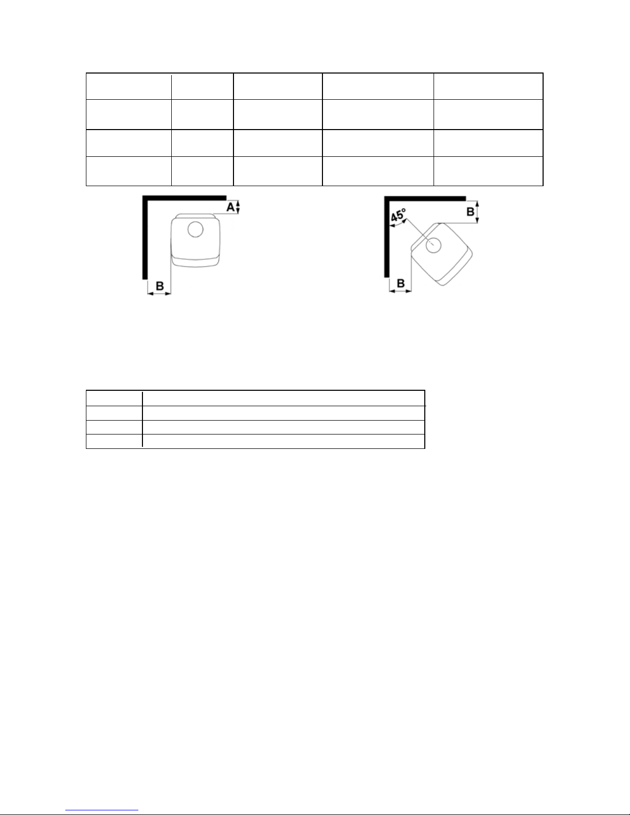
Clearance Distance to combustible materials:
Model Behind the To the sides
stove (A) of the stove (B) Above the stove To soft furnishings
Ø4 650 mm 550 mm 600 mm 700 mm
uninsulated flue
Ø6 700 mm 600 mm 600 mm 1100 mm
uninsulated flue
Ø8 850 mm 550 mm 600 mm 1100 mm
uninsulated flue
54
1.5 The chimney
Only if National or Local Regulations permit are you permitted to connect a stove into a chimney
that is shared by another appliance. YOU MUST be aware of any applicable Regulations in this
respect.
The wood-burning stove must never been connected to a chimney to which a gas-burning stove
or appliance is connected.
An efficient modern stove places heavy demands on the chimney, and you should have the
chimney regularly swept and inspected by your approved chimney sweep.
The cross-sectional area of the chimney (at its narrowest point) must comply with National and
Local Building Regulations. Generally, the area needed for an Ø-Collection wood-burning stove
installation should measure at least 175 cm2 (150 mm diameter).
An over-sized chimney is generally hard to keep warm and results in poor draft. In cases where
there is an oversized masonry chimney, it is recommended that the chimney be lined using an
appropriately chimney lining system with the correct internal diameter.
With respect to the chimney termination, all chimneys should terminate in accordance with
National and Local Building Regulations.
Note that National and Local Regulations also apply with regard to the placement of chimneys
and flues in connection with thatched roofs. See the section on Draft Conditions, 1.9.
The chimney or flue system must be equipped with access doors for inspection and cleaning
doors. The size of the cleaning door in the chimney must at least equal that of the cross-sectional area of the chimney.
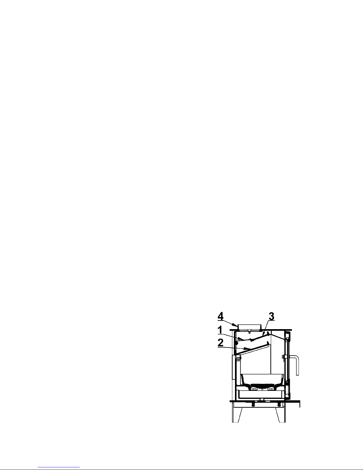
1.6 Pipe Connection
Your stove is supplied ready for a top flue connection (4). The rear flue outlet is fitted with a
cover plate and is situated on the back panel. Where a rear flue installation is required, unbolt
the flue collar. Unbolt the cover plate and install it onto the top of the stove. The flue collar can
then be bolted over the rear flue outlet using the bolts and clamps provided.
Make sure that the baffles (2 and 3), the firebricks,
and the riddling grate are positioned correctly.
Placement of draft reducer (only Ø4)
The Ø4 is supplied with a fitted draft reducer
(1) as shown in the diagram.
Where a rear flue exit (3) is required, the draft
reducer is not to be used.
 Loading...