


•
.
Instructions
Manual
MORS0
Mitring
machine
Model
F
61497
MASKINFABRIK
HARALDSVEJ
21 -
DK-8900 RANDERS - DANMARK
s
MASKINFABRIK
HARALDSVEJ
21
DK-8900
PANDERS
TLF.+45864351
55
FAX.
-i-
45 86 43
51
00
Instructions
manual
MORS0
Mitring
machine
Model
F
CONTENTS
0-1
I
I
Beware
of
the
extreme
sharp knives
Introduction page
A-l
Functional
Description
general description page
B-l
machine description
page
B-2
description
of the
lever system page
B-3
description
of
cutting page
B-4
Technical Data page
C-l
Dimensions
of
work
pieces page
C-2
Mounting
Instructions
general page
D-l
mounting
of
table extension
and
divided
beam page
D-l
Operating Instructions
operating
devices page
E-l
before
starting page
E-2
degree adjustment
of
fences page
E-3
adjustment
of
length
of
moulding
page
E-4
adjustment
of
rebate
supports page
E-5
adjustment
of
forward
movement page
E-5
adjustment
of
height stop page
E-6
working
procedure page
E-7
after
working
procedure page
E-7
Service References
lubrication
instructions page
F-l
cleaning
page
F-l
changing
of
knives
page
F-2
grinding
of
knives page
F-3
regulation
of
draw
bar
page
F-4
adjustment
of
forward
movement page
F-4
adjustment
of
springs page
F-5
adjustment
of
height
movement
page
F-6
changing
of
spare parts page
F-7
Locating
Faults / Methods
for
Repair page
G-l
Safety
safety
devices
regulations
page
H-l
page
H-l
MORS0 F -9503 0-1/gb1
MASKINFABRIK
HARALDSVEJ
21
DK-8900
PANDERS
TLF.
+ 45 86 43 51 55
FAX.
+ 45 86 43 51 00
Instructions manual
MORS0 Mitring machine
Model
F
CONTENTS
0-2
Beware
of
the
extreme
sharp knives
Index
of
Spare Parts
survey
machine
knife
block
unit
drive
mechanisme
rebate supports
Supplement
page
1-1
page
1-2
page
1-3
page
1-4
page
1-5
K
Accessories:
rebate
support
attachment, autom.
description
page
L-l-1
installation
instructions page
L-l-2
adjustment
of
rebate
supports page
L-l-3
index
of
spare parts page
L-2
MORS0 F -9503
0-2/gb1
4
MASKINFABRIK
HARALDSVEJ
21
DK-8900RANDERS
TLF.T45864351
55
FAX.
+ 45 86 43 51 00
Instructions
manual
MORS0 Mitring machine
Model
F
0©
Typ«EH
picture
A-1-1
I
INTRODUCTION
A-1
g
\
ipiWr
\
A-1
Beware
of
the
extreme
sharp
knives
We
recommend
to
read
this instruction manual
carefully
before
the
first
starting
of the
machine.
Defects
of the
machine provably arosen
due
to
mistakes
in
operation
will
not be
covered
by
the
warranty.
Use
of the
Instruction
Manual:
In
this instruction manual
all
information
needed
for
using
all
possibilities
of the
MORS0-mitring machine
is
found.
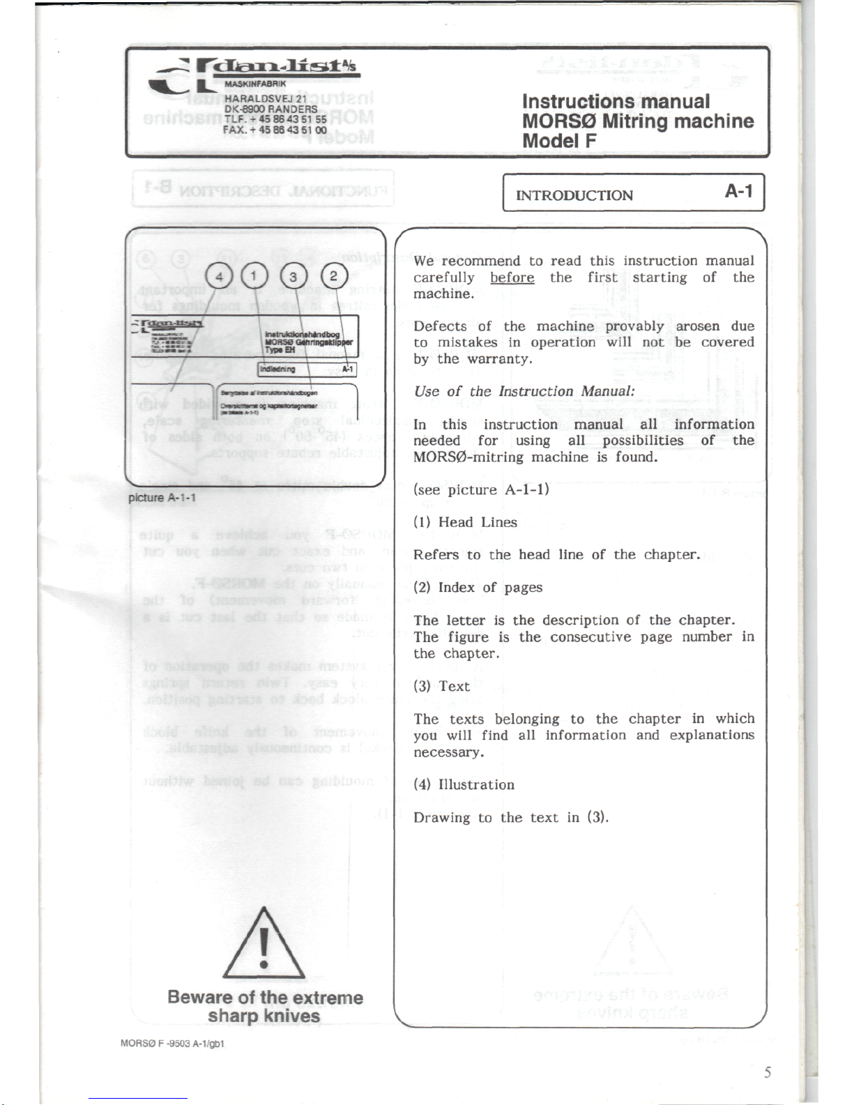
(see
picture
A-1-1)
(1)
Head Lines
Refers
to the
head line
of the
chapter.
(2)
Index
of
pages
The
letter
is the
description
of the
chapter.
The
figure
is the
consecutive
page number
in
the
chapter.
(3)
Text
The
texts
belonging
to the
chapter
in
which
you
will
find
all
information
and
explanations
necessary.
(4)
Illustration
Drawing
to the
text
in
(3).
MORS0 F -9503 A-1/gb1
I
g_
MASKINFABRI
HARALDSVEJ21
DK-8900
RANDERS
TLF.
+ 45 86 43 51 55
FAX.
+ 45 86 43 51 00
Instructions
manual
MORS0
Mitring machine
Model
F
picture
B-1-1
FUNCTIONAL
DESCRIPTION
B-1
Beware
of
the
extreme
sharp
knives
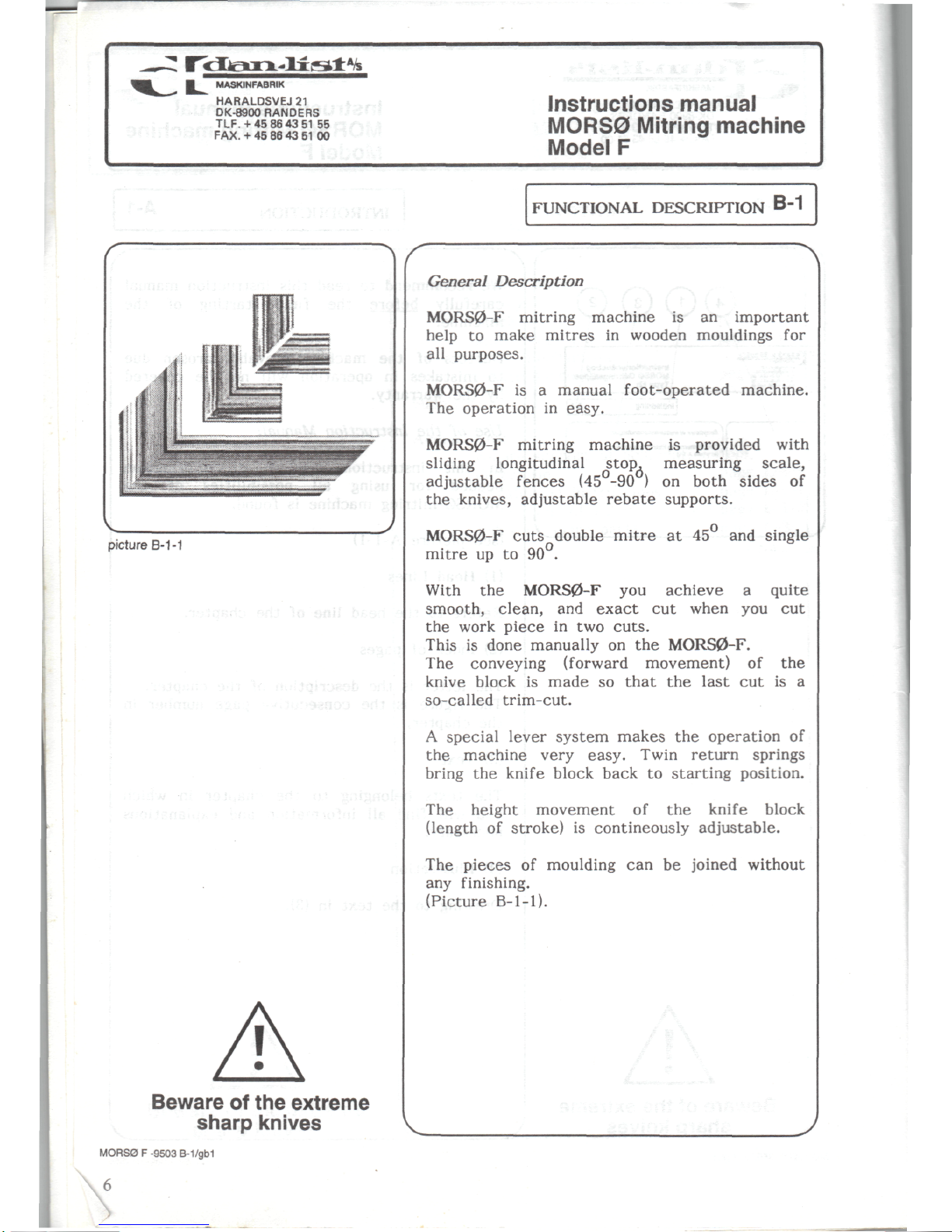
General
Description
MORS0-F
mitring machine
is an
important
help
to
make
mitres
in
wooden mouldings
for
all
purposes.
MORS0-F
is a
manual foot-operated machine.
The
operation
in
easy.
MORS0-F
mitring machine
is
provided with
sliding
longitudinal stop, measuring
scale,
adjustable
fences
(45°-90
) on
both
sides
of
the
knives, adjustable
rebate
supports.
MORS0-F
cuts
double
mitre
at 45 and
single
mitre
up to
90°.
With
the
MORS0-F
you
achieve a quite
smooth, clean,
and
exact
cut
when
you cut
the
work
piece
in two
cuts.
This
is
done manually
on the
MORS0-F.
The
conveying
(forward
movement)
of the
knive
block
is
made
so
that
the
last
cut is a
so-called
trim-cut.
A
special
lever
system
makes
the
operation
of
the
machine very
easy.
Twin return springs
bring
the
knife
block back
to
starting position.
The
height movement
of the
knife
block
(length
of
stroke)
is
contineously adjustable.
The
pieces
of
moulding
can be
joined without
any
finishing.
(Picture B-1-1).
MORS0 F -9503
B-1/gb1
MASKINFABRIK
HARALDSVEJ21
DK-8900
PANDERS
TLF.
+ 45 86 43 51 55
FAX.
+ 45 86 43 51 00
Instructions
manual
MORS0 Mitring machine
Model
F
FUNCTIONAL
DESCRIPTION
B-2
picture
B-2-1
I
Beware
of
the
extreme
sharp knives
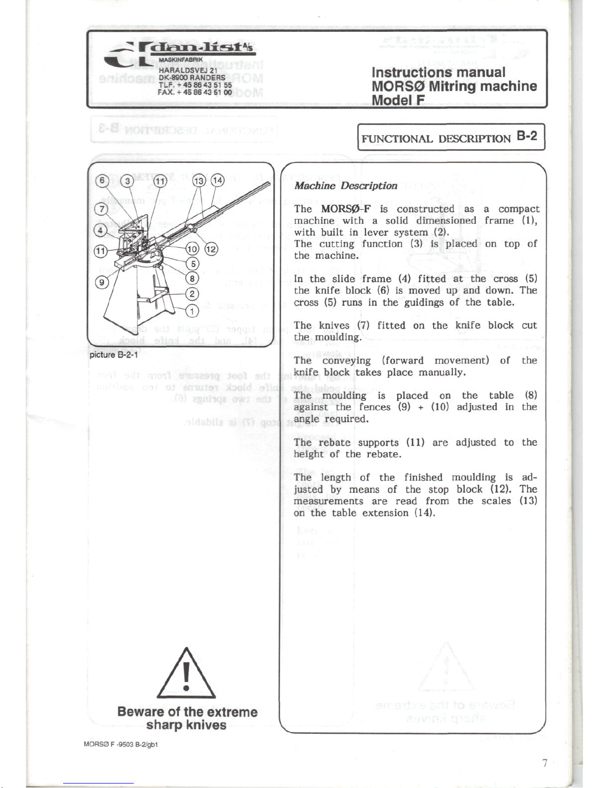
Machine
Description
The
MORS0-F
is
constructed
as a
compact
machine with a solid dimensioned frame (1),
with
built
in
lever
system
(2).
The
cutting function
(3) is
placed
on top of
the
machine.
In
the
slide frame
(4)
fitted
at the
cross
(5)
the
knife
block
(6) is
moved
up and
down.
The
cross
(5)
runs
in the
guidings
of the
table.
The
knives
(7)
fitted
on the
knife
block
cut
the
moulding.
The
conveying
(forward
movement)
of the
knife
block
takes
place
manually.
The
moulding
is
placed
on the
table
(8)
against
the
fences
(9) +
(10) adjusted
in the
angle
required.
The
rebate
supports
(11)
are
adjusted
to the
height
of the
rebate.
The
length
of the
finished moulding
is ad-
justed
by
means
of the
stop block (12).
The
measurements
are
read
from
the
scales
(13)
on
the
table extension (14).
MORS0 F -9503
B-2/gb1
MASKINFABRIK
HARALDSVEJ
21
DK-8900RANDERS
TLF.+
45864351
55
FAX.
+ 45 86 43 51 00
Instructions manual
MORS0 Mitring machine
Model
F
FUNCTIONAL
DESCRIPTION
B-3
picture
B-3-1
•
•
'
'
Beware
of
the
extreme
sharp knives
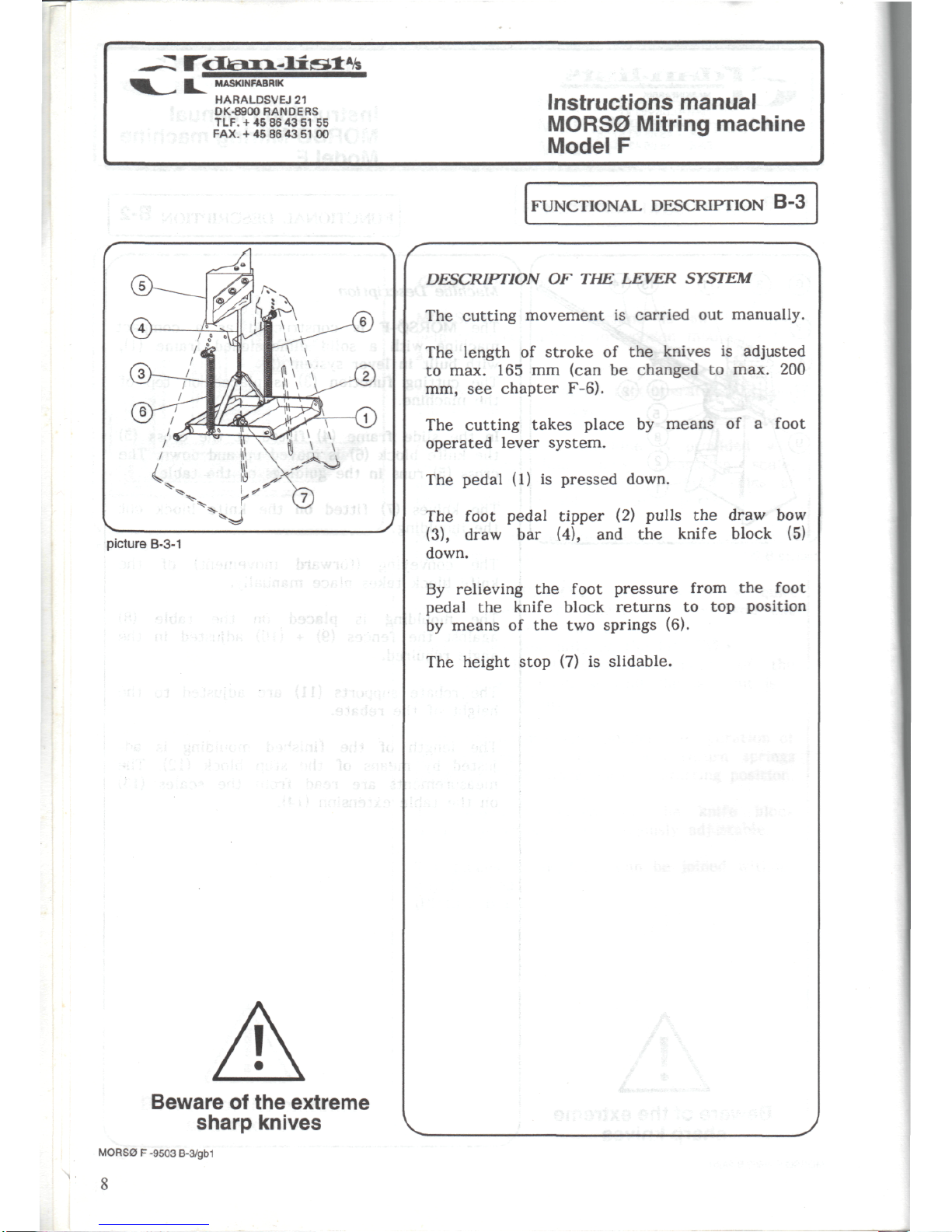
DESCRIPTION
OF THE
LEVER SYSTEM
The
cutting movement
is
carried
out
manually.
The
length
of
stroke
of the
knives
is
adjusted
to
max.
165 mm
(can
be
changed
to
max.
200
mm,
see
chapter F-6).
The
cutting takes place
by
means
of a
foot
operated lever
system.
The
pedal
(1) is
pressed
down.
The
foot pedal
tipper
(2)
pulls
the
draw
bow
(3),
draw
bar
(4),
and the
knife
block
(5)
down.
By
relieving
the
foot
pressure
from
the
foot
pedal
the
knife
block
returns
to top
position
by
means
of the two
springs (6).
The
height stop
(7) is
slidable.
.
MORS0 F -9503
B-3/gb1
8
MASKINFABRIK
HARALDSVEJ
21
DK-8900
BANDERS
TLF.-t-45
86 43 51 55
FAX.
+ 45 86 43 51
00
Instructions
manual
MORS0 Mitring machine
Model
F
FUNCTIONAL
DESCRIPTION
B-4
picture
B-4-1
I
Beware
of
the
extreme
sharp knives
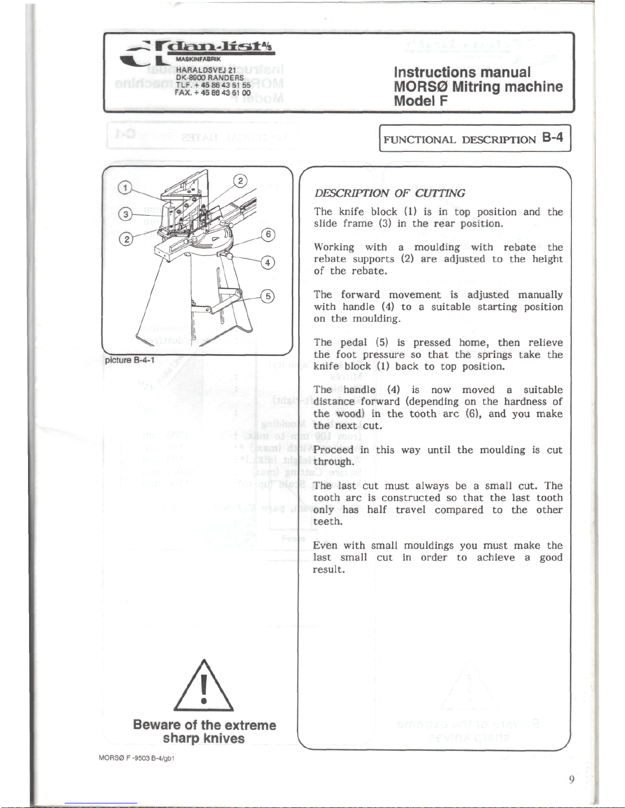
DESCRIPTION
OF
CUTTING
The
knife
block
(1) is in top
position
and the
slide
frame
(3) in the
rear position.
Working
with a moulding
with
rebate
the
rebate
supports
(2) are
adjusted
to the
height
of
the
rebate.
The
forward
movement
is
adjusted
manually
with
handle
(4) to a
suitable starting
position
on
the
moulding.
The
pedal
(5) is
pressed home, then relieve
the
foot
pressure
so
that
the
springs
take
the
knife
block
(1)
back
to top
position.
The
handle
(4) is now
moved a suitable
distance
forward
(depending
on the
hardness
of
the
wood)
in the
tooth
arc
(6),
and you
make
the
next
cut.
Proceed
in
this
way
until
the
moulding
is cut
through.
The
last
cut
must
always
be a
small
cut.
The
tooth
arc is
constructed
so
that
the
last tooth
only
has
half
travel compared
to the
other
teeth.
Even
with
small
mouldings
you
must make
the
last
small
cut in
order
to
achieve a good
result.
MORS0 F -9503 B-4/gb1
MASKINFABRIK
HARALDSVEJ21
DK-8900
RANDERS
TLF.+45864351
55
FAX.
-I-
45 86 43 51 00
Instructions manual
MORS0
Mitring machine
Model
F
picture
C-1-1
MORS
Beware
of
the
extreme
sharp knives
MORS0 F -9503 C-1/gb1
10
TECHNICAL
DATES
C-1
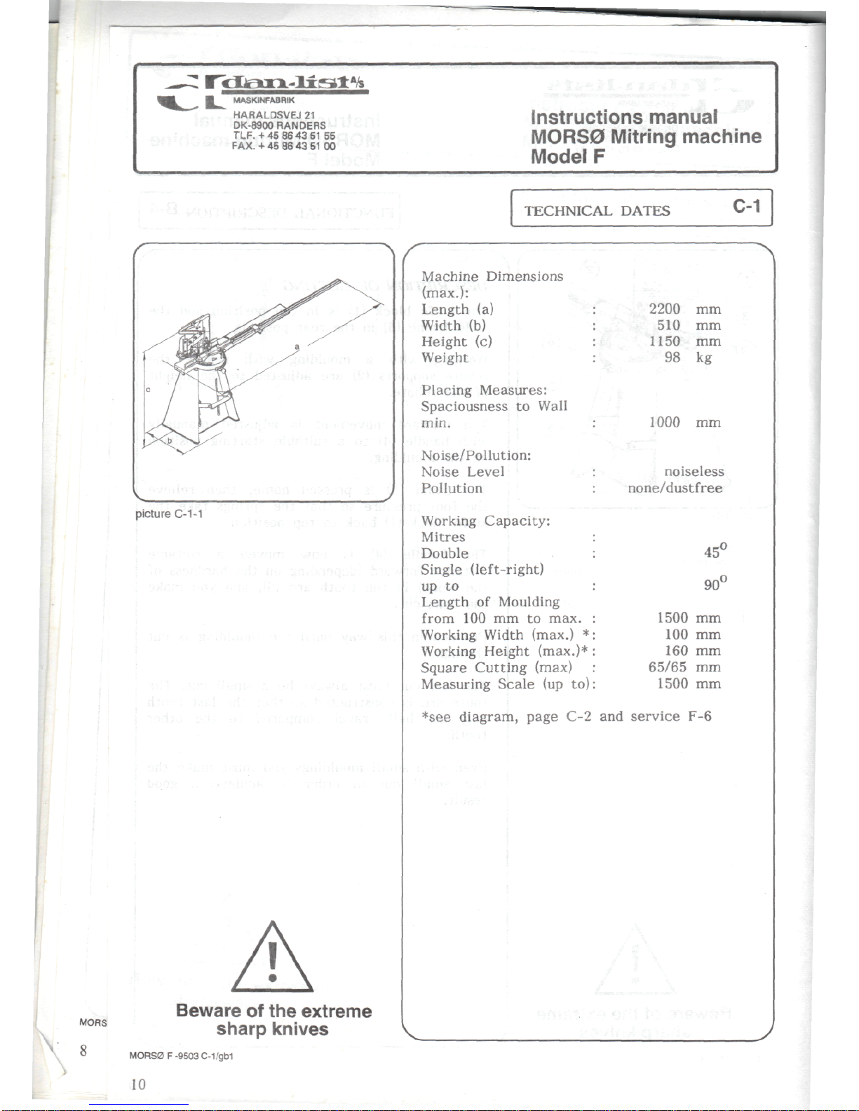
Machine Dimensions
(max.):
Length
(a)
Width
(b)
Height
(c)
Weight
Placing Measures:
Spaciousness
to
Wall
min.
Noise/Pollution:
Noise Level
Pollution
Working
Capacity:
Mitres
Double
Single (left-right)
up
to
Length
of
Moulding
from
100 mm to
max.
Working
Width
(max.)
*
Working
Height
(max.)*
Square
Cutting
(max)
Measuring
Scale
(up to)
2200
mm
510 mm
1150
mm
98 kg
1000
mm
noiseless
none/dustfree
45°
90°
1500
mm
100
mm
160
mm
65/65
mm
1500
mm
*see
diagram, page
C-2 and
service
F-6
r
MASKiNFABRIK
HARALDSVEJ21
DK-89CX)
BANDERS
TLF.
-f
45 86 43 51 55
FAX.
+
45 86 43 51 00
Instructions
manual
MORS0 Mitring machine
Model
F
TECHNICAL
DATES
C-2
90 70 50 30 10
100
picture
C-2-1
I
Beware
of
the
extreme
sharp knives
MORS0 F -9503
C-2/gb1
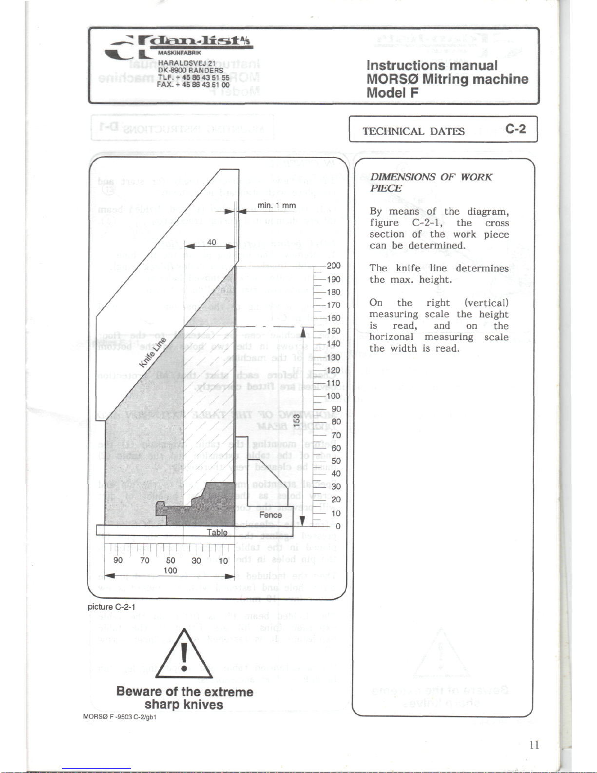
DIMENSIONS
OF
WORK
PIECE
By
means
of the
diagram,
figure
C-2-1,
the
cross
section
of the
work
piece
can
be
determined.
The
knife
line
determines
the
max. height.
On
the
right
(vertical)
measuring
scale
the
height
is
read,
and on the
horizonal
measuring
scale
the
width
is
read.
11
MASKINFABRIK
HARALDSVEJ
21
DK-8900
RANDERS
TLF.-1-45
86
43
51 55
FAX.
+
45 86 43 51 00
Instructions manual
MORS0
Mitring
machine
Model
F
picture
D-1-1
I
MOUNTING
INSTRUCTIONS
D-1
Beware
of the
extreme
sharp knives
IN
GENERAL
The
machine
is
delivered ready
for
start
and
complete with standard equipment.
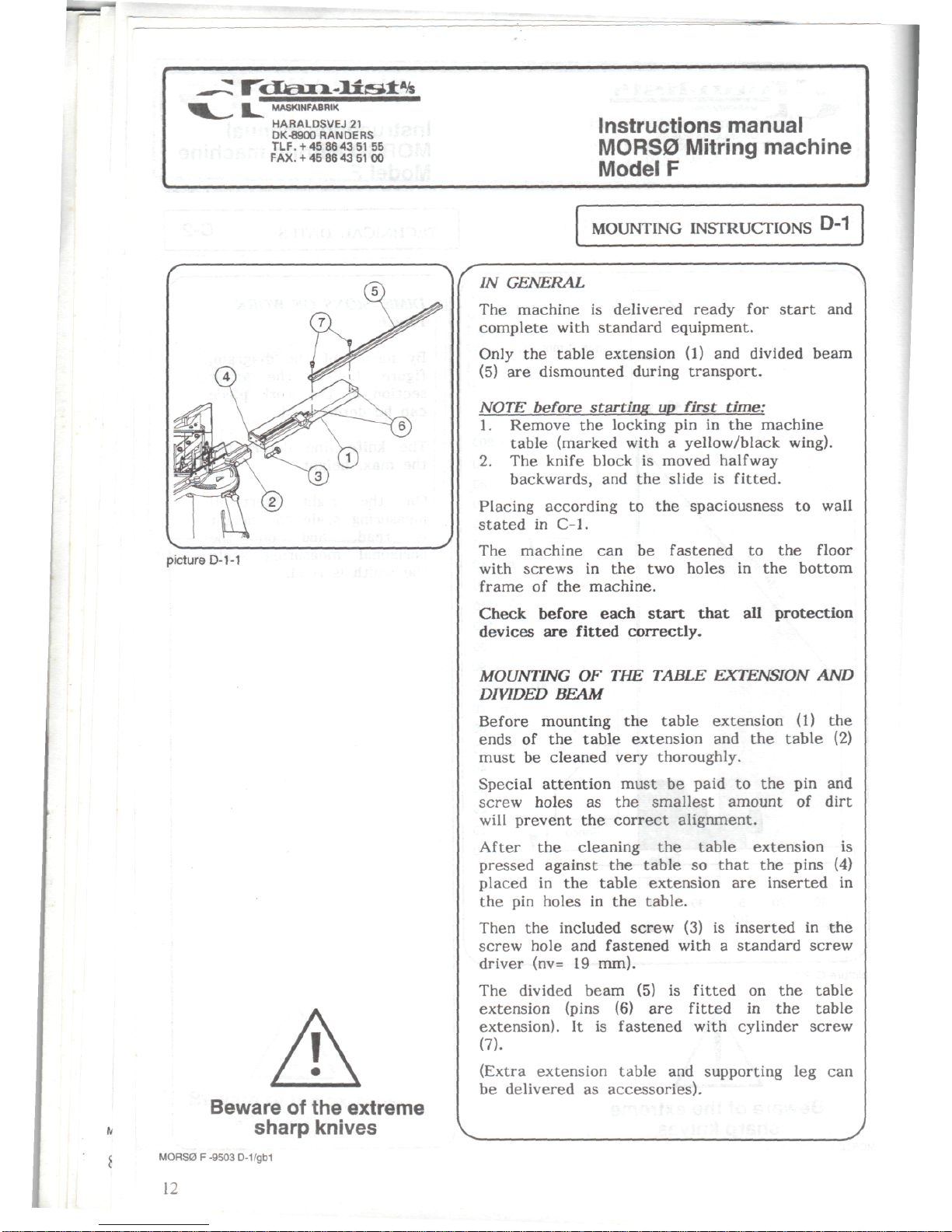
Only
the
table extension
(1) and
divided beam
(5)
are
dismounted
during
transport.
NOTE
before
starting
up
first time:
1.
Remove
the
locking
pin in the
machine
table (marked with a yellow/black
wing).
2. The
knife
block
is
moved
halfway
backwards,
and the
slide
is
fitted.
Placing
according
to the
spaciousness
to
wall
stated
in
C-l.
The
machine
can be
fastened
to the
floor
with
screws
in the two
holes
in the
bottom
frame
of the
machine.
Check
before each
start
that
all
protection
devices
are
fitted
correctly.
MOUNTING
OF THE
TABLE
EXTENSION
AND
DIVIDED
BEAM
Before
mounting
the
table
extension
(1) the
ends
of the
table
extension
and the
table
(2)
must
be
cleaned very thoroughly.
Special attention must
be
paid
to the pin and
screw holes
as the
smallest amount
of
dirt
will
prevent
the
correct alignment.
After
the
cleaning
the
table extension
is
pressed against
the
table
so
that
the
pins
(4)
placed
in the
table
extension
are
inserted
in
the pin
holes
in the
table.
Then
the
included screw
(3) is
inserted
in the
screw hole
and
fastened with a standard screw
driver
(nv=
19
mm).
The
divided
beam
(5) is
fitted
on the
table
extension
(pins
(6) are
fitted
in the
table
extension).
It is
fastened with cylinder screw
(7).
(Extra extension table
and
supporting
leg can
be
delivered
as
accessories).
MORS0 F -9503
D-1/gb1
12

MASKINFABRIK
HARALDSVEJ
21
DK-8900
BANDERS
TLF.+
45864351
55
FAX.
+ 45 86 43 51 00
Instructions
manual
MORS0
Mitring
machine
Model
F
OPERATING
INSTRUCTIONS
E-1
picture
E-1-1
f
Beware
of
the
extreme
sharp
knives
OPERATING DEVICES
1 = Handle - fastens
the
left fence
2 = Scale - degree
adjustment
of
left fence
3 =
Handle - fastens
the
right
fence
4 = Scale - degree
adjustment
of
right fence
5
= Nut -
height adjustment
of
left
rebate
support
6
= Nut -
height adjustment
of
right
rebate
support
7 =
Hand
Lever - forward
movement
8 =
Tooth
Arc -
forward
movement
9 - Star
Wheel - adjustment
of
stop beam
10 = Scale - length adjustment
11 = Foot
pedal - cutting
movement
of the
knife
block
12 = Screw - height stop
for
knife
block
13 = Star
Wheel - fastens safety guard
MORS0 F -9503 E-1/gb1
13
MASKINFABRIK
HARALDSVEJ21
DK-8900
RANDERS
TLF.+
45864351
55
FAX.
+ 45 86 43 51 00
picture
E-2-1
I
Instructions
manual
MORS0 Mitring machine
Model
F
OPERATING
INSTRUCTIONS
E-2
Beware
of
the
extreme
sharp knives
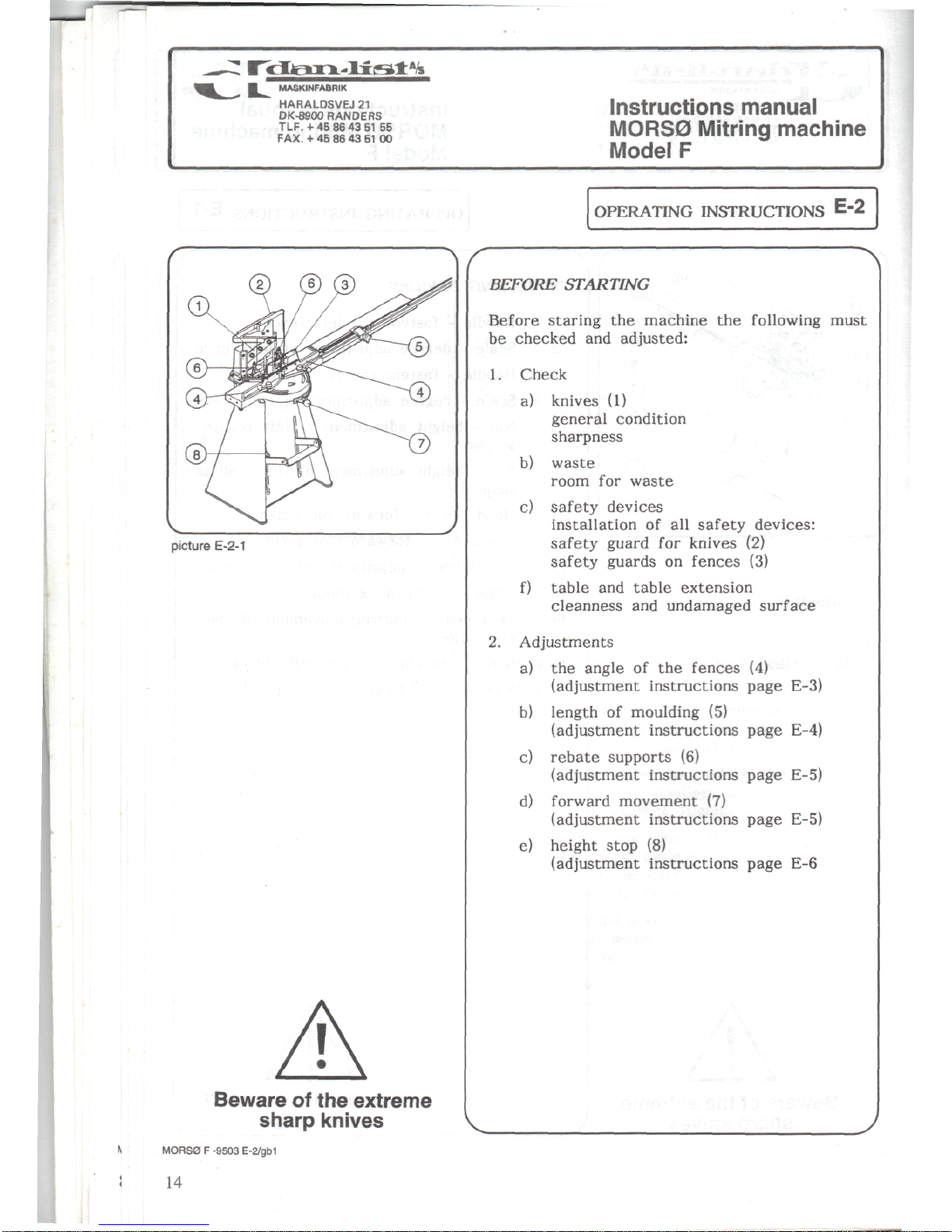
BEFORE
STARTING
Before
staring
the
machine
the
following
must
be
checked
and
adjusted:
1.
Check
a)
knives
(1)
general condition
sharpness
b)
waste
room
for
waste
c)
safety
devices
installation
of all
safety
devices:
safety guard
for
knives
(2)
safety
guards
on
fences
(3)
f)
table
and
table extension
cleanness
and
undamaged
surface
2.
Adjustments
a)
the
angle
of the
fences
(4)
(adjustment
instructions page E-3)
b)
length
of
moulding
(5)
(adjustment
instructions page E-4)
c)
rebate
supports
(6)
(adjustment instructions page E-5)
d)
forward movement
(7)
(adjustment
instructions page E-5)
e)
height stop
(8)
(adjustment
instructions page
E-6
MORS0 F -9503
E-2/gb1
14
 Loading...