

1
MORSØ JERNSTØBERI A/S . DK-7900 NYKØBING MORS
E-Mail: stoves@morsoe.com · Website: www.morsoe.com
A French version of the manual can be downloaded at www.morsona.com
Installation and Operating Instructions
1410 Squirrel
For use in North America
Read this entire manual before you install and use your new room heater. If this room heater is
not properly installed, a house fire may result. To reduce the risk of fire, follow the installation
instructions. Failure to follow instructions may result in property damage, bodily injury, or
even death.
Contact local building officials about restrictions and installation/inspection-requirements
in your area.
Save these instructions
2
We congratulate you on your choice of a Morsø stove. Morsø has been
producing some of the world’s best stoves since 1853. If you follow this
installation- and operating instruction carefully, we can assure you
many years of warmth and pleasure.
Optional Accessories
A wide range of accessories (such as handling gloves, fireside tools, glass cleaner and heatproof
paint) are available for use with your Morsø stove. They help with day-to-day running and
maintenance. Contact your Morsø dealer for more information.
The Morsø 1410 squirrel meets the U.S. Environmental Protection Agency’s emission limits for
wood heaters sold on or after July 1, 1990
The Morsø 1410 squirrel are listed by OMNI-Test Laboratories, Inc. The test standards are ANSI/
UL-1482 for the United States and ULC S627 for Canada.
The stove is listed for burning wood only. Do not burn other fuels.
Under specific test conditions this heater has been shown to deliver heat at rates ranging from
9,600 to 22,000 Btu´s.
Cast iron
Cast iron is a live material. There are no two ovens that are identical. This is partly due to the
tolerances of the casting process, partly because the ovens are a work of craftsmanship.
Minor unevennesses may also occur in the cast iron surface.
3
CONTENTS:
1.0 Installation of your Morsø stove 3
1.1 Unpacking the stove 4
1.2 Checking loose parts in the stove 4
1.3 The chimney / flue system 5
1.4 Flue Connection 6
1.5 Connection to existing chimney 6
1.6 Positioning the stove 8
2.0 Operation 11
2.1 Before you start firing 11
2.2 Lighting and loading intervals 12
3.0 Maintenance 14
3.1 Exterior maintenance 14
3.2 Internal maintenance 14
3.3 Cleaning the Stove and the Flue 16
3.4 Leaving the stove for extended periods 17
3.5 Parts diagram 18
3.6 Parts list 19
1.0 Installation of your Morsø stove
Installation of woodburning stoves must be safe and legal.
If your Morsø stove is not installed correctly, it may cause a house fire. To reduce
the risk of fire, the installation instructions must be followed carefully. Contact the
local building officials about restrictions and installation inspection in your area.
Before you start installing your stove, make sure that:
- The stove and chimney connection are placed far enough from combustible materials to meet
all clearance requirements.
- The floor protection must be adequate and must be made correctly according to ´the re-
quirements.
All neccessary approvals are needed from the local building officials.
The data plate, which is located on the back of the stove, provides information regarding safety
testing information, name of certified testing laboratory, and installation requirements.
4
Installation requirements vary in different districts, and the local building officials have the final
authorization to approve your installation. You should discuss the installation with them before
beginning. Please ask your dealer for further information.
Do not connect to any air distribution duct or system.
Important: If the installation instructions are not followed carefully, it may cause dangerous situations like chimney - and house fires. Follow the instructions carefully and do not
deviate from them as it may cause injuries to people or property.
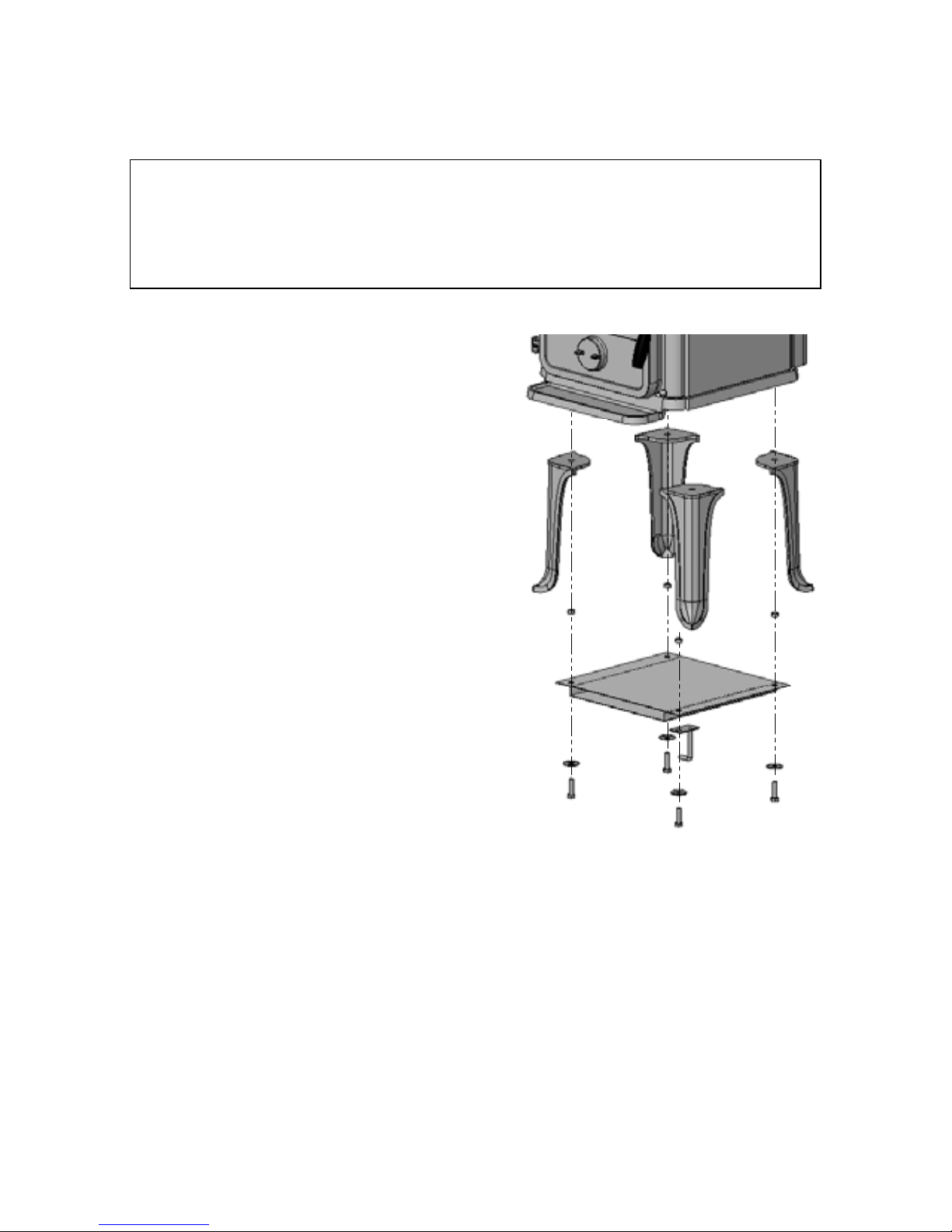
1.1 Unpacking the stove
After removing the outer packaging, flatten it and lay
onto the floor close to the stove; this can then act as
protective work surface during the assembly process.
Next, remove the legs from inside the stove. Carefully
lift the stove from the wooden pallet and gently lay the
stove onto its back and unscrew the heat shield from
the underside of the stove. Now screw the legs and
the Heat shield into position on the underside of the
base. Following the removal of the wooden packaging
the heat shield must be fitted to the underside of the
stove at the same time as the legs utilising the same
fixing bolts. Please see drawing.
The stove should now be lifted and moved into the
upright position, avoiding excess load on the back
legs.
We recommend that two people perform the assembly
and installation procedure. The Morsø 1410 weighs
75 kg.
1.2 Checking loose parts in the stove
After unpacking, check that the center grate (in the
centre of the fire bed) and the fire bricks are firmly
in position and have not shifted in transit. Check also
that the air control works freely.
Standard Accessories
Poker, ceramic flue connection gasket and riddling tool are standard accessories, and can usually
be found in the ashpan or firebox area.
5
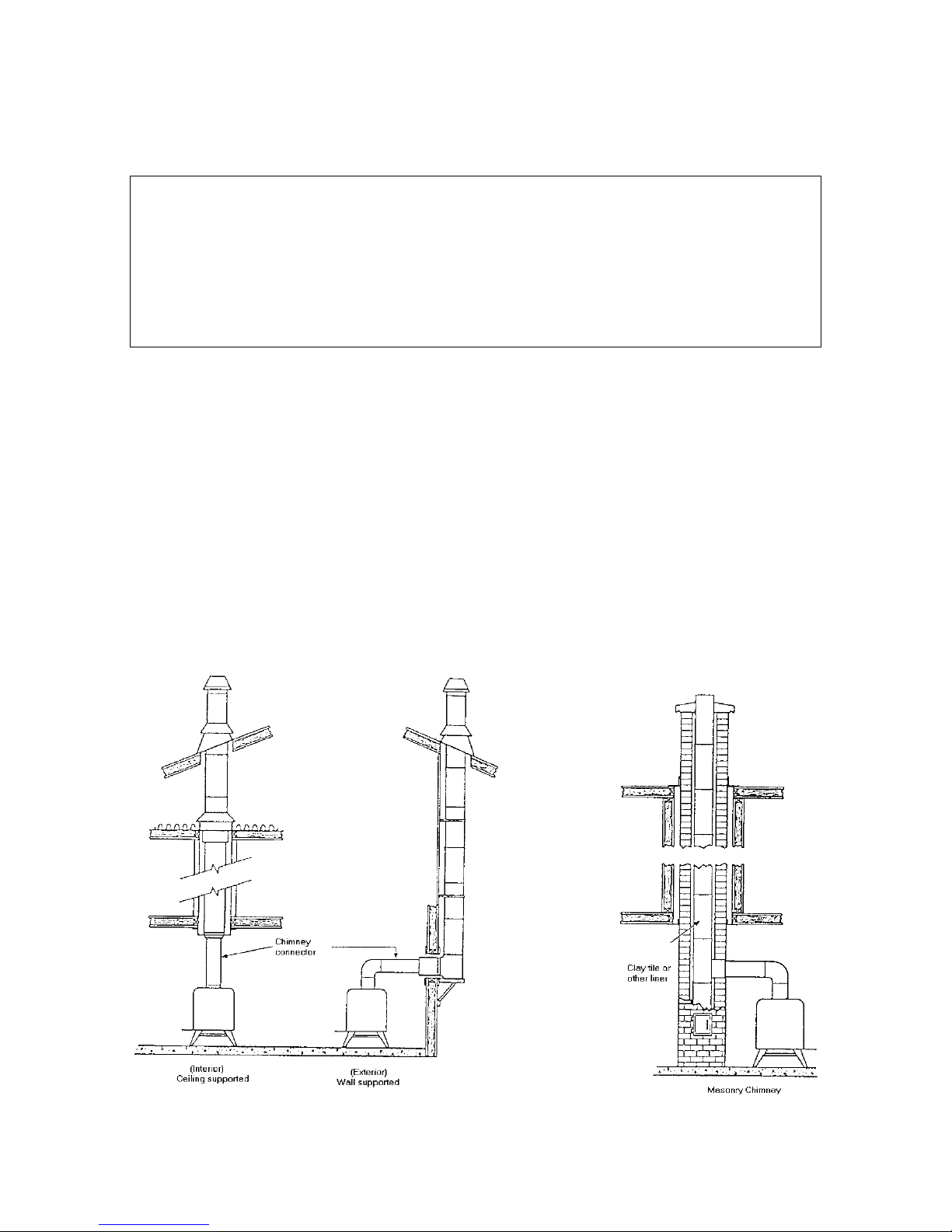
1.3 The chimney / flue system
Note that the flue system must be independently secured and must not rely on the stove for
support.
The stove must not be connected to a chimney flue serving any other appliance.
(Several flues may run up a single chimney stack; use one flueway per appliance).
Use a residential type masonry or listed type HT factory-built chimney.
High Temperature (H.T.) Chimney Standard UL-103-1985 (2100º F.) for the USA, and High
Temperature (650ºC) Standard ULC S-629 for Canada.
The internal dimensions of the chimney connector and chimney must not be less than 6 inches
diameter (or equivalent cross section), and should not be significantly larger than this. Too
large a section will tend to allow the flue gases to cool excessively, causing sluggishness or
unpredictability in the stove’s performance.
We recommend the length of the chimney system should be at least 16 feet (not required) above
the stove in normal domestic situations, measured from the flue collar to the top of the chimney.
Local conditions like for example - roof constructions, large trees nearby and high altitude, may
influence the chimney draft and height. Therefore, contact the local professional chimney sweep
or your Morsø dealer.
Typical Factory-Built or Masonry Chimney Installations
6
Double-wall connectors must be tested and listed for use with solid-fuel burning appliances.
Single-wall connectors should be made of 24 gauge or heavier gauge steel. Do not use galvanized
connector; it cannot withstand the high-temperatures that smoke and exhaust gases can reach,
and may release toxic fumes under high heat. The connector must be 6 inches (150mm) in diameter.
If possible, do not pass the chimney connector through a combustible wall or ceiling.
If passage through a combustible wall is unavoidable, refer to the sections on Wall PassThroughs. Do not pass the connector through an attic, a closet or similar concealed space
when installing the chimney connectors.
It is important to keep the flue gases moving smoothly in the right direction. Do not vent into a
large void at this location; rather form one continuous section all the way up. Use mild bends
(e.g. 45º vs. 90º) rather than sharp angles where a change of direction is required. All parts of
the venting must be accessible for cleaning purposes.
In horizontal runs of chimney, maintain a distance of 18 inches from the ceiling. Keep it as
short and direct as possible, with no more than two 90 degree turns. Slope horizontal runs of
connector upward 1/4 inch per foot (20 mm per metre) going from the stove toward the chimney.
The recommended maximum length of a horizontal run is 3 feet (1 metre), and the total length
should be no longer than 8 feet (2.5 metres).
Information on assembling and installing connectors is provided by the manufacturer’s instructions
exactly as you assemble the connector and attach it to the stove and chimney.
Be sure the installed stove and chimney connector are correct distances from near by
combustible materials. See the clearance paragraph page 8.
1.4 Flue Connection
The stove is supplied from the factory with a flue collar fitted to the top plate and a round blanking
plate blocking off the rear flue exit (behind the rear shield plate).
The flue collar is from the factory prepared for fitting the enlosed 6 inche adapter.
Use a 24 MSG black or blue chimney connector or listed double wall chimney connector. Refer
to local codes and the chimney manufacturer’s instructions for precautions required for passing
a chimney through a combustible wall or ceiling. Remember to secure the chimney connector
with a minimum of three screws to the product and to each adjoining section.
The collar can be fitted to the rear outlet. Simply knock out the round panel on the rear heat
shield plate to reveal the cast iron plate. Untwist the blanking plate and the flue collar and swap
their positions. Re-secure by pushing down and tighten the enclosed screws.
Position the stove and connect to the flue system.
Wear gloves and protective eyewear when drilling, cutting or joining sections of chimney
connector
1.5 Connection to the existing chimney
A Chimney connector is the double-wall or single-wall pipe that connects the stove to the chimney.
The chimney itself is the masonry or prefabricated structure that encloses the flue. Chimney
connectors are used only to connect the stove to the chimney.
 Loading...