

Page 1

OPERATOR’S MANUAL
Air Drill
S66250-01
Page 2

Page 3

Table of Contents
Section 1:
Safety ............................................................................................................................1-1
Signal Words ................................................................................................................. 1- 2
General Operation ......................................................................................................... 1- 3
Tractor Operation ...........................................................................................................1- 3
Chemicals...................................................................................................................... 1- 4
Transporting ...................................................................................................................1- 5
Hydraulics ...................................................................................................................... 1- 5
Maintenance .................................................................................................................. 1- 6
Storage .......................................................................................................................... 1- 6
Safety Signs ..................................................................................................................1- 7
Lighting and Marking ................................................................................................... 1- 12
Section 2:
Specifications ..............................................................................................................2-1
Specifications and Options.........................................................................................2-2
Transport Dimensions ....................................................................................................2-3
Section 3:
Checklist ......................................................................................................................3-1
Manuals .........................................................................................................................3-2
Parts Manual .............................................................................................................3-2
Assembly Manual .......................................................................................................3-2
Checklist ........................................................................................................................3-3
Section 4:
Introduction .................................................................................................................4-1
Introduction ....................................................................................................................4-2
Active Hydraulic System ................................................................................................4-3
Section 5:
Operation .....................................................................................................................5-1
Application .....................................................................................................................5-2
Tractor ............................................................................................................................5-2
Hitching ........................................................................................................................5-3
Hitching to Tractor ......................................................................................................5-3
Unhitching from Tractor ..............................................................................................5-4
JEM CC Pilot Dispay Wiring .......................................................................................5-5
X35 Apollo - Lift and Pressure Control Wiring.............................................................5-6
Transport ........................................................................................................................5-8
Transport to Field Position ..........................................................................................5-9
Field to Transport Position .........................................................................................5-10
Opener Hydraulic System ........................................................................................... 5-11
Operation ................................................................................................................. 5-11
Lifting/Lowering ..................................................................................................... 5-11
Pressure Setting ....................................................................................................5-12
Limp home mode (manual hydraulic operation) ....................................................5-12
Controller Options .......................................................................................................5-13
JEM CC Pilot Dispay ................................................................................................5-13
Topcon - X35 Apollo .................................................................................................5-14
Lift Control Setup ..................................................................................................5-15
Hydraulic Pressure Control Setup .........................................................................5-18
Pack Control Setup ...............................................................................................5-23
Pack Control Calibration ........................................................................................5-28
Depth Adjustment ........................................................................................................5-33
Work Switch .................................................................................................................5-35
General Guidelines ......................................................................................................5-36
January 2019 I
Page 4

Table of Contents
Quick Tips ....................................................................................................................5-37
Shank Trip Force .......................................................................................................5-37
Packing Force ...........................................................................................................5-37
Hydraulic System .....................................................................................................5-37
Lifting and Lowering the Openers ............................................................................5-37
Setting the Seed Depth ............................................................................................5-38
Seeding Conditions ..................................................................................................5-38
Straw Management ..................................................................................................5-38
Air Drill Frame ..........................................................................................................5-39
Wing Lift Hydraulics .....................................................................................................5-40
Opener Hydraulics ......................................................................................................5-42
Section 6:
Maintenance .................................................................................................................6-1
General ..........................................................................................................................6-2
Safety ............................................................................................................................6-2
Tighten Bolts .................................................................................................................6-3
Tires ..............................................................................................................................6-3
Lubrication .....................................................................................................................6-4
Opener Maintenance .....................................................................................................6-5
Bushing Replacement ................................................................................................6-5
Cylinder Replacement ................................................................................................6-5
Opener Body Assembly..............................................................................................6-6
Opener Assembly .......................................................................................................6-8
Shank Replacement .................................................................................................6-15
Bleeding Hydraulic System.......................................................................................6-16
Hydraulic System Trouble Shooting ..........................................................................6-17
Hydraulics ....................................................................................................................6-18
Wheel Bearings ...........................................................................................................6-19
Implement Hub .........................................................................................................6-19
Contour Opener Hub ................................................................................................6-20
Section 7:
Storage ......................................................................................................................... 7- 1
Preparing for Storage .................................................................................................... 7- 2
Wing Lift Cylinder Shaft Protection ............................................................................... 7- 3
Removing From Storage ................................................................................................ 7- 3
Section 8:
Troubleshooting...........................................................................................................8-1
Machine not operating straight. .....................................................................................8-2
Lack of penetration. .......................................................................................................8-2
Openers wearing unevenly ............................................................................................8-2
Wing lifting too slowly. ....................................................................................................8-2
Wings not lowering. .......................................................................................................8-2
One wing will lift, other will not. .....................................................................................8-2
Oil accumulation. ...........................................................................................................8-2
Openers drop quickly after transport lock valve is closed. .............................................8-2
Openers won’t lift or lower. .............................................................................................8-3
Openers won’t lift. ..........................................................................................................8-3
Opener pressure won’t change. ....................................................................................8-3
Openers can not be fully pressurized. ...........................................................................8-3
Openers not fully lifting to transport position. .................................................................8-4
Excessive seed depth and soil throw. ............................................................................8-4
Shanks hang back and trip out during normal operation. ..............................................8-4
Seed rows covered in loose soil after seeding. ..............................................................8-4
Packer wheels bounce and chatter excessively in field. ................................................8-4
I January 2019
Page 5

Section 1: Safety
Safety
Section 1:
Safety 1-1
Section Contents
Signal Words ..................................................................................................................... 1- 2
General Operation ............................................................................................................ 1-3
Tractor Operation ..............................................................................................................1-3
Chemicals .........................................................................................................................1- 4
Transporting ...................................................................................................................... 1- 5
Hydraulics .........................................................................................................................1- 5
Maintenance ..................................................................................................................... 1-6
Storage ............................................................................................................................. 1- 6
Safety Signs .....................................................................................................................1-7
Lighting and Marking ...................................................................................................... 1-12
January 2019 1-1
Page 6
Safety
Watch for this symbol. It identifies potential hazards
SAFETY-ALERT
SYMBOL
Familiarize yourself with the location of all decals. Read them
carefully to understand the safe operation of your machine.
Signal Words
The words DANGER, WARNING or CAUTION are used
with the safety alert symbol. Learn to recognize the
safety alerts, and follow the recommended precautions
and safe practices.
to health or personal safety. It means:
ATTENTION - BE ALERT.
Your Safety is involved.
Three words are used in conjunction with the safety-alert symbol:
DANGER
WARNING
CAUTION
Replace any DANGER, WARNING, CAUTION or
instructional decal that is not readable or is missing. The
location and part number of these decals is identied
later in this section of the manual.
The words Important and Note are not related
to personal safety but are used to give additional
information and tips for operating or servicing this
equipment.
IMPORTANT: Identifies special instructions or
procedures which, if not strictly
observed could result in damage to, or
destruction of the machine, process or
its surroundings.
Indicates an imminently hazardous situation that, if not
avoided, will result in DEATH OR SERIOUS INJURY.
Indicates a potentially hazardous situation that, if not
avoided, could result in DEATH OR SERIOUS INJURY.
Indicates a potentially hazardous situation that, if not
avoided, may result in MINOR OR MODERATE INJURY.
NOTE: Indicates points of particular interest for more
efcient and convenient repair or operation.
1-2 January 2019
Page 7
General Operation
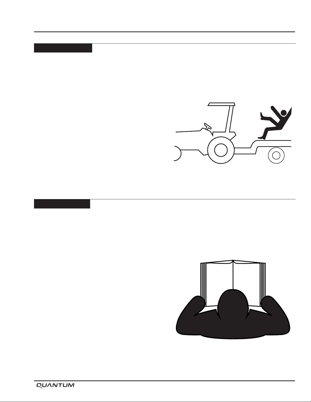
• DO NOT RIDE!! Do not allow riders on the implement
when in motion.
• Do not allow extra riders in the tractor unless an
instructor seat and seat belt are available.
• Check behind when backing up.
• Reduce speed when working in hilly terrain.
• Never allow anyone within the immediate area when
operating machinery.
• Stand clear when raising or lowering wings.
• Keep all shields in place, replace them if removed
for service work.
Safety
Tractor Operation
• Be aware of the correct tractor operating procedures,
when working with implements.
• Review tractor operator’s manual.
• Secure hitch pin with a retainer and lock drawbar in
centre position.
January 2019 1-3
Page 8
Safety
Chemicals
•
Use extreme care
making adjustments.
• Always read granular chemical or treated seed
manufacturer’s warning labels carefully and
remember them.
• Wear close tting clothing and appropriate personal
protective equipment for the job as specied by the
chemical and/or seed manufacturer.
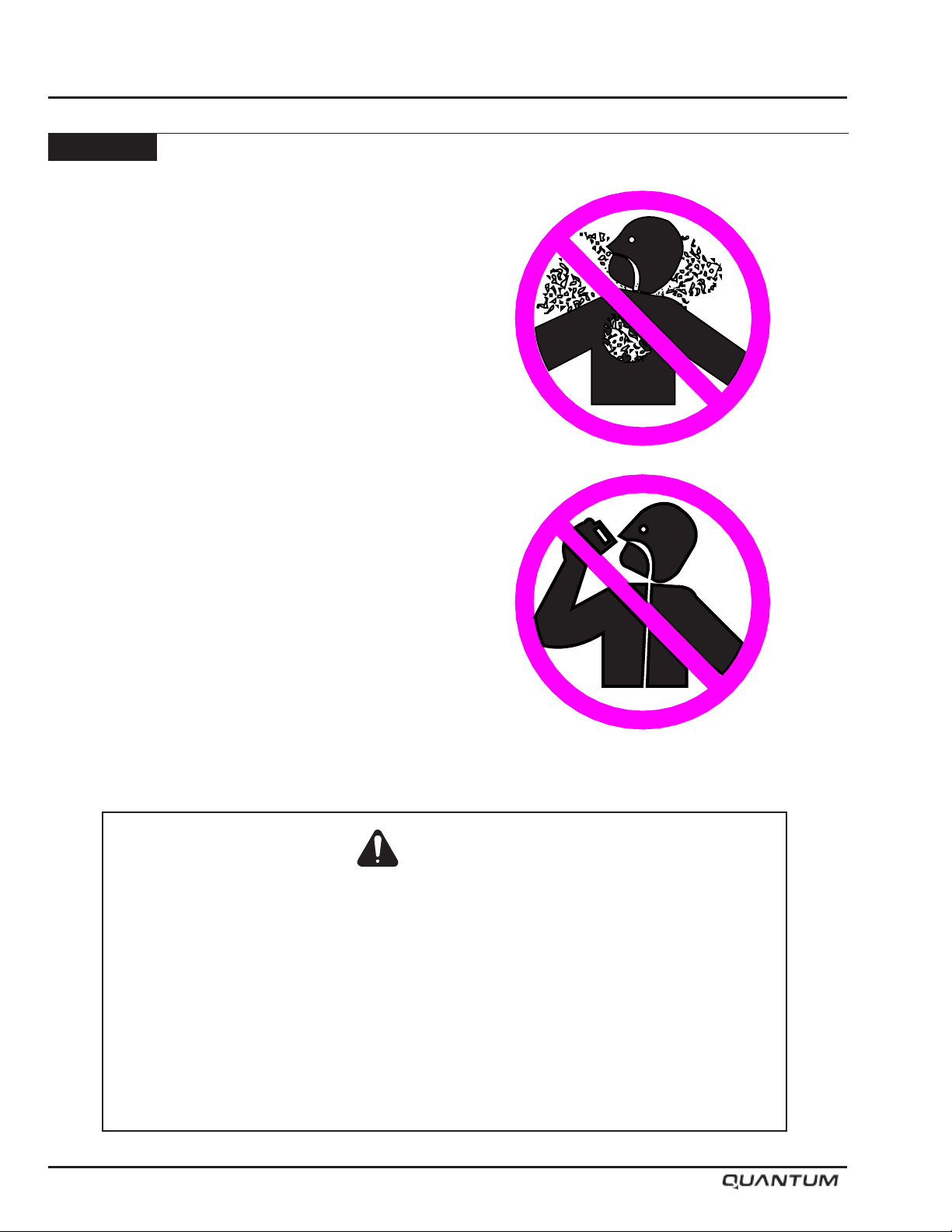
•
Always wear
apparatus and gloves when handling with granular
chemical or treated seed.
• Do not feed any treated seed to livestock. Treated
seed is poisonous and may cause harm to persons
or livestock.
• Wash exposed skin immediately - do not leave
chemicals on your skin.
• Properly store chemicals in original containers with
labels intact per the manufacturer’s instructions.
• Always follow the manufacturer’s operating
instructions and warning labels when operating an
ammonia tank with the equipment.
• Do Not enter Air Cart tank unless
another person is present and the
tractor engine has been shut off.
when cleaning, filling or
safety goggles, breathing
Danger
Failure to comply may result in death or serious injury.
Read Operator’s Manual and decals on Ammonia tank before operating Air Cart.
Become familiar with all warnings, instructions, and controls.
Always wear gloves and goggles when transferring or handling ammonia.
Always stay clear of hose and valve openings.
Always be sure pressure is relieved before disconnecting hoses or parts.
Always secure connecting parts and safety chains before towing ammonia trailer.
Always have ample water available in case of exposure to ammonia liquid or gases.
1-4 January 2019
Page 9

Transporting
• Be aware of the height, length and width of
implement. Make turns carefully and be aware of
obstacles and overhead electrical lines.
• Always travel at a safe speed. Do Not Exceed 20
mph (32 kph).
• Use an agricultural tractor that is large enough with
sufcient braking capacity so that the weight of the
loaded equipment towed does not exceed 1.5 times
the weight of the tractor.
• Use ashing amber warning lights, turn signals and
SMV emblems when on public roads.
• Do not transport in poor visibility.
• The slow moving vehicle (SMV) emblem and
reectors must be secured and be visible on the
machine for transport.
• Avoid soft surfaces, the additional wing weight on
the centre wheels could cause the machine to sink.
• Ensure safety chain is attached correctly to the
towing vehicle and the hitch of the implement.
• Check that wings are rmly seated on transport wing
stops, and wing lift valve and opener valve are in
locked postion.
• Be familiar with and adhere to local laws.
Hydraulics
• Do not search for high pressure hydraulic leaks
without hand and face protection. A tiny, almost
invisible leak can penetrate skin, thereby requiring
immediate medical attention.
• Use cardboard or wood to detect leaks - never your
hands.
• Double check that all is clear before operating
hydraulics.
• Never remove hydraulic hoses or ends with machine
elevated. Relieve hydraulic pressure before
disconnecting hydraulic hoses or ends.
• Maintain proper hydraulic uid levels.
• Keep all connectors clean for positive connections.
• Ensure all ttings and hoses are in good condition.
• Do not stand under wings.
Safety
January 2019 1-5
Page 10
Safety
Maintenance
• Shut tractor engine off before making any
adjustments or lubricating the machine.
• Block machine securely to prevent any movement
during servicing.
• Wear close tting clothing and appropriate personal
protective equipment for the job.
• Always wear safety goggles, breathing apparatus
and gloves when working on seeder lled with granular
chemical or treated seed per the manufacture’s
instructions.
• Do not modify the machine.
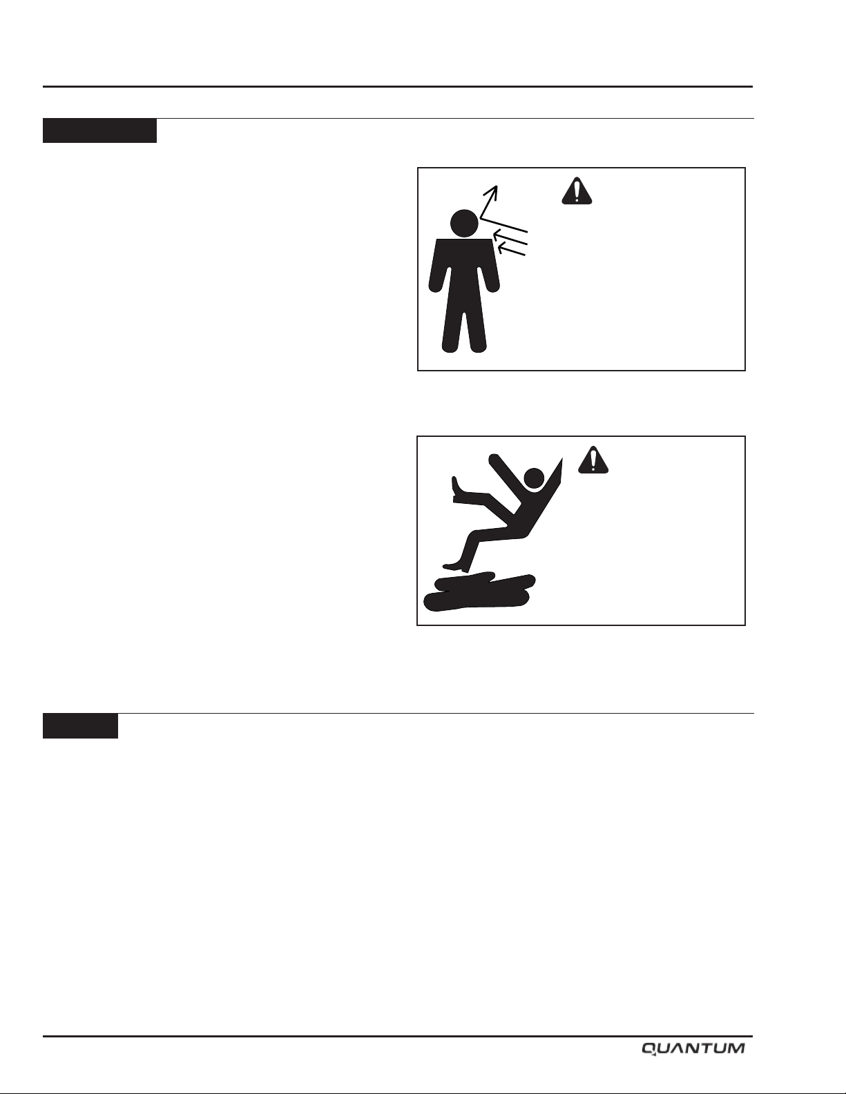
Caution
Care should be taken when
working near the air cart
while the fan is running.
Product blowing out of
the system could cause
personal injury.
Caution
Storage
• Store implement away from areas of main activity.
• Level implement and block up securely to relieve
pressure on jack.
• Do not allow children to play on or around stored
implement.
Keep service area clean
and dry. Wet or oily
floors are slippery.
1-6 January 2019
Page 11
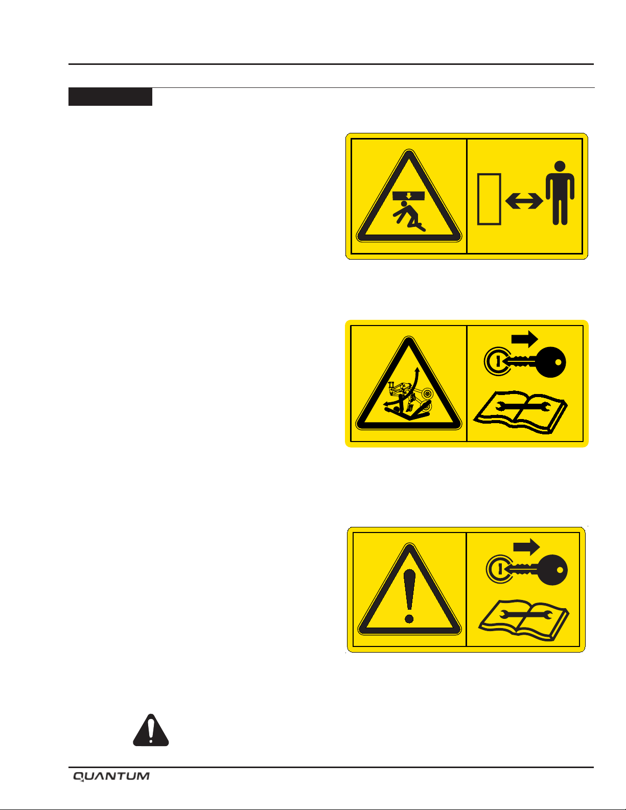
Safety Signs
Danger: Crushing Hazard
To prevent death or serious injury:
• Wings may fall rapidly causing bodily injury.
• Stand Clear - Of Wings when being raised, lowered
or in elevated state.
• Always install all Lockup devices provided when
wings are in elevated position.
• Ensure Cylinders are completely lled with hydraulic
uid to avoid unexpected movement.
Warning: Crushing Hazard
To prevent serious injury or death:
• Stand Clear - openers move rapidly under hydraulic
pressure.
• Stand Clear - Openers drop with full down force when
powering up or rebooting controller with hydraulics
engaged.
• Before servicing hydraulics - Lower openers to
ground and relieve pressure from hydraulic system.
• Shut tractor off and remove key before servicing or
adjusting depth.
• Place “Openers” valve in locked position before
adjusting depth or servicing.
Safety
S65153
S65155
Warning: Before Servicing
To prevent serious injury or death:
• Stop the tractor and remove key, read the service
specications at the back of this manual.
• Use lock-out tags/procedures as required to prevent
unanticipated machine operation.
• Do not operate with guard removed.
• Failure to comply could result in death or serious
S65151
injury
Familiarize yourself with the location of all decals. Read them
carefully to understand the safe operation of your machine.
January 2019 1-7
Page 12
Safety
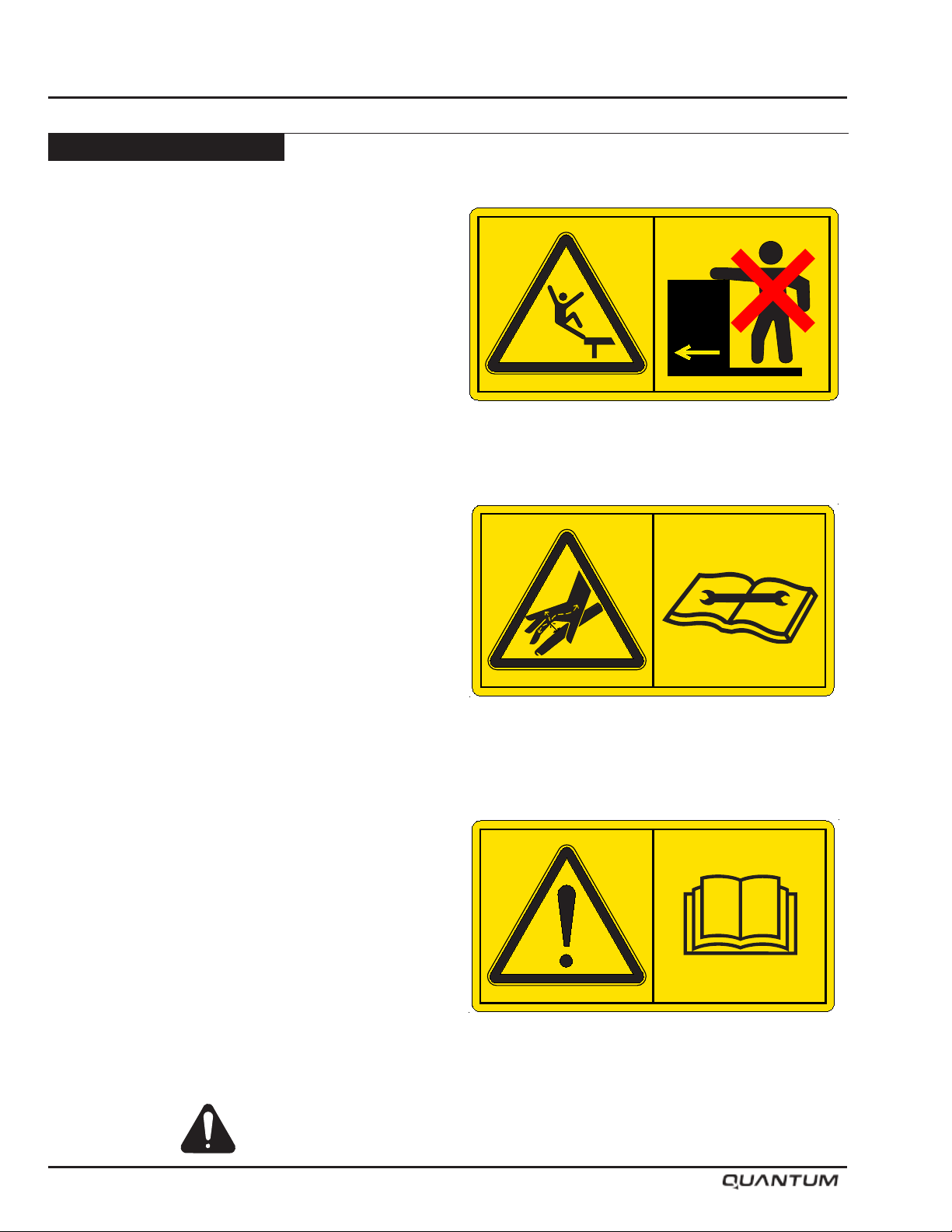
Safety Signs - Continued
Warning: No Riders
To prevent serious injury or death:
• Keep off while machine is moving or mechanism is
running.
Warning: HIGH-PRESSURE FLUID HAZARD
To prevent serious injury or death:
• Relieve pressure on hydraulic system before
servicing or disconnecting hoses.
• Wear proper hand and eye protection when
searching for leaks. Use wood or cardboard instead
of hands.
• Keep all components in good repair.
• Refer to tractor and implement Operator’s Manuals
service specications.
• Use lock-out tags/procedures as required to prevent
unanticipated machine operation.
S65154
S65152
Caution: Avoid injury!
Read and follow the instructions in this manual.
Failure to comply could result in minor or moderate
injury
Familiarize yourself with the location of all decals. Read them
carefully to understand the safe operation of your machine.
1-8 January 2019
S65150
Page 13
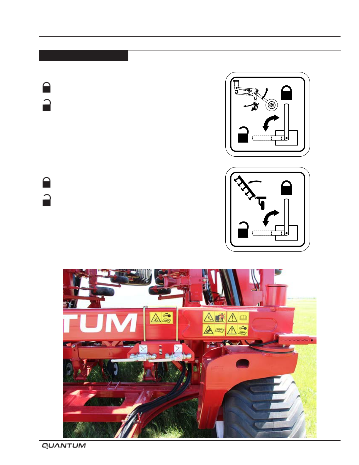
Safety Signs - Continued
Opener Hydraulic Lock
System is Locked-Out from Tractor Hydraulics
System is Open to Tractor Hydraulics
Wing Lift Hydraulic Lock
System is Locked-Out from Tractor Hydraulics
Safety
S65157
System is Open to Tractor Hydraulics
S65156
January 2019 1-9
Page 14
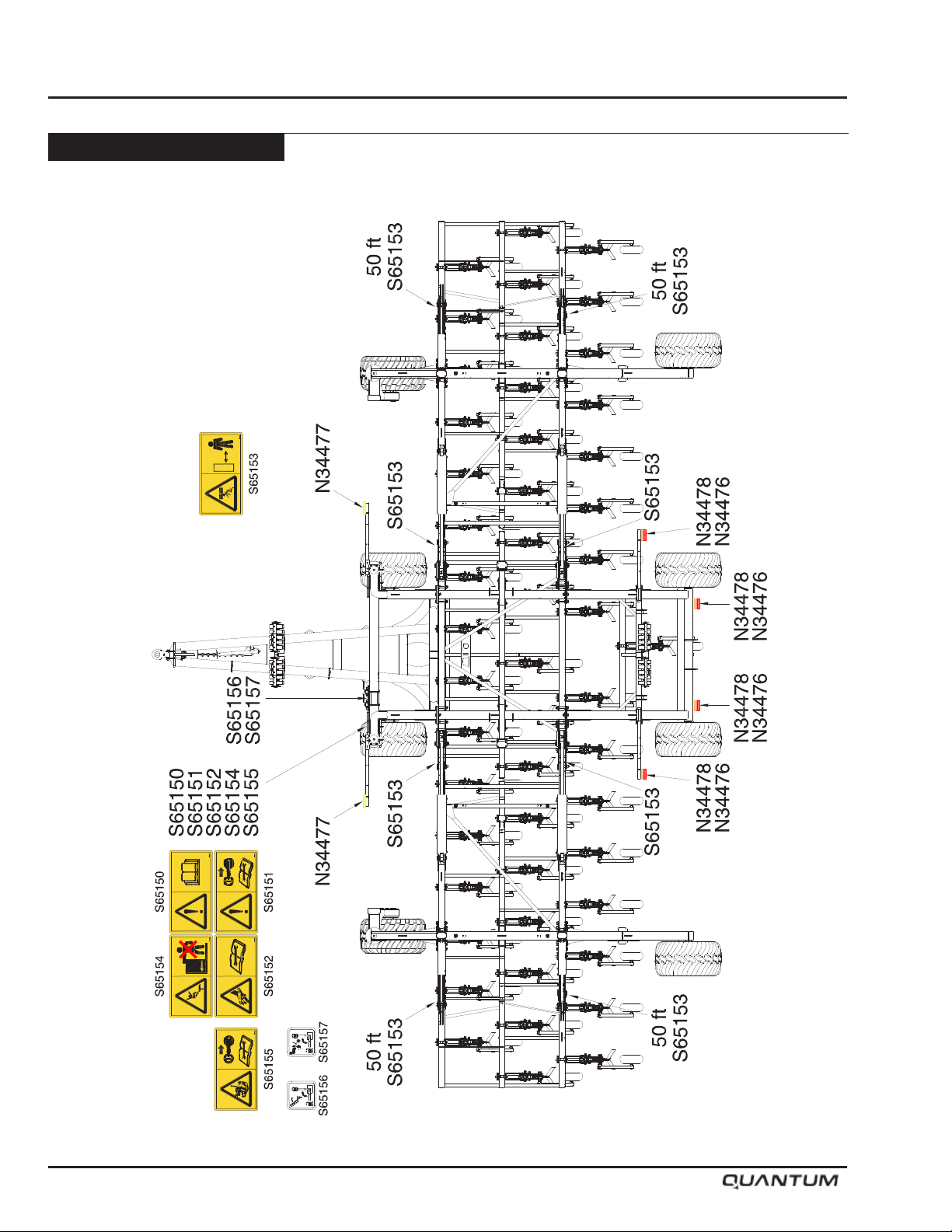
Safety
Safety Signs - Continued
Decal Locations - 40 and 50 Models
1-10 January 2019
Page 15
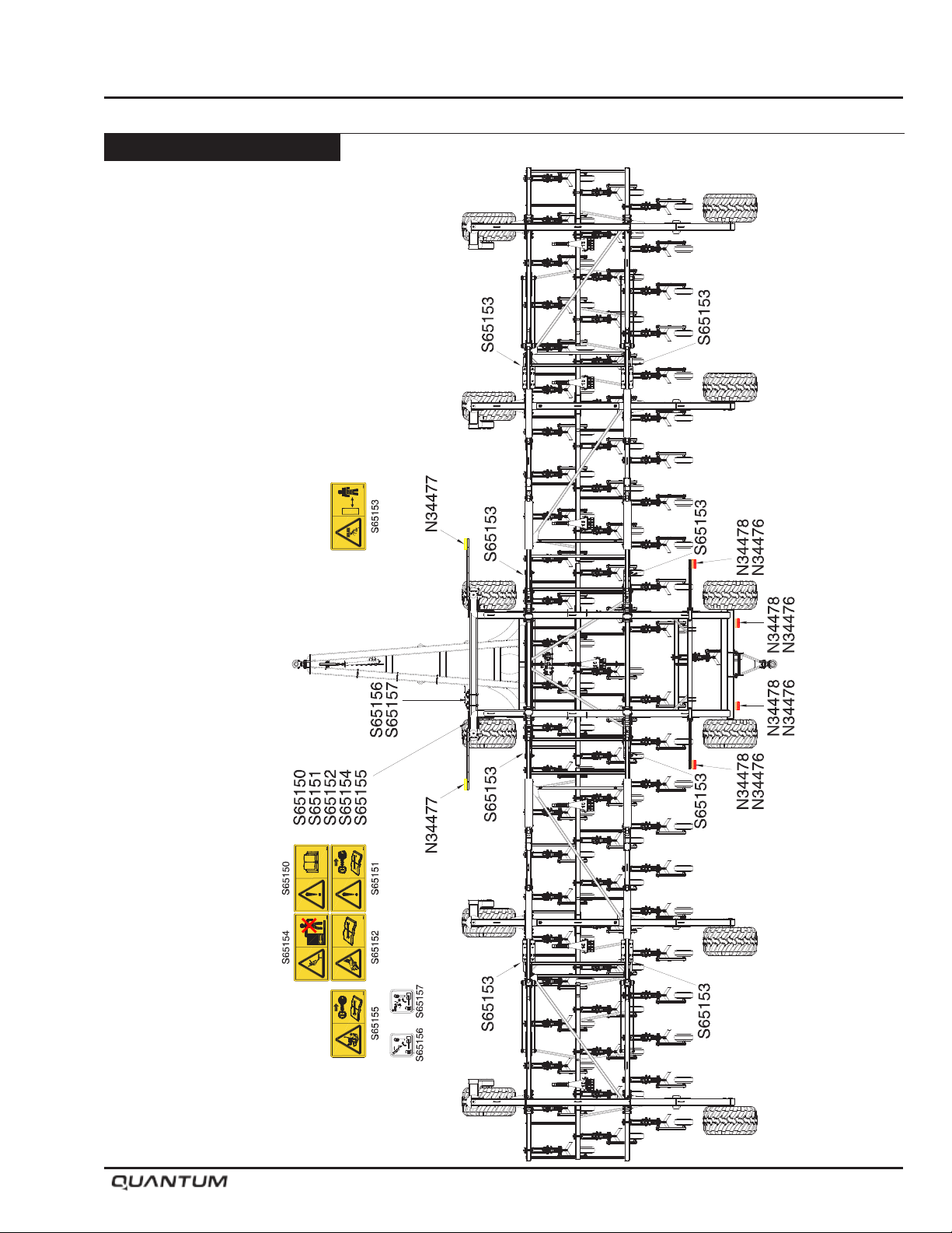
Safety Signs - Continued
Decal Locations - 60 and 70 Models
Safety
January 2019 1-11
Page 16
Safety
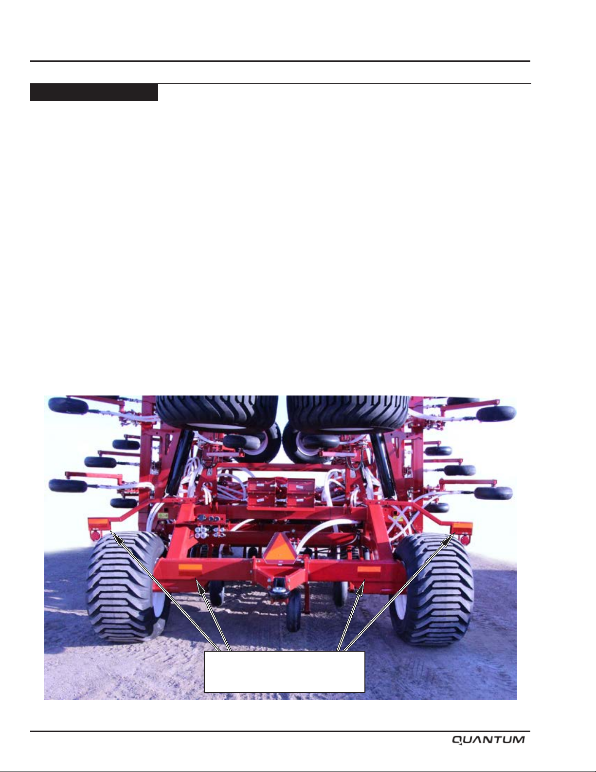
Lighting and Marking
MORRIS recommends the use of correct lighting and
marking to meet the ASAE standard for roadway travel.
Be familiar with and adhere to local laws.
Amber warning and red tail lights secured on the machine
promote correct transportation of this implement.
Note: Always replace missing or damaged lights
and/or connectors.
Amber warning and red tail lights must be mounted to
the rear of the implement and be visible from front and
rear. The lights must be within 16 inches (41 cm) of
the extremities of the machine and at least 24 inches
(60 cm) but not over 10 feet (3 m) above ground level.
Note: Always replace missing or damage front,
side, rear reectors and SMV emblem.
Rear View
N34478 - Orange Reflector
N34476 - Red Reflector
1-12 January 2019
Page 17
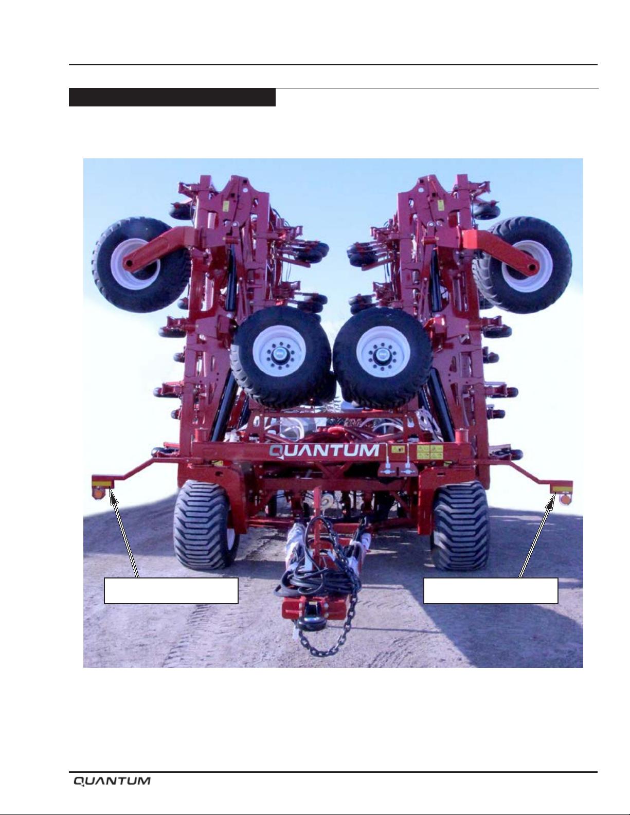
Lighting and Marking - Continued
Front View
Safety
N34477 - Yellow Reflector N34477 - Yellow Reflector
January 2019 1-13
Page 18
Safety
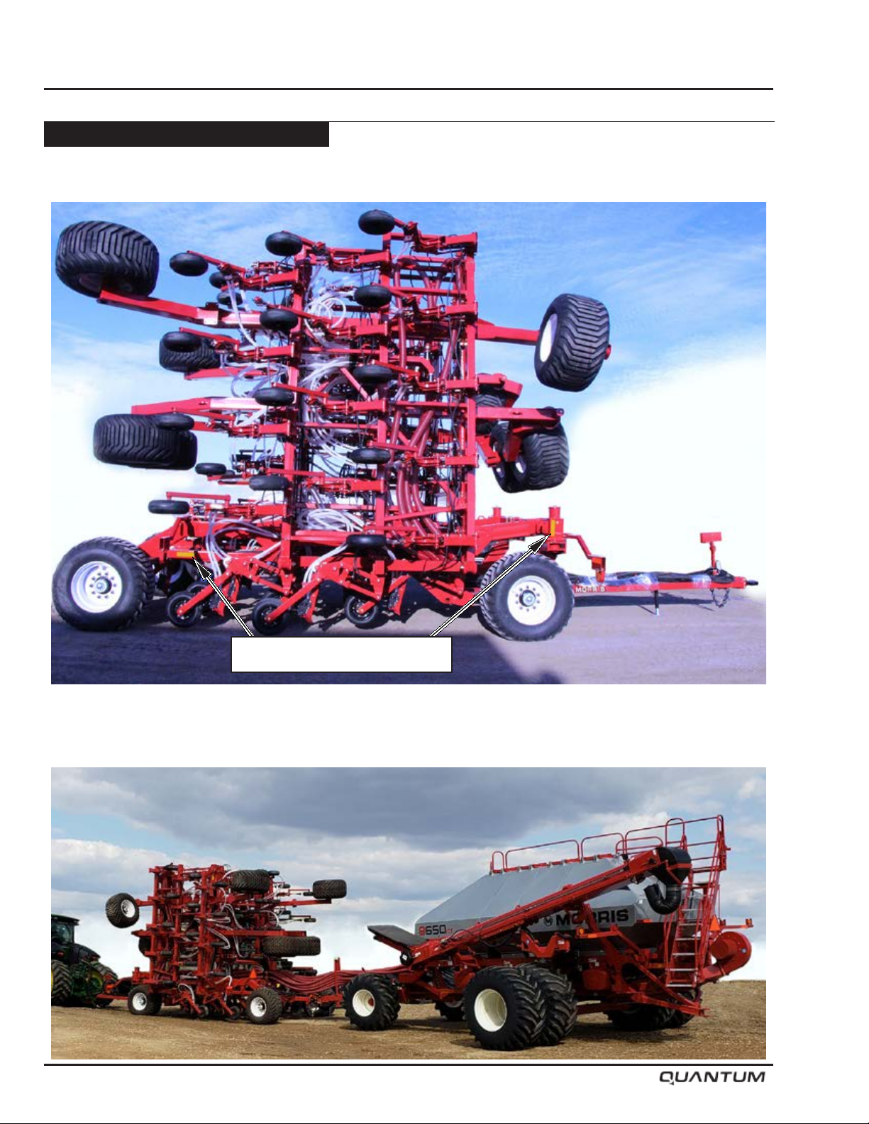
Lighting and Marking - Continued
Side View
N34477 - Yellow Reflector
1-14 January 2019
Page 19

Section 2: Specifications
Specifications
Section 2:
Specifications 2-1
Section Contents
Specifications and Options ...............................................................................................2-2
Transport Dimensions .......................................................................................................2-4
January 2019 2-1
Page 20
Specications
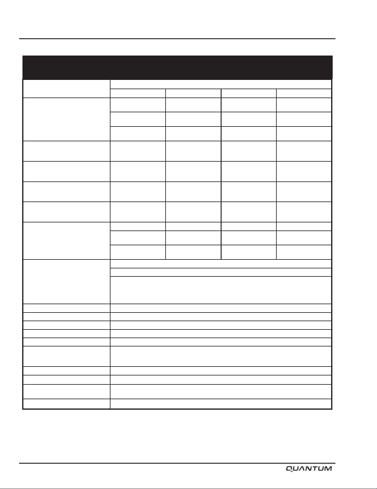
QUANTUM AIR DRILL
Specifications and Options
Base Size
Weight
(Includes Double
Shoot Distribution)
Working Width - 10” (250 mm)
Number of
Shanks
Frame Width - Main
Transport
Position
Tires - Main Frame Wheels (4) 600/50-22.5 (4) 600/50-22.5 (4) 600/50-22.5 (4) 600/50-22.5
Opener - Trip Out Force Maximum 800 lbs (363 kg) at 1200 psi (8274 kPa)
- 10” Spacing
250 mm Spacing
- 12” Spacing
300 mm Spacing
- 15” Spacing
380 mm Spacing
- 12” (300 mm)
- 15” (380 mm)
- 10” (250 mm)
- 12” (300 mm)
- 15” (380 mm)
- Wing Inner
- Wing Outer
- Width
- Height
- Length
- Wing Frame
Front Castor Wheels
- Wing Frame
Rear Wheels
- Packing Force 100 lbs to 230 lbs (45 kg - 104 kg)
- Packer Wheel
40’ or 12 m 50’ or 15 m 60’ or 18 m 70’ or 21 m
27,665 lb
12,549 kg
26,085 lb
11,832 kg
24,555 lb
11,138 kg
40’ or (12 m)
40’ or (12 m)
40’ or (12.16 m)
48
40
32
14.35’ (4.37m)
13.60’ (4.15m)
N/A
17’ 10” (5.44m)
16’ 10” (5.13m)
33’ 10”(10.31m)
Single Castor
(2) 600/50-22.5
(1 per wing)
(2) 600/50-22.5
31,970 lb
14,501 kg
30,030 lb
13,621 kg
28,050 lb
12,723 kg
50’ or (15 m)
50’ or (15 m)
50’ or (15.2 m)
60
50
40
14.35’ (4.37m)
13.60’ (4.15m)
5.03’ (1.53m)
17’ 10” (5.44m)
16’ 10” (5.13m)
33’ 10”(10.31m)
Single Castor
(2) 600/50-22.5
(1 per wing)
(2) 600/50-22.5
4.50” x 16” Semi Pneumatic Otico tire
Models
40,785 lb
18,500 kg
38,335 lb
17,388 kg
36,025 lb
16,341 kg
60’ or (18 m)
60’ or (18 m)
60’ or (18.24 m)
72
60
48
14.35’ (4.37m)
13.65’ (4.16m)
10.15’ (3.09m)
17’ 10” (5.44m)
16’ 10” (5.13m)
33’ 10”(10.31m)
Single Castor
(4) 600/50-22.5
(1 per wing)
(4) 600/50-22.5
44,090 lb
19,999 kg
41,210 lb
18,692 kg
38,530 lb
17,477 kg
70’ or (21 m)
70’ or (21 m)
70’ or (21.28 m)
84
70
56
14.35’ (4.37m)
15.65’ (4.77m)
13.16’ (4.01m)
17’ 10” (5.44m)
19’ 1” (5.82m)
33’ 10”(10.31m)
Single Castor
(4) 600/50-22.5
(1 per wing)
(4) 600/50-22.5
5.50” x 16” Semi Pneumatic Otico tire
5.50” x 16” Semi-Pneumatic
4.00” x 16” “V” Crown
Opener to Ground Clearance 12” (30.5 cm)
Frame to Ground Clearance 36” (91.4 cm)
Frame Depth 84” (213.4 cm) center to center
Rank to Rank Spacing 42” (106.7 cm) center to center
Number of Ranks 3 Rows
Shank to Shank Spacing 30” (750 mm) on 10” (250 mm) Spacing
Weight Kit Optional
Safety Lights Standard
Hitch Clevis Standard - Category 4
Safety Chain Standard
Specifications are estimates and subject to change.
36” (900 mm) on 12” (300 mm) Spacing
45” (1140 mm) on 15” (380 mm) Spacing
Optional - Category 5
2-2 January 2019
Page 21
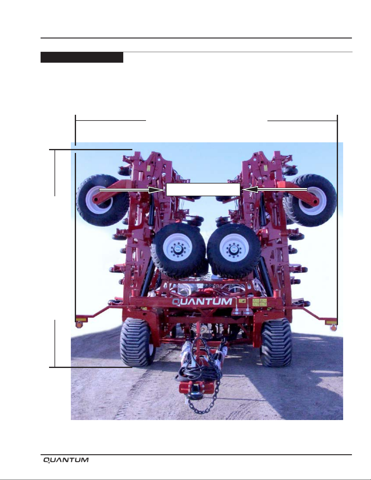
Transport Dimensions
Specications
WIDTH WITH PACKERS RETRACTED
(See Specications)
OPENERS RETRACTED
(See Specications)
HEIGHT WITH OPENERS RETRACTED
January 2019 2-3
Page 22

Specications
Notes
2-4 January 2019
Page 23

Section 3: Checklist
Checklist
Section 3:
Checklist 3-1
Section Contents
Manuals ............................................................................................................................3-2
Parts Manual .............................................................................................................3-2
Assembly Manual .......................................................................................................3-2
Checklist ...........................................................................................................................3-3
November 2018 3-1
Page 24
Checklist
SAFETY-ALERT
SYMBOL
Watch for this symbol. It identies
potential hazards to health or personal
safety. It points out safety precautions.
It means:
ATTENTION - BE ALERT.
Your safety is involved.
Manuals
Note: Pre-Delivery Inspection Form must be
completed and submitted to Morris Industries
within 30 days of delivery date.
Parts Manual
Assembly Manual
Order Part Number S66247
Order Part Number S66248 (Metric)
Order Part Number S66249 (Imperial)
Warranty Void if Not Registered
3-2 November 2018
Page 25

Checklist
Checklist
General
Please read the Operator’s Manual carefully
and become a “SAFE” operator.
Adopt a good lubrication and maintenance
program.
Check if assembled correctly.
Check hose connections.
Lubrication - Grease
Opener Wheel Hubs
Wheel Hubs
Castor Pivots
Tire Pressure
See tire chart in Maintenance, Section 6.
Transport
Tighten wheel bolts.
Check hose connections.
Ball valves are in locked position.
OWNER REFERENCE
Model:
Serial No:
Dealer:
Town: State:
Phone:
OWNER/OPERATOR
Date:
November 2018 3-3
TAKE SAFETY SERIOUSLY.
DO NOT TAKE
NEEDLESS CHANCES!!
Page 26

Checklist
Notes
3-4 November 2018
Page 27

Section 4: Introduction
Introduction
Section 4:
Introduction 4-1
Section Contents
Introduction .......................................................................................................................4-2
Active Hydraulic System ...................................................................................................4-3
January 2019 4-1
Page 28
Introduction
Introduction
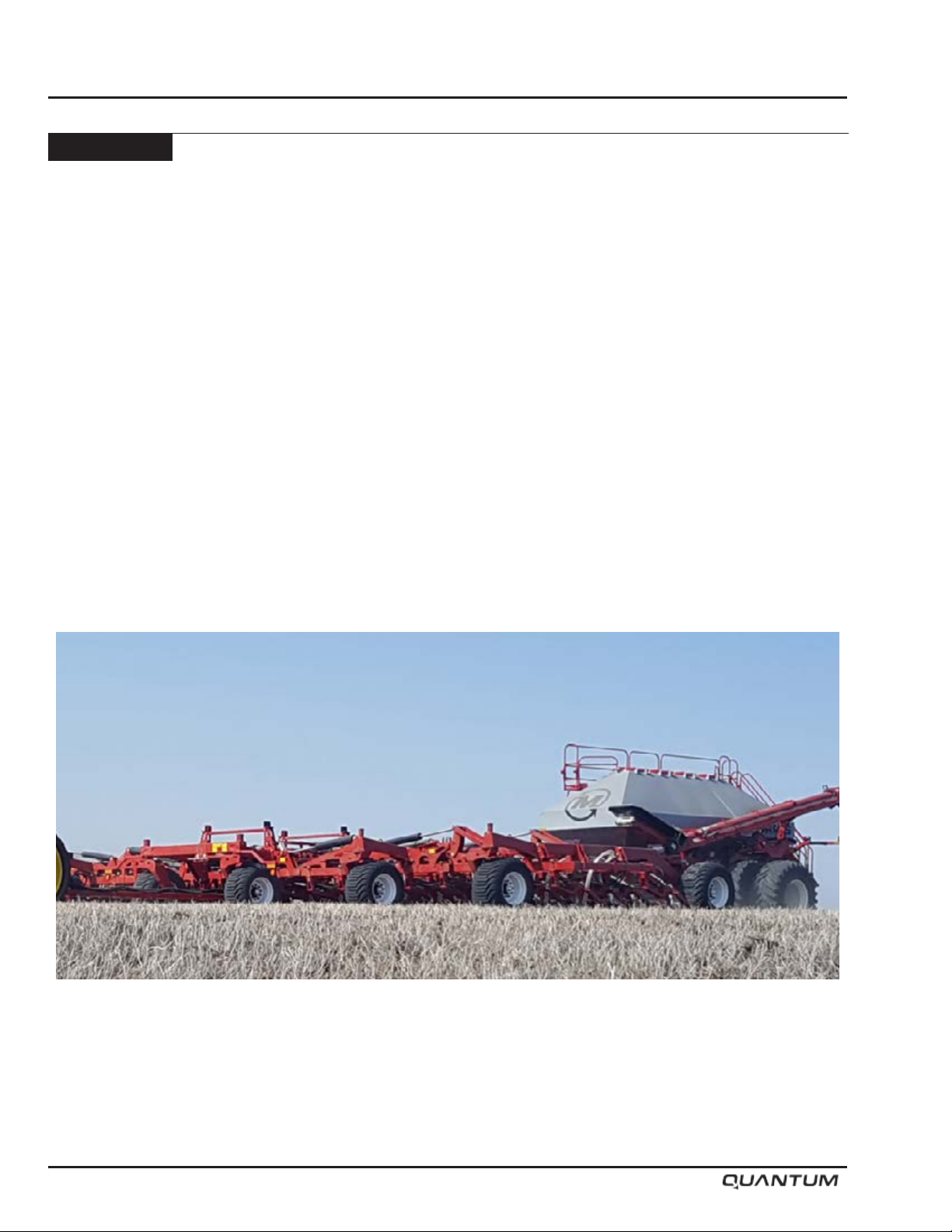
This Operator’s Manual has been carefully prepared
to provide the necessary information regarding the
operation and adjustments, so that you may obtain
maximum service and satisfaction from your new
MORRIS QUANTUM AIR DRILL.
To protect your investment, study your manual before
starting or operating in the eld. Learn how to operate
and service your QUANTUM AIR DRILL correctly, failure
to do so could result in personal injury or equipment
damage.
If you should find that you require information not
covered in this manual, contact your local MORRIS
Dealer. The Dealer will be glad to answer any questions
that may arise regarding the operation of your MORRIS
QUANTUM AIR DRILL.
MORRIS Dealers are kept informed on the best methods
of servicing and are equipped to provide prompt efcient
service if needed.
Occasionally, your QUANTUM AIR DRILL may require
replacement parts. Your Dealer will be able to supply you
with the necessary replacement parts required. If the
Dealer does not have the necessary part, the MORRIS
Factory will supply the Dealer with it promptly.
Your MORRIS QUANTUM AIR DRILL is designed to
give satisfaction even under difcult conditions. A small
amount of time and effort spent in protecting it against
rust, wear and replacing worn parts will increase the
life and trade-in value.
Keep this book handy for ready reference at all times. It is the policy of Morris Industries Ltd. to improve its
products whenever it is possible to do so. The Company reserves the right to make changes or add improvements
at any time without incurring any obligation to make such changes on machines sold previously.
4-2 January 2019
Page 29
Active Hydraulic System
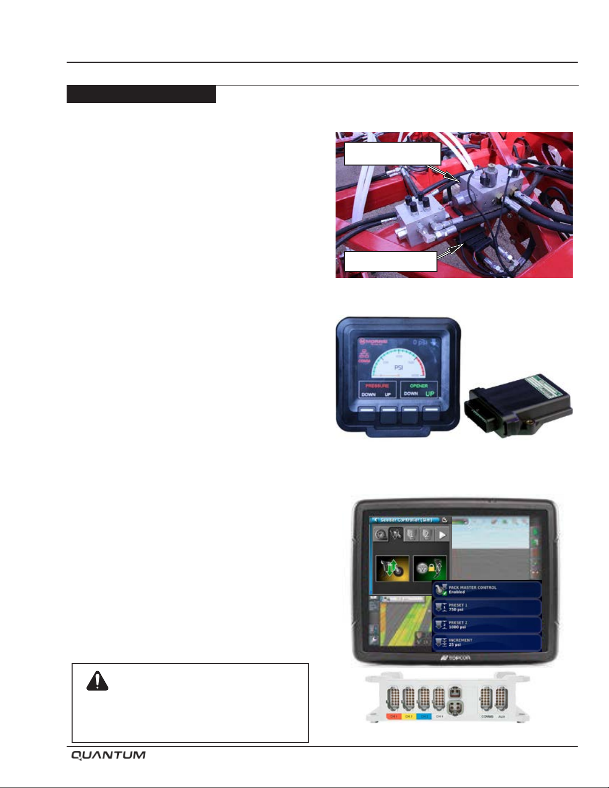
The active hydraulic system uses a special manifold
block (S64940) which controls the Lift-Lower and
packing pressure functions through a controller and an
in cab display.
The controller and display provides the user the ability
to adjust the opener downforce packing pressure on the
go from inside the cab while applying product.
As well as push button convenience to Lift and Lower
the openers from the Transport into the Working position.
Two control options are available to suit Ground Drive
and VRT/ICT style Air Carts.
a) JEM - CC PILOT and ESX Controller
b) Topcon - X35 Apollo CM-40 Master module
Option A:
Vansco equipped Ground Drive units must be congured
with a JEM CC Pilot Drill Control system package.
Introduction
Manifold - S64940
ESX Controller
Option B:
Topcon X35 Apollo equipped Air Carts (VRT, ICT) units
can be congured to use Apollo Lift Control / Pack
Control.
Topcon Apollo Equipped Air Carts can also control the
QUANTUM Lift/Lower functions and Pressure settings*.
Lift Control will automatically Lift/Lower the openers
when entering and exiting a headlands or previous
applied coverage.
*Note: Pack Control - (Opener Pressure Control)
requires a complete spare drive channel on
Apollo ECU. A 4 Tank Cart would require an
additional EM40.
JEM CC PILOT Display Screen and ESX Controller
Warning
Openers drop with full down force when
powering up or rebooting the controller with
hydraulics engaged.
January 2019 4-3
Topcon X35 Apollo - Lift Control / Pack Control
Page 30

Introduction
Notes
4-4 January 2019
Page 31

Section 5: Operation
Operation
Section 5:
Operation 5-1
Section Contents
Application ........................................................................................................................5-2
Tractor ...............................................................................................................................5-2
Hitching ............................................................................................................................5-3
Hitching to Tractor ......................................................................................................5-3
Unhitching from Tractor ..............................................................................................5-4
JEM CC Pilot Dispay Wiring .......................................................................................5-5
X35 Apollo - Lift and Pressure Control Wiring.............................................................5-6
Transport ...........................................................................................................................5-8
Transport to Field Position ..........................................................................................5-9
Field to Transport Position ......................................................................................... 5-10
Opener Hydraulic System .............................................................................................. 5-11
Operation ................................................................................................................. 5-11
Lifting/Lowering .....................................................................................................5-11
Pressure Setting ...................................................................................................5-12
Limp home mode (manual hydraulic operation) ....................................................5-12
Controller Options ...........................................................................................................5-13
JEM CC Pilot Dispay ................................................................................................5-13
Topcon - X35 Apollo .................................................................................................5-14
Lift Control Setup ..................................................................................................5-15
Hydraulic Pressure Control Setup ........................................................................5-18
Pack Control Setup ...............................................................................................5-23
Pack Control Calibration .......................................................................................5-28
Depth Adjustment ...........................................................................................................5-33
Work Switch ....................................................................................................................5-35
General Guidelines .........................................................................................................5-36
Quick Tips .......................................................................................................................5-37
Shank Trip Force .......................................................................................................5-37
Packing Force ...........................................................................................................5-37
Hydraulic System .....................................................................................................5-37
Lifting and Lowering the Openers ............................................................................5-37
Setting the Seed Depth ............................................................................................5-38
Seeding Conditions ..................................................................................................5-38
Straw Management ..................................................................................................5-38
Air Drill Frame ..........................................................................................................5-39
Wing Lift Hydraulics ........................................................................................................5-40
Opener Hydraulics .........................................................................................................5-42
January 2019 5-1
Page 32
Operation
CAUTION
BE ALERT
Application
The Morris QUANTUM DRILL utilizes independent
parallel link openers. Each opener moves independently
of the frame and each other to follow every contour of
the land closely. The unique design of the opener allows
the Morris QUANTUM DRILL to be used in a variety
of seeding applications from conventional to zero till
applications.
SAFETY FIRST
REFER TO SECTION 1 AND REVIEW ALL
SAFETY RECOMMENDATIONS.
Tractor
Tires
• Proper ballast and tire pressure are required when
pulling heavy implements.
• Consult your tractor operator’s manual and follow all
recommended procedures.
Hydraulics
• Wipe all hydraulic ttings and couplers with a clean
cloth to avoid contaminating the system.
• Check that hydraulic reservoir is lled to the proper
level.
Drawbar
• Centre and pin in a xed position for easier hitching
and greater stability.
Warning
Do not permit smoking, sparks or an open
flame where combustible fuels are being used.
Keep the work area well ventilated.
Warning
Do not search for high pressure hydraulic
leaks without hand and face protection. A tiny,
almost invisible leak can penetrate skin, that
requires immediate medical attention.
5-2 January 2019
Page 33
Hitching
Caution
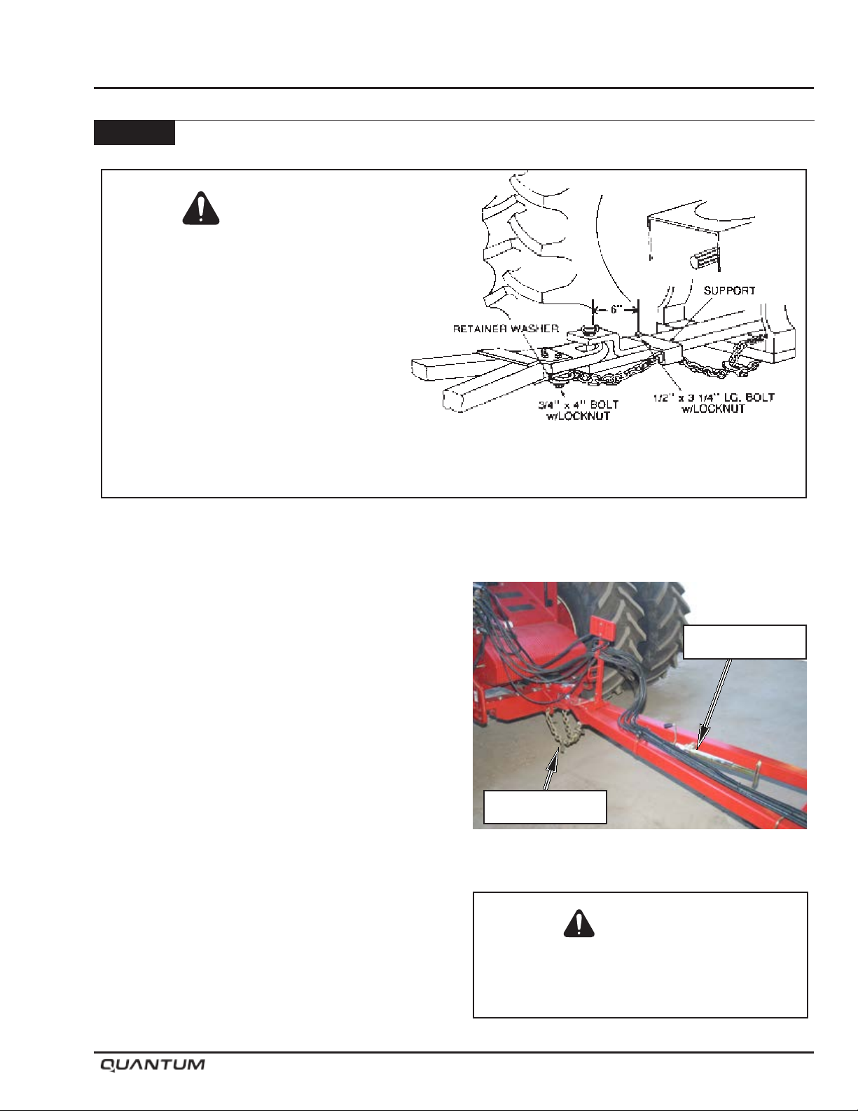
A safety chain will help control towed
machines should it accidentally separate
from the drawbar while transporting. A
runaway machine could cause severe injury
or death. Use a safety chain with a strength
rating equal to or greater than the gross
weight of the towed machines.
Operation
Attach safety chain to the tractor drawbar
support or other specified anchor location
with the appropriate parts.
Hitching to Tractor
• Ensure swinging drawbar is locked in the centre
position.
• Ensure hitch pin is in good condition.
• Level clevis with tractor drawbar using hitch jack.
• Back tractor into position and attach hitch clevis to
drawbar, using an adequate hitch pin.
• Lock hitch pin in place with a hairpin or other proper
locking device.
• After tractor to implement connection is made, relieve
pressure off the hitch jack.
• Place hitch jack in raised position.
• Route Safety Chain through chain support and
drawbar support.
• Lock safety hook onto chain.
Note: Provide only enough slack in chain to permit
turning.
• Ensure hydraulic hose quick couplers are dirt free.
• Inspect all ttings and hoses for leaks and kinks.
Repair as necessary
• Connect the hydraulic hoses to the tractor quick
couplers.
Hitch Jack
Safety Chain
Hitch Jack Raised
Caution
Dirt in the hydraulic system could damage
O-rings, causing leakage, pressure loss and
total system failure.
January 2019 5-3
Page 34
Operation
Hitching - Continued
Hitching to Tractor - Continued
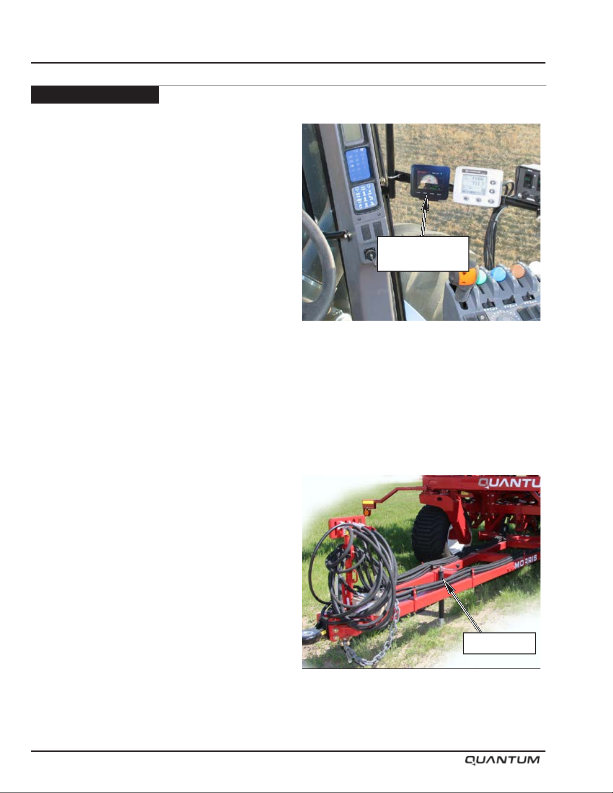
• Mount the JEM Display in tractor cab with the LCD
visible and with in easy reach to operate. See next
page for harness details.
• Route the JEM harness away from moving parts
and sharp protrusions. Connect the red wires to the
positive (+) terminal of the battery. Connect the black
wires to the negative (-) terminal of the battery.
• If equipped with a Topcon X35 Apollo system refer
to X35 Operator’s Manual. See page 5-6 and 5-7
for harness details.
• Tractor Hydraulics - set Opener hydraulics on
continuous with a flow rate of 25 GPM. Refer
to tractor manufactures information for optimal
plumbing of hydraulic system.
JEM Display
Pressure Gauge
Unhitching from Tractor
• Pin hitch jack in storage position.
• Lower hitch jack taking the weight off the hitch clevis.
• Ensure all transport locks are properly secured.
• Relieve pressure in the hydraulic hoses by positioning
tractor hydraulic lever in “oat” position or turn tractor
engine off and cycle lever back and forth several
times.
• Disconnect wire harnesses and hydraulic hoses.
• Remove the safety chain.
• Remove the drawbar pin.
• Slowly move tractor away from Air Drill.
Hitch Jack
Hitch Jack Lowered
5-4 January 2019
Page 35
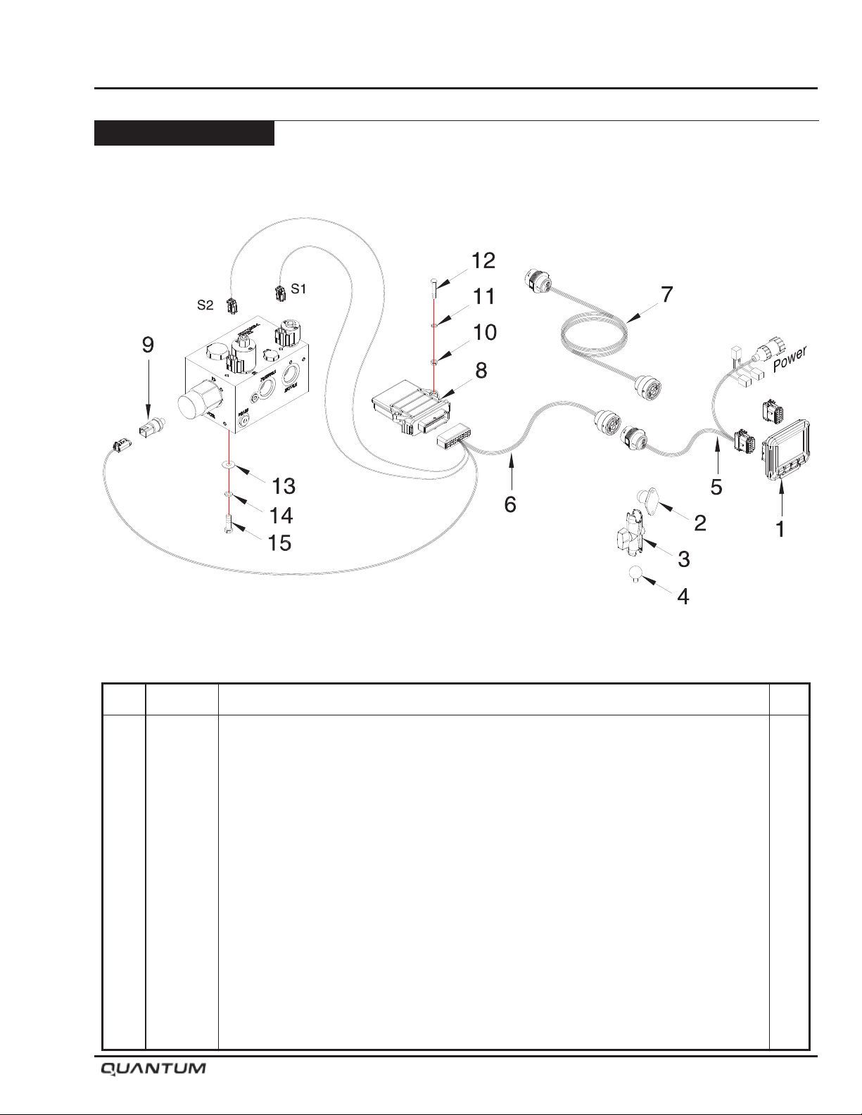
Hitching - Continued
JEM CC Pilot Dispay Wiring
Operation
Item Part No. Description Qty
1 N65145 CC Pilot Display - 3 1/2 Full Color ..................................................................................... 1
2 N65146 Ram Mount - 1 7/16 x 1 5/16 ............................................................................................. 1
3 N65147 Ram Short Arm ................................................................................................................. 1
4 N65148 Ram Ball - 1 Diameter ....................................................................................................... 1
5 N65141 Harness - Tractor (1000545) .............................................................................................. 1
6 N65142 Harness - Implement (1000546) ....................................................................................... 1
7 N65149 Harness - Extension (Tow Between Carts) (1000626) ...................................................... 1
8 N65143 ESX-10Xp ECU ................................................................................................................. 1
9 K62977 Pressure Transducer .......................................................................................................... 1
10 W-512 Hex Nut - 1/4 ..................................................................................................................... 2
11 W-521 Lockwasher - 1/4 ............................................................................................................... 2
12 C-1471 Hex Bolt - 1/4 x 1 3/4 Lg.................................................................................................... 2
13 W-538 Flatwasher - 7/16 ID x 1 OD x 14 GA ................................................................................ 4
14 W-523 Lockwasher - 3/8 ............................................................................................................... 4
15 W-475 Hex Bolt - 3/8 x 1 Lg.......................................................................................................... 4
N65140 CC Pilot Display Kit - (Includes Items 1 to 4)
January 2019 5-5
Page 36
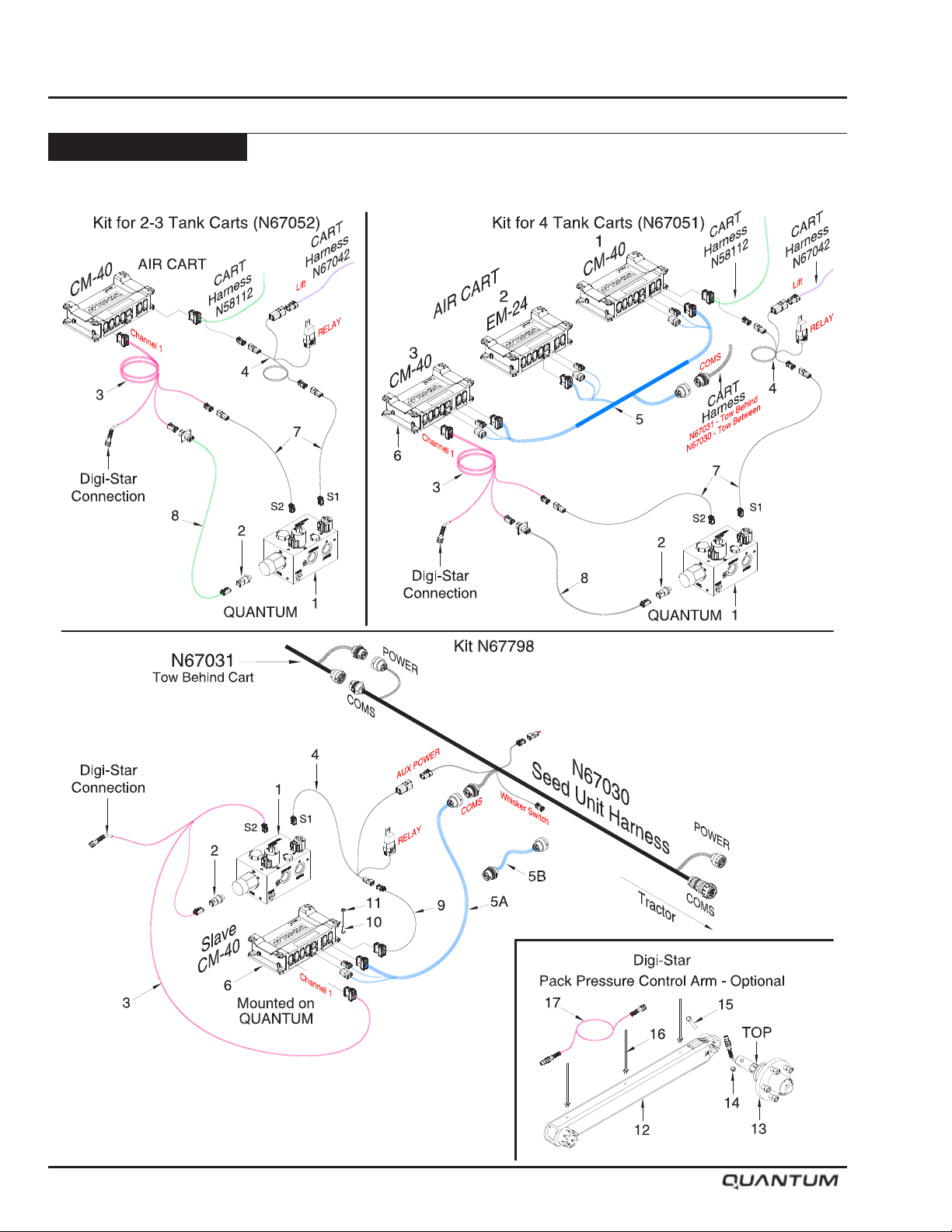
Operation
Hitching - Continued
X35 Apollo - Lift and Pressure Control Wiring
5-6 January 2019
Page 37
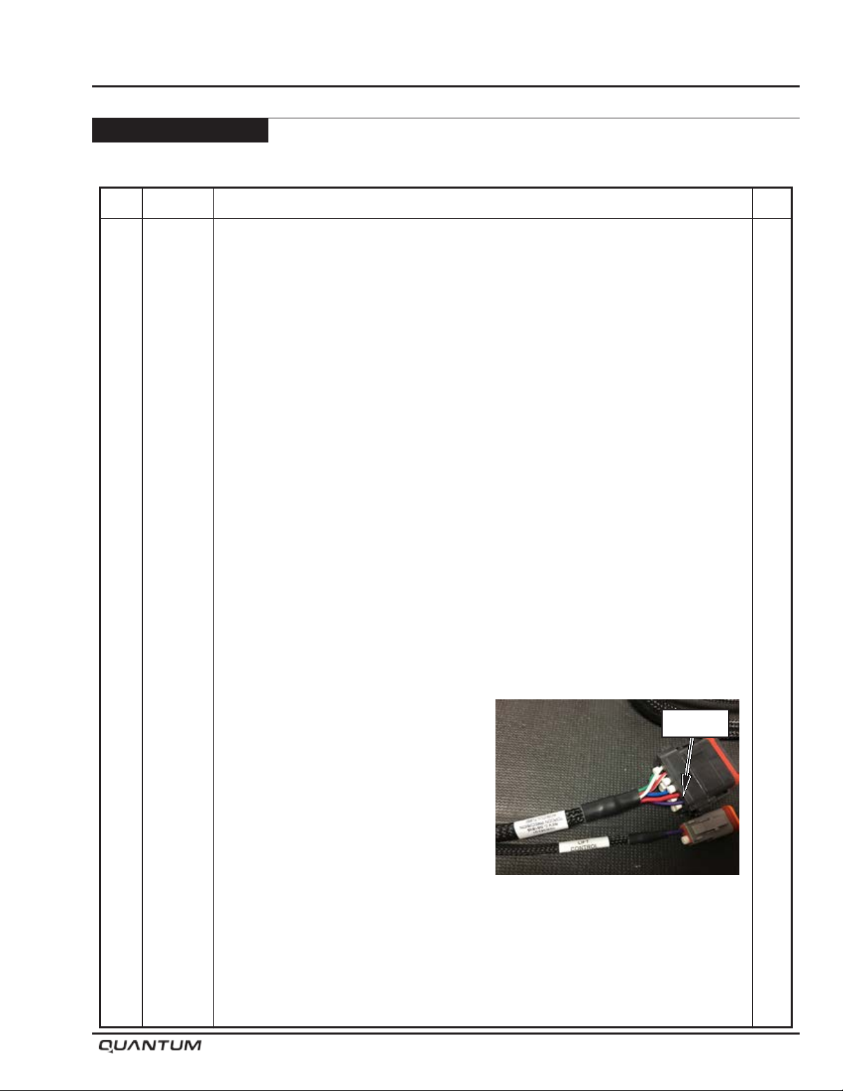
Operation
Hitching - Continued
X35 Apollo - Lift and Pressure Control Wiring - Continued
Item Part No. Description Qty
1 S64940 Manifold - Opener Control ................................................................................................. 1
2 K62977 Pressure Transducer .......................................................................................................... 1
3 N67045 Harness - Pack Control (1026291-01) ............................................................................... 1
4 N67046 Harness - Lift Control (1006258-01) .................................................................................. 1
5 N67037 Harness - Triplex ECU Adapter (1005038-01) .................................................................... 1
5A N67038 Harness - Single ECU (1005036-01) ................................................................................. 1
5B N68000 Harness Extension - 2m - (1028492-01) - Optional
6 N55950 Apollo Master Module ECU - CM-40 - (AGA5339) ............................................................ 1
7 N59010 Harness Extension - Work Switch - 5m - (AGA4468) ........................................................ 2
8 N64671 Pressure Transducer Extension Harness - 7m - (1024230-01) .......................................... 1
9 N68001 AUX Lift Lower Signal Adapter .......................................................................................... 1
10 W-187 Hex Bolt - 3/8 x 1 1/4 Lg - Bolts ECU to plate under manifold .......................................... 4
11 D-5279 Locknut - 3/8 Serrated Flange ........................................................................................... 4
N67052 Lift and Pressure Control Kit for 2-3 Tank Carts (Includes Items 3, 4, 7 and 8)
N67051 Lift and Pressure Control Kit for 4 Tank Carts (Includes Items 3, 4, 5, 6, 7 and 8)
N67798 Lift and Pressure Control Kit for 4 Tank Carts Tow Behind ONLY
(Includes Items 3, 4, 5A, 6, 9, 10 and 11)
Pack Pressure Control Arm - Optional
12 S66267 Packer Arm - Digi-Star ...................................................................................................... 1
13 S67715 Axle Assembly - Digi-Star (Includes S66278 Spindle - Digi-Star) ..................................... 1
14 M-3388 Lock Nut - 3/8 Unitorque ................................................................................................... 1
15 W-479 Hex Bolt - 3/8 x 2 1/4 Lg.................................................................................................... 1
16 S67885 Zip Tie - Push Mount ......................................................................................................... 3
17 N68002 Extension Cable - Optional
S67716 Pack Pressure Control Arm Assembly (Includes Items 12, 13, 14, 15 and 16)
Pin 13
X35 Apollo - Wiring
Ensure the Single Purple wire is installed in pin 13 (Relay signal out on the Auxiliary
harness) as shown. (Cart Harness N58112)
Connect 1006258-01 Lift lower harness to the following connections:
Trunk /Whisker - to the single wire connection to pin 13 on Aux harness
Relay Power - to AGA5343 ECU harness DTP power connector - (remove dust cap).
Lift Solenoid - to S1 on JEM Manifold block on Quantum drill
January 2019 5-7
Page 38
Operation
Transport
Observe all applicable safety precautions under
transport heading in Safety, Section 1.
• Refer to Specifications, Section 2, for weight,
transport height, and width.
• Transport with tractor only!
• Ensure safety chain is attached correctly to the
towing vehicle and the hitch of the implement.
• Inspect tires for any serious cuts or abrasions. If
such has occurred, tire should be replaced.
• Raise and lower wings on level ground.
• Never raise or lower wings when moving.
Speed
• Always travel at a safe speed. Do Not Exceed 20
mph (32 kph).
• The weight of the implement being towed must not
exceed 1.5 times the weight of towing vehicle.
MORRIS INDUSTRIES LTD. WILL NOT BE
RESPONSIBLE FOR ANY DAMAGES OR
OPERATOR INJURY RESULTING FROM NONUSE OR IMPROPER USE OF TRANSPORT
LOCKS.
Caution
Raise and lower wings on level ground. Never
raise or lower wings when moving.
Lights
• Ensure proper reectors are in place, refer to Safety,
Section 1.
• Use ashing amber warning lights, turn signals and
SMV emblems when on public roads.
• Be familiar with, and adhere to, local laws.
5-8 January 2019
Page 39
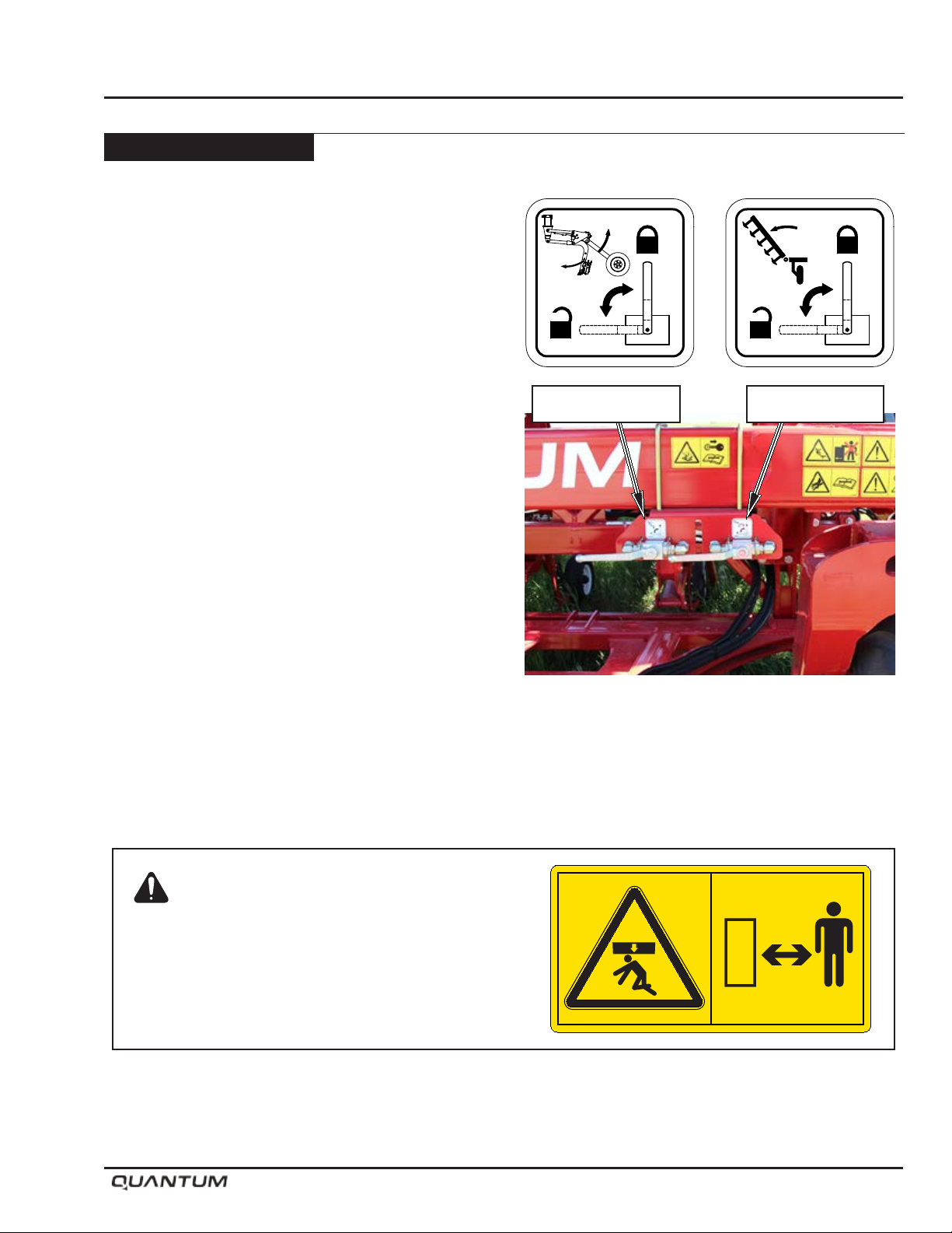
Transport - Continued
Transport to Field Position
• Position machine on level ground.
• Stop tractor, and engage park brake.
• As a precaution, check surrounding area to be sure
it is safe to lower wings.
• Unlock the wing valve and opener valve. Do not walk
under raised wings.
• Operate opener hydraulics, to ensure all openers are
retracted.
• Operate wing lift hydraulics until wings are lowered
and the cylinder shafts are completely extended to
allow wings to oat when working in uneven land.
Never raise or lower wings when moving.
Note: When raising or lowering wings, do so in one
continuous motion until fully up or down. Do
not stop ow part way allowing wings to fold
on their own. This may disrupt the sequence
of operation.
Operation
S65157
Openers Valve Wing Valve
S65156
Danger: Crushing Hazard
To prevent death or serious injury:
Always stay clear of wings being raised, lowered or
in elevated position. Ensure cylinders are completely
filled with hydraulic fluid - wings may fall rapidly
causing injury or death.
Valves in Unlocked Position
S65153
January 2019 5-9
Page 40
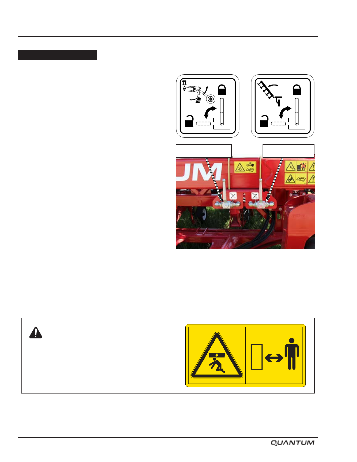
Operation
Transport - Continued
Field to Transport Position
• Position machine on level ground.
• Stop tractor, and engage park brake.
• Ensure wing lift cylinders are fully extended.
Note: The wing lift cylinders must be fully extended
to ensure proper operation of the flow
control valve (FCV) manifold.
• Operate the opener hydraulics, to raise the openers
fully.
• Operate the wing lift hydraulics, to raise the wings
fully into transport position. Never raise or lower
wings when moving.
Note: When raising or lowering wings, do so in one
continuous motion until fully up or down. Do
not stop ow part way allowing wings to fold
on their own. This may disrupt the sequence
of operation.
• Lock wing lift valve and opener valve. Do not walk
under raised wings.
• Ensure safety chain is properly installed, see
“Hitching to Tractor” of the Operation Section.
S65157
Openers Valve Wing Valve
S65156
Danger: Crushing Hazard
To prevent death or serious injury:
Always stay clear of wings being raised, lowered or
in elevated position. Ensure cylinders are completely
filled with hydraulic fluid - wings may fall rapidly
causing injury or death.
Valves in Locked Position
S65153
5-10 January 2019
Page 41
Opener Hydraulic System
Operation
Basic function of the system:
• Tractor remote is set to continuous ow connected
to the “Pressure” port on the Opener Control Block.
• Control the Lift-Lower and packing pressure functions
through JEM display or X35 monitor.
WARNING: Openers will drop with full operating
force if the JEM display or X35 monitor is
rebooted with hydraulics running.
• Flow requirements during operation will be minimal in
most conditions (3-4 GPM max) (11-15 lpm) but large
changes in terrain (drainage ditches, terraces, water
runs) will cause larger ow rates for short intervals.
Minimum oil ow rate for the opener circuit would
be 18 GPM (68 lpm); 25 GPM (95 lpm) is optimal.
Lower ow rate = slower operation on headlands.
Flow requirements are highest while lifting/lowering
openers at headlands.
Operation
Lifting/Lowering
• Flow can be set to as much as the tractor can provide
without losing too much fan speed during lifting and
lowering of the openers.
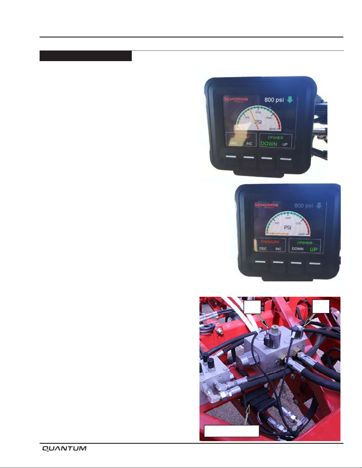
• Pressing Opener “UP” button on the controller will lift
the openers fully up by shifting solenoid valve “S1”
to gland side of opener cylinders.
• Pressing Opener “DOWN” button on the controller will
lower the openers all the way down and lock them
into working position by shifting solenoid valve “S1”
to its default position of ow straight through to butt
end of opener cylinders.
WARNING: Default valve position is openers
down when applying ow at “Pressure” port.
• The system will remember the last mode (“UP” or
“DOWN”) that it was operating in and operate in that
same mode at next start up.
Note: If the controller is not present or connected,
the tractor remote can be used manually
to lift and lower the openers although no
pressure control will be available; pressure
down will be limited to the default of the
reducing relieving valve “S2” (200 psi)(1379
kPa).
S2
S1
ESX Controller
January 2019 5-11
Page 42
Operation
Opener Hydraulic System - Continued
Operation - Continued
Pressure Setting
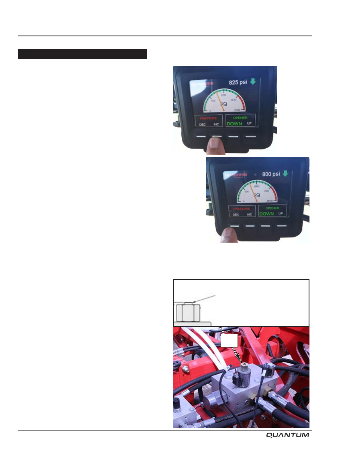
• Pressure can be adjusted on the go from the tractor
cab using the display.
• Pressing the Pressure “INC” button on the display
will increase the pressure by shifting proportional
reducing/relieving valve S2 in the block; each press of
the arrow will lift the pressure value by approximately
25 psi (172 kPa).
• Pressing the Pressure “DEC” button on the display
will decrease the pressure by shifting proportional
reducing/relieving valve S2 in the block; each
press of the arrow will drop the pressure value by
approximately 25 psi (172 kPa).
• The system will remember the last pressure setting
that it operated at and revert to that at next start up.
• To determine the approximate trip out force in pounds
on each shank, divide the system hydraulic pressure
in the circuit by 1.5.
For example: A system hydraulic pressure of 750 psi
(5171 kPa) would be approximately 500 lbs (227 Kg)
trip force at each shank.
Note: Due to the variation of friction effects, this
trip force is approximate.
Limp home mode (manual hydraulic operation)
If a situation arises where electronic control of the
opener hydraulics is not possible, a manual operation
mode can be used temporarily. In this mode, the tractor
hydraulics will need to be utilized to actuate lifting and
lowering of the openers. Tractor remote would need to
be set for continuous ow in the openers down operation
mode the same as when the electronic controls are
working. However, for lifting at headlands, the tractor
remote would be operated in the opposite direction to
lift the openers.
Pressure setting would then be done manually at the S2
Pressure Reducing/Relieving Valve. Turn the 3/16” hex
adjustment Clock Wise to increase pressure.
Note: Pressure adjustment on the go is not
possible while using “limp home mode”.
Manual Override
Turn 3/16 hex adjustment
Clock Wise to increase pressure.
S2
5-12 January 2019
Page 43
Controller Options
Two control options are available to suit Ground Drive
and VRT/ICT style Air Carts.
a) JEM - CC PILOT and ESX Controller
b) Topcon - X35 Apollo CM-40 Master module
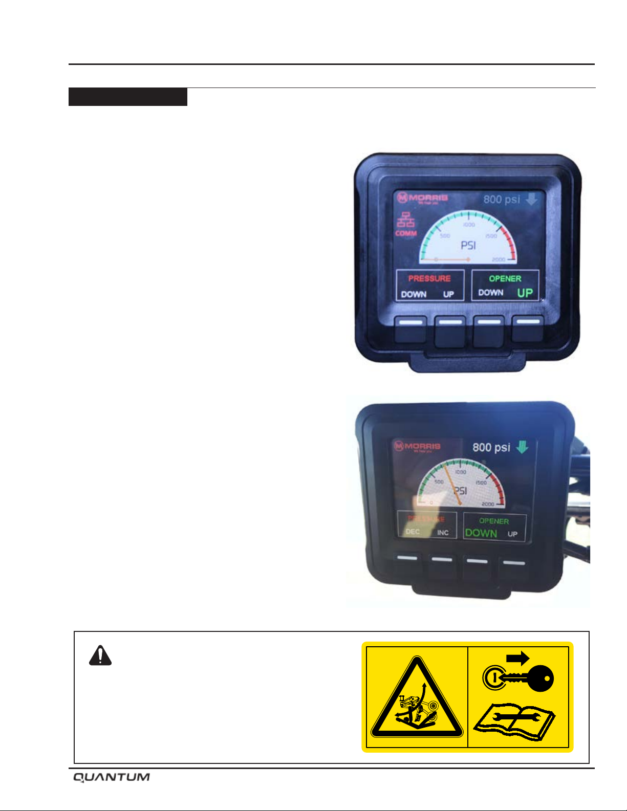
JEM CC Pilot Dispay
Opener: (S1) Opener valve is either Up / Down
Pressure: (S2) Pressure Reducing valve set point
adjusted by pressing the INC / DEC keys.
PSI Digital: Displays user target pressure setting.
Note: Pressure is adjusted by 25 psi (172 kPa)
increments. Up / Down arrows changes
depending on the button pressed.
PSI Analogue Gauge: Displays actual system
pressure from Pressure Transducer K62977.
Operation
Comm: Icon is only visible when there is no
communication with the ESX Controller.
Features:
• CC Pilot holds the last pressure used, example if the
last entered pressure was set at 800 psi (5516 kPa)
from the previous day upon powering on the unit the
value will return automatically to the last value used
of 800 psi (5516 kPa).
Warning: Openers drop with full down force when
powering up or rebooting controller
with hydraulics engaged.
• Buzzer alarms when Pressure exceeds 1500 psi.
(10342 kPa) (alarm is not user settable)
• White Gauge Face changes to Black when work
lights are turned on, requires remote wire attached.
Warning
Openers drop with full down force when
powering up or rebooting the controller with
hydraulics engaged.
S65155
January 2019 5-13
Page 44
Operation
Controller Options - Continued
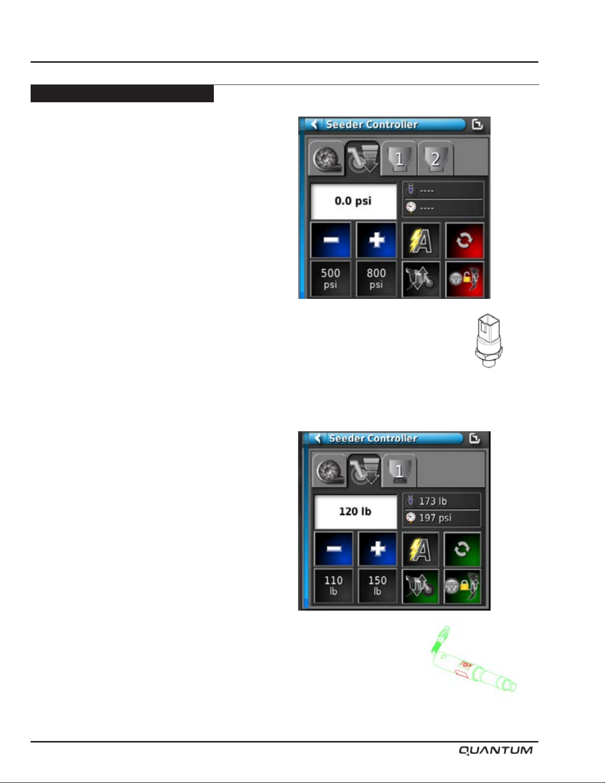
Topcon - X35 Apollo
The X35 Apollo system provides two operating modes
depending on the drill conguration:
1. Lift Control and Hydraulic Pressure Control
The target Hydraulic Pressure is entered into the X35
monitor. Once the desired hydraulic pressure is set,
the Topcon control loop analyzes the signal from the
Transducer and will increase / decrease the hydraulic
pressure of the S2 solenoid to maintain the requested
Target.
VR/ICT Base System (All Topcon equipped Morris Air
Carts) - pressure control and auto headland lift/lower
functionality.
• Proportional pressure control for split second
pressure control to maintain pressure even in rapidly
changing terrain.
• Automatically lift and lower openers in the headlands.
• Float mode to remove pressure from openers for soft
or muddy conditions.
• Potential to upgrade the system to Packer Force
Control as an add on kit.
2. Packer Pressure Control
Quantum drills equipped with the Topcon Pack Control
option include a new packing arm [S67716]. The
arm consists of a special Digi-Star spindle assembly
[S67715] which is capable of measuring the downforce
being applied onto the Packing Wheel.
The target Packing Force is entered into the X35 monitor.
Once the desired Packing Force is set, the Topcon
control loop analyzes the ADC signal from the Spindle
and will increase / decrease the amount of hydraulic
pressure of the S2 solenoid to maintain the requested
Packing Force Target.
VR/ICT Packer Force Control (Option) - can control /
maintain a set amount of pressure on the packer tire of
the row unit via a load cell sensor and closed loop control
• All of the capabilities of Hydraulic Pressure Control
with the added control function of maintaining/
controlling packer force for variable eld conditions
in order to improve depth control and product
placement as well as rmness of the soil in the furrow.
Note: Operator will have to be aware of changing
soil conditions across drill as Load Cell
maybe in softer or harder soil than the rest
of the drill.
5-14 January 2019
Page 45
Operation
Controller Options - Continued
Topcon - X35 Apollo - Continued
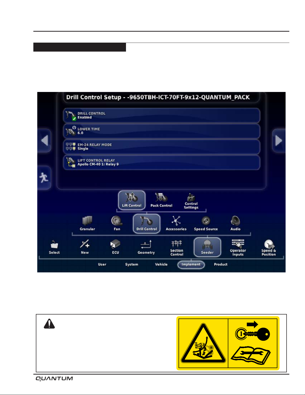
Lift Control Setup
In order to run Pressure Control or Pack Control, Lift Control must be setup rst.
In the set-up Menu go to: Implement - Seeder - Drill Control - Lift Control
Drill Control - Enabled
Lower Time - 6 seconds (user adjustable). This is the time required for all the openers to lower before entering
unseeded ground.
Warning
Openers drop with full down force when
powering up or rebooting the X35 with
hydraulics engaged.
S65155
January 2019 5-15
Page 46
Operation
Controller Options - Continued
Topcon - X35 Apollo - Continued
Lift Control Setup - Continued
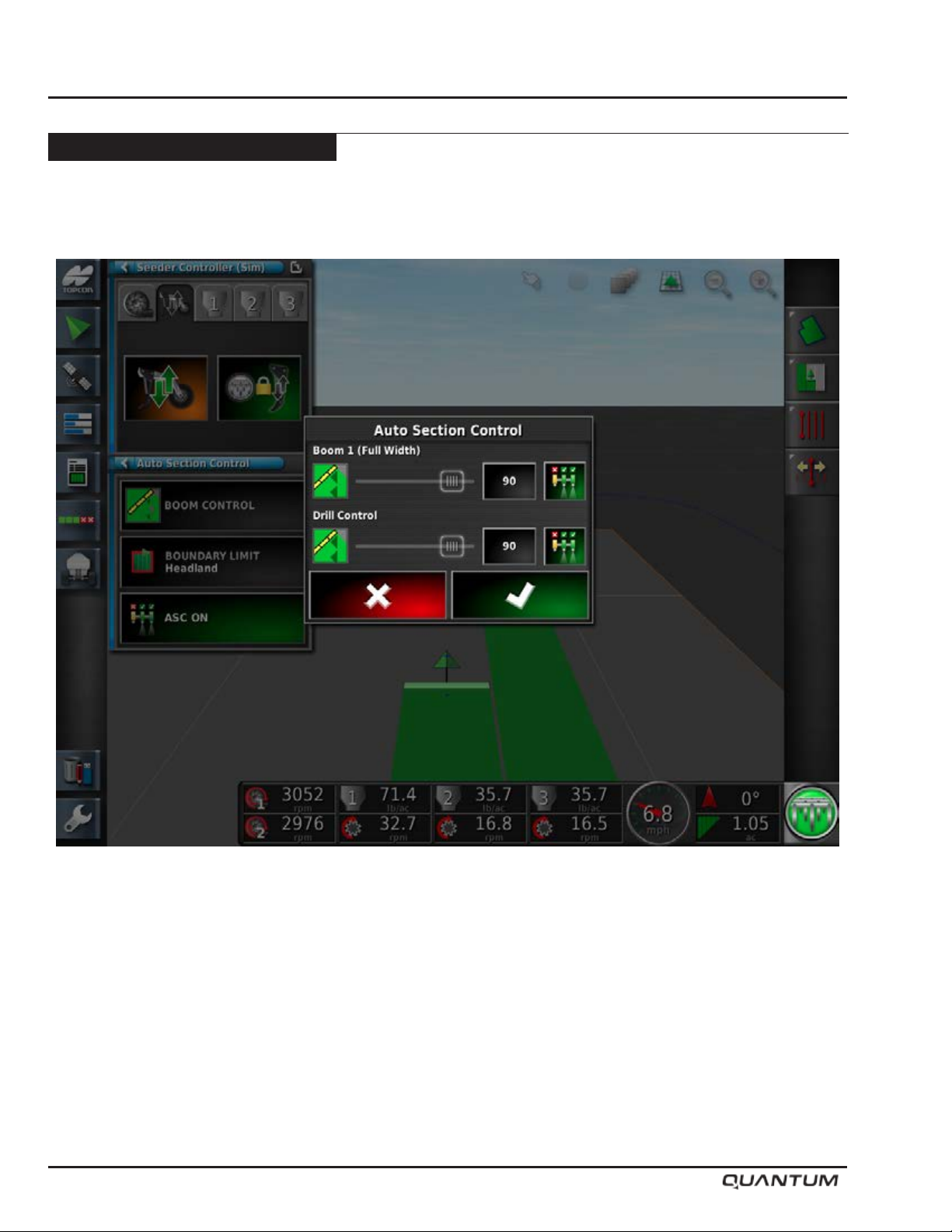
Adjust the ASC so the ICT boom and Drill control match.
5-16 January 2019
Page 47
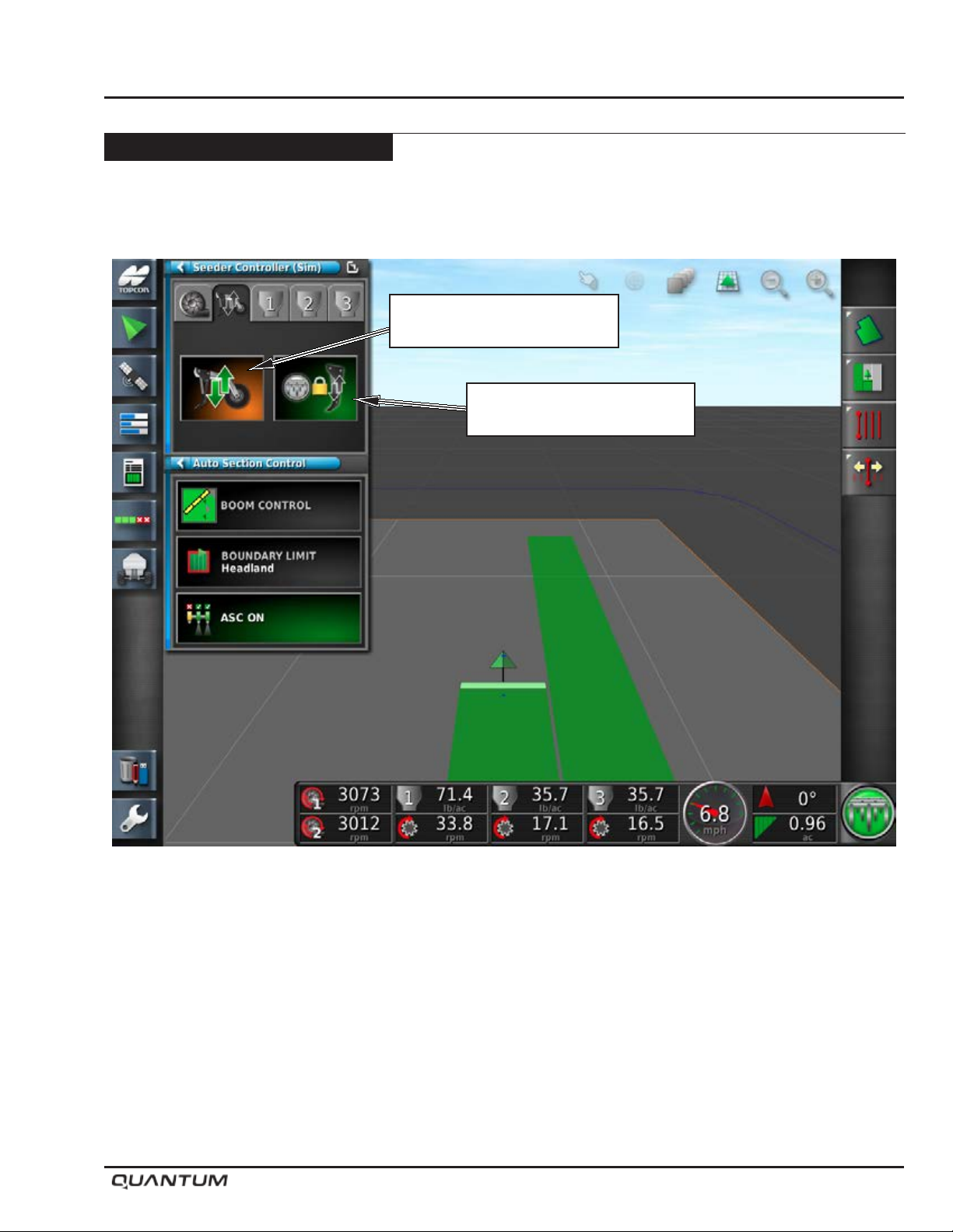
Controller Options - Continued
Topcon - X35 Apollo - Continued
Lift Control Setup - Continued
Operation
Lift Control (Up / Down)
Over Ride
Drill Track Control
(Auto Lift)
Lift Control will work on both Virtual headlands and previous coverage, where the unit would normally turn off all
sections, will now auto lift and lower the drill.
Lift Control can be used to manually control the drill - Lift (Red Arrows) and Lower (Green Arrows).
Track Control is used to set whether the Lift Control will track the master state or not.
1. In ON state (Green) the drill position will follow master switch state.
• If the master is ON, the drill will be lowered, unless the drill is manually lifted.
• If the master is OFF, the drill will be lifted.
2. In OFF state (Red) the drill position is independent of master switch state.
January 2019 5-17
Page 48
Operation
Controller Options - Continued
Topcon - X35 Apollo - Continued
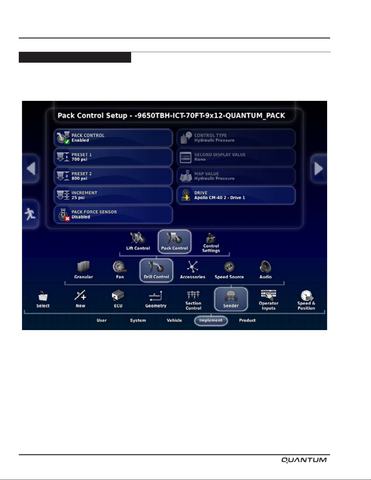
Hydraulic Pressure Control Setup
In the set-up Menu go to: Implement - Seeder - Drill Control - Pack Control
Set Preset1: 700PSI (use settings based on eld soil types)
Increment psi: 25
Pack Force Sensor: Disabled
Drive: Apollo CM-40 2- Drive 1
2 Tank units – Apollo CM-40 1 – Drive 1
3 Tank Units – Apollo CM-40 1 – Drive 1
If equipped with Liquid Sectional Control Pack Control to - Apollo CM-40 2 – Drive 1
5-18 January 2019
Page 49
Controller Options - Continued
Topcon - X35 Apollo - Continued
Hydraulic Pressure Control Setup - Continued
Operation
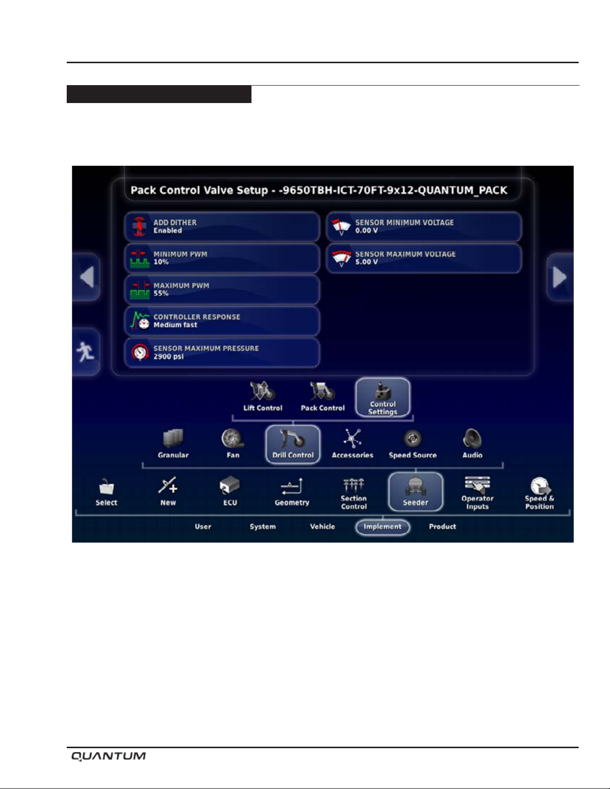
In the set-up Menu go to: Implement - Seeder - Drill Control - Control Settings
Dither Enabled
Min PWM: 10%
Max PWM: 55%
Controller Response: Medium Fast
Sensor Max Pressure: 2900psi
Sensor Minimum Voltage: 0.00V
Sensor Maximum Voltage: 5.00V
January 2019 5-19
Page 50
Operation
Controller Options - Continued
Topcon - X35 Apollo - Continued
Hydraulic Pressure Control Setup - Continued
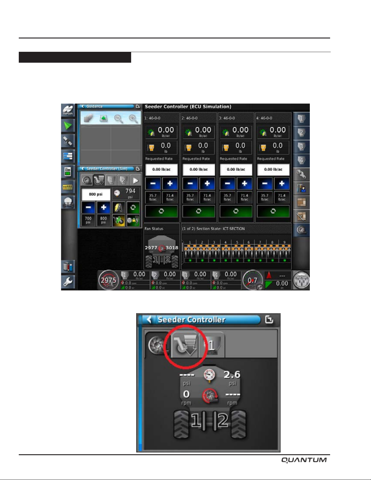
1.Return to the Seeder Home screen.
2. Press the Pack Control tab.
5-20 January 2019
Page 51
Controller Options - Continued
Topcon - X35 Apollo - Continued
Hydraulic Pressure Control Setup - Continued
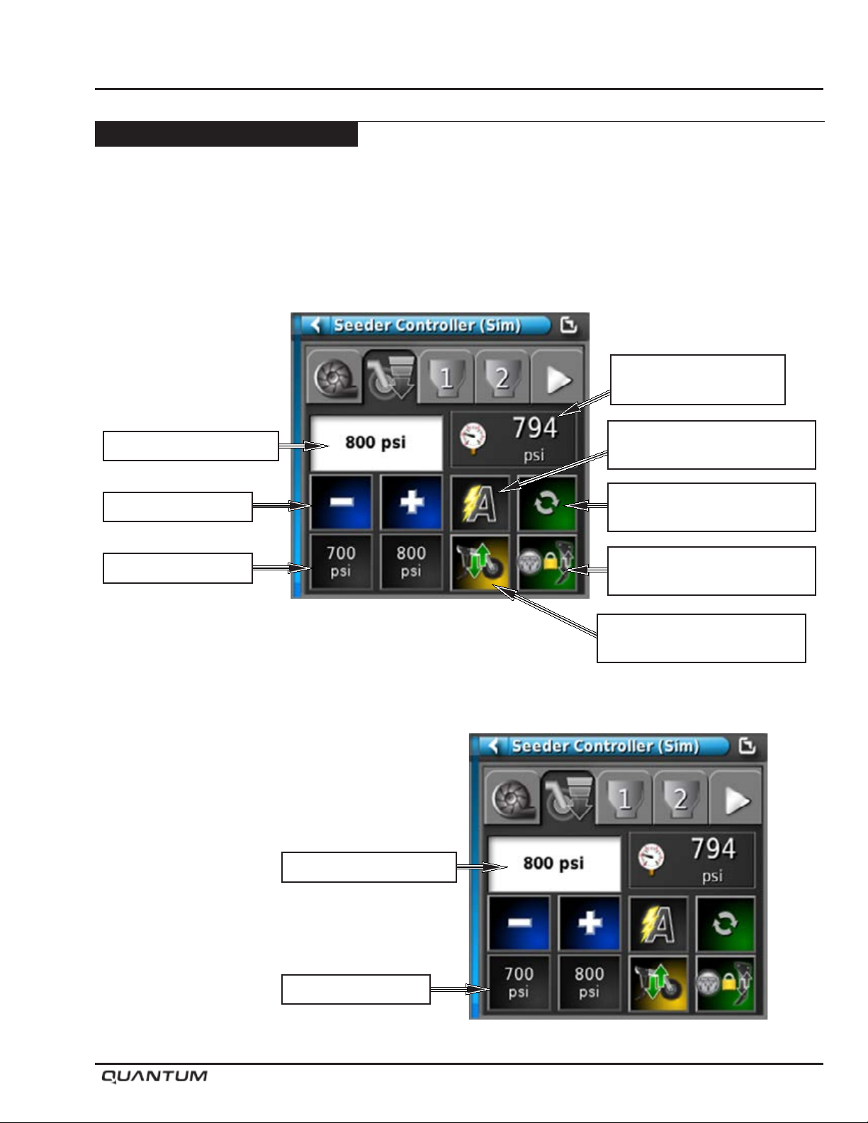
3. Pack Control Window
Drill Track Control - When Master Switch is activated
Lift / Lower will be automatically engaged.
Operation
Current
Hydraulic Pressure
Target - Pressure
Increase / Decrease
Preset 1 - 2
4. Set the target Pack force by pressing the desired
preset icon. The Target Pack Force will now be
displayed in the window..
AUTO MODE / Manual Mode
(Set to Auto)
FLOAT MODE - Turns
Pack Control ON / OFF
Drill Track Control
(Auto Lift)
Lift Control (Up / Down)
Over Ride
Target - Pressure
Preset 1 - 2
January 2019 5-21
Page 52
Operation
Controller Options - Continued
Topcon - X35 Apollo - Continued
Hydraulic Pressure Control Setup - Continued
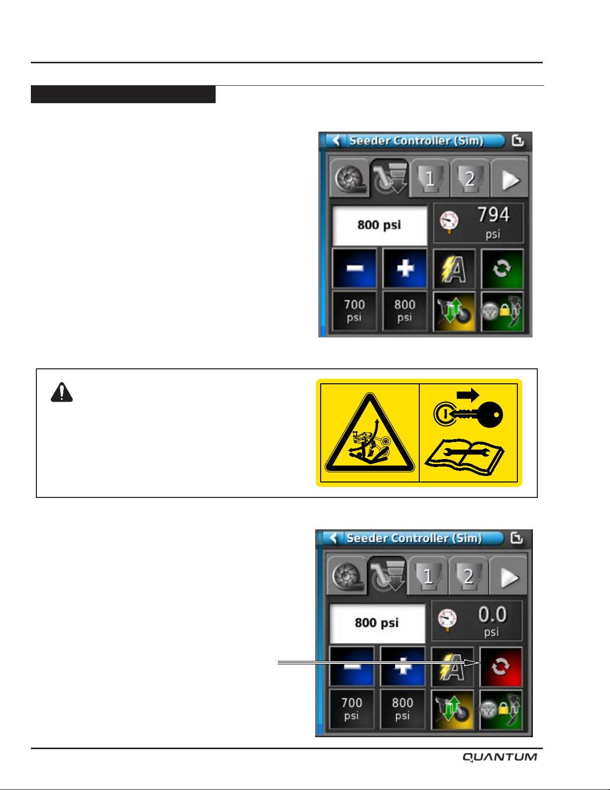
6. Testing Operation - With the tractor Hydraulics ON,
the openers should be in the UP position. When
Master Switch is engaged the openers will be lower
into the working position automatically.
Warning
Openers drop with full down force when
powering up or rebooting the X35 with
hydraulics engaged.
7. Special Operation - ON/OFF button when toggled
to OFF, allows the openers to Float over terrain in
the downward working position with no pressure
applied. This function is useful when travelling over
wash outs or in muddy conditions when the unit is
on the verge of becoming stuck.
S65155
5-22 January 2019
Page 53
Controller Options - Continued
Topcon - X35 Apollo - Continued
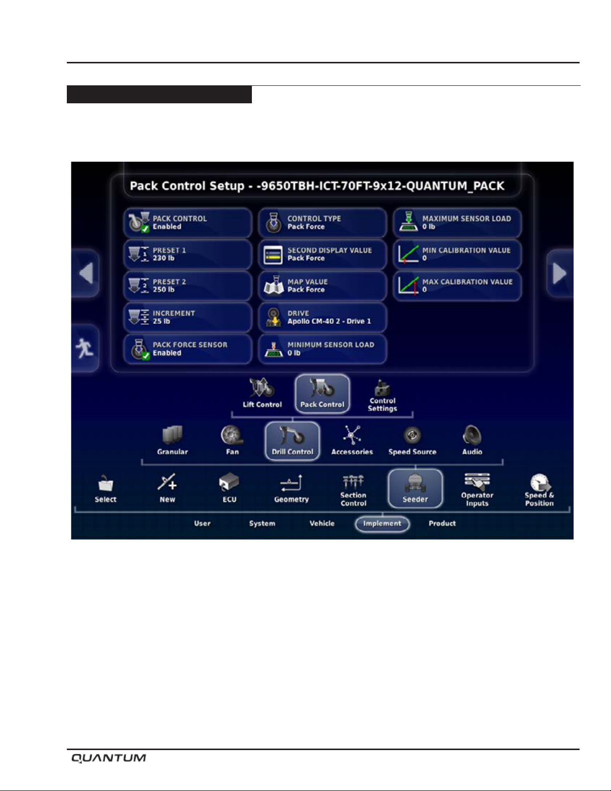
Pack Control Setup
Operation
In the set-up Menu go to: Implement - Seeder - Drill Control - Pack Control
Set Preset1: 230 lb (use settings based on eld soil types)
Increment psi: 25
Pack Force Sensor: Disabled
Drive:
2 Tank units - Apollo CM-40 1 - Drive 1
3 Tank Units - Apollo CM-40 1 - Drive 1
4 Tank Units - Apollo CM-40 2 - Drive 1
If equipped with Liquid Sectional Control set Pack Control to - Apollo CM-40 2 - Drive 2
January 2019 5-23
Page 54
Operation
Controller Options - Continued
Topcon - X35 Apollo - Continued
Pack Control Setup - Continued
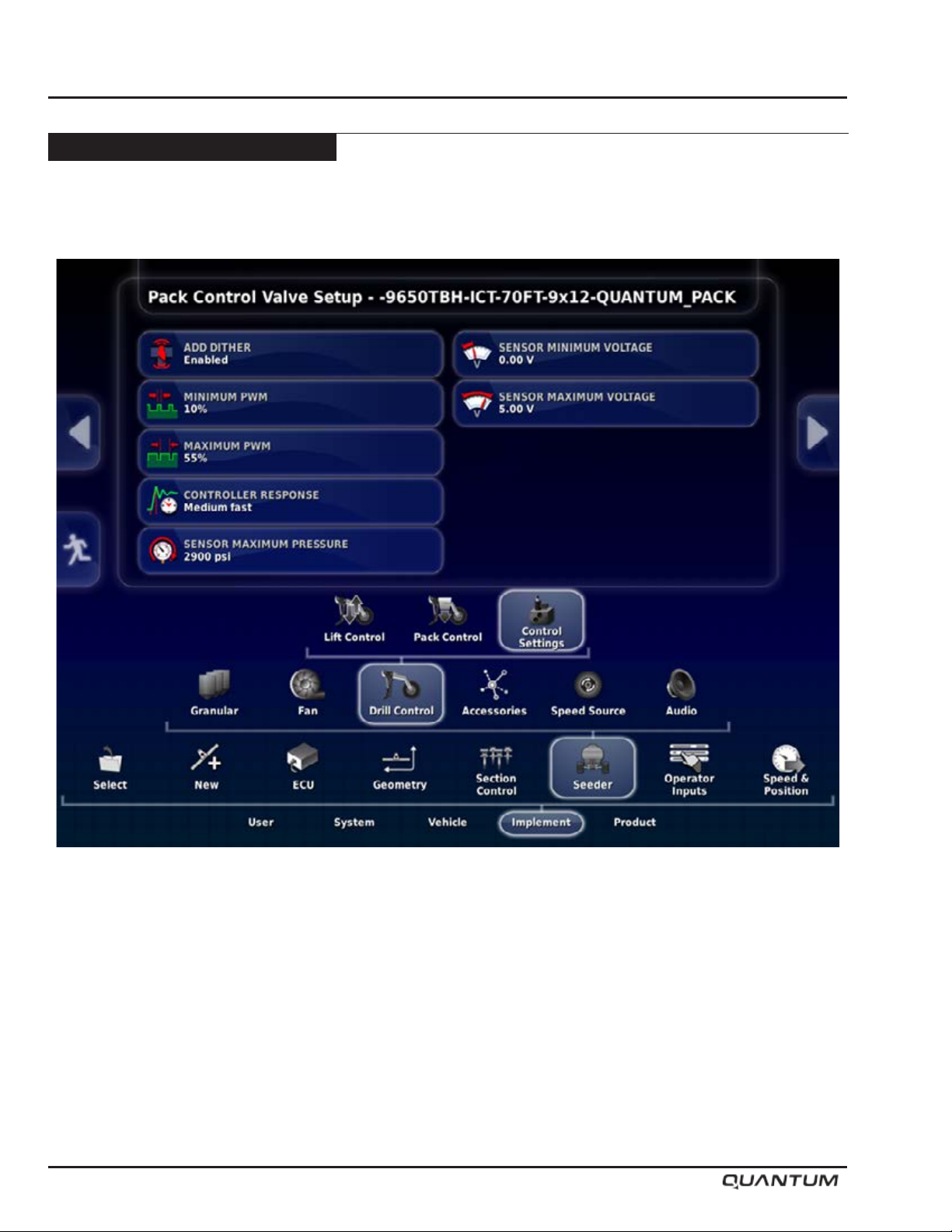
In the set-up Menu go to: Implement - Seeder - Drill Control - Control Settings
Dither Enabled
Min PWM: 10%
Max PWM: 55%
Controller Response: Medium Slow . . . if controler does not react quick enough set to Medium Fast.
Sensor Max Pressure: 2900psi
Sensor Minimum Voltage: 0.00V
Sensor Maximum Voltage: 5.00V
5-24 January 2019
Page 55
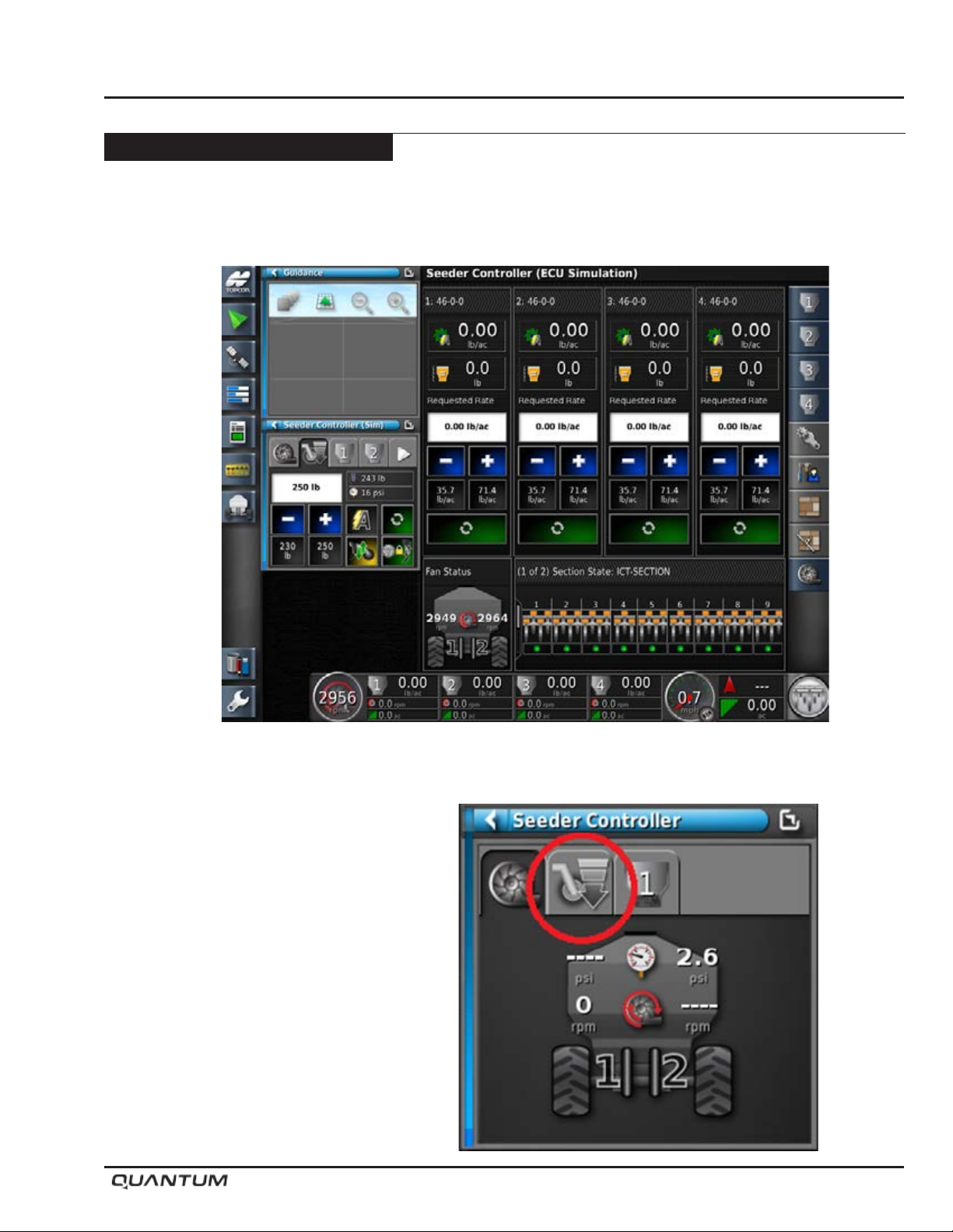
Controller Options - Continued
Topcon - X35 Apollo - Continued
Pack Control Setup - Continued
1. Return to the Seeder Home screen
Operation
2. Press the Pack Control tab.
January 2019 5-25
Page 56
Operation
Controller Options - Continued
Topcon - X35 Apollo - Continued
Pack Control Setup - Continued
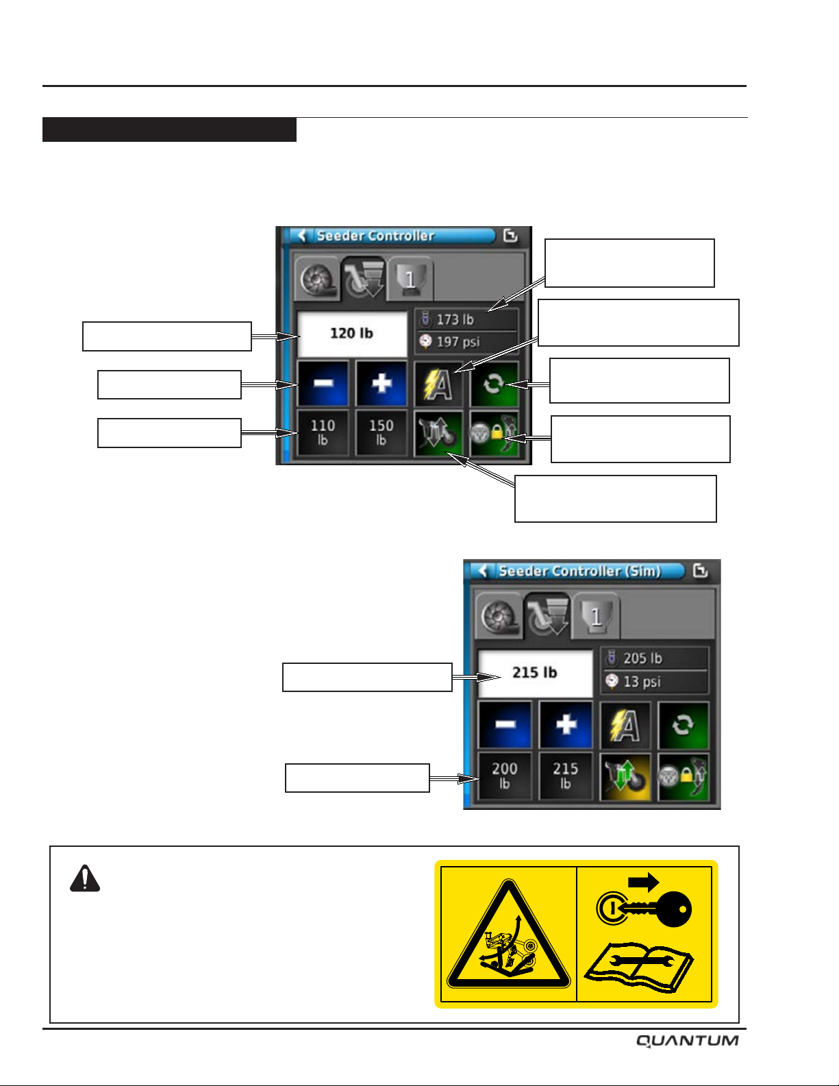
3. Pack Control Window
Drill Track Control - When Master
Switch is activated, Lift/Lower will
be automatically engaged.
Target - Pack Force Rate
Current Pack Force /
Hydraulic Pressure
AUTO MODE / Manual Mode
(Set to Auto)
Increase/Decrease
Preset 1 - 2
4. Set the target Pack force by pressing the desired
preset icon. The Target Pack Force will now be
displayed in the window.
Target - Pack Force Rate
FLOAT MODE - Turns
Pack Control ON / OFF
Drill Track Control
(Auto Lift)
Lift Control (Up / Down)
Over Ride
Preset 1 - 2
Warning
Openers drop with full down force when
powering up or rebooting the X35 with
hydraulics engaged.
5-26 January 2019
S65155
Page 57
Controller Options - Continued
Topcon - X35 Apollo - Continued
Pack Control Setup - Continued
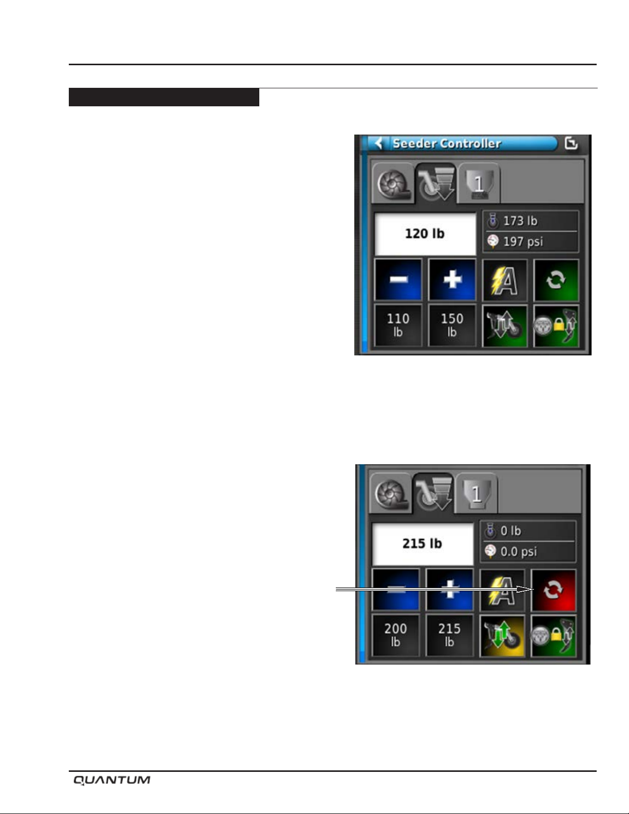
6. Testing Operation - With the tractor Hydraulics ON,
the openers should be in the UP position. When
Master Switch is engaged the openers will be lower
into the working position automatically.
Note: Operator will have to be aware of changing
soil conditions across drill as Load Cell
maybe in softer or harder soil than the rest
of the drill.
Operation
7. Special Operation - ON/OFF button when toggled
to OFF, allows the openers to Float over terrain in the
downward working position with no pressure applied.
This function is useful when travelling over a wash
outs or in muddy conditions when the unit is on the
verge of becoming stuck.
January 2019 5-27
Page 58
Operation
Controller Options - Continued
Topcon - X35 Apollo - Continued
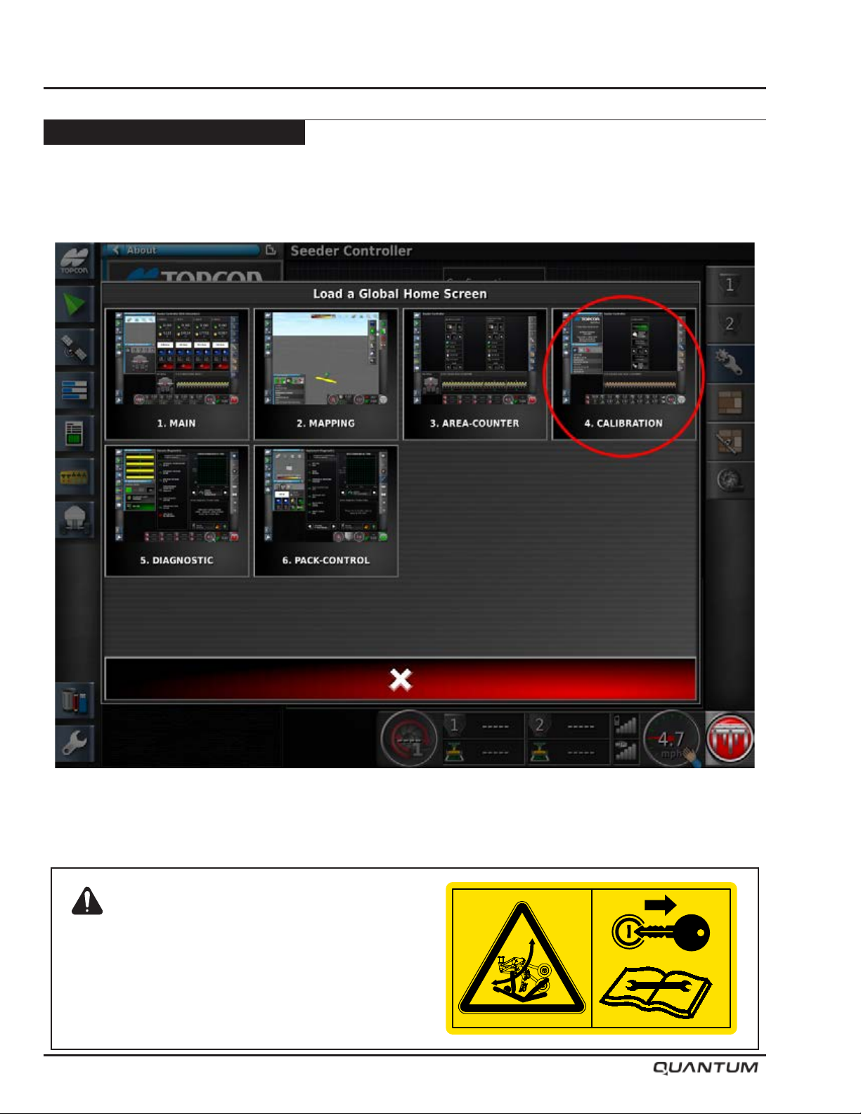
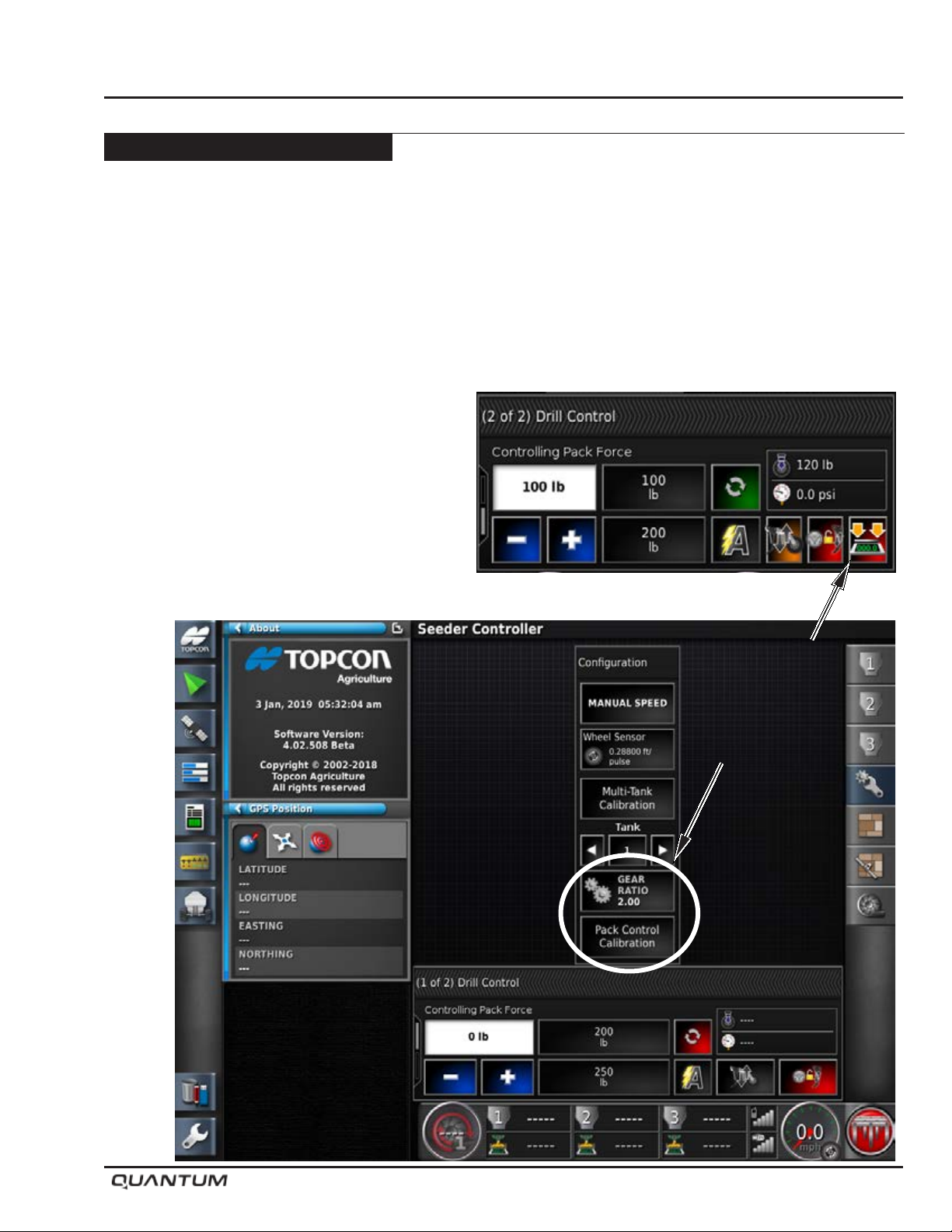
Pack Control Calibration
1. Go to Calibration screen
Warning
Openers drop with full down force when
powering up or rebooting the controller with
hydraulics engaged.
5-28 January 2019
S65155
Page 59
Controller Options - Continued
Topcon - X35 Apollo - Continued
Pack Control Calibration - Continued
2. Press Pack Control Calibration to reveal Drill Control.
3. Press Calibration Wizard ICON on bottom Right.
Note: Depending on the firmware versions it can
be either in the menu or calibration page.
Operation
January 2019 5-29
Page 60
Operation
Controller Options - Continued
Topcon - X35 Apollo - Continued
Pack Control Calibration - Continued
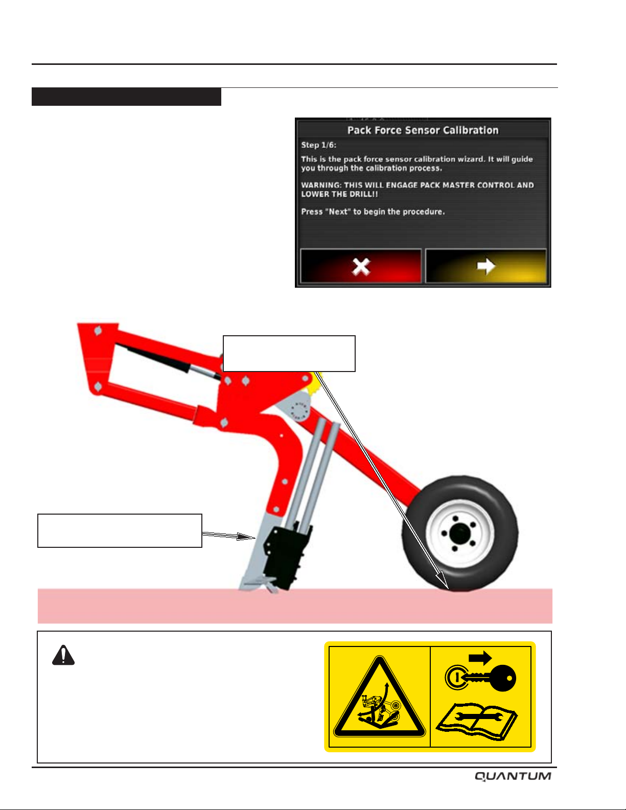
4. Calibration wizard- Proceed with Yellow arrow.
Place Pan Scale under
Packer Wheel
5. Place Pan Scale under Packer Wheel, (Remove the Opener Knife / Boot Shank assembly)
Remove the Opener
Knife / Boot Shank assembly
Warning
Openers drop with full down force when
powering up or rebooting the controller with
hydraulics engaged.
5-30 January 2019
S65155
Page 61
Controller Options - Continued
Topcon - X35 Apollo - Continued
Pack Control Calibration - Continued
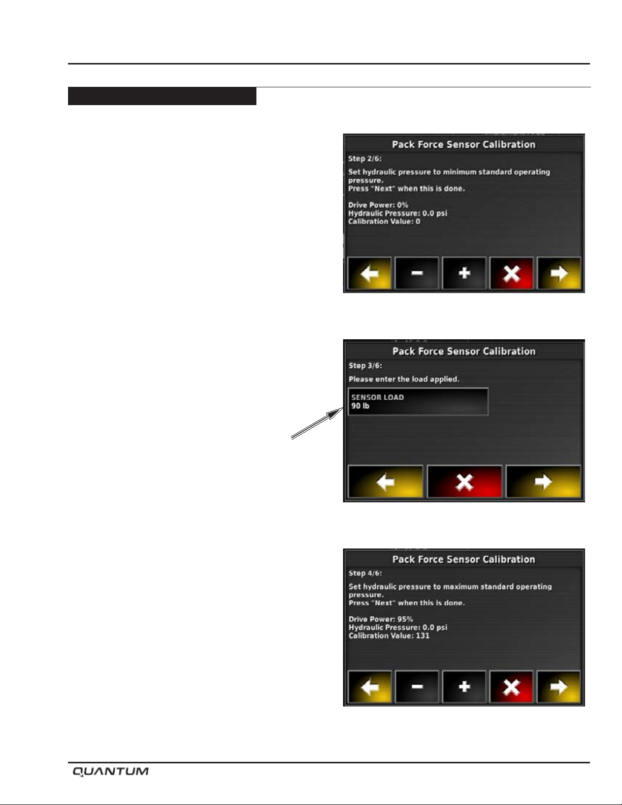
6. Engage hydraulics and run the PWM up using the
(+) icon until the opener pressure is running at the
minimum value required to keep the opener in the
ground to ensure we have an accurate reading on
the scale.
Drive power up to the minimum amount of PWM to keep
the opener down, and locked into the working position.
As an example 10% PWM
Press the Yellow Forward ARROW
Operation
7. Enter the weight displayed on the Pan scale, under
the opener tire.
Proceed with the Yellow arrow (Note: Do not use the
numbers used in this guide, enter the weight from
the Pan Scale).
8. At step 4 do not run it to max PWM, just run it to a
hydraulic pressure value which would be considered
a standard high pressure operating value.
60% PWM
Proceed with the Yellow forward arrow.
January 2019 5-31
Page 62
Operation
Controller Options - Continued
Topcon - X35 Apollo - Continued
Pack Control Calibration - Continued
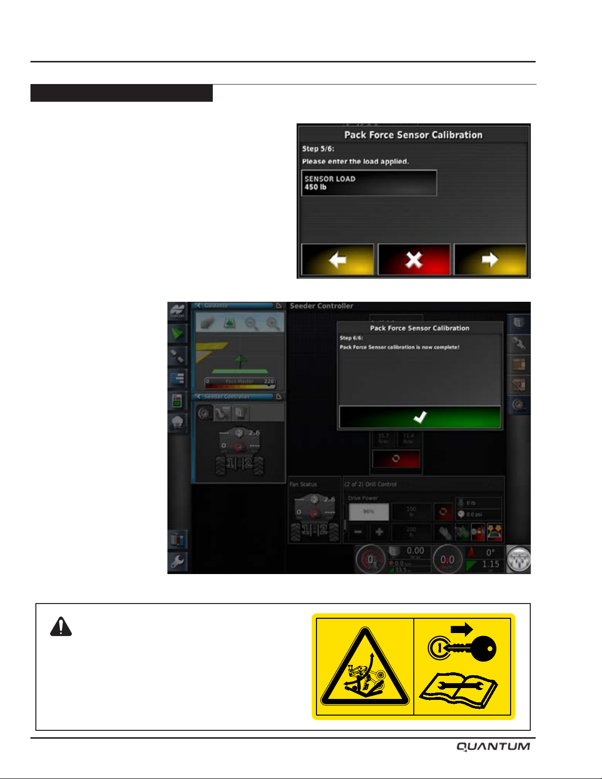
9. Enter the weight displayed on the Pan scale.
Note: Once the correct weight read off the scale at
both points is entered, the resting weight of
the opener assembly is included in the pack
force weight displayed.
Warning
Openers drop with full down force when
powering up or rebooting the controller with
hydraulics engaged.
5-32 January 2019
S65155
Page 63
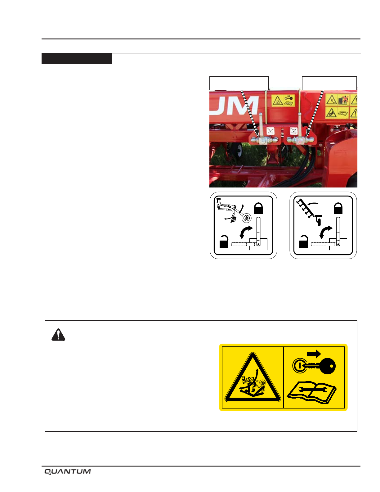
Depth Adjustment
To adjust seed depth:
• Lift openers to raised position.
• Shut tractor off and remove key.
• Ensure tractor park brake is engaged before
proceeding.
• Place “Openers” ball valve into locked position to
prevent accidental oil ow to openers.
Operation
Openers Valve Wing Valve
Warning: Crushing Hazard
To prevent serious injury or death:
• Stand Clear - openers move rapidly under hydraulic
pressure.
• Before servicing hydraulics - Lower openers to ground
and relieve pressure from hydraulic system.
• Shut tractor off and remove key before servicing or
adjusting depth.
• Place “Openers” valve in locked position before adjusting
depth or transporting.
S65157 S65156
S65155
January 2019 5-33
Page 64
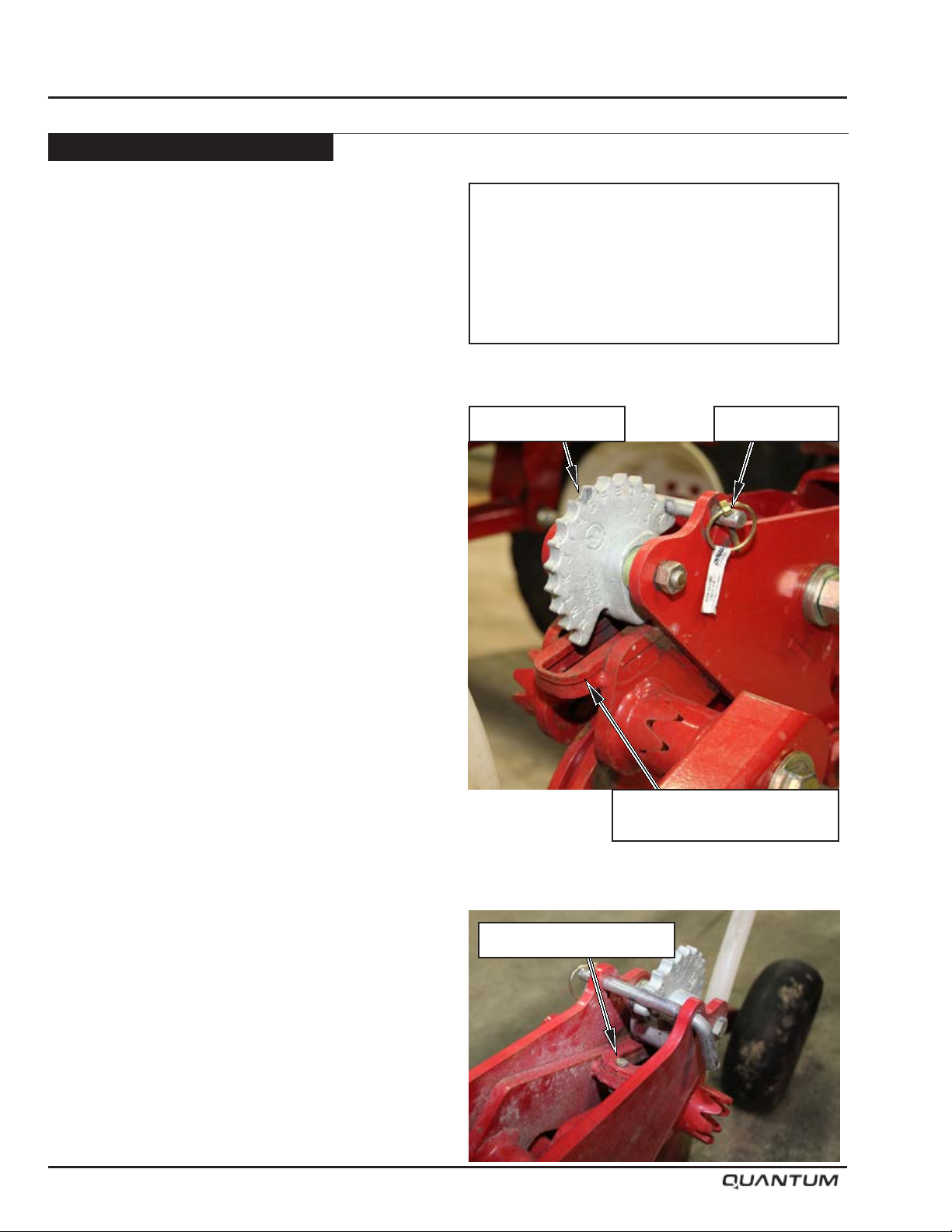
Operation
Depth Adjustment - Continued
• Remove lynch pin from 1/2” diameter depth pin.
• Remove depth pin.
• Rotate depth cam to desired lettered setting (“A” is
the shallowest postition). Each increment changes
the depth a 1/4” (6.4 mm).
• Reinstall 1/2” pin and lynch pin noting letter position
before adjusting other openers.
Note: For ease of adjustment, adjust a few openers
across the drill to conrm desired seeding
depth before adjusting the remaining
openers.
• Move the “Openers” ball valve to the unlocked
position before using drill.
Depth Range Interval Change
• A shim in the normal operating position (produces
depth range results similar to the C2).
• Removing the shim will make each position on the
depth cam 1” (25.4 mm) deeper.
i.e. if the seeding depth is at 1” (25.4 mm) and the
shim is removed the seeding depth would now be
at 2” (50.8 mm) roughly.
• The depth cam remains the same i.e. going from
A to B will change the depth by 1/4” (6.4 mm).
Important
Pneumatic Tires Only.
Keep opener tires air pressure at the listed
specifications to achieve and maintain proper
seed depth.
Adjustment Cam Lynch Pin
5-34 January 2019
Shim Location
Normal Operating Position
Shim Retaining Bolt
Page 65
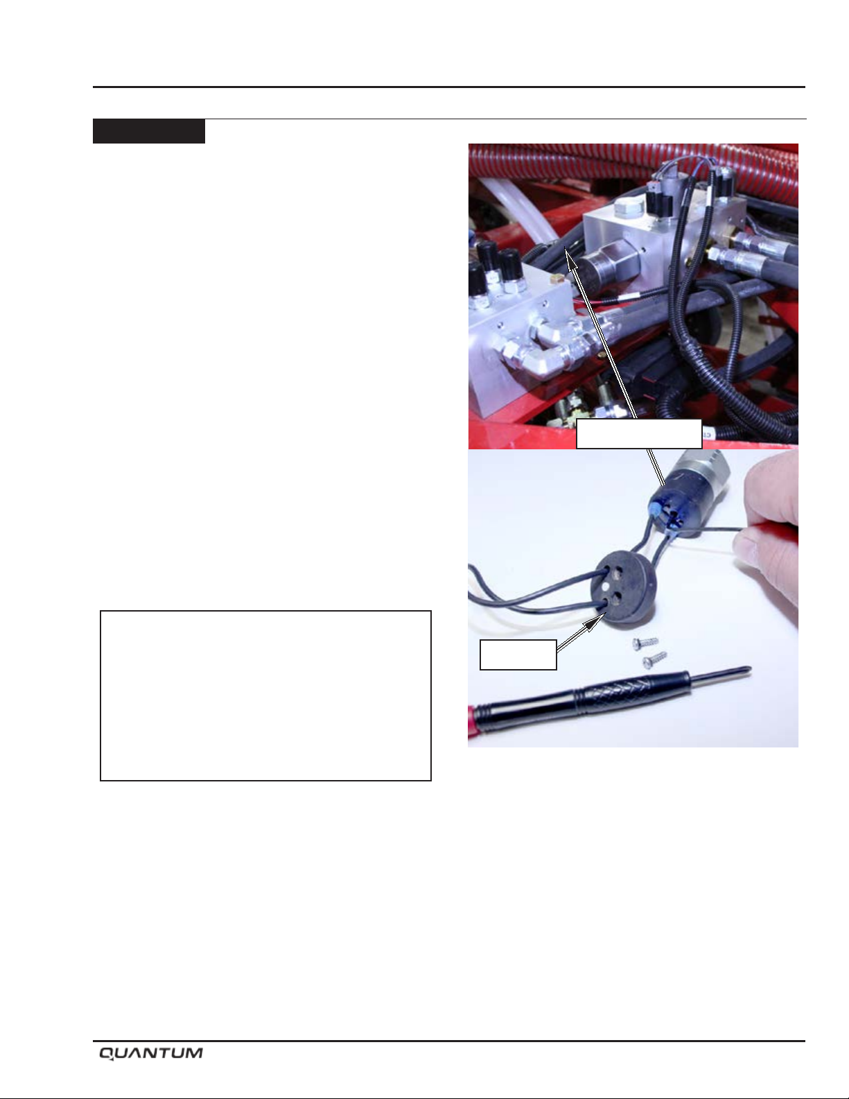
Work Switch
(Optional equipment)
The pressure work switch activates the Air Cart Metering
system by the hydraulic pressure on the opener lift side.
When the openers are raised the switch opens at a
pre-set pressure turning off the Air Cart metering and
when lowered the switch closes at the pre-set pressure
to turn on the metering.
The pre-set Factory set point meets most operators’
preference. If the turn ON and OFF time needs to be
adjusted follow the procedure below:
• Remove cover from back of switch.
• Insert a 3/32” allen wrench into the adjustment screw
opening. Turn the screw clockwise to increase the
set point or counter clockwise to decrease.
- Increasing set point will cause the metering system
to turn ON quicker. This will also cause the
metering system to turn OFF later.
- Decreasing set point will cause the metering
system to turn ON later. This will also cause the
metering system to turn OFF quicker.
Operation
Work Switch
Important
Ensure metering clutch is turned OFF when
moving unit to prevent damage to metering
wheels in the event pressure switch is in ON
position.
January 2019 5-35
Cover
Adjustment Screw
Page 66
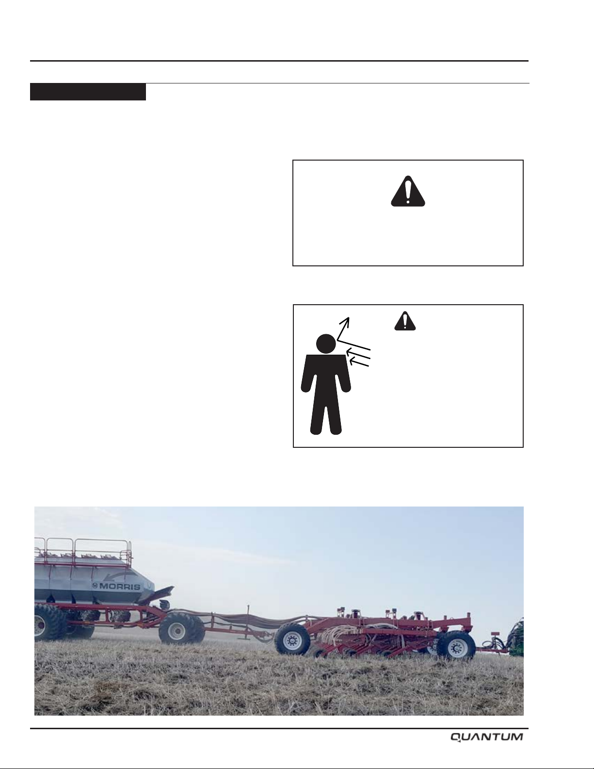
Operation
General Guidelines
The results obtained from the Morris QUANTUM Drill
are directly related to the depth uniformity of the unit.
Worn points, uneven tire pressures, and bent shanks
must be avoided to obtain optimum eld results.
• Operating depth should be uniform at all opener
locations, when spot checking the implement in the
eld.
• Check openers running in tractor or air cart tracks
and adjust depth accordingly.
• Repair or replace bent shanks. Bent shanks cause
openers to work at uneven depths and can cause
unnecessary ridging. See Maintenance Section.
• Keep tire pressure at the listed specications to
maintain proper level. See Maintenance Section.
• Have Air Drill moving forward before lowering into
ground to avoid plugging openers.
• Avoid sharp turns. Turns sharp enough to cause
the inside openers of the air drill to reverse direction
are not recommended. This may cause the seed
openers to plug.
TAKE SAFETY SERIOUSLY.
Do Not Take Needless Chances!
Caution
Care should be taken when
working near the air cart
while the fan is running.
Product blowing out of
the system could cause
personal injury.
5-36 January 2019
Page 67
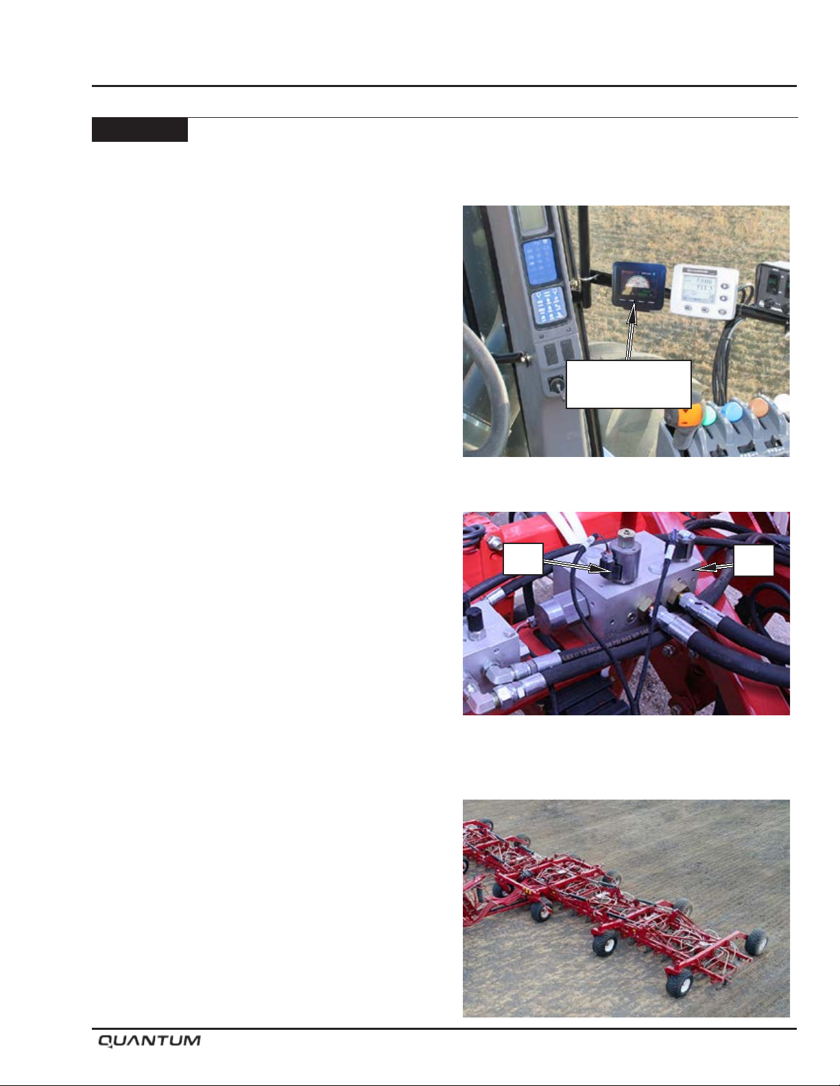
Quick Tips
Note: Read the Operator’s Manual for detailed
operating and adjustment instructions.
Shank Trip Force
Shank trip force (lbs) is calculated by dividing the display
pressure by 1.5 (ex. 750 psi display pressure = 500 lbs
shank trip force). Shank trip out pressure is generally
set at the minimum pressure that keeps the shanks
solid in the vertical position and prevents them from
repeatedly “tripping out”, while still providing adequate
packing. Maximum recommended shank trip out
pressure is 1200 psi.
Packing Force
Packing force is proportional to shank trip out force
and is roughly 1/3 of the shank trip force (ex. 500 lbs
shank trip force would give approximately 167 lbs of
packing force).
Operation
JEM Display
Pressure Gauge
Hydraulic System
The Quantum Air Drill uses an active hydraulic system
meaning that approximately 3-4 GPM will be consumed
by the system during operation. A reducing/relieving
valve (S2) sets the pressure value and is controlled
from the cab. Operating pressure range is normally
anywhere from 500 to 1500 psi depending on soil
conditions, opener selection and ground speed. Opener
pressure can be reduced on the go for soft spots or tilled
areas in the eld or increased for hard packed areas.
Float position (equal pressure on both sides of opener
cylinder) is also possible using the Topcon system and
can be effective at walking the drill through low spots.
Lifting and Lowering the Openers
Openers will travel all the way up or all the way to
working position based on the controller selection; there
is no middle operating position. Ensure the openers are
fully lifted with the transport ball valve locked and the
tractor hydraulics off for road transport.
S2
S1
January 2019 5-37
Page 68
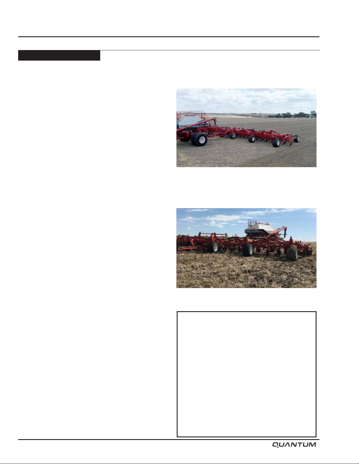
Operation
Quick Tips - Continued
Setting the Seed Depth
Seed depth is measured from the packed soil surface to
the seed. Set the seed depth on the drill by setting a few
openers across the drill to different depths and seeding
a test patch. Always seed the test patch at the same
ground speed and opener pressure that you intend to
maintain during regular seeding conditions. Then check
the seed depth of these openers, pick the depth setting
that you prefer, and set all openers to the desired letter
setting on the depth adjustment cam. The openers
perform best while seeding from 1/2” (13mm) to 1-1/2”
(38 mm) seed depth, but each customer is responsible
for choosing their own depth setting according to their
preferences and experience. Each adjustment notch
on the adjustment cam is 1/4” (6.4 mm) adjustment.
Shallow depth settings can be consistently maintained
with the QUANTUM Air Drill system.
Note: Be sure to check tractor and/or air cart tracks
to see if the added soil compaction has
affected the seed depth; the independent
openers can be adjusted separately to
compensate for wheel tracks.
Seeding Conditions
The QUANTUM Air Drill is meant to be used as a
minimum to no-till seeding system and care should
be taken when attempting to seed into loose or preworked soil conditions. Shallow seeding depth, reducing
operating speed and operating pressure may help
reduce soil throw and ridging in soft conditions.
Note: Soil throw onto adjacent seed rows also
occurs on conventional air drills with gang
style packers, but is less visible because the
gang packers pack all rows simultaneously
at the back of the drill.
Straw Management
Successful seeding starts at harvest. The height of the
straw should not exceed the row spacing of the seeding
unit. The combine should chop the straw and spread the
straw and chaff evenly across the entire swath width. A
heavy harrow may also be required to spread and break
down the straw after the eld has been harvested. If
the straw height does exceed the row spacing a mower
should be used to shorten the straw length.
IMPORTANT
The Paired Row Opener with the NH3 adapter
is intended to allow the operator the flexibility to
switch between granular fertilizer and NH3 without
having to change openers. The opener is not
intended to apply granular fertilizer and NH3 in
the same operation. Excessive gassing off of the
NH3 will occur in such an operation. Producers
are still able to place starter fertilizer with the seed.
Morris Industries shall have no obligation or
liability of any kind on account of the end-user
incorrectly using this opener.
5-38 January 2019
Page 69
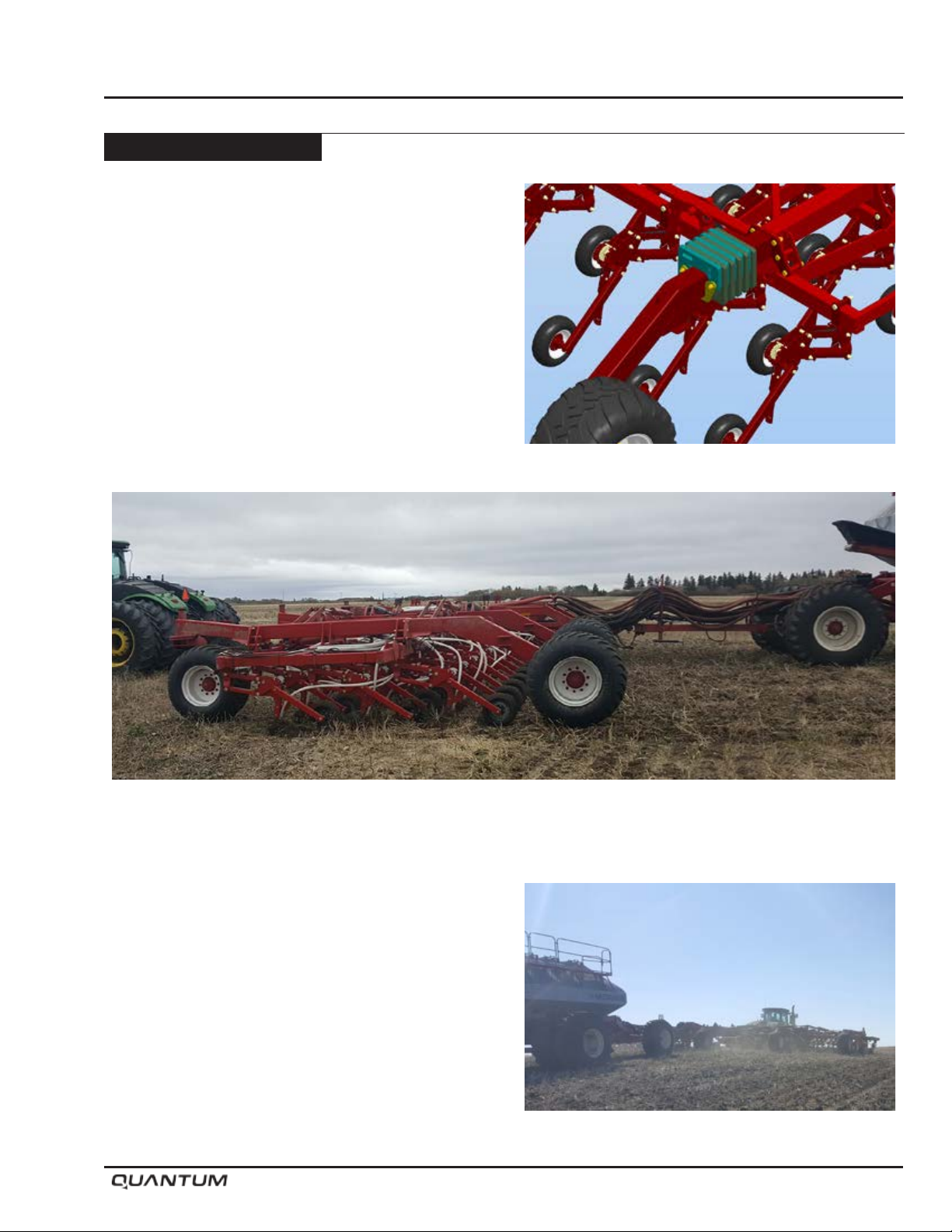
Quick Tips - Continued
Air Drill Frame
The QUANTUM Air Drill frame is a simple slab frame
system, designed to let the parallel link openers do
the work of depth control and leveling during seeding.
No leveling of the frame is required. During normal
operation of the drill there will be very little weight on the
rear tires of the frame. The rear tires may even leave
the ground while traveling through sharp gullies; this is
normal, and it will not affect the seed depth control of
the openers. If the tires are lifted in the air consistently,
optional weight kits can be applied to the depth beams
near the rear axles.
Operation
Weight Kit
Normal Frame Angle
Trouble Shooting Guide
*Note: Remove all pressure from hydraulic systems
before attempting any service work on
hydraulic components.
Hydraulic system must be bled after it has been
serviced (if any portion of the system has been opened
to atmosphere) and also on initial start-up or if spongy
or irregular trip operation is occurring. See “Bleeding
Hydraulic System” in Maintenance Section.
January 2019 5-39
Page 70
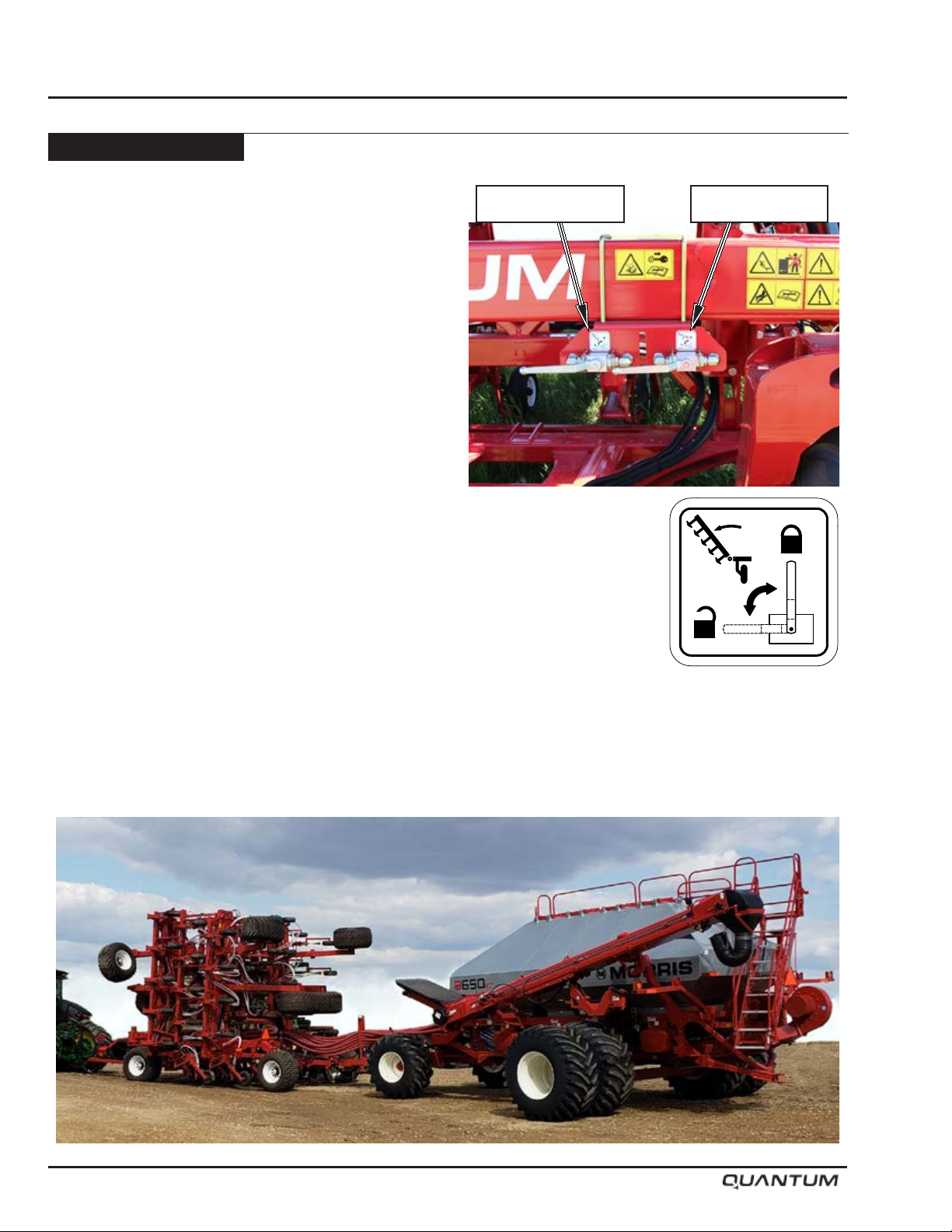
Operation
Wing Lift Hydraulics
The wing lift hydraulic system is controlled by a
parallel hydraulic system. A pressure compensated
Flow Control Valve is used to control the ow of oil to
the cylinders allowing both wings to fold and unfold
simultaneously. A hydraulic circuit Shut Off valve is used
to lock the hydraulic circuit and prevent any leak back,
this ensures the wings remain in transport.
The Flow Control Valve is located on the main frame
and there are no adjustments associated with the valve.
The Shut Off valve is located on the front wing lift truss
for easy access.
To unfold the Air Drill, the oil ows to the Flow Control
Valve, from there to the butt end of all the wing lift
cylinders extending the shafts and lowering the wings.
All cylinders must be fully extended to ensure correct
operation of the machine.
Placing the unit into transport is the reverse of unfolding
the unit. Oil is fed to the shaft end of the cylinders
retracting the cylinders and lifting the wings into
transport position.
Openers Valve Wing Valve
Note: When raising or lowering wings, do so in one
continuous motion until fully up or down. Do
not stop ow part way allowing wings to fold
on their own. This may disrupt the sequence
of operation.
S65156
5-40 January 2019
Page 71
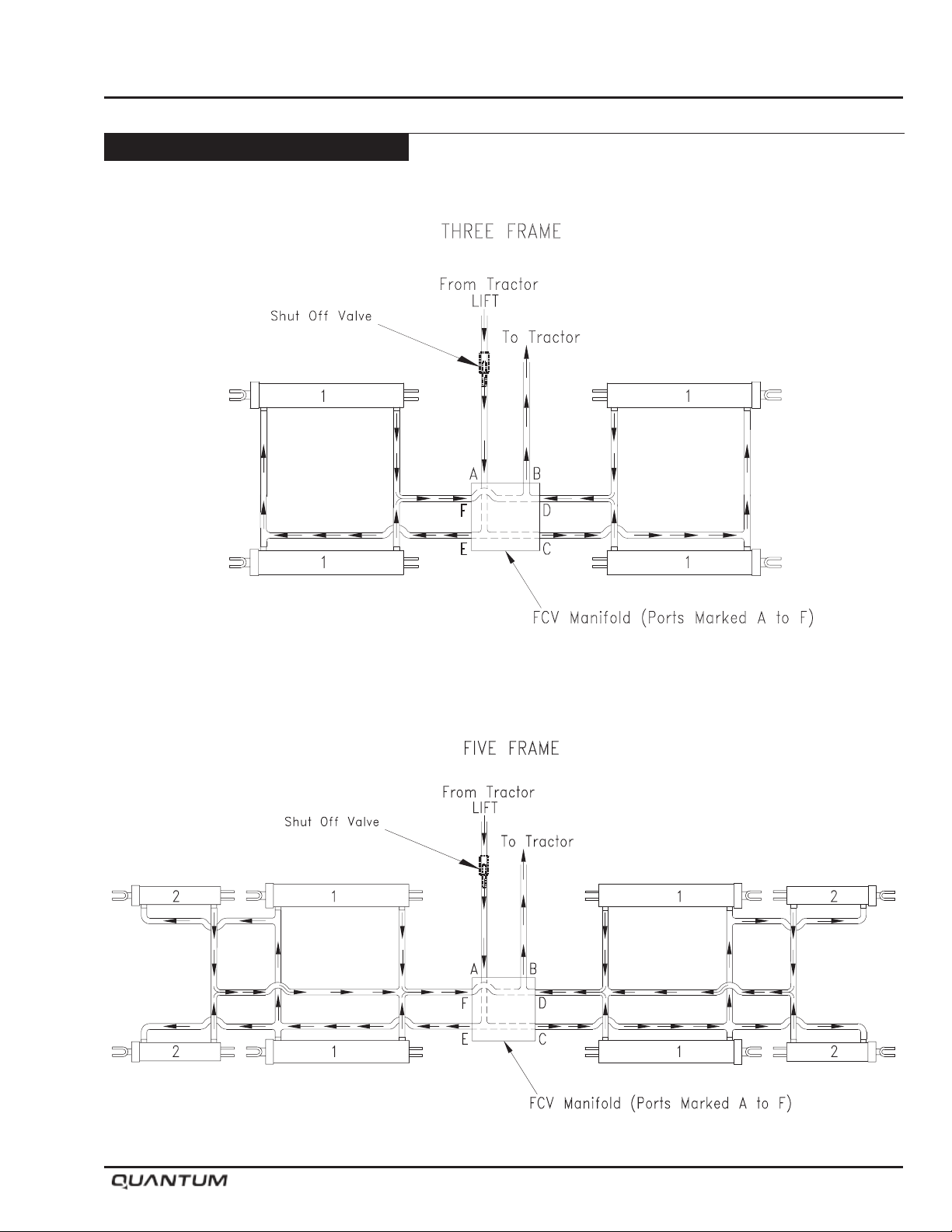
Wing Lift Hydraulics - Continued
Three Frame Models
Operation
Five Frame Models
January 2019 5-41
Page 72

Operation
Opener Hydraulics
The QUANTUM uses an active hydraulic control system.
This means the tractor’s hydraulic circuit to the QUANTUM openers are permanently engaged into the working
position through manifold block (S64940) which controls the Lift-Lower and packing pressure functions via a controller
and an in cab display.
The controller and display provides the user the ability to adjust the opener downforce packing pressure on the go
from inside the cab while applying product.
The following is the oil ow for both operating types and can be used for problem diagnosis.
To lower
• Pressing Opener “DOWN” button on the controller will lower the openers all the way down and lock them into
working position by shifting solenoid valve “S1” which actuates pilot directional valve “PD”; “PD” valve in the diagram
will be at its default position of ow straight through.
To raise
• Pressing Opener “UP” button on the controller will lift the openers fully up by shifting solenoid valve “S1” which
actuates pilot directional valve “PD”; “PD” valve in the diagram will be shifted to cross the ow over (arrows crossed
symbol).
Pressure Setting:
• Pressure can be adjusted on the go from the tractor cab using the display.
• Pressing the Pressure “INC” button on the display will increase the pressure by shifting proportional reducing/
relieving valve S2 in the block; each press of the arrow will lift the pressure value by approximately 25 psi (172
kPa).
• Pressing the Pressure “DEC” button on the display will decrease the pressure by shifting proportional reducing/
relieving valve S2 in the block; each press of the arrow will drop the pressure value by approximately 25 psi (172
kPa).
• The system will remember the last pressure setting that it operated at and revert to that at next start up.
Trouble Shooting
The opener valve (S1) has two states; ON (opener UP) and OFF (opener DOWN). When the opener valve is on/UP,
the output is set to 3000mA (default value). When the opener is off/DOWN, the output is set to 0mA. These signals
can be measure with a multi-meter directly at the valve connection. Just pull the plug out of the coil and measure the
amperage across the two pins of the wire harness connector. Pin 1 of the S1 wire harness connector is connected
to the controller output and pin 2 is connected to ground. Check these values without any hydraulic power.
The pressure reducing valve (S2) output is dependent on the state of the opener valve. If the opener is on/UP, the
output to the S2 valve is 1050mA, or roughly 87.5% of the max value of that valve (approximately 1750psi). When
the opener is off/DOWN, the output to the S2 valve is whatever value has been set by the user via the display. As it
is now, this value can be anywhere from 350mA to 1200mA.
S1 and S2 are both current-controlled PWM outputs. Make sure to measure amperage and not voltage.
Comm Icon: Cable is not connected correctly, Cable is not terminated correctly, incorrect rmware loaded / Board
Revision.
5-42 January 2019
Page 73
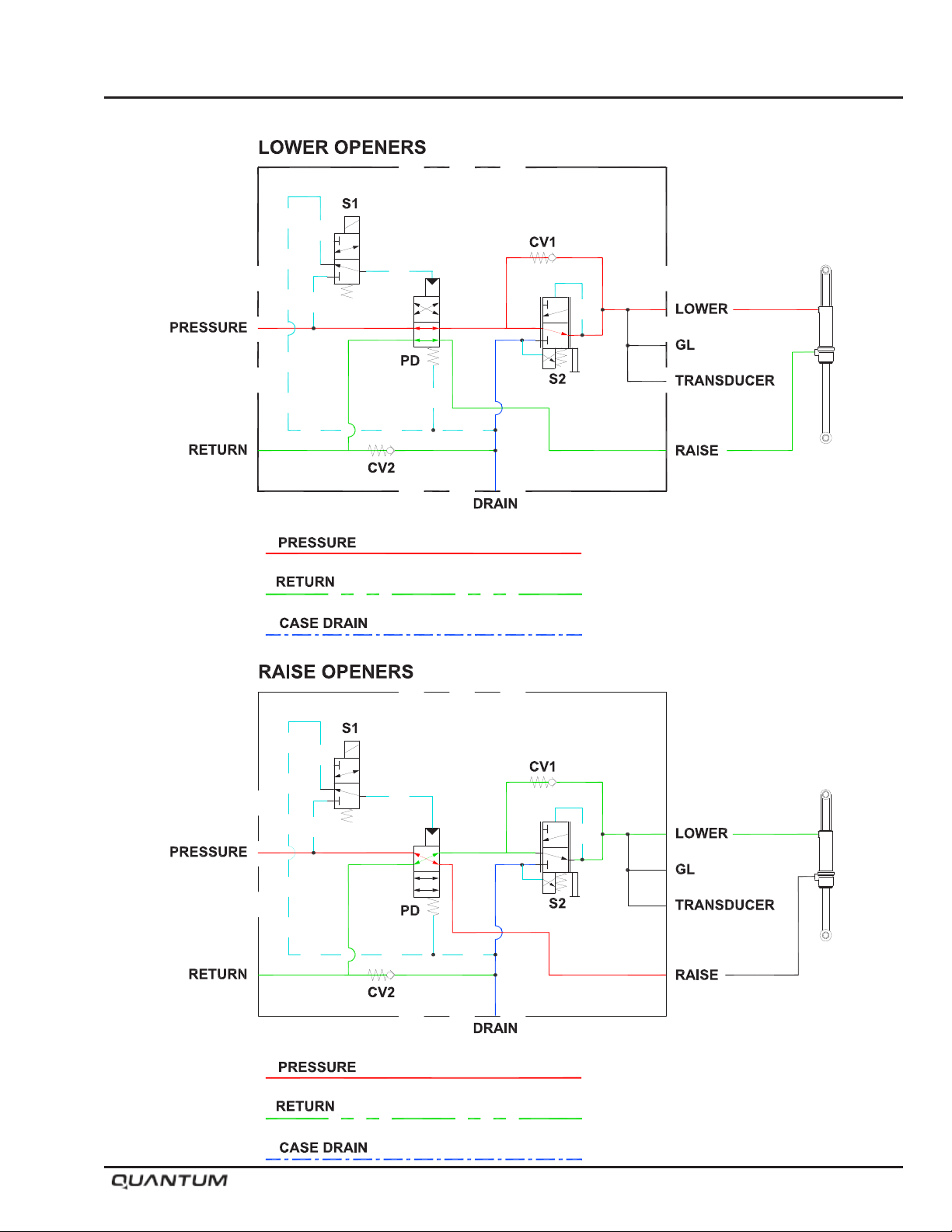
Operation
January 2019 5-43
Page 74

Operation
Notes
5-44 January 2019
Page 75

Section 6: Maintenance
Maintenance
Section 6:
Maintenance 6-1
Section Contents
General .............................................................................................................................6-4
Safety ...............................................................................................................................6-4
Tighten Bolts .....................................................................................................................6-5
Tires ..................................................................................................................................6-5
Lubrication ........................................................................................................................6-6
Opener Maintenance ........................................................................................................6-7
Bushing Replacement ................................................................................................6-7
Cylinder Replacement ................................................................................................6-7
Opener Body Assembly..............................................................................................6-8
Opener Assembly .....................................................................................................6-10
Shank Replacement .................................................................................................6-17
Bleeding Hydraulic System.......................................................................................6-18
Hydraulic System Trouble Shooting ..........................................................................6-19
Hydraulics .......................................................................................................................6-20
Wheel Bearings ..............................................................................................................6-21
Implement Hub .........................................................................................................6-21
Contour Opener Hub ................................................................................................6-22
January 2019 6-1
Page 76
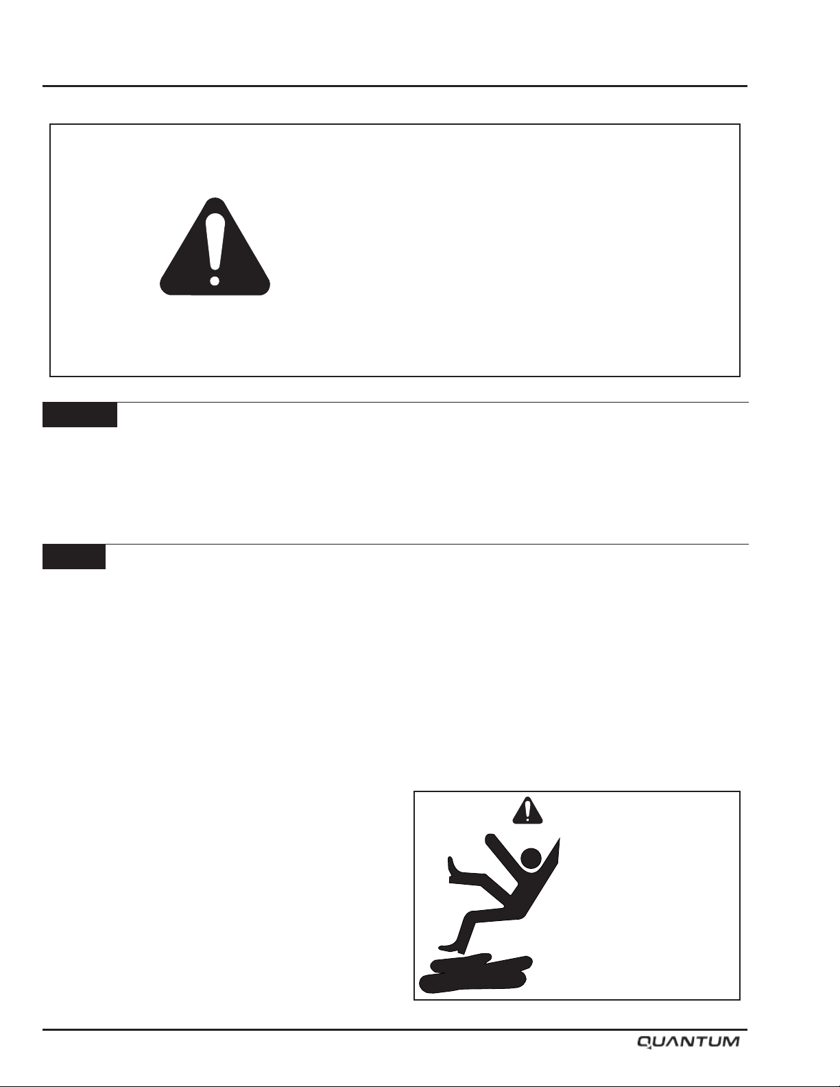
Maintenance
CAUTION
BE ALERT
General
This section deals with two goals, maximum life and
dependable operation. Adopt a regular maintenance
and lubrication program. Care and sufcient lubrication
is the best insurance against delays.
SAFETY FIRST
REFER TO SECTION 1 AND REVIEW ALL
SAFETY RECOMMENDATIONS.
Safety
• Always shut off the tractor and remove key before
dismounting.
• Guard against hydraulic high pressure leaks with
hand and face protection.
• Never work under the implement unless it is in the
down position or transport lock pins are in place
and secured with hair pins. Do not depend on the
hydraulic system to support the frame.
• Always wear safety goggles, breathing apparatus
and gloves when working on seeder filled with
chemical. Follow manufactures recommended safety
procedures when working with chemicals or treated
seeds.
• Do not feed left over treated seed to livestock, treated
seed is poisonous and may cause harm to persons
or livestock.
Caution
Keep service area clean
and dry. Wet or oily
floors are slippery.
6-2 January 2019
Page 77
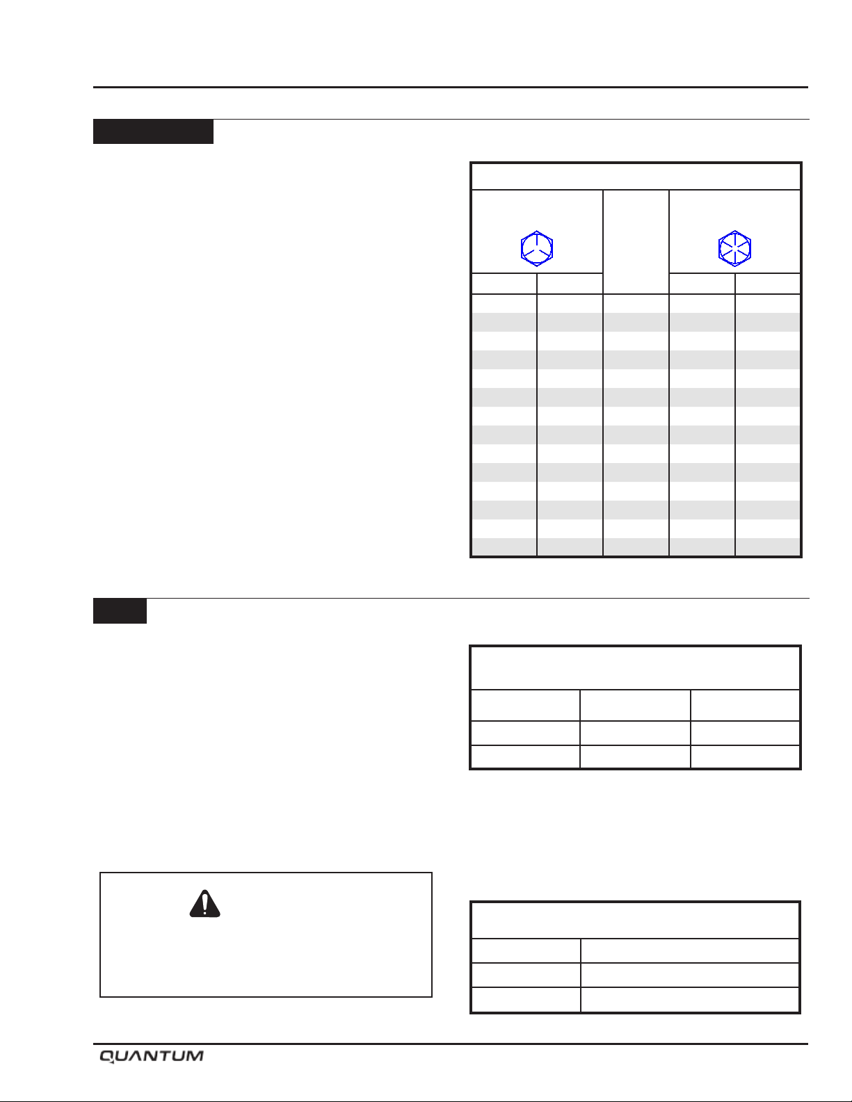
Tighten Bolts
• Before operating the machine.
• After the rst two hours of operation.
• Check tightness periodically thereafter.
• Use Bolt Torque Chart for correct values on various
bolts.
• Note dashes on hex heads to determine correct
grade.
Note: DO NOT use the values in the Bolt Torque
Chart if a different torque value or tightening
procedure is given for a specific application.
• Fasteners should be replaced with the same or higher
grade. If higher grade is used, only tighten to the
strength of the original.
Maintenance
Bolt Torque Chart
Grade 5
Bolt Marking
Bolt
Size
Nm lb. ft. lb. ft. Nm
11 8 1/4 12 16
23 17 5/16 24 33
41 30 3/8 45 61
68 50 7/16 70 95
102 75 1/2 105 142
149 110 9/16 155 210
203 150 5/8 210 285
366 270 3/4 375 508
536 395 7/8 610 827
800 590 1 910 1234
1150 850 1-1/8 1350 1850
1650 1200 1-1/4 1950 2600
2150 1550 1-3/8 2550 3400
2850 2100 1-1/2 3350 4550
Grade 8
Bolt Marking
Tires
• Inspect tires and wheels daily for tread wear, side
wall abrasions, damaged rims or missing lug bolts
and nuts. Replace if necessary.
• Tighten wheel bolts - refer to Bolt Torque Chart.
• Check tire pressure daily, when tires are cold.
• Correct tire pressure is important.
• Do not inate tire above the recommended pressure.
Caution
Tire replacement should be done by trained
personnel using the proper equipment.
Tire Specications
SIZE LOAD RANGE PRESSURE
4.80-8 NHS 4 ply rating 12 P.S.I.
600/50-22.5 16 ply rating 38 P.S.I.
Wheel Bolt Torque
SIZE Torque
1/2 75 lb. ft. (102 Nm)
M22 400 lb. ft. (542 Nm)
January 2019 6-3
Page 78
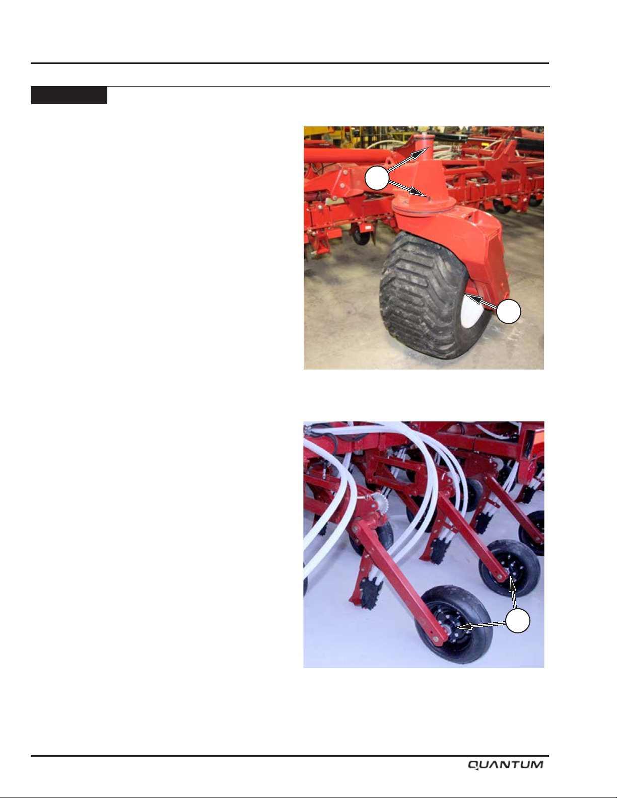
Maintenance
Lubrication
Greasing pivot points prevents wear and helps restrict
dirt from entering. However, once dirt does enter a
bearing, it combines with the lubricant and becomes an
abrasive grinding paste, more destructive than grit alone.
• Apply new lubricant frequently during operation to
ush out old contaminated lubricant.
• Use a good grade of lithium based grease.
• Use a good grade of machine oil.
• Clean grease ttings and lubricator gun before
applying lubricant.
Refer to the photos for grease tting locations.
1. Wheel Hubs
• Grease every 50 hours or seasonally, whichever
occurs rst.
2. Gauge Wheel Castor Pivot
• Grease every 50 hours.
2
1
3. Packer Wheel Hubs
• Grease every 50 hours or seasonally, whichever
occurs rst.
3
6-4 January 2019
Page 79
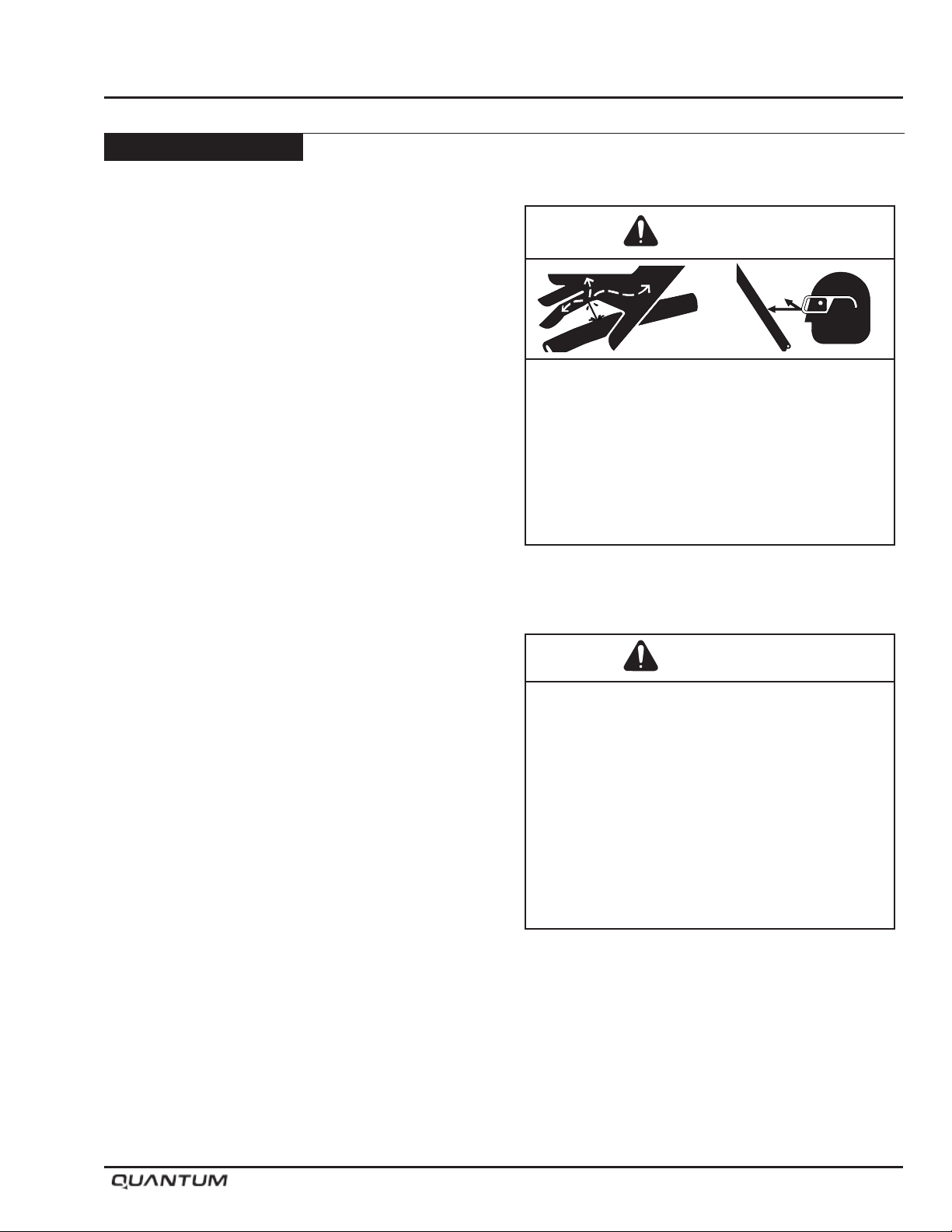
Opener Maintenance
Bushing Replacement
In the event the pivot pin bushings need replacing, use
the following procedure.
• Relieve all pressure from the opener circuit by
placing the tractor remote in “oat” position.
• Shut tractor engine off and ensure park brake is
engaged before proceeding.
• Place “Openers” ball valve into locked position to
prevent accidental oil ow to openers.
• Once the pressure is off of the opener circuit, the
opener can be disassembled as illustrated in diagram
on the following page.
Reverse the above procedure to reassemble trip.
Note: Bleed air from hydraulic circuit before using
unit. Refer to “Bleeding Hydraulic System”
for details.
Maintenance
Warning
HIGH-PRESSURE FLUID HAZARD
To prevent serious injury or death:
• Relieve pressure on hydraulic system before
servicing or disconnecting hoses.
• Wear proper hand and eye protection when
searching for leaks. Use wood or cardboard
instead of hands.
• Keep all components in good repair.
Cylinder Replacement
In the event the opener cylinder needs repair or
replacing, use the following procedure.
• Relieve all pressure from the opener circuit by
placing the tractor remote in “oat” position.
• Shut tractor engine off and ensure park brake is
engaged before proceeding.
• Place “Openers” ball valve into locked position to
prevent accidental oil ow to openers.
• Once the pressure is off of the opener circuit,
disconnect hydraulic hoses from opener cylinder.
• Refer to diagram on following page to remove the
pins from the opener cylinder.
• Remove the cylinder. Repair or replace cylinder as
necessary.
Reverse the above procedure to reassemble trip.
Note: Bleed air from hydraulic circuit before using
unit. Refer to “Bleeding Hydraulic System”
for details.
Warning
CRUSHING HAZARD
To prevent serious injury or death:
• Stand clear - openers move rapidly under
hydraulic pressure.
• Place valve in service position.
• Relieve pressure on hydraulic system before
servicing.
• Lower openers to ground before adjusting
depth.
• Shut tractor off and remove key.
January 2019 6-5
Page 80
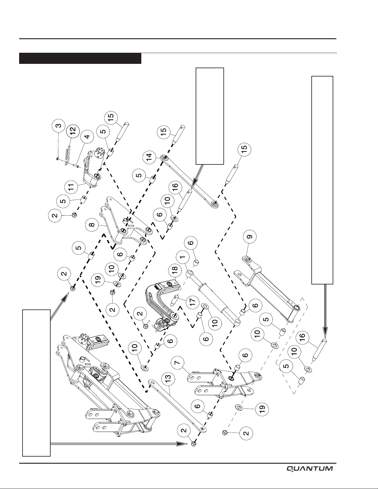
Maintenance
Opener Maintenance - Continued
Opener Body Assembly
Torque until there is no visible
and opener body.
gap between lower link clevis
Re-torque after initial 50 hours and periodically thereafter.
Torque to 65 lbs-ft. (88 Nm) Lower link should still rotate freely.
Torque until there is no visible gap between
prevent opener movement if over tightened.
upper links and opener body. Upper link will
6-6 January 2019
Page 81
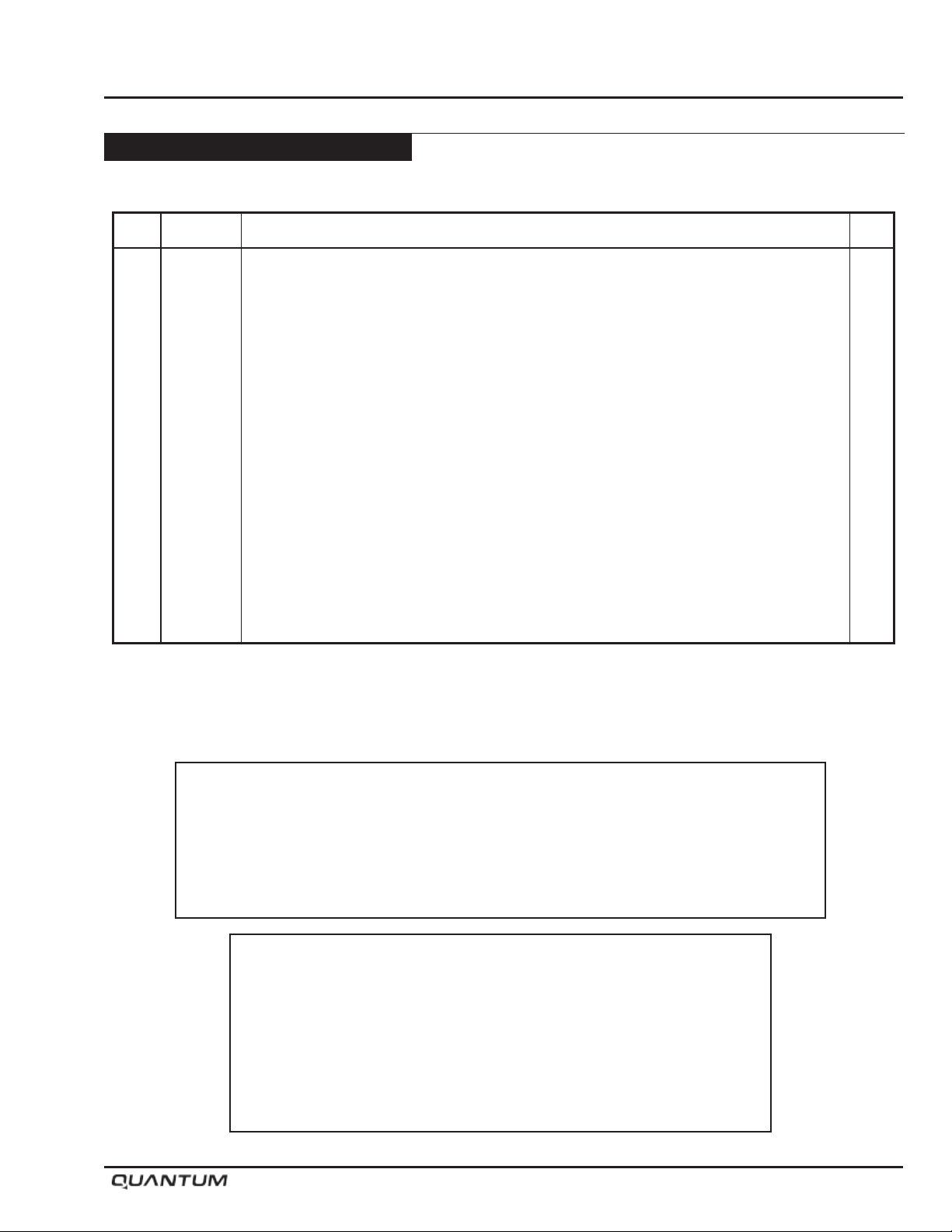
Maintenance
Opener Maintenance - Continued
Opener Body Assembly
Item Part No. Description Qty
1 C64546 Cylinder - 1 3/4 Bore x 4 Stroke ........................................................................................ 1
2 D-5273 Lock Nut - 3/4 Unitorque ................................................................................................... 6
3 D-5278 Lock Nut - 5/16 Flanged .................................................................................................... 1
4 N31012 Carriage Bolt - 5/16 x 1 1/4 Lg .......................................................................................... 1
5 S62986 Q2 Bushing - 1 ID x 1 1/8 OD x 1 1/2 Lg Nominal size ..................................................... 6
6 S62987 Q2 Bushing - 1 ID x 1 1/8 OD x 1 Lg Nominal size ........................................................... 8
7 S62998 Mounting Bracket - (Includes Item 5 Qty of 2) ................................................................... 1
8 S64119 Opener Body ..................................................................................................................... 1
9 S64172 Bottom Link ....................................................................................................................... 1
10 S64580 Washer - 1 1/32 ID x 2 OD x 1/8 ....................................................................................... 6
11 S64672 Packer Arm ........................................................................................................................ 1
12 S66251 Shim - Depth Adjustment - 1/4 Thick ................................................................................. 1
13 S64759 Strap - Top Link.................................................................................................................. 1
14 S65009 Top Link ............................................................................................................................. 1
15 S65037 Pin - 1 Dia x 4 21/32 UL (Includes W21776 Roll Pin) ........................................................ 3
16 S65038 Pin - 1 Dia x 5 9/16 UL (Includes W21776 Roll Pin) .......................................................... 2
17 S65039 Pin - 1 Dia x 1 29/32 UL (Includes W21776 Roll Pin) ........................................................ 1
18 S65048 Cast Shankholder - (Includes Item 6 Qty of 2) .................................................................. 1
19 D-5498 Washer - 1.062 ID x 2 OD x 11 GA .................................................................................... 2
Note: Openers should drop to the ground under their own weight, when the tractor
remote is placed into float position relieving oil pressure.
If it requires pressure to push an opener down to the ground during this
procedure, one or more of the pivot bolts are over tightened.
Check and adjust pivot bolts as required.
Important
Remove all pressure from hydraulic systems before attempting any
service work on hydraulic components.
Hydraulic system must be bled after it has been serviced (if any portion
of the system has been opened to atmosphere) and also on initial
start-up or if spongy or irregular trip operation is occurring.
January 2019 6-7
Page 82
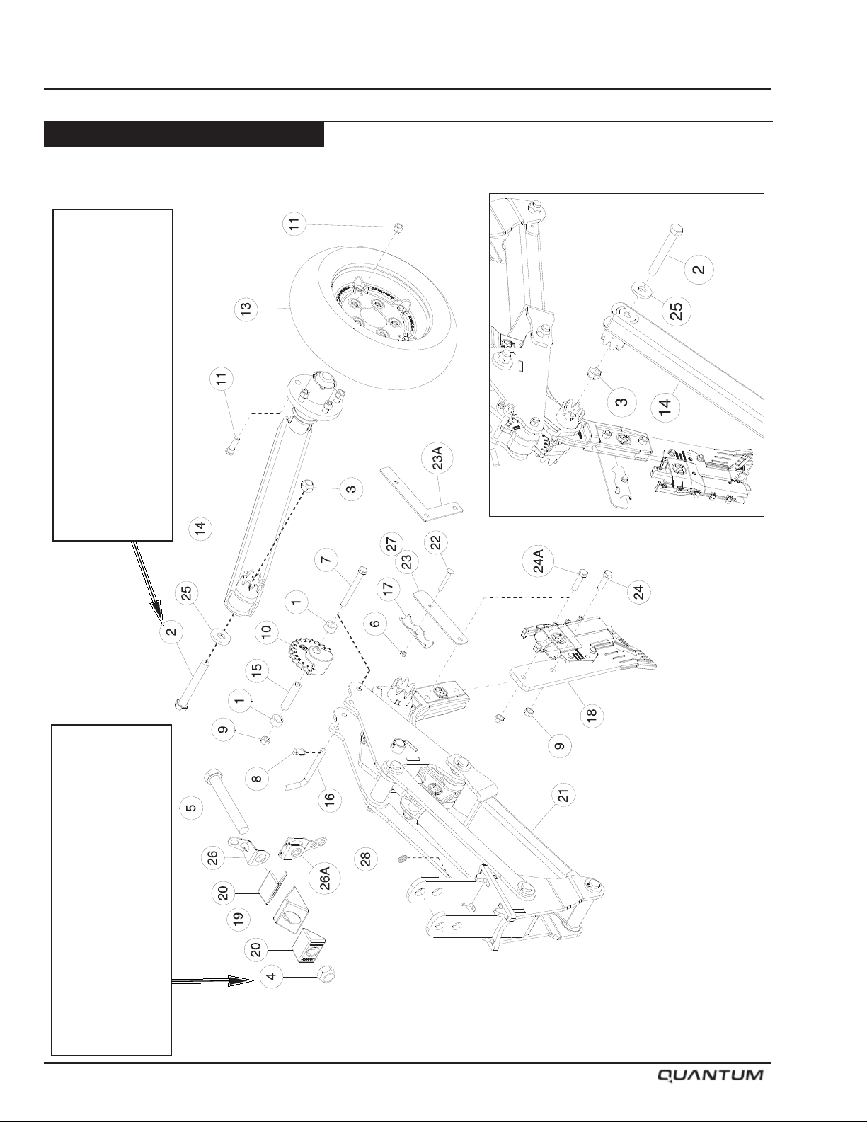
Maintenance
Opener Maintenance - Continued
Opener Assembly
Important
Re-torque locknut (2) after initial 50 hours
Torque 3/4” Bolt (2) to 250 ft. lbs. (339 Nm)
and periodically thereafter.
Important
6-8 January 2019
and periodically thereafter.
Re-torque locknut (4) after initial 50 hours
Torque 1” Locknut (4) to 400 ft. lbs. (542 Nm)
Page 83

Maintenance
Opener Maintenance - Continued
Opener Assembly
Item Part No. Description Qty
1 S65000 Cam Brace Bushing - 0.765 ID x 1-1/8 OD x 0.58 Lg ........................................................ 2
2 D-5558 Hex Bolt - 3/4 x 6 Lg.......................................................................................................... 1
3 D-5273 Lock Nut - 3/4 Unitorque ................................................................................................... 7
4 D-5274 Lock Nut - 1 Unitorque ...................................................................................................... 1
5 D12903 Hex Bolt - 1 x 7 Lg............................................................................................................. 1
6 D-5272 Lock Nut - 5/16 Unitorque ................................................................................................. 1
7 S66403 Hex Bolt - 1/2 x 4 1/2 Lg - GR.8 ........................................................................................ 1
8 S42294 Lynch Pin - 3/16 Dia x 1-3/8 Lg ......................................................................................... 1
9 S47110 Hex Nut - 1/2 Center Lock ................................................................................................. 3
10 S49260 Depth Cam - Cast ............................................................................................................. 1
11 S50246 Tapered Wheel Nut - 1/2-20UNF ....................................................................................... 5
12 S50247 Press-In Wheel Stud - 1/2 - 20UNF ................................................................................... 5
13 S64194 Otico Tire - 4 1/2 ................................................................................................................ 1
S64195 Otico Tire - 5 1/2 ................................................................................................................
14 S64673 Packer Arm ........................................................................................................................ 1
15 S64698 Bushing - 0.510 ID x 0.750 OD x 3.094 Lg ....................................................................... 1
16 S65061 Depth Pin - 1/2 Dia ............................................................................................................ 1
17 S65070 Hose Holder ...................................................................................................................... 1
18 S65121 Right Sideband Boot Kit - SHIELD CORE ........................................................................ 1
S65122 Left Sideband Boot Kit - SHIELD CORE
S65123 Paired Row Boot Kit - SHIELD CORE
* * * * * Single Shoot Boot Kit - SHIELD CORE
19 S66337 Cast Center Wedge - 3 wide ............................................................................................. 1
20 S66338 Cast Outer Wedge - 2 3/4 wide ......................................................................................... 2
21 S65650 Row Unit - Right (Includes items 1,2,3,7,8,9,10,11,12,14,15,16 and 25) ........................... 1
S65651 Row Unit - Left (Includes items 1,2,3,7,8,9,10,11,12,14,15,16 and 25) ..............................
22 S51466 Carriage Bolt - 5/16 x 2 Lg ................................................................................................ 1
23 S65851 Hose Holder Bracket - Cast Shankholder ......................................................................... 1
23A S68009 Hose Holder Bracket - Steel Shankholder
24 W-487 Hex Bolt - 1/2 x 1 3/4 Lg.................................................................................................... 2
24A S51464 Hex Bolt - 1/2 x 2 Lg - GR 8 (Hose Holder Replacement Bolt) ........................................ 1
25 S65821 Washer - 2 1/4 OD x 25/32 ID .......................................................................................... 1
26 S66245 Hose Holder - Opener ....................................................................................................... 1
26A S67170 Hose Holder - Opener - Low Profile - 4 per machine
27 S65852 Hose Holder Kit - Cast Shankholder - Contains Items 6, 9, 17, 22, 23 & 24A ................... 1
S68273 Hose Holder Kit - Steel Shankholder - Contains Items 6, 9, 17, 22, 23A & 24A
28 S66171 Openers Number Decal - 1 per machine
Important
Remove all pressure from hydraulic systems before attempting any service work on hydraulic
components.
Hydraulic system must be bled after it has been serviced (if any portion of the system
has been opened to atmosphere) and also on initial start-up or if spongy or irregular trip
operation is occurring.
January 2019 6-9
Page 84
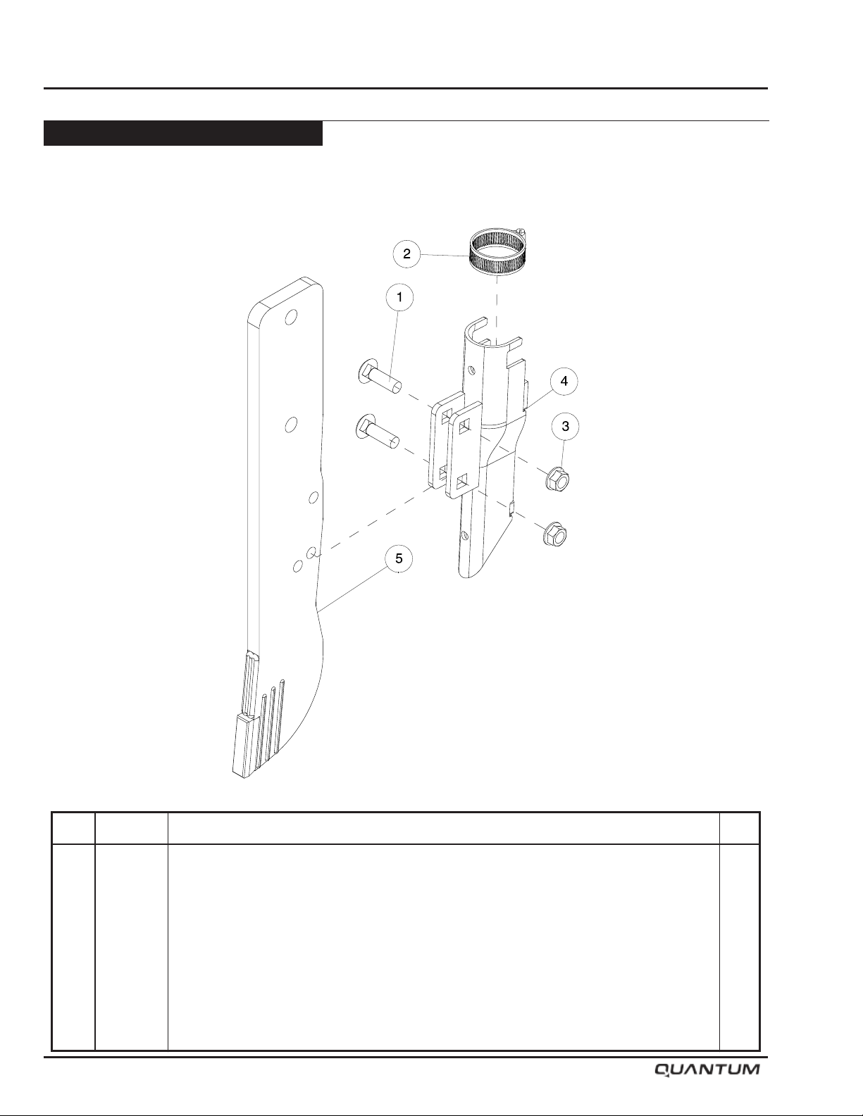
Maintenance
Opener Maintenance - Continued
Opener Assembly - Continued
Single Shoot Boot
Item Part No. Description Qty
1 D-5260 Carriage Bolt - 3/8 x 1-1/2 Lg ............................................................................................ 2
2 N11470 Hose Clamp ..................................................................................................................... 1
3 S27987 Center Lock Flange Lock Nut - 3/8 ................................................................................... 2
4 S42865 Single Shoot Boot ............................................................................................................. 1
5 S65405 Wear Shank W/Carbide - SHIELD CORE ......................................................................... 1
6-10 January 2019
Page 85
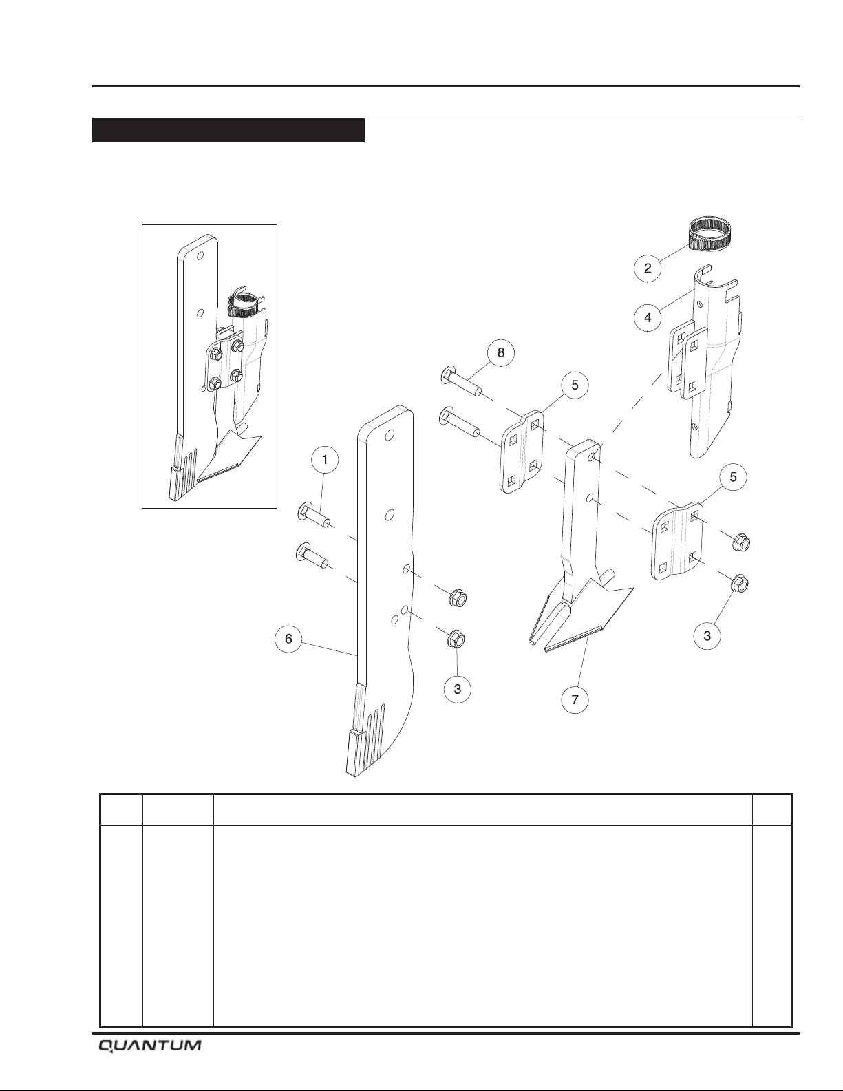
Opener Maintenance - Continued
Opener Assembly - Continued
Single Shoot Boot - 3” Spread
Maintenance
Item Part No. Description Qty
1 D-5260 Carriage Bolt - 3/8 x 1-1/2 Lg ............................................................................................ 2
2 N11470 Hose Clamp ...................................................................................................................... 1
3 S27987 Center Lock Flange Lock Nut - 3/8 .................................................................................. 4
4 S42865 Single Shoot Boot ............................................................................................................. 1
5 S45269 Mounting Plate .................................................................................................................. 2
6 S65405 Wear Shank W/Carbide - SHIELD CORE ......................................................................... 1
7 S47337 3” Wear Shovel ................................................................................................................. 1
8 S31980 Carriage Bolt - 3/8 x 1-3/4 Lg ............................................................................................ 2
January 2019 6-11
Page 86
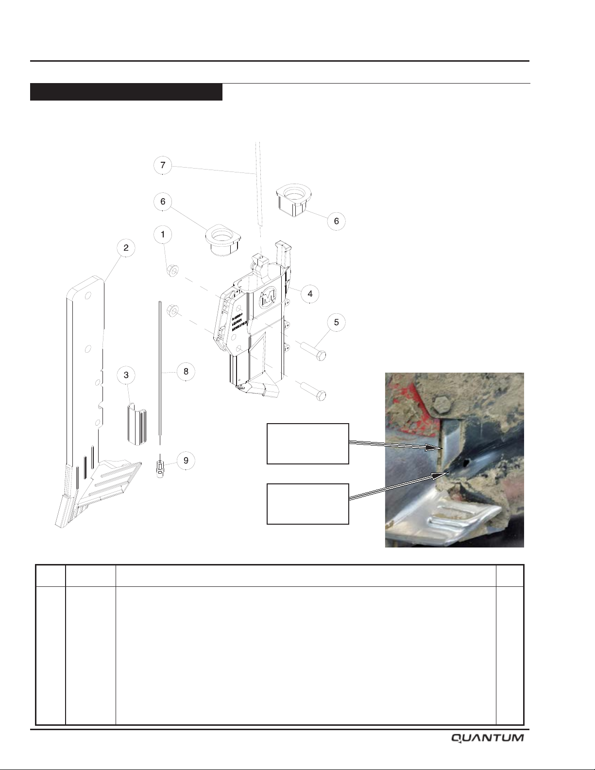
Maintenance
Opener Maintenance - Continued
Opener Assembly - Continued
IP Left Side Band Kit
Important
Check Wear Guards
regularly and replaced
before the IP Boot is
damaged.
Wear Guard
S65074
Damage to
IP Boot
Mount the side band openers with the deector and
seed tube facing the center of the Air Drill.
Item Part No. Description Qty
1 S27987 Lock Nut - 3/8 Flange W/Center Lock .............................................................................. 2
2 S65111 Sideband Shank - Left - SHIELD CORE ........................................................................... 1
3 S65074 Wear Guard - SHIELD CORE ........................................................................................... 1
4 S56482 IP (Injected Polymer) Left Sideband Seed Boot ................................................................ 1
5 W-477 Hex Bolt - 3/8 x 1 1/2 Lg.................................................................................................... 2
6 S47076 Secondary Hose Grommet ............................................................................................... 2
7 * * * * * Liquid Tube - 1/4 OD - See Liquid Kit Supplier for Tube ..................................................... 1
8 * * * * * Injector Tube - 1/8 OD - See NH3 Kit Supplier for Tube ..................................................... 1
9 S48814 Compression Fitting - 1/8 x 1/8 ......................................................................................... 1
S65122 IP Left Sideband Boot Kit (Contains Items 1, 2, 3, 4 & 5) ................................................. 1
6-12 January 2019
Page 87
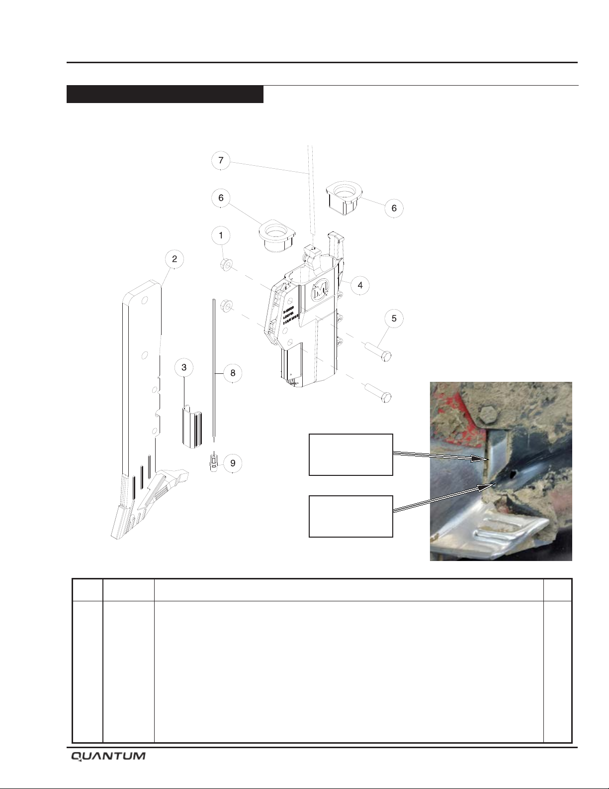
Opener Maintenance - Continued
Opener Assembly - Continued
IP Right Side Band Kit
Maintenance
Important
Check Wear Guards
regularly and replaced
before the IP Boot is
damaged.
Wear Guard
S65074
Damage to
IP Boot
Mount the side band openers with the deector and
seed tube facing the center of the Air Drill.
Item Part No. Description Qty
1 S27987 Lock Nut - 3/8 Flange W/Center Lock .............................................................................. 2
2 S65112 Sideband Shank - Right - SHIELD CORE ........................................................................ 1
3 S65074 Wear Guard - SHIELD CORE ........................................................................................... 1
4 S56483 IP (Injected Polymer) Right Sideband Seed Boot ............................................................. 1
5 W-477 Hex Bolt - 3/8 x 1 1/2 Lg.................................................................................................... 2
6 S47076 Secondary Hose Grommet ............................................................................................... 2
7 * * * * * Liquid Tube - 1/4 OD - See Liquid Kit Supplier for Tube ..................................................... 1
8 * * * * * Injector Tube - 1/8 OD - See NH3 Kit Supplier for Tube ..................................................... 1
9 S48814 Compression Fitting - 1/8 x 1/8 ......................................................................................... 1
S65121 IP Right Sideband Boot Kit (Contains Items 1, 2, 3, 4 & 5) ............................................... 1
January 2019 6-13
Page 88
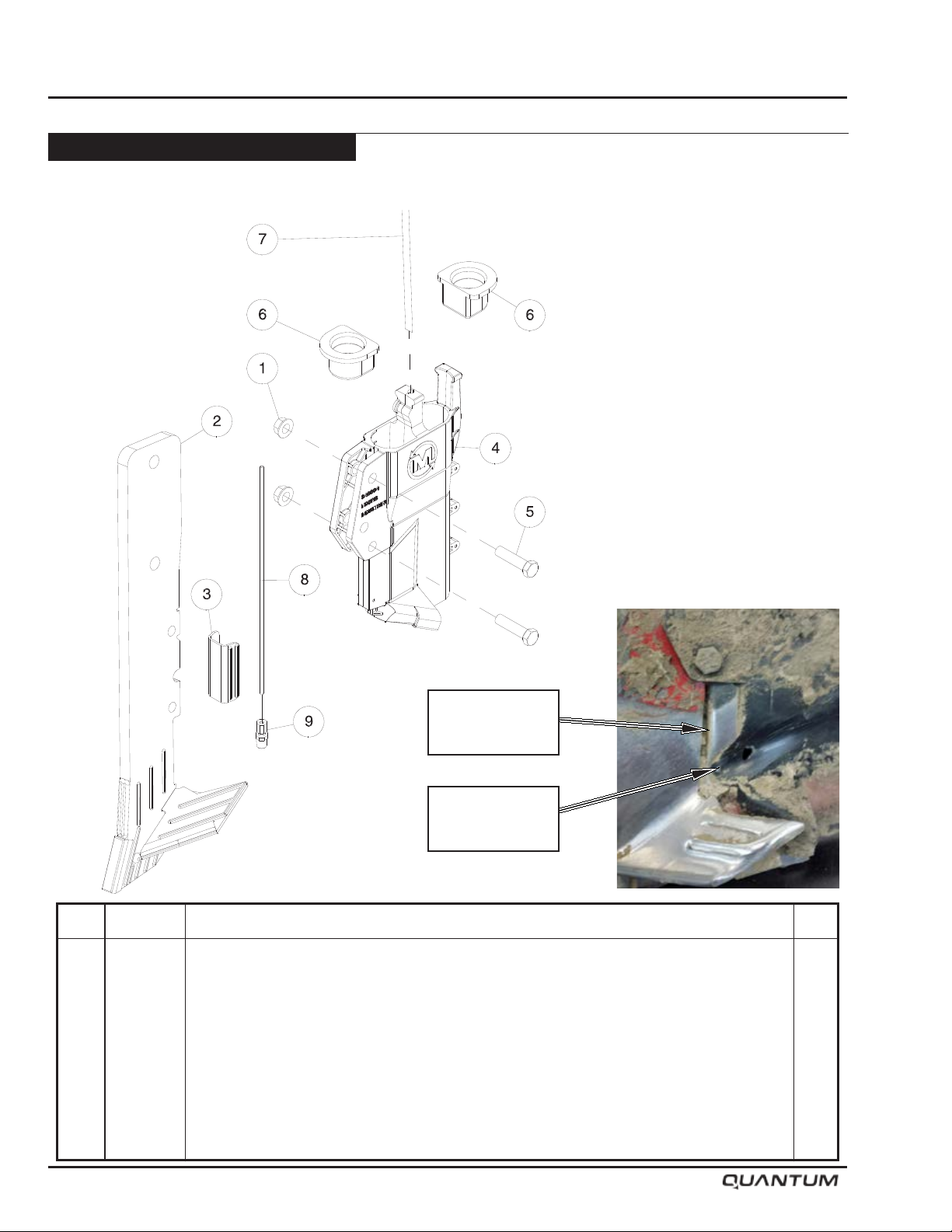
Maintenance
Opener Maintenance - Continued
Opener Assembly - Continued
IP Paired Row Kit
Important
Check Wear Guards
regularly and replaced
before the IP Boot is
damaged.
Wear Guard
S65074
Damage to
IP Boot
Item Part No. Description Qty
1 S27987 Lock Nut - 3/8 Flange W/Center Lock .............................................................................. 2
2 S62365 Paired Row Shank - SHIELD CORE ................................................................................. 1
3 S65074 Wear Guard - SHIELD CORE ........................................................................................... 1
4 S56485 IP (Injected Polymer) Paired Row Seed Boot .................................................................... 1
5 W-477 Hex Bolt - 3/8 x 1 1/2 Lg.................................................................................................... 2
6 S47076 Secondary Hose Grommet ............................................................................................... 2
7 * * * * * Liquid Tube - 1/4 OD - See Liquid Kit Supplier for Tube ..................................................... 1
8 * * * * * Injector Tube - 1/8 OD - See NH3 Kit Supplier for Tube ..................................................... 1
9 S48814 Compression Fitting - 1/8 x 1/8 ......................................................................................... 1
S65123 IP Paired Row Boot Kit - SHIELD CORE(Contains Items 1, 2, 3, 4 & 5) ........................... 1
6-14 January 2019
Page 89
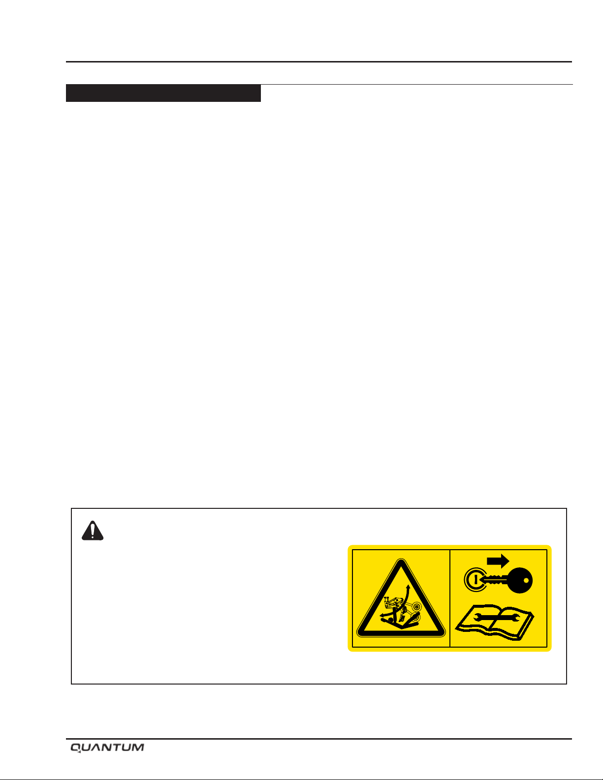
Opener Maintenance - Continued
Shank Replacement
In the event a shank needs replacing, use the following
procedure.
• Relieve all pressure from the opener circuit by
placing the tractor remote in “oat” position.
• Shut tractor engine off and ensure park brake is
engaged before proceeding.
• Place “Openers” ball valve into locked position to
prevent accidental oil ow to openers.
• Once the pressure is off of the opener circuit, remove
retaining bolts from shank holder. See diagram on
page 6-10.
• Remove shank from shank holder.
• Remove opener from shank.
• Reverse above procedure to reassemble.
Maintenance
Warning: Crushing Hazard
To prevent serious injury or death:
• Stand Clear - openers move rapidly under hydraulic
pressure.
• Before servicing hydraulics - Lower openers to ground
and relieve pressure from hydraulic system.
• Shut tractor off and remove key before servicing or
adjusting depth.
• Place “Openers” valve in locked position before adjusting
depth or servicing.
January 2019 6-15
S65155
Page 90
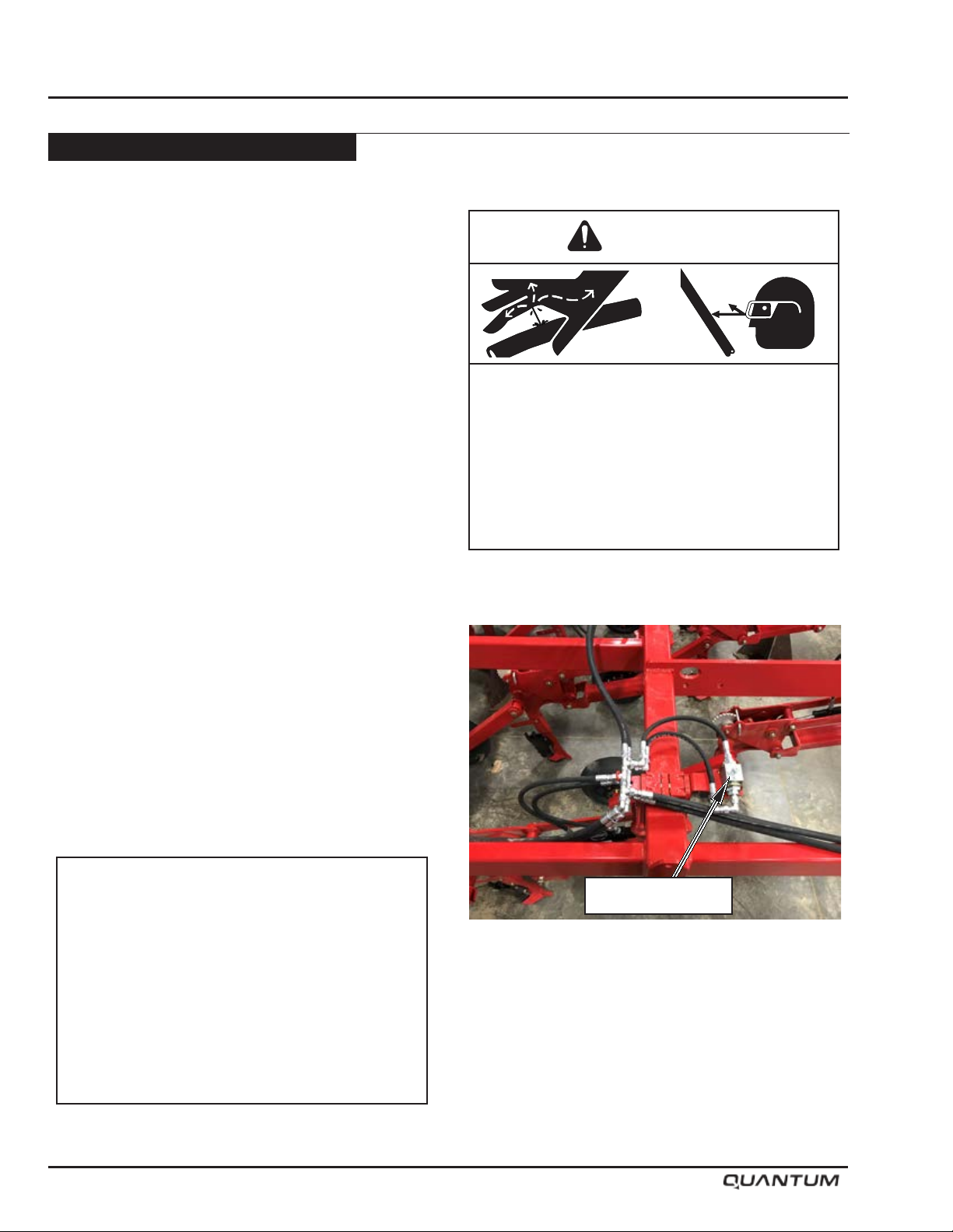
Maintenance
Opener Maintenance - Continued
Bleeding Hydraulic System
If hydraulic system has been serviced air will need to
be bleed out of system as follows:
To bleed hydraulic system of air:
• Controller / X35 must be turned OFF.
• Lift openers up and lock tractor remote in lift
position.
• With tractor hydraulics operating, open bleed-off
ball valves on end of drill wings.
• Allow oil to cycle for several minutes then change
direction of tractor remote to lower openers and
cycle for several more minutes.
• Close bleed-off ball valves and lift openers up.
• Repeat above procedure for a second time.
• Close bleed-off ball valves and lift openers up.
• Lock “Openers” valve and check to see that
openers stay rmly in position.
• If openers are spongy repeat procedure until air is
gone.
Warning
HIGH-PRESSURE FLUID HAZARD
To prevent serious injury or death:
• Relieve pressure on hydraulic system before
servicing or disconnecting hoses.
• Wear proper hand and eye protection when
searching for leaks. Use wood or cardboard
instead of hands.
• Keep all components in good repair.
Important
Remove all pressure from hydraulic systems
before attempting any service work on
hydraulic components.
Hydraulic system must be bled after it has
been serviced (if any portion of the system
has been opened to atmosphere).
And also on initial start-up or if spongy or
irregular trip operation is occurring.
6-16 January 2019
Bleed-Off Valve
Page 91
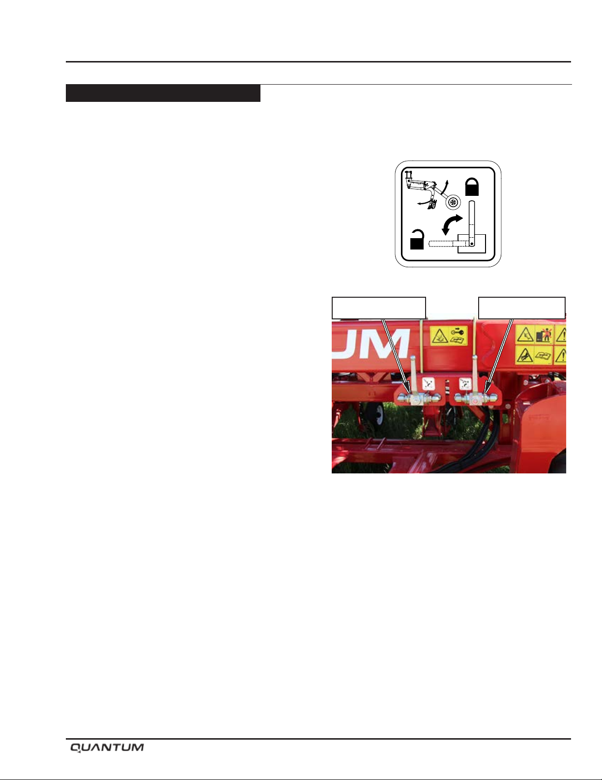
Opener Maintenance - Continued
Hydraulic System Trouble Shooting
If pressure can not be maintained in the hydraulic
system, or openers drop rapidly from transport position,
a leaky hydraulic cylinder (bypassing oil across the
piston seal) may be present. To locate a hydraulic leak
in the QUANTUM Air Drill hydraulic system, the following
procedure can be used:
1. Remove pressure from the hydraulic system.
2. Check the drill frame and hoses to make sure that
the leak is not external (leaking oil out of the circuit).
3. Lift the openers into their raised position.
4. Lock the opener hydraulic ball valve.
5. Watch the openers carefully across the drill and
locate the rst opener(s) to visibly drop down from
the raised position (NOTE: This is the general area
of the leaking cylinder, but the rst opener to drop is
not always the leaking cyinder.).
6. Unlock the “OPENERS” hydraulic ball valve and
lift the openers to the raised position and lock the
hydraulic remote in the raised position to apply ow
to the circuit for about ve minutes.
7. Let the hydraulic remote go back to neutral, shut off
the tractor, and then go and check the temperature
of the opener cylinders by feeling the cylinder barrels.
Start at the group of cylinders that were located in
step 5) and then work from the outer openers in to
center until a “hot” cylinder is located.
8. Under normal conditions the cylinders should remain
cool (ambient temperature or slightly above); the
opener with a “hot” cylinder barrel has the leaky seal
and should be serviced or replaced.
Maintenance
S65157
DECAL - S65157
Openers Valve Wing Valve
Valves in Locked Position
Note: All hydraulic cylinders have a natural leakage
rate. The openers on the QUANTUM drill
will drop over a long period of time during
storage; this is normal. Only check for
leaky cylinders if openers drop rapidly from
transport in a short period of time.
January 2019 6-17
Page 92
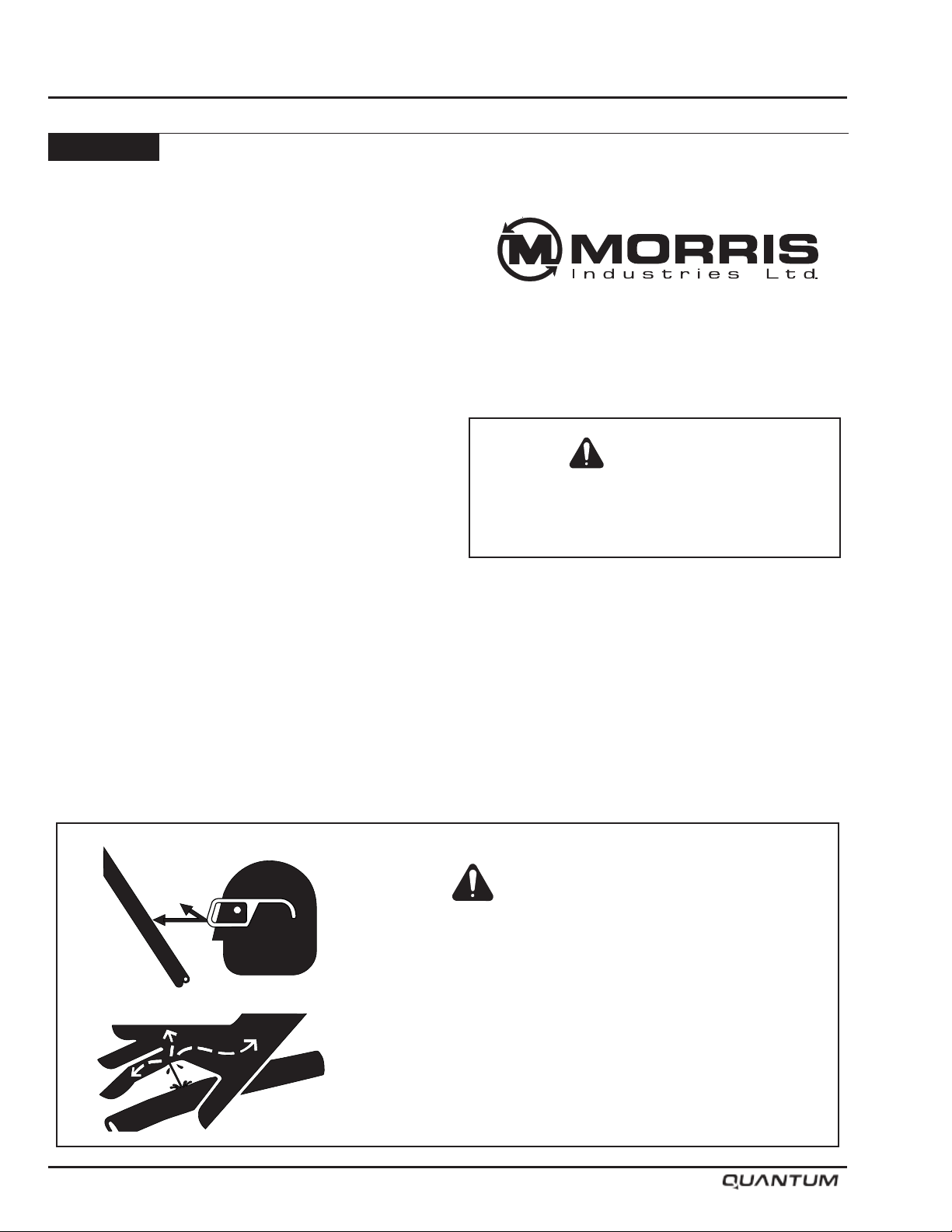
Maintenance
Hydraulics
Refer to Section 1 regarding hydraulic safety. In addition:
• Inspect hydraulic system for leaks, damaged
hoses and loose fittings. CRITICAL - ACTIVE
HYDRAULICS WILL CONTINUE TO LOOSE OIL
TO THE ATMOSHPERE/ENVIRONMENT IF A LEAK
GOES UNDETECTED - INSPECT REGULARLY.
• Damaged hoses and hydraulic tubing can only
be repaired by replacement. DO NOT ATTEMPT
REPAIRS WITH TAPE OR CEMENTS. High
pressure will burst such repairs and cause system
failure and possible injury.
• Always relieve hydraulic pressure from the system
before performing maintenance or repairs.
• Leaking cylinders - install a new seal kit.
• Fittings - use liquid Teon on all NPT hydraulic joints.
Do not use liquid Teon or Teon tape on JIC or
ORB ends.
• Hydraulic Hose Connections - when connecting the
hoses to the cylinders, tubing, etc. always use one
wrench to keep the hose from twisting and another
wrench to tighten the union. Excessive twisting will
shorten hose life.
• Keep ttings and couplers clean.
• Check the Tractor Manual for proper lter replacement
schedule.
Refer to the Trouble Shooting Section.
Contact your nearest Dealer for genuine repair parts.
Dealers carry ample stocks and are backed by the
manufacture and regional associations.
Caution
Dirt in the hydraulic system could damage
O-rings, causing leakage, pressure loss and
total system failure.
Note: Extreme care must be taken to maintain
a clean hydraulic system. Use only new
hydraulic fluid when filling reservoir.
HIGH-PRESSURE FLUID HAZARD
To prevent serious injury or death:
• Relieve pressure on hydraulic system before servicing or
disconnecting hoses.
• Wear proper hand and eye protection when searching for
leaks. Use wood or cardboard instead of hands.
• Keep all components in good repair.
6-18 January 2019
Warning
Page 93
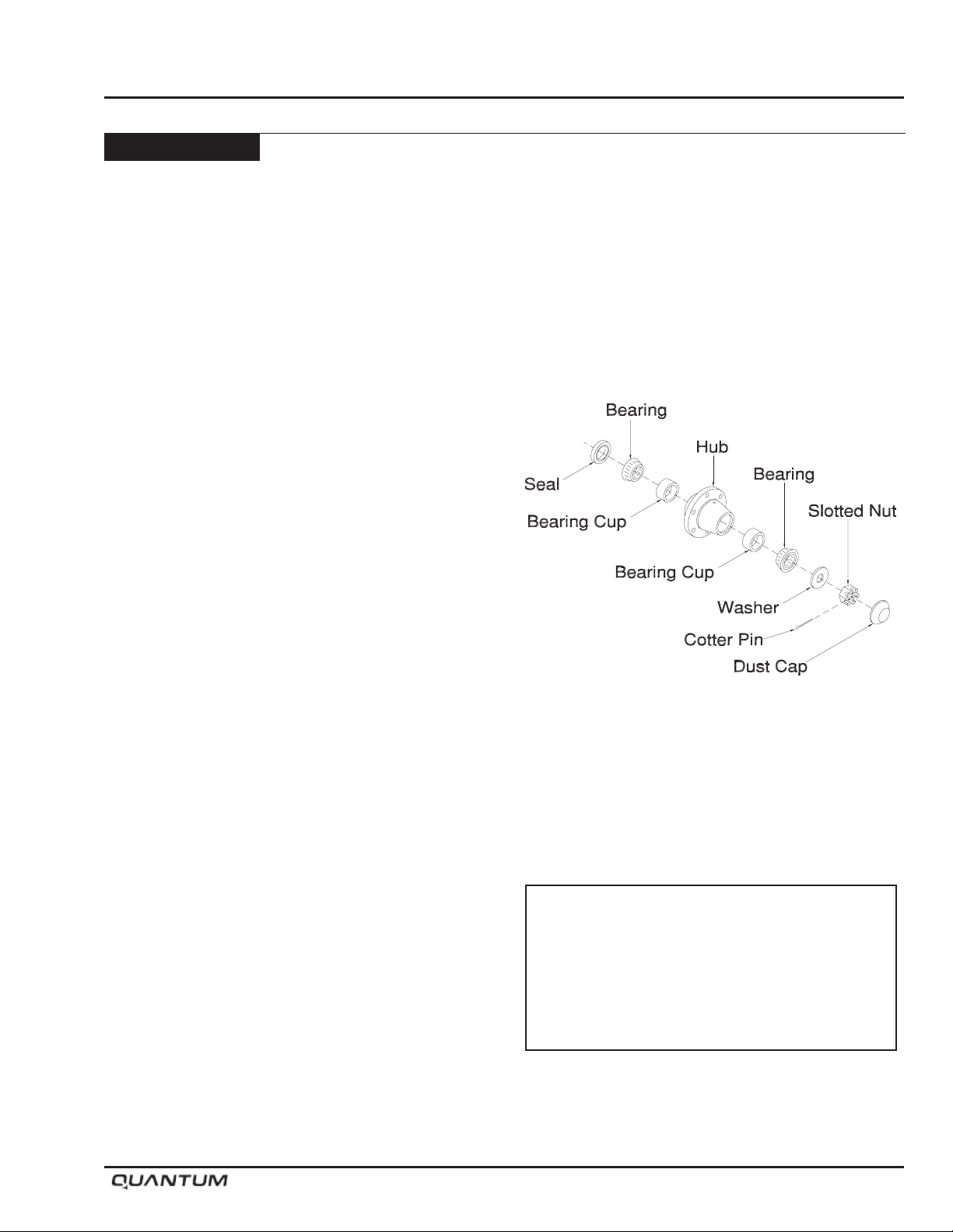
Wheel Bearings
Implement Hub
• Position implement in eld position.
• Shut tractor off, remove key, and engage park brake.
• Block wheel on tractor.
• Raise the implement wheel enough to clear the
surface.
• Securely block implement frame.
• Remove wheel from hub.
• Remove the dust cap, cotter pin, and the slotted nut
and washer.
• Be careful when pulling the hub off as not to drop
the outer bearing.
• Clean spindle and bearing components with solvent.
• Inspect for wear on bearings, spindle and cups,
replace parts as required.
• Do not reuse old seals. Use only new seals when
assembling.
• Pack inner hub with bearing grease.
• Be sure bearing and cup are dry and clean.
• Work grease into the bearing rollers, until each part
of the bearing is completely full of grease.
• Install inner bearing and cup rst, then press new
seals in place.
• Place hub on spindle.
• Install outer bearing, washer and slotted nut.
• Tighten nut while turning the wheel until a slight drag
is felt.
• Back nut off one slot and install a cotter pin. Bend
cotter pin up around nut.
• Pack grease inside the dust cap and tap into position.
Maintenance
Important
Check wheel bearings for play every
5,000 acres (2,000 hectares)
or yearly, which ever occurs first.
Tighten as required.
January 2019 6-19
Page 94
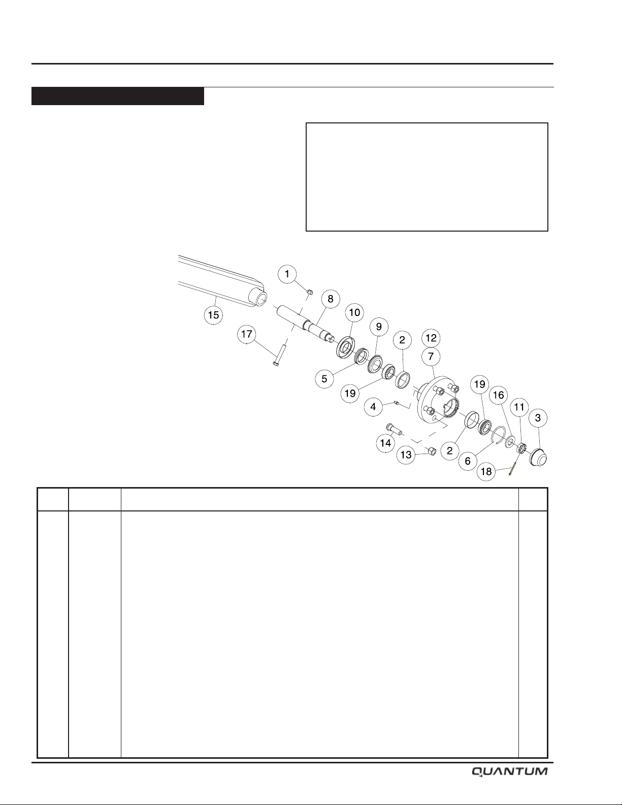
Maintenance
Wheel Bearings - Continued
Contour Opener Hub
• Position implement in eld position.
• Relieve all pressure from the opener circuit using
the tractor remote.
• Shut tractor engine off and remove key. Engage park
brake before proceeding.
• Place “Openers” ball valve into locked position to
prevent accidental oil ow to openers.
• Follow procedure for hub
removal and bearing
replacement outlined
under “Implement Hub”.
Important
Check wheel bearings for play every
5,000 acres (2,000 hectares)
or yearly, which ever occurs first.
Tighten as required.
Item Part No. Description Qty
1 M-3388 Lock Nut - 3/8 Unitorque ................................................................................................... 1
2 N14009 Bearing Cup ...................................................................................................................... 2
3 N14011 Dust Cap ........................................................................................................................... 1
4 S-752 Grease Zerk - 1/4 .............................................................................................................. 1
5 S48842 V-Seal - 1 1/4 Shaft ........................................................................................................... 1
6 S48843 Dust Cap Retaining Wire ................................................................................................... 1
7 S48844 Hub Casting - 1000 Lb - 5 Bolt .......................................................................................... 1
8 S48846 Spindle - 1-1/4 Dia ............................................................................................................ 1
9 S48847 Seal Counterface .............................................................................................................. 1
10 S48848 Seal Retainer .................................................................................................................... 1
11 S48849 Slotted Jam Nut - 3/4 ........................................................................................................ 1
12 S48850 Packer Hub Assembly (Includes Items# 2, 3, 4, 5, 6, 7, 8, 9, 10, 11, 13, 14, 16, 18 & 19) . 1
13 S50246 Tapered Wheel Nut - 1/2 .................................................................................................... 5
14 S50247 Press-In Wheel Stud - 1/2 ................................................................................................. 5
15 S64673 Packer Arm ........................................................................................................................ 1
16 W-476 Washer - 3/4 ...................................................................................................................... 1
17 W-479 Hex Bolt - 3/8 x 2 1/4 Lg.................................................................................................... 1
18 W-529 Cotter Pin - 1/8 x 1 Lg ....................................................................................................... 1
19 W-4187 Bearing Cone .................................................................................................................... 2
6-20 January 2019
Page 95

Section 7: Storage
Storage
Section 7:
Storage 7-1
Section Contents
Preparing for Storage ........................................................................................................ 7- 2
Wing Lift Cylinder Shaft Protection ................................................................................... 7- 3
Removing From Storage ................................................................................................... 7- 3
January 2019 7-1
Page 96
Storage
Preparing for Storage
• To insure longer life and satisfactory operation,
store the implement in a shed.
• If building storage is impossible, store away from
areas of main activity on rm, dry ground.
• Clean machine thoroughly.
• Inspect all parts for wear or damage.
• Avoid delays - if parts are required, order at the end
of the season.
• Lubricate grease ttings. (Refer to Maintenance
Section).
• Tighten all bolts to proper specications (Refer to
Maintenance Section).
• For a safer storage, lower the implement into eld
position and release the hydraulic pressure.
• If implement must be stored in a raised position,
ensure that wings are properly secured with lock
pins.
• Level implement using hitch jack and block up.
• Relieve pressure from hydraulic system.
• Cover tires with canvas to protect them from the
elements when stored outside.
• Coat exposed wing lift cylinder shafts (Refer to Wing
Lift Cylinder Shaft Protection).
• Paint any surfaces that have become worn.
Warning
Do not allow children to play
on or around the machine.
MORRIS PAINT
Part Number Description
W-4647 Red MORRIS Spray Can
N31087 White MORRIS Spray Can
Z-10 Red MORRIS Paint/Litre Can
7-2 January 2019
Page 97
Wing Lift Cylinder Shaft Protection
The steps summarized below should be followed when
protecting chrome plated shafting on equipment:
• Position the equipment as it will be stored, and
identify all the exposed portions of the chrome plated
shafts.
• Clean dirt and dust from the exposed portions of the
shafting using a dry cloth or a cloth which has been
dampened with an appropriate solvent.
• Prepare a mixture of 60% oil-based rust inhibitor and
40% Kerosene. Apply a thin coating of this mixture to
the exposed surfaces of the chrome plated shafting.
No. 1 fuel oil may be substituted for Kerosene. A
cloth dipped in the mixture can be used to apply the
coating.
• Inspect the shaft surfaces after six months and apply
additional corrosion preventative mixture.
• If the equipment is to be moved and then stored
again for an extended period of time, the steps above
should be repeated for all shafts that were stroked
during the move.
• Before retracting the cylinders the protective
coating should be removed, to prevent ne sand
and dirt that has accumulated in the coating, from
damaging the shaft seal. Under no circumstances
should sandpaper or other abrasive be used
to clean the surfaces. Plastic or copper wool in
combination with an appropriate solvent will remove
most of the dirt.
Storage
Caution
Dirt in the hydraulic system could damage
O-rings, causing leakage, pressure loss and
total system failure.
Removing From Storage
• Review Operator’s Manual.
• Check tire pressure (Refer to Tire Pressure List)
• Clean machine thoroughly. Remove coating from
exposed cylinder shafts (Refer to Wing Lift Cylinder
Shaft Protection).
• Lubricate grease fittings. (Refer to Lubricating
Section).
• Tighten all bolts to proper specications (Refer to
Bolt Torque Chart).
January 2019 7-3
Page 98

Storage
Notes
7-4 January 2019
Page 99

Section 8: Troubleshooting
Troubleshooting
Section 8:
Troubleshooting 8-1
Section Contents
Machine not operating straight. .................................................................................... 8-2
Lack of penetration. ...................................................................................................... 8-2
Openers wearing unevenly ........................................................................................... 8-2
Wing lifting too slowly. ................................................................................................... 8-2
Wings not lowering. ...................................................................................................... 8-2
One wing will lift, other will not. .................................................................................... 8-2
Oil accumulation. .......................................................................................................... 8-2
Openers drop quickly after transport lock valve is closed. ............................................ 8-2
Openers won’t lift or lower. ............................................................................................ 8-3
Openers won’t lift. ......................................................................................................... 8-3
Opener pressure won’t change. ................................................................................... 8-3
Openers can not be fully pressurized. .......................................................................... 8-3
Openers not fully lifting to transport position. ................................................................ 8-4
Excessive seed depth and soil throw. ........................................................................... 8-4
Shanks hang back and trip out during normal operation. ............................................. 8-4
Seed rows covered in loose soil after seeding. ............................................................. 8-4
Packer wheels bounce and chatter excessively in field. ............................................... 8-4
January 2019 8-1
Page 100

Troubleshooting
Problem
Machine not operating straight.
Lack of penetration.
Openers wearing unevenly
Wing lifting too slowly.
Cause
Uneven opener depth.
Openers worn.
System pressure too low.
Tire tracks.
Front row always wears more
than the others.
Tractor hydraulic pressure.
Hydraulic breakaways.
Hose restriction.
Correction
Refer to Operation Section on depth adjustment.
Check tire pressure.
Replacement necessary.
Refer to Operation Section on setting maximum
system pressure.
Replace worn openers.
Repair pump. Pressure relief valve needs resetting.
Foreign material or sticking.
Check compatibility.
Cylinder linkage binding.
Wings not lowering.
One wing will lift, other will not.
Oil accumulation.
Openers drop quickly after transport lock valve is closed.
Transport valve in locked position.
Assembly.
Restriction in line.
Internal cylinder leak.
Damaged seal.
Loose fittings.
Scored cylinder shaft will damage
shaft seal.
Normal.
Hydraulic line, fitting or cylinder
leak.
Place opener valve into unlocked position.
Hoses reversed at cylinder.
Clean.
Repair cylinder.
Replace seals.
Tighten hose and pipe connections.
Replace.
Slight seepage from seal is normal.
Locate leaking line, fitting or cylinder and repair
or replace.
8-2 January 2019
 Loading...