


 Loading...
Morii-Seiiki NH4000 DCG, NH5000, NH5000 DCG, NH6300 DCG, NH8000 DCG INSTRUCTION MANUAL
...INSTRUCTION MANUAL
Applicable Model
NH4000 DCG
NH5000
NH5000 DCG
NH6300 DCG
NH8000 DCG
NV4000
Applicable Specification
Carrier Pallet Pool System
Applicable NC Unit
MSG-501 MSX-501 MSX-502 MSX-701 MSX-711
MSG-502 MSX-501III MSX-502III MSX-701III MSX-711III
Before starting operation, maintenance, or programming, carefully read the manuals supplied by Mori Seiki, the NC unit manufacturer, and equipment manufacturers so that you fully understand the information they contain.
Keep the manuals carefully so that they will not be lost.
PPM-NHCPP-C1EN

•The contents of this manual are subject to change without notice due to improvements to the machine or in order to improve the manual. Consequently, please bear in mind that there may be slight discrepancies between the contents of the manual and the actual machine. Changes to the instruction manual are made in revised editions which are distinguished from each other by updating the instruction manual number.
•Should you discover any discrepancies between the contents of the manual and the actual machine, or if any part of the manual is unclear, please contact Mori Seiki and clarify these points before using the machine. Mori Seiki will not be liable for any damages occurring as a direct or indirect consequence of using the machine without clarifying these points.
•All rights reserved: reproduction of this instruction manual in any form, in whole or in part, is not permitted without the written consent of Mori Seiki.
The product shipped to you (the machine and accessory equipment) has been manufactured in accordance with the laws and standards that prevail in the relevant country or region. Consequently it cannot be exported, sold, or relocated, to a destination in a country with different laws or standards.
The export of this product is subject to an authorization from the government of the exporting country.
Check with the government agency for authorization.
990730
SIGNAL WORD DEFINITION
A variety of symbols are used to indicate different types of warning information and advice.
Learn the meanings of these symbols and carefully read the explanation to ensure safe operation while using this manual.
<Symbols related with warning>
The warning information is classified into three categories, DANGER, WARNING, and CAUTION. The following symbols are used to indicate the level of danger.
DANGER Indicates an imminently hazardous situation which, if not avoided, will result in death or serious injury.
The information described in the DANGER frame must be strictly observed.
WARNING Indicates a potentially hazardous situation which, if not avoided, could result in death or serious injury.
The information described in the WARNING frame must be strictly observed.
CAUTION Indicates a potentially hazardous situation which, if not avoided, may result in minor or
moderate injury or damages to the machine.
The information described following the caution symbol must be strictly observed.
<Other symbols>
Indicates the items that must be taken into consideration.
NOTE
Indicates useful guidance relating to operations.
Indicates the page number or manual to be referred to.
The number in ( ) indicates the section number.

CONTENTS
1 |
OVERVIEW . . |
. . . . . . . . . . . . . . . . . . . . . . . . . . . . . . . . . . . . . . . . . . . . . . . . . . . . . . . . |
. P-1 |
|
2 SCHEMATIC DIAGRAM OF PALLET POOL SYSTEM. . . . . . . . . . . . . . . . . . . . . . . . . . |
P-2 |
|||
3 |
PALLET TRANSPORT PROCESSING . . . . . . . . . . . . . . . . . . . . . . . . . . . . . . . . . . . . . . |
P-4 |
||
|
3-1 Pallet Transport Processing Flowchart . . . . . . . . . . . . . . . . . . . . . . . . . . . . . . . . . |
P-4 |
||
|
3-2 |
Pallet Transport Flow . . . . . . . . . . . . . . . . . . . . . . . . . . . . . . . . . . . . . . . . . . . . . . |
P-6 |
|
|
3-3 Urgent Workpieces (Interruption Processing) . . . . . . . . . . . . . . . . . . . . . . . . . . . . |
P-8 |
||
|
|
3-3-1 |
Interruption Method . . . . . . . . . . . . . . . . . . . . . . . . . . . . . . . . . . . . . . . . . |
P-8 |
|
|
3-3-2 |
Interruption Operation . . . . . . . . . . . . . . . . . . . . . . . . . . . . . . . . . . . . . . . |
P-8 |
4 |
DATA SETTING SCREENS . . . . . . . . . . . . . . . . . . . . . . . . . . . . . . . . . . . . . . . . . . . . . . |
P-9 |
||
|
4-1 |
Screen Trees. . . . . . . . . . . . . . . . . . . . . . . . . . . . . . . . . . . . . . . . . . . . . . . . . . . . . |
P-9 |
|
|
4-2 |
PCMDI MENU Screen. . . . . . . . . . . . . . . . . . . . . . . . . . . . . . . . . . . . . . . . . . . . . |
P-11 |
|
|
4-3 |
WORK NUMBER Screen . . . . . . . . . . . . . . . . . . . . . . . . . . . . . . . . . . . . . . . . . . |
P-11 |
|
|
|
4-3-1 Description of Pallet Statuses . . . . . . . . . . . . . . . . . . . . . . . . . . . . . . . . |
P-18 |
|
|
4-4 SETUP STATION PALLET CALL Screen . . . . . . . . . . . . . . . . . . . . . . . . . . . . . . |
P-21 |
||
|
4-5 WORK NUMBER (SUB) Screen . . . . . . . . . . . . . . . . . . . . . . . . . . . . . . . . . . . . . |
P-22 |
||
|
4-6 |
PALLET DATA Screen. . . . . . . . . . . . . . . . . . . . . . . . . . . . . . . . . . . . . . . . . . . . . |
P-23 |
|
5 SETUP STATION OPERATION PANEL . . . . . . . . . . . . . . . . . . . . . . . . . . . . . . . . . . . . |
P-24 |
|||
|
5-1 Setup Station Operation Panel . . . . . . . . . . . . . . . . . . . . . . . . . . . . . . . . . . . . . . |
P-24 |
||
|
5-2 Switches on the Operation Panels . . . . . . . . . . . . . . . . . . . . . . . . . . . . . . . . . . . |
P-25 |
||
|
|
5-2-1 |
EMERGENCY STOP Button . . . . . . . . . . . . . . . . . . . . . . . . . . . . . . . . . |
P-25 |
|
|
5-2-2 |
LINK/INDE. Selection Switch . . . . . . . . . . . . . . . . . . . . . . . . . . . . . . . . . |
P-25 |
|
|
5-2-3 |
ALARM Indicator . . . . . . . . . . . . . . . . . . . . . . . . . . . . . . . . . . . . . . . . . . |
P-25 |
|
|
5-2-4 |
ALARM RESET Switch . . . . . . . . . . . . . . . . . . . . . . . . . . . . . . . . . . . . . |
P-25 |
|
|
5-2-5 |
SETUP Switches . . . . . . . . . . . . . . . . . . . . . . . . . . . . . . . . . . . . . . . . . . |
P-26 |
6 STARTING THE APC AND PALLET POOL . . . . . . . . . . . . . . . . . . . . . . . . . . . . . . . . . |
P-27 |
|||
|
6-1 Starting with the M02/M30. . . . . . . . . . . . . . . . . . . . . . . . . . . . . . . . . . . . . . . . . . |
P-27 |
||
|
6-2 Starting with the M60/M61. . . . . . . . . . . . . . . . . . . . . . . . . . . . . . . . . . . . . . . . . . |
P-28 |
||
|
6-3 Starting Using the APC START Switch (Option) . . . . . . . . . . . . . . . . . . . . . . . . . |
P-28 |
||
|
6-4 Starting from the SETUP STATION PALLET CALL Screen . . . . . . . . . . . . . . . . |
P-28 |
||
|
6-5 Starting Using the Buttons on the Setup Station Operation Panel . . . . . . . . . . . |
P-28 |
||
|
6-6 SYSTEM LINK/INDE. Selection Switch. . . . . . . . . . . . . . . . . . . . . . . . . . . . . . . . |
P-29 |
||
|
|
|
|
|

6-7 Operation of the Setup Station . . . . . . . . . . . . . . . . . . . . . . . . . . . . . . . . . . . . . . P-29
6-7-1 Single Pallet Operation . . . . . . . . . . . . . . . . . . . . . . . . . . . . . . . . . . . . . P-29
6-7-2 Multiple Pallet Operation . . . . . . . . . . . . . . . . . . . . . . . . . . . . . . . . . . . . P-29
7 TABLE CLAMP/UNCLAMP FOOTSWITCH AT THE SETUP STATION . . . . . . . . . . . . P-30
8 SETUP STATION DOOR LOCK CONDITIONS . . . . . . . . . . . . . . . . . . . . . . . . . . . . . . P-30
9 AUTOMATIC POWER SHUTOFF . . . . . . . . . . . . . . . . . . . . . . . . . . . . . . . . . . . . . . . . . P-30
10 AUTO-COUPLER (OPTION). . . . . . . . . . . . . . . . . . . . . . . . . . . . . . . . . . . . . . . . . . . . . P-31
10-1 Operating the Auto-coupler . . . . . . . . . . . . . . . . . . . . . . . . . . . . . . . . . . . . . . . . . P-31
11 MAINTENANCE . . . . . . . . . . . . . . . . . . . . . . . . . . . . . . . . . . . . . . . . . . . . . . . . . . . . . . P-31
11-1 Recovering Interrupted Pallet Pool Operation. . . . . . . . . . . . . . . . . . . . . . . . . . . P-31
APPENDIX 1 HANDY OPERATION PANEL . . . . . . . . . . . . . . . . . . . . . . . . . . . APPENDIX-1
1-1 Manual Pallet Pool Operation Mode ON/OFF Switch . . . . . . . . . . . . . . APPENDIX-2 1-2 Emergency Stop Button . . . . . . . . . . . . . . . . . . . . . . . . . . . . . . . . . . . . APPENDIX-3 1-3 Selecting the Operation Mode. . . . . . . . . . . . . . . . . . . . . . . . . . . . . . . . APPENDIX-3 1-4 Registering Position Data of the A.G.V. and the Fork . . . . . . . . . . . . . . APPENDIX-6
APPENDIX 2 OPERATION USING MANUAL OPERATION SCREENS . . . . . . APPENDIX-9
2-1 Pallet Pool Operation Screen . . . . . . . . . . . . . . . . . . . . . . . . . . . . . . . . APPENDIX-9
2-1-1 PCMDI MENU Screen . . . . . . . . . . . . . . . . . . . . . . . . . . . . . . APPENDIX-9
2-1-2 MANUAL OPERATION Menu Screen. . . . . . . . . . . . . . . . . . APPENDIX-10
2-1-3 MANUAL OPERATION Screens . . . . . . . . . . . . . . . . . . . . . . APPENDIX-11
2-1-4 A.G.V. INDEX Screen . . . . . . . . . . . . . . . . . . . . . . . . . . . . . . APPENDIX-13
2-1-5 MAINTENANCE DOOR Screen . . . . . . . . . . . . . . . . . . . . . . APPENDIX-14
2-1-6 ZERO RETURN Screen . . . . . . . . . . . . . . . . . . . . . . . . . . . . APPENDIX-15
2-1-7 STATUS DISPLAY Screen . . . . . . . . . . . . . . . . . . . . . . . . . . APPENDIX-16
2-2 Pallet Pool Operation Using MANUAL OPERATION Screens . . . . . . APPENDIX-17 2-2-1 FORK CENTER Operation . . . . . . . . . . . . . . . . . . . . . . . . . . APPENDIX-19
2-2-2 FORK FORWARD Operation . . . . . . . . . . . . . . . . . . . . . . . . APPENDIX-19
2-2-3 FORK UP/FORK DOWN Operation . . . . . . . . . . . . . . . . . . . APPENDIX-19
2-2-4 SHUTTER OPEN/SHUTTER CLOSE Operation . . . . . . . . . APPENDIX-19

2-3 A.G.V. Indexing Using A.G.V. INDEX Screen . . . . . . . . . . . . . . . . . . . APPENDIX-20 2-4 Maintenance Door Locking/Unlocking Operation . . . . . . . . . . . . . . . . APPENDIX-21 2-4-1 MAINTENANCE DOOR LOCK Operation . . . . . . . . . . . . . . APPENDIX-21 2-4-2 MAINTENANCE DOOR UNLOCK Operation . . . . . . . . . . . . APPENDIX-21 2-5 Zero Return Operation . . . . . . . . . . . . . . . . . . . . . . . . . . . . . . . . . . . . APPENDIX-22 2-5-1 A.G.V. ZERO RETURN Operation . . . . . . . . . . . . . . . . . . . . APPENDIX-22 2-5-2 FORK FOR./BACK ZERO RETURN Operation . . . . . . . . . . APPENDIX-23 2-5-3 A.G.V. + DIRECTION FEED Operation. . . . . . . . . . . . . . . . . APPENDIX-23 2-5-4 A.G.V. − DIRECTION FEED Operation . . . . . . . . . . . . . . . . . APPENDIX-24 2-5-5 FORK FOR./BACK + FEED Operation . . . . . . . . . . . . . . . . . APPENDIX-24 2-5-6 FORK FOR./BACK − FEED Operation . . . . . . . . . . . . . . . . . APPENDIX-25
2-6 Releasing Manual Operation Interlock . . . . . . . . . . . . . . . . . . . . . . . . APPENDIX-26
APPENDIX 3 MAINTENANCE OPERATION . . . . . . . . . . . . . . . . . . . . . . . . . . APPENDIX-27
3-1 Adjustment at Start-up. . . . . . . . . . . . . . . . . . . . . . . . . . . . . . . . . . . . . APPENDIX-27
APPENDIX 4 OPERATION OF AUTO-COUPLER (OPTION) . . . . . . . . . . . . . APPENDIX-29
APPENDIX 5 PC-BASED (MCC-LPS) CONTROL (OPTION) . . . . . . . . . . . . . APPENDIX-30
5-1 Schematic Diagram of Pallet Pool System . . . . . . . . . . . . . . . . . . . . . APPENDIX-30
5-2 Station Numbers . . . . . . . . . . . . . . . . . . . . . . . . . . . . . . . . . . . . . . . . . APPENDIX-31
5-3 Data Table Numbers . . . . . . . . . . . . . . . . . . . . . . . . . . . . . . . . . . . . . . APPENDIX-32
5-4 Parameters . . . . . . . . . . . . . . . . . . . . . . . . . . . . . . . . . . . . . . . . . . . . . APPENDIX-32
P-1
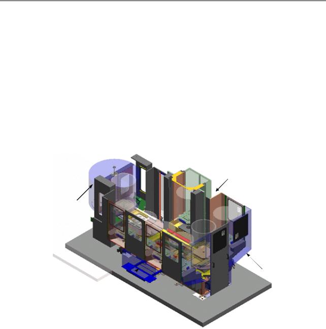
1 OVERVIEW
The carrier pallet pool system operates according to the priority order determined by the operator for setup and machining. For an urgent request, the system is able to respond to the request by allowing the setup and machining for the urgent workpieces by interrupting the predetermined order.
The system is most appropriate for repetitive production of medium lot with medium variety of kinds of workpieces.
Since the pallet pool indexing is controlled in the random method, a total of "number of stockers + 1" pallets can be set in the system.
In this instruction manual, "one machine + one setup station + one pallet pool" system with PMC control is taken as an example for explanations.
Setup station
Machine setup station
Splash guard
Pallet pool electrical cabinet
Machine image (longitudinal arrangement specification)
P-2
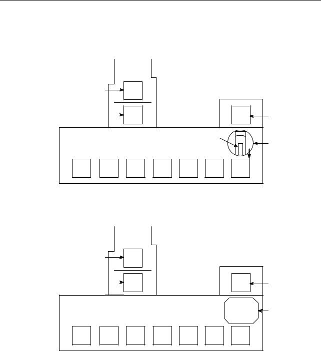
2 SCHEMATIC DIAGRAM OF PALLET POOL SYSTEM
<Layout diagram of 8-station traversal arrangement specification (NH4000 DCG)>
|
|
Machine |
|
|
|
|
|
In-machine station |
|
12 |
|
|
|
|
|
Standby station |
|
11 |
|
|
|
01 |
Setup station |
|
|
|
|
|
Pallet |
|
A.G.V. |
|
|
|
|
|
|
|
|
31 |
32 |
33 |
34 |
35 |
36 |
37 |
|
<Layout diagram of 8-station traversal arrangement specification (NH5000/NH5000 DCG)>
|
|
Machine |
|
|
|
|
|
In-machine station |
|
12 |
|
|
|
|
|
Standby station |
|
11 |
|
|
|
01 |
Setup station |
|
|
|
|
|
|
|
A.G.V. |
31 |
32 |
33 |
34 |
35 |
36 |
37 |
|
P-3
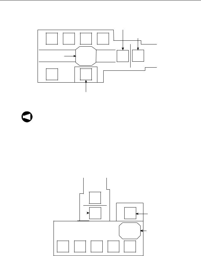
<Layout diagram of 6-station longitudinal arrangement specification (NH5000/NH5000 DCG)>
|
|
|
Standby station |
|
|
34 |
33 |
32 |
31 |
In-machine station |
|
|
|
||||
A.G.V. |
|
|
11 |
12 |
Machine |
|
|
|
|||
35 |
|
01 |
|
|
|
Setup station
NOTE
1. The numbers given in the diagram above indicate the station numbers. Pallet transport is controlled according to these station numbers.
2.Depending on the system specification, the layout of the machine, stockers and the setup station may differ from the ones shown above.
3.When loading or unloading a pallet to or from the machine or a station, turn the A.G.V to the direction of loading or unloading the pallet. (The fork can only be moved in the positive direction to transfer a pallet.)
<Layout diagram of 6-station traversal arrangement specification (NV4000)>
Machine
In-machine station  12
12
Standby station |
11 |
01 |
Setup station |
|
|
|
|
A.G.V. |
31 |
32 |
33 |
34 |
35 |
P-4
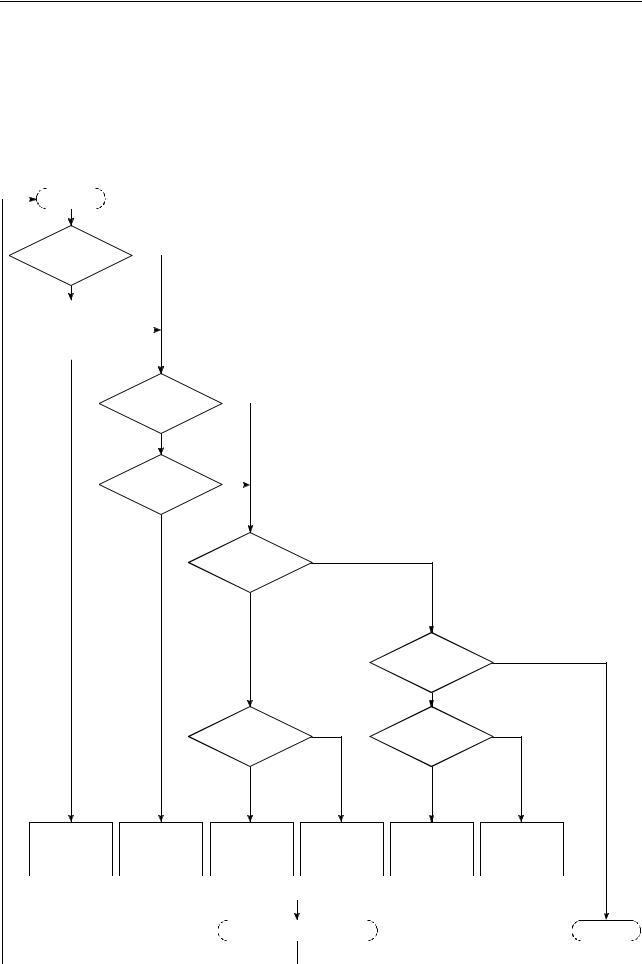
3 PALLET TRANSPORT PROCESSING
3-1 Pallet Transport Processing Flowchart
A pallet is transported to the stations according to the flowchart given below.
Once the pallet transport processing is started, the pallets are continuously transported according to the flowchart until the processing is terminated.
|
START |
|
YES |
|
|
||
A pallet in the |
|
||
|
|
||
standby station? |
|
|
|
|
NO |
|
|
An S-FIN pallet |
|
NO |
|
|
|
||
in the system? |
|
|
|
YES
A pallet in the |
|
YES |
|
|
|
||
setup station? |
|
|
|
NO |
|
|
|
A C-FIN pallet |
NO |
|
|
|
|
||
in the system? |
|
|
|
YES |
|
|
|
A C-FIN pallet |
NO |
|
|
in the standby |
|
|
|
station? |
|
|
|
YES |
|
|
|
|
|
The pallet |
NO |
|
|
in the setup station in |
|
|
|
S-FIN status? |
|
|
|
YES |
|
An empty station |
NO |
An empty station |
NO |
|
|
||
exists? |
|
exists? |
|
YES |
|
YES |
|
The S-FIN pallet is |
The C-FIN pallet |
The C-FIN pallet is |
The C-FIN pallet is |
The S-FIN pallet is |
The S-FIN pallet is |
|
unloaded from the |
unloaded from the |
unloaded from the |
unloaded from the |
|||
transported to the |
is transported to |
|||||
standby station to |
standby station to |
setup station to the |
setup station to the |
|||
standby station. |
the setup station. |
|||||
the empty station. |
the setup station. |
empty station. |
standby station. |
|||
|
|
|
|
|
|
|
|
|
|
|
|
|
|
|
|
|
|
|
|
|
|
|
|
|
|
|
|
|
Completion of Loading or Unloading |
|
|
|
|
END |
|||||||
|
|
|
|
|
|
|
|
|
|
|
|
|
|
|
|
|
|
|
|
P-5
1. The S-FIN (setup finished) pallet includes the following pallets.
NOTE
•The pallet where setup has finished.
•The pallet holding the urgent workpiece; setup has finished.
2.The C-FIN (cutting finished) pallet includes the following pallets.
•The pallet holding the workpiece which has been machined.
•The pallet holding the urgent workpiece which has been machined.
•The pallet holding the defective workpiece.

P-6
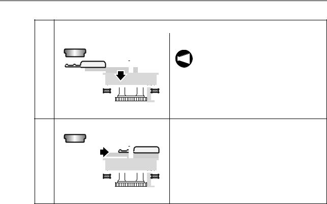
3-2 Pallet Transport Flow
The flow of pallet transport is explained.
An example of the pallet transport flow is shown below.
NOTE
No. |
|
Operation |
1 |
Setup station |
The A.G.V. moves to the setup station. |
|
Machine |
|
2 |
|
The setup station shutter is opened. |
|
|
|
|
|
|
|
|
|
|
|
Stocker |
|
|||||||
|
|
|
|
|
|
|
|
|
|
3 |
Setup station side |
The fork advances. |
|||||||
|
|
||||||||
|
|
|
|
|
|
|
|
|
|
|
|
|
|
|
|
|
|
|
|

 Rail
Rail
4 |
The fork is raised. |
When the fork holds a pallet, the A.G.V.
NOTE
leans forward.
To prevent it from leaning forward, the rail is held and supported.
The rail is supported.
5 |
|
|
|
|
|
|
|
|
|
|
|
|
The fork retracts. |
|
|
|
|
|
|
|
|
|
|
|
|
|
|
|
|
|
|
|
|
|
|
|
|
|
|
|
|
|
|
|
|
|
|
|
|
|
|
|
|
|
|
|
|
|
|
|
|
|
|
|
|
|
|
|
|
|
|
|
|
|
|
|
|
|
|
|
|
|
|
|
|
|
|
|
|
|
|
|
|
|
|
|
|
|
|
|
|
|
|
|
|
|
|
|
|
|
|
|
|
|
|
|
|
|
|
|
|
|
|
|
|
|
|
|
|
|
|
|
|
|
|
|
|
|
|

P-7
No. |
Operation |
|
6 |
The fork is lowered. |
|
|
NOTE |
The A.G.V. cannot move without |
|
releasing the rail. |
|
|
|
|
|
|
Therefore, the fork must be lowered. |
7 |
The setup station shutter is closed. |
|
8 |
The A.G.V. moves. |
|
|
• The pallet is moved while rotating 180 |
|
|
degrees. |
|
9 |
The A.G.V. stops in front of the stocker. |
|
10 |
|
|
|
|
|
|
|
The fork is raised. |
|
|
|
|
|
|
|
||
|
|
|
|
|
|
|
||
|
|
|
|
|
|
|
||
|
|
|
|
|
|
|
||
|
|
|
|
|
|
|
When the fork holds a pallet, the A.G.V.
NOTE
leans forward.
To prevent it from leaning forward, the rail is held and supported.
11 |
|
|
|
|
|
|
|
|
|
|
|
|
|
|
|
|
The fork advances. |
|
Stocker side |
||||||||||||||||
|
|
|
|
|
|
|
|
|
|
|
|
|
|
|
|
|
|
|
|
|
|
|
|
|
|
|
|
|
|
|
|
|
|
|
|
|
|
|
|
|
|
|
|
|
|
|
|
|
|
|
|
|
|
|
|
|
|
|
|
|
|
|
|
|
|
|
|
|
|
|
|
|
|
|
|
|
|
|
|
|
|
|
|
|
|
|
|
|
|
|
|
|
|
|
|
|
|
|
|
|
|
|
|
|
|
|
|
|
|
|
|
|
|
|
|
|
|
|
|
|
|
|
|
|
|
|
|
|
|
|
|
|
|
|
|
|
|
|
|
|
|
|
|
|
|
|
|
|
|
|
|
|
|
|
|
|
|
|
|
|
|
P-8
No. |
|
|
|
|
|
|
|
|
|
|
|
|
|
|
Operation |
|||
|
|
|
|
|
|
|
|
|
|
|
|
|
|
|
|
|
|
|
12 |
|
|
|
|
|
|
|
|
|
|
|
|
|
|
|
|
The fork is lowered. |
|
|
|
|
|
|
|
|
|
|
|
|
|
|
|
|
|
|
NOTE |
The A.G.V. cannot move without |
|
|
|
|
|
|
|
|
|
|
|
|
|
|
|
|
|
||
|
|
|
|
|
|
|
|
|
|
|
|
|
|
|
|
|
releasing the rail. |
|
|
|
|
|
|
|
|
|
|
|
|
|
|
|
|
|
|
|
|
|
|
|
|
|
|
|
|
|
|
|
|
|
|
|
|
|
|
Therefore, the fork must be lowered. |
|
|
|
|
|
|
|
|
|
|
|
|
|
|
|
|
|
|
|
|
|
|
|
|
|
|
|
|
|
|
|
|
|
|
|
|
|
|
|
|
|
|
|
|
|
|
|
|
|
|
|
|
|
|
|
|
|
|
|
|
|
|
|
|
|
|
|
|
|
|
|
|
|
|
|
|
|
|
|
|
|
|
|
|
|
|
|
|
|
|
|
|
|
|
|
13 |
|
|
|
|
|
|
|
|
|
|
|
|
|
|
|
The fork retracts. |
|
|
|
|
|
|
|
|
|
|
|
|
|
|
|
|
|
|
|
|
|
|
|
|
|
|
|
|
|
|
|
|
|
|
|
|
|
|
|
|
|
|
|
|
|
|
|
|
|
|
|
|
|
|
|
|
|
|
|
|
|
|
|
|
|
|
|
|
|
|
|
|
|
|
|
|
|
|
|
|
|
|
|
|
|
|
|
|
|
|
|
|
|
|
|
|
|
|
|
|
|
|
|
|
|
|
|
|
|
|
|
|
|
|
|
|
|
|
|
|
|
|
|
|
|
|
|
|
|
|
|
|
|
|
|
|
|
|
|
|
|
|
|
|
|
|
|
|
|
|
|
|
|
3-3 Urgent Workpieces (Interruption Processing)
3-3-1 Interruption Method
When the PRIORITY switch on the setup station operation panel is pressed, the "urgent request (EXPRES)" is assigned for the pallet presently located at the setup station. Once the "urgent request (EXPRES)" is assigned, the pallet is given the top priority to be transported to the machining center and after the completion of machining, it is also given the top priority to be returned to the setup station.
The "urgent request (EXPRES)" flag is cleared when the pallet is returned to the setup station again.
Setting of the "urgent request (EXPRES)" is also possible at the WORK NUMBER screen by setting the "urgent request (EXPRES)" flag at the STATUS column.
3-3-2 Interruption Operation
When the "urgent request (EXPRES)" is set, interruption operation is executed for pallet transport processing.
After the completion of presently executed pallet transport processing, pallet transport is executed for the pallet assigned the "urgent request (EXPRES)" flag. Then, upon completion of pallet transport for urgent request, the processing is continuously executed following the processing having been executed before interruption.
If the status of the pallet assigned the "urgent request (EXPRES)" is C-FIN, the pallet is transported to the setup station, and if it is S-FIN, the pallet is transported to the machining center (standby station).
P-9
4 DATA SETTING SCREENS
The data necessary for pallet pool system is set on the screens.
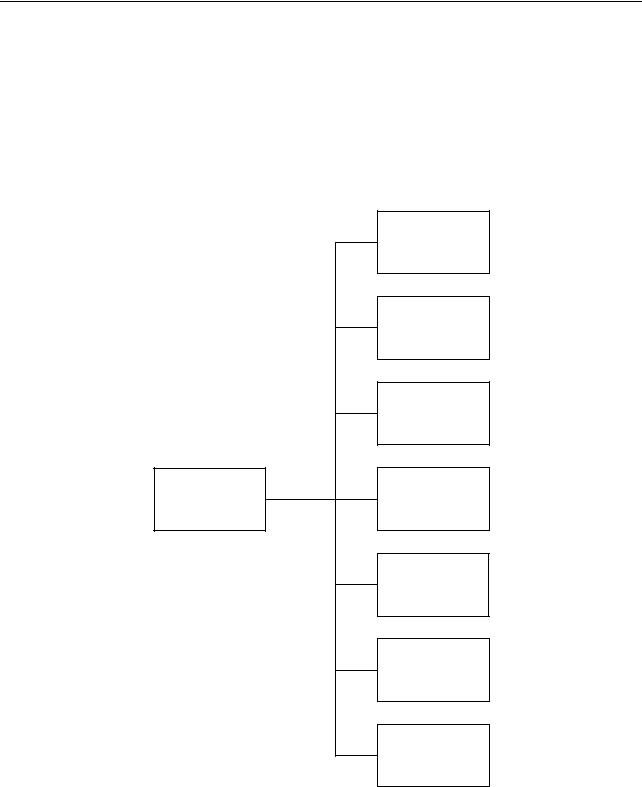
4-1 Screen Trees
<Machine side>
PCMDI MENU screen
OPERATION PANEL screen
SET-UP screen
TOOL ENTRY screen
ATC MANUAL screen
PALLET DATA screen
APC MANUAL screen
SENSOR SETTING screen

P-10
<Pallet pool side>
PCMDI MENU screen
WORK NUMBER screen
SETUP STATION PALLET CALL screen
WORK NUMBER (SUB) screen
BLOCK DELETE screen
MANUAL OPERATION screen
MANUAL OPERATION screen
A.G.V. INDEX screen
MAINTENANCE DOOR screen
ZERO RETURN OP. screen
STATUS DISPLAY screen

P-11
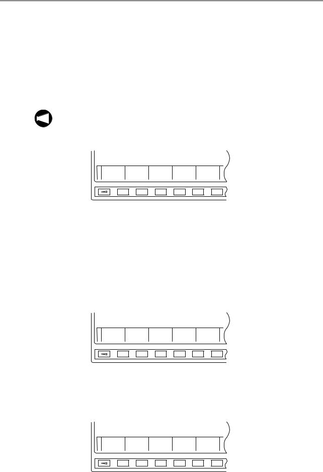
4-2 PCMDI MENU Screen
[PCMDI MENU]
1WORK NUMBER
2SETUP STATION PALLET CALL
3WORK NUMBER (SUB)
4


5MANUAL OPERATION
KEY IN NO.
NUM =
Fig. 1
Press the function selection key  (PRG-SEL/ CUSTOM) on the MDI operation panel at the pallet pool side.
This displays the PCMDI MENU screen (Fig. 1). After keying in the number of the menu item for which data should be set, press the  (INPUT) key.
The screen used for setting the selected item is displayed.
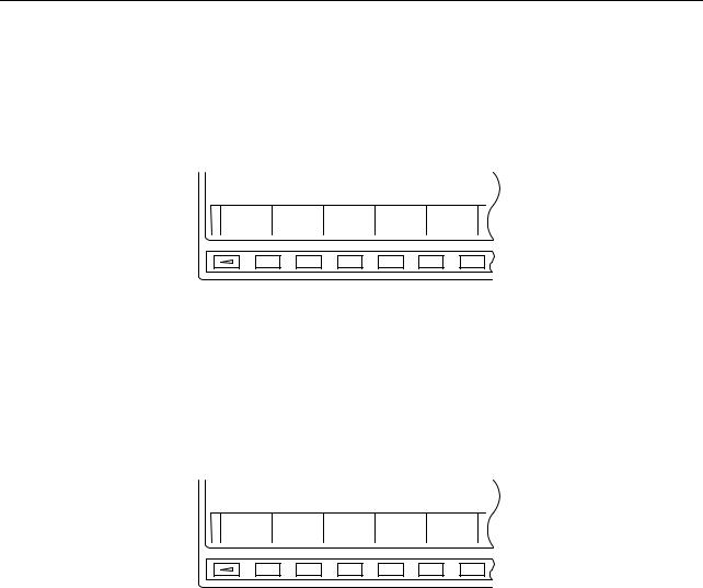
4-3 WORK NUMBER Screen
On this screen, the following information is checked, registered, or changed for each pallet.
Order of machining, setup order, pallet number, station (stocker) number, program number, and pallet status
[WORK NUMBER] ACT_No. M: 06 W: 05 |
|
||||
No. |
<PLT> |
<ST> |
<WORK> |
<STATUS> |
<SUB> |
1 |
01 |
12 |
1001 |
CUTING |
EXPRES |
2 |
02 |
31 |
1002 |
C-FIN |
|
3 |
03 |
32 |
1003 |
S-FIN |
|
4 |
04 |
1 |
1004 |
SETING |
|
5 |
05 |
33 |
1005 |
S-FIN |
EXPRES |
6 |
06 |
11 |
1006 |
S-FIN |
ST-HD |
NUM =
On the PCMDI MENU screen (Fig. 1), press the following keys in order:

 (INPUT)
The WORK NUMBER screen is displayed.
Fig. 2
P-12
<Description of the soft-keys>
[EXIT]
When this soft-key is pressed, the screen returns to the PCMDI MENU screen.
[CLEAR]
This soft-key can clear either the machining priority data or all data.
When the [CLEAR] soft-key is pressed, the soft-keys shown in Fig. 3-1 are displayed for the selection of type of data to be cleared. Upon selection of the type of data to be cleared, the soft-keys shown in Fig. 3-2 or Fig. 3-3 are displayed; pressing the [YES] soft-key clears the selected data. Press the [NO] soft-key when the data should not be cleared.
SELECT TO KIND OF DATA
CUT-NO ALLCLR CANCEL
Fig. 3-1 Soft-keys for Data Clear Operation 1
CUTTING NUMBER CLEAR OK? (YES/NO)
YES NO
Fig. 3-2 Soft-keys for Data Clear Operation 2
WORK DATA ALL CLEAR OK? (YES/NO)
YES NO
Fig. 3-3 Soft-keys for Data Clear Operation 3
P-13
[ACT_NO]
By pressing this soft-key, it is possible to change the data of "M:  " (machining priority number) and "W: ××" (setup priority number) of ACT_NO.
When the [ACT_NO] soft-key is pressed at the WORK NUMBER screen (Fig. 2), the soft-keys shown in Fig. 4 are displayed. Key in the "M:  " or "W: ××" number to be changed and press
the corresponding soft-key ([M/C] soft-key for changing the machining priority number "M:  " and [WSS] soft-key for changing the setup priority number "W: ××"). If the priority number is not changed, press the [CANCEL] soft-key.
When changing the number, it is not allowed to input a number greater than the registered
NOTE
maximum machining priority number.
When the power is turned off, both "M:  " and "W: ××" are reset to "0".
M/C WSS CANCEL
Fig. 4 Priority Number Setting Soft-keys
[SET]
This soft-key is used to change the <STATUS> (pallet status) or <SUB> (pallet sub status) data.
Pallet transport destination (machining center, setup station, stocker) is determined according to the pallet status and the pallet sub status. The pallet transport processing for the pallet and pallet sub statuses is described later.
On the WORK NUMBER screen (Fig. 2), press the [SET] soft-key after moving the cursor to the <STATUS> item, and the soft-keys shown in Fig. 5 are displayed.
S-FIN |
C-FIN SETING CUTING CLEAR |
Fig. 5 Pallet Status Setting Soft-keys
On the WORK NUMBER screen (Fig. 2), press the [SET] soft-key after moving the cursor to the <SUB> item, and the soft-keys shown in Fig. 6 are displayed.
EXPRES CUT-HD |
CLEAR |
Fig. 6 Pallet Sub Status Setting Soft-keys
P-14
[N-SORT]
When this soft-key is pressed while the data is shown at random in terms of machining priority numbers, the data is arranged in the ascending order of machining priority numbers.
The soft-keys shown in Fig. 7 are displayed when the continuous menu key [+] is pressed on the WORK NUMBER screen (Fig. 2).
N-SORT CHANGE
Fig. 7 [N-SORT] and [CHANGE] Soft-keys
[CHANGE]
By using this soft-key, it is possible to change the machining reserved status pallets (CUT-HD) to the S-FIN status pallets in batch.
When the [CHANGE] soft-key is pressed, the soft-keys shown in Fig. 8 are displayed. Press the [YES] soft-key to execute global change. To cancel the operation, press the [NO] soft-key.
DATA CHANGE OK?
YES NO
Fig. 8 Change Function Soft-keys
P-15
<Details of the items>
<ACT_NO M:  W: ××>
<M:  >
>
The machining priority number of the pallet which is or which has been at the standby station.
Transport of the S-FIN pallets to the standby station (machine) is controlled based on this number.
For the procedure used for changing this number, refer to <Description of the soft-keys> on page P-12.
<Example: M: 04>
The system executes "search" for the S-FIN status pallets in the ascending order of the machining priority numbers beginning with "5". If a S-FIN pallet is found, that pallet is transported to the standby station. As soon as the pallet transport begins, the data for ACT_NO is updated to "M: 06", for example if the machining priority number of the transported pallet is "6".
If no S-FIN status pallet is found when search is made up to the pallet assigned the largest machining priority number, the search is repeated from the smallest machining priority number. If no S-FIN status pallet is found in this search, executed to the machining priority number of "3", pallet transport processing is not executed.
The ACT_NO data is not changed if interruption processing for the urgent request is being
NOTE
executed.
<W: ××>
The setup priority number of the pallet which is or which has been at the setup station.
Transport of such a pallet as the C-FIN status pallet and NG status pallet to the setup station is controlled based on this number.
For the procedure used for changing this number, refer to <Description of the soft-keys> on page P-12.
<Example: W: 04>
The system executes "search" for the pallets such as C-FIN status pallets which should be transported to the setup station in the ascending order of the machining priority numbers beginning with "5". If such a pallet is found, that pallet is transported to the standby station. As soon as the pallet transport begins, the data for ACT_NO is updated to "W: 06", for example if the machining priority number of the transported pallet is "6".
If C-FIN status pallet or pallets in the status to be transported to the setup station are not found when search is made up to the pallet assigned the largest machining priority number, the search is repeated from the smallest machining priority number. If no pallet to be transported to the setup station is found in this search which is executed to the machining priority number of "3", pallet transport processing is not executed.
The ACT_NO data is not changed if interruption processing for the urgent request is being
NOTE
executed.

P-16
<NO.>
Displays the machining priority number.
•Setting is possible in the range from 0 to 99.
•The machining priority number must be unique and it is not allowed to set the same number for more than one pallet.
<PLT>
Displays the pallet number.
•Setting is possible in the range from 0 to 99.
•The pallet number must be unique and it is not allowed to set the same number for more than one pallet.
<ST>
Displays the station number of the station where the pallet is stored.
•The station number must be unique and it is not allowed to set the same number for more than one pallet.
•The number assigned to an empty station cannot be used.
•Setting should be made using the following numbers:
1: Setup station
11:Standby station
12:In-machine station
31:Stocker number 31
32:Stocker number 32
<WORK>
Displays the program number corresponding to the individual pallets <PLT>.
•This number indicates a program number of the program used for machining the workpiece(s) mounted on the pallet. Setting is possible with up to a four-digit number.
<STATUS>
Displays the status of the individual pallets.
•To change the present setting for <STATUS>, move the cursor to the <STATUS> column and press the [SET] soft-key, then the status setting soft-keys are displayed. Press the required one for changing the status.
•When changing the <STATUS> data, entry of a pallet status is not possible unless the station number is set for the pallet for which the status should be changed.
•The following four status items are provided: S-FIN, C-FIN, CUTING, and SETING
•For the display of <STATUS> items for the individual pallet statuses, refer to Table 1.
Loading...