


 Loading...
Morii-Seiiki MSX-850, MSX-850III, MSX-501, MSX-501III, MSX-502 Instruction Manual
...MORI-SERVER
INSTRUCTION MANUAL
Applicable Model
MORI-SERVER Specification
Applicable NC Unit
MSX-850 MSX-501 MSX-502 MSX-511 MSG-803 MSG-805 MSG-806
MSX-850III MSX-501III MSX-502III MSX-511III MSG-500 MSG-501 MSG-502
Before starting operation, maintenance, or programming, carefully read the manuals supplied by Mori Seiki, the NC unit manufacturer, and equipment manufacturers so that you fully understand the information they contain.
Keep the manuals carefully so that they will not be lost.
IM-MORISERVER-A1E

•The contents of this manual are subject to change without notice due to improvements to the machine or in order to improve the manual. Consequently, please bear in mind that there may be slight discrepancies between the contents of the manual and the actual machine. Changes to the instruction manual are made in revised editions which are distinguished from each other by updating the instruction manual number.
•Should you discover any discrepancies between the contents of the manual and the actual machine, or if any part of the manual is unclear, please contact Mori Seiki and clarify these points before using the machine. Mori Seiki will not be liable for any damages occurring as a direct or indirect consequence of using the machine without clarifying these points.
•All rights reserved: reproduction of this instruction manual in any form, in whole or in part, is not permitted without the written consent of Mori Seiki.
The product shipped to you (the machine and accessory equipment) has been manufactured in accordance with the laws and standards that prevail in the relevant country or region. Consequently it cannot be exported, sold, or relocated, to a destination in a country with different laws or standards.
The export of this product is subject to an authorization from the government of the exporting country.
Check with the government agency for authorization.
990730

NOTICE
•The copying, reproduction, or retransmission of any part or all of this manual without the prior consent in writing of Mori Seiki Co., Ltd. is expressly forbidden.
•Product specifications and information contained in this manual are subject to change without notification.
•Mori Seiki can take no responsibility for anything caused by the operation of this product and this manual, or for anything caused as a result of such operation.
•The copyright for this product is held by Mori Seiki Co., Ltd.
•This product may be used only by persons specified in the contract as authorized to use the software.
Registered Trademark
•Microsoft, Windows, Windows NT, Windows 2000, Windows XP and Internet Explorer are registered trademarks of Microsoft Corporation in the United States and in other countries.
•Microsoft product screen shot(s) are reprinted with permission from Microsoft Corporation.
•Other company names and product names are trademarks or registered trademarks of the individual companies.
Data which has been input or generated by this software can be rendered unusable due to hard disk failure.
Any important data you have input or created should always be saved on a floppy disk or on an appropriate storage medium to avoid loss of data.
CONTENTS
SIGNAL WORD DEFINITION
PREFACE
A:MORI-SERVER
B:MORI-SERVER (DSN)
C:TROUBLESHOOTING INDEX
SIGNAL WORD DEFINITION
A variety of symbols are used to indicate different types of warning information and advice.
Learn the meanings of these symbols and carefully read the explanation to ensure safe operation while using this manual.
<Symbols related with warning>
The warning information is classified into three categories, DANGER, WARNING, and CAUTION. The following symbols are used to indicate the level of danger.
DANGER Indicates an imminently hazardous situation which, if not avoided, will result in death or serious injury.
The information described in the DANGER frame must be strictly observed.
WARNING Indicates a potentially hazardous situation which, if not avoided, could result in death or serious injury.
The information described in the WARNING frame must be strictly observed.
CAUTION Indicates a potentially hazardous situation which, if not avoided, may result in minor or
moderate injury or damages to the machine.
The information described following the caution symbol must be strictly observed.
<Other symbols>
Indicates the items that must be taken into consideration.
NOTE
Indicates useful guidance relating to operations.
Indicates the page number or manual to be referred to.
The number in ( ) indicates the section number.
PREFACE
This manual gives you the information you need to operate the MORI-SERVER or MORISERVER (DSN) software. The information explained in each chapter is briefly described below.
A:MORI-SERVER
This chapter describes the procedure for setups, settings and operations of the MORISERVER.
B:MORI-SERVER (DSN)
This chapter describes the procedure for setups, settings and operations of the MORISERVER (DSN).
C:TROUBLESHOOTING
This chapter describes the points to be checked before making an inquiry if you have failed in telecommunications with the MORI-SERVER or MORI-SERVER (DSN).

CHAPTER A
MORI-SERVER
This chapter describes the procedure for setups, settings and operations of the MORISERVER.

CONTENTS
A : MORI-SERVER
1 SETUP. . . . . . . . . . . . . . . . . . . . . . . . . . . . . . . . . . . . . . . . . . . . . . . . . . . . . . . . . . . . . . . A-1
1-1 Installation . . . . . . . . . . . . . . . . . . . . . . . . . . . . . . . . . . . . . . . . . . . . . . . . . . . . . . . A-1
1-1-1 Operating Environment . . . . . . . . . . . . . . . . . . . . . . . . . . . . . . . . . . . . . . A-1
1-1-2 Installing the MORI-SERVER (PC Operation) Software . . . . . . . . . . . . . A-2
1-1-3 Initial Setting of the Communication Module . . . . . . . . . . . . . . . . . . . . . . A-5
1-1-3-1 Starting the MORI-SERVER Utility . . . . . . . . . . . . . . . . . . . . . A-5
1-1-3-2 Setting Communications Parameters . . . . . . . . . . . . . . . . . . . A-6
1-1-3-3 Log Output Setting. . . . . . . . . . . . . . . . . . . . . . . . . . . . . . . . . . A-8
1-1-3-4 Setting the Data Format. . . . . . . . . . . . . . . . . . . . . . . . . . . . . A-10
1-2 Settings . . . . . . . . . . . . . . . . . . . . . . . . . . . . . . . . . . . . . . . . . . . . . . . . . . . . . . . . A-12
1-2-1 Language Setting. . . . . . . . . . . . . . . . . . . . . . . . . . . . . . . . . . . . . . . . . . A-12
1-2-2 NC Program Data Size Display Unit Setting . . . . . . . . . . . . . . . . . . . . . A-14
1-2-3 Default Input/Output Folder Setting . . . . . . . . . . . . . . . . . . . . . . . . . . . . A-15
1-2-4 Machine Information Setting . . . . . . . . . . . . . . . . . . . . . . . . . . . . . . . . . A-17
1-2-4-1 New Machine Registration. . . . . . . . . . . . . . . . . . . . . . . . . . . A-18
1-2-4-2 Modifying Machine Information . . . . . . . . . . . . . . . . . . . . . . . A-21
1-2-4-3 Deleting Machine Information . . . . . . . . . . . . . . . . . . . . . . . . A-24
1-2-5 Default File Name Setting . . . . . . . . . . . . . . . . . . . . . . . . . . . . . . . . . . . A-25
1-2-5-1 Default File Name Format Setting . . . . . . . . . . . . . . . . . . . . . A-26
1-2-5-2 Default Extension Function . . . . . . . . . . . . . . . . . . . . . . . . . . A-32
1-3 Settings at MAPPS . . . . . . . . . . . . . . . . . . . . . . . . . . . . . . . . . . . . . . . . . . . . . . . A-33
1-3-1 Setting TCP/IP Parameters . . . . . . . . . . . . . . . . . . . . . . . . . . . . . . . . . . A-33
1-3-2 MORI-SERVER PARAMETER Screen . . . . . . . . . . . . . . . . . . . . . . . . . A-34
1-3-3 Setting MORI-SERVER Parameters . . . . . . . . . . . . . . . . . . . . . . . . . . . A-38
1-4 Settings at MAPPS II/III. . . . . . . . . . . . . . . . . . . . . . . . . . . . . . . . . . . . . . . . . . . . A-41
1-4-1 Setting TCP/IP Parameters . . . . . . . . . . . . . . . . . . . . . . . . . . . . . . . . . . A-41
1-4-1-1 How to Display the Setting Screen . . . . . . . . . . . . . . . . . . . . A-41
1-4-1-2 Basic Network Setting . . . . . . . . . . . . . . . . . . . . . . . . . . . . . . A-44
1-4-2 MORI-SERVER PARAMETER Screen . . . . . . . . . . . . . . . . . . . . . . . . . A-47

1-4-3 MORI-SERVER FUNCTION BASIC SETTING Screen . . . . . . . . . . . . . A-49
1-4-4 MORI-SERVER DETAIL SETTING Screen . . . . . . . . . . . . . . . . . . . . . . A-55
2 COMMUNICATION FUNCTIONS . . . . . . . . . . . . . . . . . . . . . . . . . . . . . . . . . . . . . . . . . A-59
2-1 Selecting the Communication Target Machine . . . . . . . . . . . . . . . . . . . . . . . . . . A-59 2-1-1 Selection from the List of Registered Machines. . . . . . . . . . . . . . . . . . . A-59 2-1-2 Manual Selection . . . . . . . . . . . . . . . . . . . . . . . . . . . . . . . . . . . . . . . . . . A-61 2-2 Communications Operations . . . . . . . . . . . . . . . . . . . . . . . . . . . . . . . . . . . . . . . . A-63 2-2-1 Message Transmit Function. . . . . . . . . . . . . . . . . . . . . . . . . . . . . . . . . . A-63 2-2-2 NC Program List Obtaining Function . . . . . . . . . . . . . . . . . . . . . . . . . . . A-65 2-2-3 Individual NC Program Output Function . . . . . . . . . . . . . . . . . . . . . . . . A-68 2-2-4 Individual NC Program Input Function . . . . . . . . . . . . . . . . . . . . . . . . . . A-73 2-2-5 NC Program Delete Function. . . . . . . . . . . . . . . . . . . . . . . . . . . . . . . . . A-77 2-2-6 All NC Program Output Function . . . . . . . . . . . . . . . . . . . . . . . . . . . . . . A-81 2-2-7 All NC Program Input Function . . . . . . . . . . . . . . . . . . . . . . . . . . . . . . . A-85 2-2-8 Conversational Program List Obtaining Function. . . . . . . . . . . . . . . . . . A-89 2-2-9 Conversational Program Output Function . . . . . . . . . . . . . . . . . . . . . . . A-91 2-2-10 Conversational Program Input Function . . . . . . . . . . . . . . . . . . . . . . . . A-96 2-2-11 Conversational Program Delete Function . . . . . . . . . . . . . . . . . . . . . . . A-99 2-2-12 Tool File Output Function . . . . . . . . . . . . . . . . . . . . . . . . . . . . . . . . . . . A-104 2-2-13 Tool File Input Function . . . . . . . . . . . . . . . . . . . . . . . . . . . . . . . . . . . . A-108 2-2-14 Card DNC Area List Obtaining Function . . . . . . . . . . . . . . . . . . . . . . . A-112 2-2-15 Card DNC Area Communication Target Folder Move Function . . . . . . A-114 2-2-16 Card DNC Folder Create Function. . . . . . . . . . . . . . . . . . . . . . . . . . . . A-117 2-2-17 Card DNC Area File/Folder Output Function . . . . . . . . . . . . . . . . . . . . A-119 2-2-18 Card DNC Area File Input Function . . . . . . . . . . . . . . . . . . . . . . . . . . . A-123 2-2-19 Card DNC Area File/Folder Delete Function . . . . . . . . . . . . . . . . . . . . A-127
2-3 Communication Interlocks . . . . . . . . . . . . . . . . . . . . . . . . . . . . . . . . . . . . . . . . . A-131
2-3-1 Common Interlock Options . . . . . . . . . . . . . . . . . . . . . . . . . . . . . . . . . A-131
2-3-1-1 Main Function OFF . . . . . . . . . . . . . . . . . . . . . . . . . . . . . . . A-131
2-3-1-2 IP Address Verification. . . . . . . . . . . . . . . . . . . . . . . . . . . . . A-131
2-3-1-3 User Verification. . . . . . . . . . . . . . . . . . . . . . . . . . . . . . . . . . A-131

2-3-1-4 Communications with MORI-SERVER in Progress . . . . . . . A-131 2-3-1-5 MAPPS Input/Output in Progress . . . . . . . . . . . . . . . . . . . . A-131 2-3-1-6 System Screen Displayed . . . . . . . . . . . . . . . . . . . . . . . . . . A-131 2-3-1-7 Exclusive Control Function . . . . . . . . . . . . . . . . . . . . . . . . . A-132 2-3-2 Restrictions on Individual Functions . . . . . . . . . . . . . . . . . . . . . . . . . . A-132 2-3-2-1 Message Transmit Function . . . . . . . . . . . . . . . . . . . . . . . . A-132 2-3-2-2 NC Program List Obtaining Function . . . . . . . . . . . . . . . . . . A-132 2-3-2-3 Individual NC Program Output Function . . . . . . . . . . . . . . . A-132 2-3-2-4 Individual NC Program Input Function. . . . . . . . . . . . . . . . . A-132 2-3-2-5 NC Program Delete Function. . . . . . . . . . . . . . . . . . . . . . . . A-133 2-3-2-6 All NC Program Output Function . . . . . . . . . . . . . . . . . . . . . A-133 2-3-2-7 All NC Program Input Function . . . . . . . . . . . . . . . . . . . . . . A-133 2-3-2-8 Conversational Program List Obtaining Function . . . . . . . . A-133 2-3-2-9 Conversational Program Output Function . . . . . . . . . . . . . . A-134 2-3-2-10 Conversational Program Input Function . . . . . . . . . . . . . . . A-134 2-3-2-11 Conversational Program Delete Function . . . . . . . . . . . . . . A-134 2-3-2-12 Conversational Parameter Output Function . . . . . . . . . . . . A-134 2-3-2-13 Conversational Parameter Input Function . . . . . . . . . . . . . . A-135 2-3-2-14 Card DNC Area List Obtaining Function . . . . . . . . . . . . . . . A-135
2-3-2-15 Card DNC Area Communication
Target Folder Move Function . . . . . . . . . . . . . . . . . . . . . . . . A-135 2-3-2-16 Card DNC Area Folder Create Function . . . . . . . . . . . . . . . A-135 2-3-2-17 Card DNC Area File/Folder Output Function . . . . . . . . . . . . A-135 2-3-2-18 Card DNC Area File Input Function . . . . . . . . . . . . . . . . . . . A-135 2-3-2-19 Card DNC Area File/Folder Delete Function . . . . . . . . . . . . A-136
2-4 MAPPS Safety Functions . . . . . . . . . . . . . . . . . . . . . . . . . . . . . . . . . . . . . . . . . A-137
2-4-1 Key Input Lock Function . . . . . . . . . . . . . . . . . . . . . . . . . . . . . . . . . . . A-137
3 MESSAGE DISPLAY FUNCTION . . . . . . . . . . . . . . . . . . . . . . . . . . . . . . . . . . . . . . . . A-138
3-1 MORI-SERVER Messages . . . . . . . . . . . . . . . . . . . . . . . . . . . . . . . . . . . . . . . . A-138
3-1-1 Communication Message . . . . . . . . . . . . . . . . . . . . . . . . . . . . . . . . . . A-139
3-1-2 Communication Completion Message . . . . . . . . . . . . . . . . . . . . . . . . . A-141
3-1-3 Error Messages . . . . . . . . . . . . . . . . . . . . . . . . . . . . . . . . . . . . . . . . . . A-141
4 ERROR MESSAGES . . . . . . . . . . . . . . . . . . . . . . . . . . . . . . . . . . . . . . . . . . . . . . . . . A-142
4-1 Error Message Display . . . . . . . . . . . . . . . . . . . . . . . . . . . . . . . . . . . . . . . . . . . A-142
4-1-1 Error Message Display Formats. . . . . . . . . . . . . . . . . . . . . . . . . . . . . . A-144
4-2 Contents of Error Messages . . . . . . . . . . . . . . . . . . . . . . . . . . . . . . . . . . . . . . . A-146
5 MESSAGES AT MAPPS . . . . . . . . . . . . . . . . . . . . . . . . . . . . . . . . . . . . . . . . . . . . . . . A-152
5-1 Display Items in a Message Box . . . . . . . . . . . . . . . . . . . . . . . . . . . . . . . . . . . . A-153
5-2 Contents of Messages. . . . . . . . . . . . . . . . . . . . . . . . . . . . . . . . . . . . . . . . . . . . A-154
6 MESSAGES AT MAPPS II/III . . . . . . . . . . . . . . . . . . . . . . . . . . . . . . . . . . . . . . . . . . . A-156
6-1 Message Screen . . . . . . . . . . . . . . . . . . . . . . . . . . . . . . . . . . . . . . . . . . . . . . . . A-156
6-2 Message Priority Levels . . . . . . . . . . . . . . . . . . . . . . . . . . . . . . . . . . . . . . . . . . A-157
6-3 Message Meanings . . . . . . . . . . . . . . . . . . . . . . . . . . . . . . . . . . . . . . . . . . . . . . A-158
6-4 Refresh of "Highest" Priority Level Messages. . . . . . . . . . . . . . . . . . . . . . . . . . A-167
6-5 Clearing Messages . . . . . . . . . . . . . . . . . . . . . . . . . . . . . . . . . . . . . . . . . . . . . . A-169

MORI-SERVER A-1
1 SETUP
The method for installing MORI-SERVER is described below.
1-1 Installation
1-1-1 Operating Environment
The following operating environment is required to operate the MORI-SERVER.
Hardware and Software |
Requirements |
|
|
|
|
|
• Windows NT Workstation (Service Pack 6 or above) |
|
|
• Windows NT Server (Service Pack 6 or above) |
|
OS |
• Windows 2000 Professional (Service Pack 3 or above) |
|
• Windows 2000 Server (Service Pack 3 or above) |
||
|
||
|
• Windows XP Professional |
|
|
<Any operating system from the above> |
|
|
|
|
CPU |
Pentium III 500 MHz or faster processor |
|
|
|
|
Memory |
64 MB or more |
|
|
|
|
Network |
10BASE-T/100BASE-TX Ethernet |
|
|
|
|
Monitor |
XGA or above |
|
|
|
A-2 MORI-SERVER
1-1-2 Installing the MORI-SERVER (PC Operation) Software
Install the MORI-SERVER software for operations from a PC as follows.
When installing the MORI-SERVER software, log on to the Windows with an account that
NOTE
has administrator privileges.
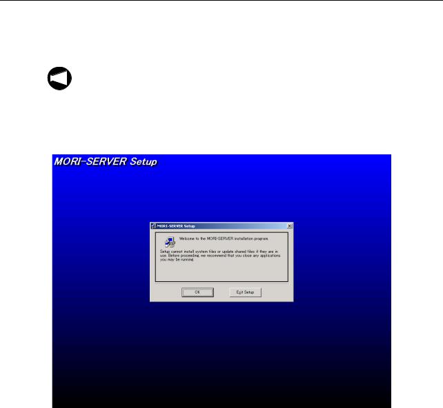
1)Run "Setup.exe" in the "\MORI-SERVER\ENGLISH" folder.
"MORI-SERVER Setup" will start and the screen will appear as shown in Fig. A-1.
2)Click the [OK] button.
Fig. A-1
MORI-SERVER A-3
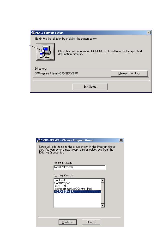
The setup start confirmation dialog box will be displayed (Fig. A-2).
3)Confirm the directory where the software is to be installed, with is displayed at "Directory". To change the installation destination, click the [Change Directory] button.
Setup start button
Fig. A-2
4)After confirming the directory where the software is to be installed, click the setup start button, Fig. A-2.
The "Choose Program Group" dialog box is displayed, as indicated in Fig. A-3.
5)Select "MORI-SERVER" and click the [Continue] button. Installation will start.
Fig. A-3

A-4 MORI-SERVER
When the setup completed message (Fig. A-4) is displayed, installation is completed.
Fig. A-4
MORI-SERVER A-5
1-1-3 Initial Setting of the Communication Module
You need to complete initial setting of the communication module before using MORI-SERVER. There are two components to this: 1. Setting the communication parameters, 2. Setting log output. Make these settings by following the procedure below.
1-1-3-1 Starting the MORI-SERVER Utility
To perform initial setting of the communication module, first start the MORI-SERVER utility, then make the individual settings.
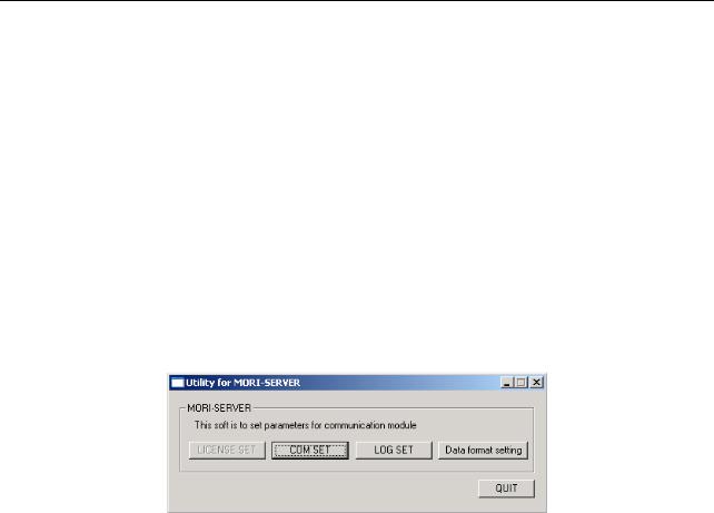
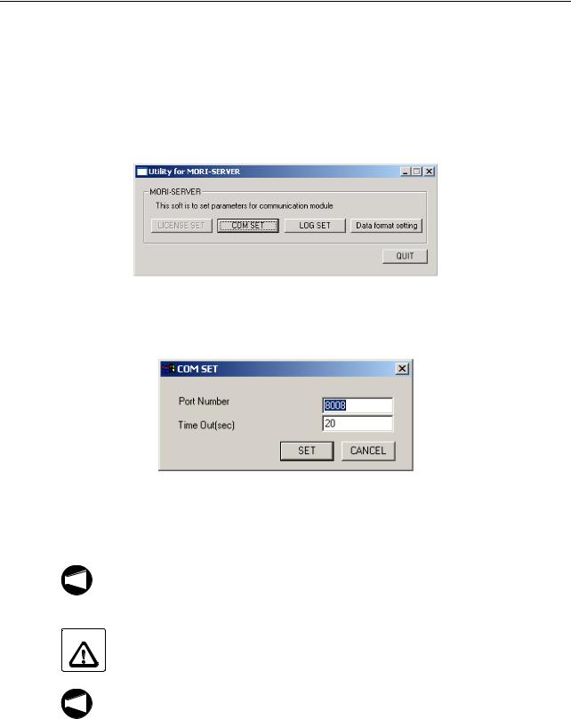
1)Select "Programs" - "MORI-SERVER" - "REGTOOL" from the Start menu. The MORI-SERVER utility will start as shown in Fig. A-5.
2)To set the communications parameters, click the [COM SET] button. To set log output click the [LOG SET] button. To set the data format click the [Data format setting] button. The appropriate setting screen will open in each case.
Fig. A-5
3)To quit the MORI-SERVER utility, click the [QUIT] button or the  button at the top right of the "Utility for MORI-SERVER" window.
A-6 MORI-SERVER
1-1-3-2 Setting Communications Parameters
This section explains how to make the settings relating to MORI-SERVER communications (port number and so on).
1)Start MORI-SERVER utilities by following the procedure in 1-1-3-1 "Starting the MORI-SERVER Utility" (page A-5), then click the [COM SET] button in the "Utility for MORI-SERVER" dialog box.
Fig. A-6
The "COM SET" dialog box (Fig. A-7), will be displayed.
Fig. A-7
2)Enter the port number to be used for communications in the "Port Number" textbox (Fig. A-7).
1. This parameter setting can only be changed by users with Administrator rights.
NOTE
2.Normally, the default setting "8008" is used. Change the setting of this parameter only when the "8008" port is used by other software.
CAUTION This parameter setting should only be changed by a person with a good knowledge of
the network. If the number of a port that is being used by other software is specified, it may cause problems with the software using that port.
If you change this parameter setting, you must also set the same value for the MAPPS
NOTE
port number set in 1-4-3 "MORI-SERVER FUNCTION BASIC SETTING Screen" (page A-49). If different port numbers are set for MORI-SERVER and MAPPS, communications cannot be established.

MORI-SERVER A-7
3)Set the time period before a time-out error occurs in the "Time Out (sec)" textbox (Fig. A-7).
NOTE
1. If the time set for this parameter is too short, time out may occur if processing takes some time, so make the setting 20 seconds or longer.
2.The actual time that causes a timeout error may differ from the time period set here.
4)When you have finished communications parameter entry, click the [SET] button (see Fig. A-7) to set your entries.
The settings made for the communications parameters will be confirmed and the "COM SET" dialog box will close.
To cancel the setting of the communications parameters, click the [CANCEL] button.
A-8 MORI-SERVER
1-1-3-3 Log Output Setting
This section explains the settings for the logs to be output when communications are conducted with MORI-SERVER.
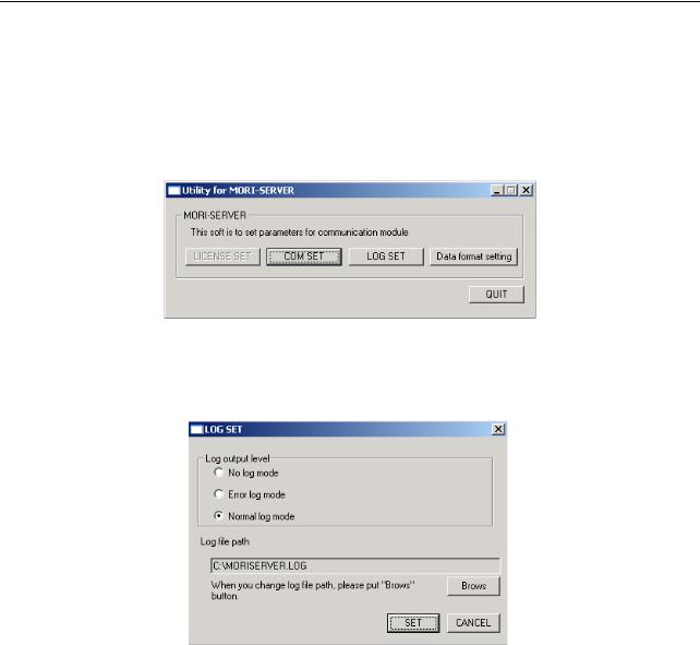
1)Start the MORI-SERVER utility as described in 1-1-3-1 "Starting the MORI-SERVER Utility" (page A-5), then click the [LOG SET] button in the "Utility for MORI-SERVER" dialog box.
Fig. A-8
The "LOG SET" dialog box, shown in Fig. A-9, will be displayed.
Fig. A-9
2)For the "Log output level" in this dialog box, select one of the following three output modes: "No log mode", "Error log mode", or "Normal log mode".
<Log output mode>
•No log mode No log is output.
•Error log mode
Logs are output only when an error occurs in communication.
•Normal log mode
Logs are output when an error occurs in communication or when communication is successfully completed.
MORI-SERVER A-9
3)Check if a file appropriate as the log output destination is displayed in the "Log file path" area.
If there is no problem, proceed to step 4) below.
To change the log output destination file, follow the procedure below.
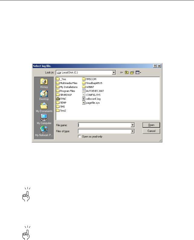
a)Click the [Brows] button in the "LOG SET" dialog box (Fig. A-9).
The "Select log file." dialog box, shown in Fig. A-10, will be displayed.
b)Select the folder to serve as the log output destination.
Fig. A-10
c)Select the file to which logs are to be output.
To create a new file, enter the name of the file in the "File name" textbox.
d)After selecting the file to which logs are to be output or entering its filename, click the [Open] button (Fig. A-10).
To cancel the change in log output destination, click the [Cancel] button.
The "Select log file." dialog box will close and the full path to the filename selected for the "Log file path" in the "LOG SET" dialog box (Fig. A-9) will be displayed.
4)When you have selected the log output level and the log output file, click the [SET] button in the "LOG SET" dialog box (Fig. A-9) to confirm the settings.
To cancel the log output setting, click the [CANCEL] button.
A-10 MORI-SERVER
1-1-3-4 Setting the Data Format
This section explains how to make the settings for two functions that operate during communications using MORI-SERVER: conversion of carriage return codes on program output and addition of the %LF code to the head of data being input.
1)Start the MORI-SERVER utility as described in 1-1-3-1 "Starting the MORI-SERVER Utility" (page A-5), then click the [Data format setting] button shown in Fig. A-11.
Fig. A-11
The "Data Format Set" dialog box, shown in Fig. A-12, will be displayed.
Fig. A-12
2)Use the "Supplement \%LF" radio button in the "Data Format Set" dialog box (Fig. A-12) to select whether the function for adding the %LF code at the head of a file for input, if there is no such code already, is on or off.
An initial %LF code is required in program files that are input into MAPPS. If the "Valid" option is selected for this function, when an attempt is made to input a file that starts with a 0 number and has no initial %LF code, a %LF code is added so that the file can be input in the required format for communications.
3)Use the "Translate LF-CRLF" radio button (Fig. A-12) to select whether the function that converts the carriage return code LF to CRLF before the data is output is on or off.
When a program is output from MAPPS, the EOB (;) code in the program is output as LF. When this function is "Valid", these LF codes are converted to CRLF codes before output, so when a program is opened using NotePad for example, it is displayed with the correct line breaks.

MORI-SERVER A-11
4)After making the data format settings, click the [SET] button to confirm them (Fig. A-12). The data format will be set and the "Date Format Set" dialog box will close.
To cancel your data format settings, click the [CANCEL] button.
A-12 MORI-SERVER
1-2 Settings
1-2-1 Language Setting
MORI-SERVER is compatible with a multi-language display function and its display language can be displayed easily.
This section explains the procedure for changing the display language.
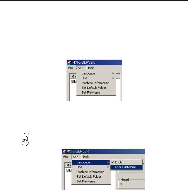
1)Select the "Language" option from the "Set" menu, as shown in Fig. A-13.
Fig. A-13
The list of registered languages is displayed (Fig. A-14).
2)Select the language you want to use by clicking on it.
A check mark is displayed next to the language that is currently selected.
Fig. A-14
MORI-SERVER A-13
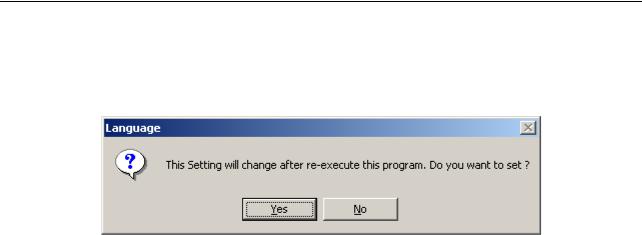
The language change confirmation message (Fig. A-15) will be displayed.
3)To change the display language, click [Yes] button. To cancel the change of display language, click [No] button.
Fig. A-15
4)Clicking the [Yes] button closes MORI-SERVER. Restart MORI-SERVER.
The change made to the display language takes effect after restarting MORI-SERVER.

A-14 MORI-SERVER
1-2-2 NC Program Data Size Display Unit Setting
MORI-SERVER allows selection of the unit to be used to display the data size of NC programs in the list of NC programs obtained from the communication target machine: the selection is "byte" or "m". This section explains the procedure for setting this display unit.
1)Select the "Unit" submenu from the "Set" menu (Fig. A-16).
Fig. A-16
The display changes as shown in Fig. A-17.
2)Select the unit to be used by clicking it.
A checkmark is displayed next to the unit that is currently selected.
Fig. A-17
This changes the display unit for the data size of NC programs.
The change applies immediately so it is not necessary to restart MORI-SERVER.

MORI-SERVER A-15
1-2-3 Default Input/Output Folder Setting
MORI-SERVER enables input/output of NC programs between a machine and a personal computer. This section explains the procedure for setting a folder in a personal computer as the default folder for NC program input/out operations when MORI-SERVER starts.
Input and output folder selection area
Fig. A-18
1)From the folder tree in the input and output folder selection area (Fig. A-19), select the folder to be set as the default input/output destination.
Fig. A-19

A-16 MORI-SERVER
2)Select the "Set Default Folder" option in the "Set" menu (Fig. A-20).
Fig. A-20
This completes setting of the default input and output destination folder.
From the next start of MORI-SERVER, the default input/output folder set here will be selected as the default folder.

MORI-SERVER A-17
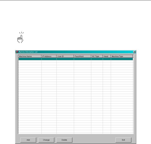
1-2-4 Machine Information Setting
MORI-SERVER allows you to pre-register the machine information of up to 50 machines that will be used as communication targets. To register, modify or delete machine information, you must first display the Machine Information List window as shown below.
For details on the procedures for registration, modification and deletion, refer to the later sections on these operations.
1)Select "Machine Information" from the "Set" menu as shown in Fig. A-21.
Fig. A-21
The "Machine Information List" window, shown in Fig. A-22, will be displayed.
Fig. A-22
2)Carry out the registration, modification or deletion operations (described here) as required.
3)To close the "Machine Information List" window, click either the [Exit] button at the bottom right of the window or the close button  at the top right.
A-18 MORI-SERVER
1-2-4-1 New Machine Registration
To make a new machine registration, proceed as follows.
1)In the "Machine Information List" window (Fig. A-23), select the position where the newly-registered machine information is to be inserted, then click the [Add] button.
The order of the machines in the registered machine list on the MORI-SERVER main screen follows the order of registration in this "Machine Information List" window, so you must consider the display order in the registered machine list when making registrations.
Fig. A-23
MORI-SERVER A-19
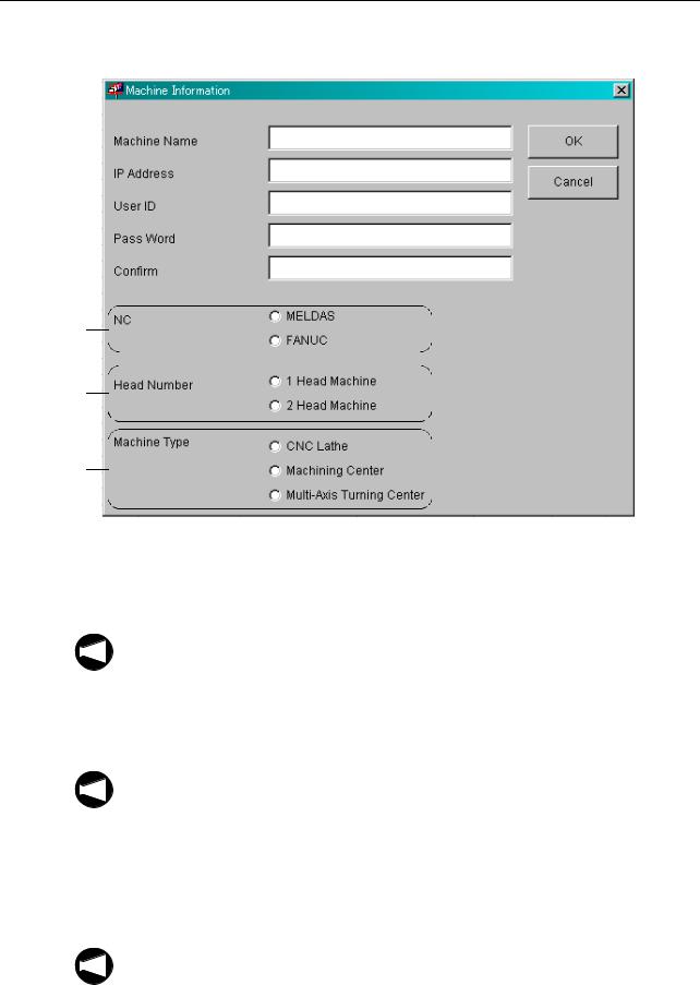
The "Machine Information" dialog box, shown in Fig. A-24, opens.
(1)
(2)
(3)
(4)
(5)
(6)
(7)
(8)
Fig. A-24
2)Enter the name that will identify the machine being registered in the "Machine Name" textbox (1).
1. You can enter up to 64 characters for the machine name.
NOTE
2. You cannot register a machine name that has been used before.
3) Enter the IP address of the machine being registered in the "IP Address" textbox (2).
4) Enter the user ID, registered at the machine being registered to identify that machine, in the "User ID" textbox (3).
NOTE
1. If user verification is disabled on the machine being registered, there is no need to make an entry here.
2. Due to restrictions at the machine on characters that can be registered, only upper case characters can be used in user IDs. If a user ID is entered in lower case letters, they are converted to upper case before registration.
5) Enter the password associated with the user ID just entered in the "Pass Word" textbox (4). The entered password is displayed as asterisks.
NOTE
1. As with the user ID, if user verification is disabled on the machine being registered, you need not make an entry here.
2.Only one-byte upper case characters can be used to register a password. Passwords containing other types of character are inadmissible.
Loading...