


MORI-SERVER
INSTRUCTION MANUAL
Applicable Model
MORI-SERVER Specification
Applicable NC Unit
MSX-850 MSX-850III
MSX-501 MSX-501III
MSX-502 MSX-502III
MSX-511 MSX-511III
MSG-803 MSG-500
MSG-805 MSG-501
MSG-806 MSG-502
Before starting operation, maintenance, or programming, carefully read the
manuals supplied by Mori Seiki, the NC unit manufacturer, and equipment
manufacturers so that you fully understand the information they contain.
Keep the manuals carefully so that they will not be lost.
IM-MORISERVER-A1E

• The contents of this manual are subject to change without notice due to
improvements to the machine or in order to improve the manual.
Consequently, please bear in mind that there may be slight discrepancies
between the contents of the manual and the actual machine. Changes to
the instruction manual are made in revised editions which are
distinguished from each other by updating the instruction manual number.
• Should you discover any discrepancies between the contents of the
manual and the actual machine, or if any part of the manual is unclear,
please contact Mori Seiki and clarify these points before using the
machine. Mori Seiki will not be liable for any damages occurring as a
direct or indirect consequence of using the machine without clarifying
these points.
• All rights reserved: reproduction of this instruction manual in any form, in
whole or in part, is not permitted without the written consent of Mori Seiki.
The product shipped to you (the machine and accessory
equipment) has been manufactured in accordance with the laws
and standards that prevail in the relevant country or region.
Consequently it cannot be exported, sold, or relocated, to a
destination in a country with different laws or standards.
The export of this product is subject to an authorization from the
government of the exporting country.
Check with the government agency for authorization.
990730

NOTICE
• The copying, reproduction, or retransmission of any part or all of this manual without the
prior consent in writing of Mori Seiki Co., Ltd. is expressly forbidden.
• Product specifications and information contained in this manual are subject to change
without notification.
• Mori Seiki can take no responsibility for anything caused by the operation of this product and
this manual, or for anything caused as a result of such operation.
• The copyright for this product is held by Mori Seiki Co., Ltd.
• This product may be used only by persons specified in the contract as authorized to use the
software.
Registered Trademark
• Microsoft, Windows, Windows NT, Windows 2000, Windows XP and Internet Explorer are
registered trademarks of Microsoft Corporation in the United States and in other countries.
• Microsoft product screen shot(s) are reprinted with permission from Microsoft Corporation.
• Other company names and product names are trademarks or registered trademarks of the
individual companies.
Data which has been input or generated by this software can be rendered unusable
due to hard disk failure.
Any important data you have input or created should always be saved on a floppy
disk or on an appropriate storage medium to avoid loss of data.

CONTENTS
SIGNAL WORD DEFINITION
PREFACE
A: MORI-SERVER
B: MORI-SERVER (DSN)
C: TROUBLESHOOTING
INDEX

SIGNAL WORD DEFINITION
A variety of symbols are used to indicate different types of warning information and advice.
Learn the meanings of these symbols and carefully read the explanation to ensure safe operation
while using this manual.
<Symbols related with warning>
The warning information is classified into three categories, DANGER, WARNING, and CAUTION.
The following symbols are used to indicate the level of danger.
DANGER
WARNING
CAUTION
Indicates a potentially hazardous situation which, if not avoided, may result in minor or
moderate injury or damages to the machine.
The information described following the caution symbol must be strictly observed.
<Other symbols>
Indicates the items that must be taken into consideration.
NOTE
Indicates useful guidance relating to operations.
Indicates an imminently hazardous situation which, if not avoided, will
result in death or serious injury.
The information described in the DANGER frame must be strictly
observed.
Indicates a potentially hazardous situation which, if not avoided, could
result in death or serious injury.
The information described in the WARNING frame must be strictly
observed.
Indicates the page number or manual to be referred to.
The number in ( ) indicates the section number.

PREFACE
This manual gives you the information you need to operate the MORI-SERVER or MORISERVER (DSN) software. The information explained in each chapter is briefly described below.
A: MORI-SERVER
B: MORI-SERVER (DSN)
C: TROUBLESHOOTING
This chapter describes the procedure for setups, settings and operations of the MORISERVER.
This chapter describes the procedure for setups, settings and operations of the MORISERVER (DSN).
This chapter describes the points to be checked before making an inquiry if you have failed in
telecommunications with the MORI-SERVER or MORI-SERVER (DSN).

CHAPTER A
MORI-SERVER
This chapter describes the procedure for setups, settings and operations of the MORISERVER.

CONTENTS
A : MORI-SERVER
1 SETUP. . . . . . . . . . . . . . . . . . . . . . . . . . . . . . . . . . . . . . . . . . . . . . . . . . . . . . . . . . . . . . . A-1
1-1 Installation . . . . . . . . . . . . . . . . . . . . . . . . . . . . . . . . . . . . . . . . . . . . . . . . . . . . . . . A-1
1-1-1 Operating Environment . . . . . . . . . . . . . . . . . . . . . . . . . . . . . . . . . . . . . . A-1
1-1-2 Installing the MORI-SERVER (PC Operation) Software . . . . . . . . . . . . . A-2
1-1-3 Initial Setting of the Communication Module . . . . . . . . . . . . . . . . . . . . . . A-5
1-1-3-1 Starting the MORI-SERVER Utility . . . . . . . . . . . . . . . . . . . . . A-5
1-1-3-2 Setting Communications Parameters . . . . . . . . . . . . . . . . . . . A-6
1-1-3-3 Log Output Setting. . . . . . . . . . . . . . . . . . . . . . . . . . . . . . . . . . A-8
1-1-3-4 Setting the Data Format. . . . . . . . . . . . . . . . . . . . . . . . . . . . . A-10
1-2 Settings . . . . . . . . . . . . . . . . . . . . . . . . . . . . . . . . . . . . . . . . . . . . . . . . . . . . . . . . A-12
1-2-1 Language Setting. . . . . . . . . . . . . . . . . . . . . . . . . . . . . . . . . . . . . . . . . . A-12
1-2-2 NC Program Data Size Display Unit Setting . . . . . . . . . . . . . . . . . . . . . A-14
1-2-3 Default Input/Output Folder Setting . . . . . . . . . . . . . . . . . . . . . . . . . . . . A-15
1-2-4 Machine Information Setting . . . . . . . . . . . . . . . . . . . . . . . . . . . . . . . . . A-17
1-2-4-1 New Machine Registration. . . . . . . . . . . . . . . . . . . . . . . . . . . A-18
1-2-4-2 Modifying Machine Information . . . . . . . . . . . . . . . . . . . . . . . A-21
1-2-4-3 Deleting Machine Information . . . . . . . . . . . . . . . . . . . . . . . . A-24
1-2-5 Default File Name Setting . . . . . . . . . . . . . . . . . . . . . . . . . . . . . . . . . . . A-25
1-2-5-1 Default File Name Format Setting . . . . . . . . . . . . . . . . . . . . . A-26
1-2-5-2 Default Extension Function . . . . . . . . . . . . . . . . . . . . . . . . . . A-32
1-3 Settings at MAPPS . . . . . . . . . . . . . . . . . . . . . . . . . . . . . . . . . . . . . . . . . . . . . . . A-33
1-3-1 Setting TCP/IP Parameters . . . . . . . . . . . . . . . . . . . . . . . . . . . . . . . . . . A-33
1-3-2 MORI-SERVER PARAMETER Screen . . . . . . . . . . . . . . . . . . . . . . . . . A-34
1-3-3 Setting MORI-SERVER Parameters . . . . . . . . . . . . . . . . . . . . . . . . . . . A-38
1-4 Settings at MAPPS II/III. . . . . . . . . . . . . . . . . . . . . . . . . . . . . . . . . . . . . . . . . . . . A-41
1-4-1 Setting TCP/IP Parameters . . . . . . . . . . . . . . . . . . . . . . . . . . . . . . . . . . A-41
1-4-1-1 How to Display the Setting Screen . . . . . . . . . . . . . . . . . . . . A-41
1-4-1-2 Basic Network Setting . . . . . . . . . . . . . . . . . . . . . . . . . . . . . . A-44
1-4-2 MORI-SERVER PARAMETER Screen . . . . . . . . . . . . . . . . . . . . . . . . . A-47

1-4-3 MORI-SERVER FUNCTION BASIC SETTING Screen . . . . . . . . . . . . . A-49
1-4-4 MORI-SERVER DETAIL SETTING Screen . . . . . . . . . . . . . . . . . . . . . . A-55
2 COMMUNICATION FUNCTIONS . . . . . . . . . . . . . . . . . . . . . . . . . . . . . . . . . . . . . . . . . A-59
2-1 Selecting the Communication Target Machine . . . . . . . . . . . . . . . . . . . . . . . . . . A-59
2-1-1 Selection from the List of Registered Machines. . . . . . . . . . . . . . . . . . . A-59
2-1-2 Manual Selection . . . . . . . . . . . . . . . . . . . . . . . . . . . . . . . . . . . . . . . . . . A-61
2-2 Communications Operations . . . . . . . . . . . . . . . . . . . . . . . . . . . . . . . . . . . . . . . . A-63
2-2-1 Message Transmit Function. . . . . . . . . . . . . . . . . . . . . . . . . . . . . . . . . . A-63
2-2-2 NC Program List Obtaining Function . . . . . . . . . . . . . . . . . . . . . . . . . . . A-65
2-2-3 Individual NC Program Output Function . . . . . . . . . . . . . . . . . . . . . . . . A-68
2-2-4 Individual NC Program Input Function . . . . . . . . . . . . . . . . . . . . . . . . . . A-73
2-2-5 NC Program Delete Function . . . . . . . . . . . . . . . . . . . . . . . . . . . . . . . . . A-77
2-2-6 All NC Program Output Function . . . . . . . . . . . . . . . . . . . . . . . . . . . . . . A-81
2-2-7 All NC Program Input Function . . . . . . . . . . . . . . . . . . . . . . . . . . . . . . . A-85
2-2-8 Conversational Program List Obtaining Function. . . . . . . . . . . . . . . . . . A-89
2-2-9 Conversational Program Output Function . . . . . . . . . . . . . . . . . . . . . . . A-91
2-2-10 Conversational Program Input Function . . . . . . . . . . . . . . . . . . . . . . . . A-96
2-2-11 Conversational Program Delete Function . . . . . . . . . . . . . . . . . . . . . . . A-99
2-2-12 Tool File Output Function . . . . . . . . . . . . . . . . . . . . . . . . . . . . . . . . . . . A-104
2-2-13 Tool File Input Function . . . . . . . . . . . . . . . . . . . . . . . . . . . . . . . . . . . . A-108
2-2-14 Card DNC Area List Obtaining Function . . . . . . . . . . . . . . . . . . . . . . . A-112
2-2-15 Card DNC Area Communication Target Folder Move Function . . . . . . A-114
2-2-16 Card DNC Folder Create Function. . . . . . . . . . . . . . . . . . . . . . . . . . . . A-117
2-2-17 Card DNC Area File/Folder Output Function . . . . . . . . . . . . . . . . . . . . A-119
2-2-18 Card DNC Area File Input Function . . . . . . . . . . . . . . . . . . . . . . . . . . . A-123
2-2-19 Card DNC Area File/Folder Delete Function . . . . . . . . . . . . . . . . . . . . A-127
2-3 Communication Interlocks . . . . . . . . . . . . . . . . . . . . . . . . . . . . . . . . . . . . . . . . . A-131
2-3-1 Common Interlock Options . . . . . . . . . . . . . . . . . . . . . . . . . . . . . . . . . A-131
2-3-1-1 Main Function OFF . . . . . . . . . . . . . . . . . . . . . . . . . . . . . . . A-131
2-3-1-2 IP Address Verification. . . . . . . . . . . . . . . . . . . . . . . . . . . . . A-131
2-3-1-3 User Verification. . . . . . . . . . . . . . . . . . . . . . . . . . . . . . . . . . A-131

2-3-1-4 Communications with MORI-SERVER in Progress . . . . . . . A-131
2-3-1-5 MAPPS Input/Output in Progress . . . . . . . . . . . . . . . . . . . . A-131
2-3-1-6 System Screen Displayed . . . . . . . . . . . . . . . . . . . . . . . . . . A-131
2-3-1-7 Exclusive Control Function . . . . . . . . . . . . . . . . . . . . . . . . . A-132
2-3-2 Restrictions on Individual Functions . . . . . . . . . . . . . . . . . . . . . . . . . . A-132
2-3-2-1 Message Transmit Function . . . . . . . . . . . . . . . . . . . . . . . . A-132
2-3-2-2 NC Program List Obtaining Function . . . . . . . . . . . . . . . . . . A-132
2-3-2-3 Individual NC Program Output Function . . . . . . . . . . . . . . . A-132
2-3-2-4 Individual NC Program Input Function . . . . . . . . . . . . . . . . . A-132
2-3-2-5 NC Program Delete Function. . . . . . . . . . . . . . . . . . . . . . . . A-133
2-3-2-6 All NC Program Output Function . . . . . . . . . . . . . . . . . . . . . A-133
2-3-2-7 All NC Program Input Function . . . . . . . . . . . . . . . . . . . . . . A-133
2-3-2-8 Conversational Program List Obtaining Function . . . . . . . . A-133
2-3-2-9 Conversational Program Output Function . . . . . . . . . . . . . . A-134
2-3-2-10 Conversational Program Input Function . . . . . . . . . . . . . . . A-134
2-3-2-11 Conversational Program Delete Function . . . . . . . . . . . . . . A-134
2-3-2-12 Conversational Parameter Output Function . . . . . . . . . . . . A-134
2-3-2-13 Conversational Parameter Input Function . . . . . . . . . . . . . . A-135
2-3-2-14 Card DNC Area List Obtaining Function . . . . . . . . . . . . . . . A-135
2-3-2-15 Card DNC Area Communication
Target Folder Move Function . . . . . . . . . . . . . . . . . . . . . . . . A-135
2-3-2-16 Card DNC Area Folder Create Function . . . . . . . . . . . . . . . A-135
2-3-2-17 Card DNC Area File/Folder Output Function. . . . . . . . . . . . A-135
2-3-2-18 Card DNC Area File Input Function . . . . . . . . . . . . . . . . . . . A-135
2-3-2-19 Card DNC Area File/Folder Delete Function . . . . . . . . . . . . A-136
2-4 MAPPS Safety Functions . . . . . . . . . . . . . . . . . . . . . . . . . . . . . . . . . . . . . . . . . A-137
2-4-1 Key Input Lock Function . . . . . . . . . . . . . . . . . . . . . . . . . . . . . . . . . . . A-137
3 MESSAGE DISPLAY FUNCTION . . . . . . . . . . . . . . . . . . . . . . . . . . . . . . . . . . . . . . . . A-138
3-1 MORI-SERVER Messages . . . . . . . . . . . . . . . . . . . . . . . . . . . . . . . . . . . . . . . . A-138
3-1-1 Communication Message . . . . . . . . . . . . . . . . . . . . . . . . . . . . . . . . . . A-139
3-1-2 Communication Completion Message . . . . . . . . . . . . . . . . . . . . . . . . . A-141
3-1-3 Error Messages . . . . . . . . . . . . . . . . . . . . . . . . . . . . . . . . . . . . . . . . . . A-141

4 ERROR MESSAGES . . . . . . . . . . . . . . . . . . . . . . . . . . . . . . . . . . . . . . . . . . . . . . . . . A-142
4-1 Error Message Display . . . . . . . . . . . . . . . . . . . . . . . . . . . . . . . . . . . . . . . . . . . A-142
4-1-1 Error Message Display Formats. . . . . . . . . . . . . . . . . . . . . . . . . . . . . . A-144
4-2 Contents of Error Messages . . . . . . . . . . . . . . . . . . . . . . . . . . . . . . . . . . . . . . . A-146
5 MESSAGES AT MAPPS . . . . . . . . . . . . . . . . . . . . . . . . . . . . . . . . . . . . . . . . . . . . . . . A-152
5-1 Display Items in a Message Box . . . . . . . . . . . . . . . . . . . . . . . . . . . . . . . . . . . . A-153
5-2 Contents of Messages. . . . . . . . . . . . . . . . . . . . . . . . . . . . . . . . . . . . . . . . . . . . A-154
6 MESSAGES AT MAPPS II/III . . . . . . . . . . . . . . . . . . . . . . . . . . . . . . . . . . . . . . . . . . . A-156
6-1 Message Screen . . . . . . . . . . . . . . . . . . . . . . . . . . . . . . . . . . . . . . . . . . . . . . . . A-156
6-2 Message Priority Levels . . . . . . . . . . . . . . . . . . . . . . . . . . . . . . . . . . . . . . . . . . A-157
6-3 Message Meanings . . . . . . . . . . . . . . . . . . . . . . . . . . . . . . . . . . . . . . . . . . . . . . A-158
6-4 Refresh of "Highest" Priority Level Messages . . . . . . . . . . . . . . . . . . . . . . . . . . A-167
6-5 Clearing Messages . . . . . . . . . . . . . . . . . . . . . . . . . . . . . . . . . . . . . . . . . . . . . . A-169

1SETUP
The method for installing MORI-SERVER is described below.
1-1 Installation
1-1-1 Operating Environment
The following operating environment is required to operate the MORI-SERVER.
Hardware and Software Requirements
MORI-SERVER A-1
• Windows NT Workstation (Service Pack 6 or above)
• Windows NT Server (Service Pack 6 or above)
OS
CPU Pentium III 500 MHz or faster processor
Memory 64 MB or more
Network 10BASE-T/100BASE-TX Ethernet
Monitor XGA or above
• Windows 2000 Professional (Service Pack 3 or above)
• Windows 2000 Server (Service Pack 3 or above)
• Windows XP Professional
<Any operating system from the above>

A-2 MORI-SERVER
1-1-2 Installing the MORI-SERVER (PC Operation) Software
Install the MORI-SERVER software for operations from a PC as follows.
When installing the MORI-SERVER software, log on to the Windows with an account that
NOTE
has administrator privileges.
1) Run "Setup.exe" in the "\MORI-SERVER\ENGLISH" folder.
"MORI-SERVER Setup" will start and the screen will appear as shown in Fig. A-1.
2) Click the [OK] button.
Fig. A-1

3) Confirm the directory where the software is to be installed, with is displayed at "Directory".
Setup start button
MORI-SERVER A-3
The setup start confirmation dialog box will be displayed (Fig. A-2).
To change the installation destination, click the [Change Directory] button.
Fig. A-2
4) After confirming the directory where the software is to be installed, click the setup start
button, Fig. A-2.
The "Choose Program Group" dialog box is displayed, as indicated in Fig. A-3.
5) Select "MORI-SERVER" and click the [Continue] button.
Installation will start.
Fig. A-3

A-4 MORI-SERVER
When the setup completed message (Fig. A-4) is displayed, installation is completed.
Fig. A-4

1-1-3 Initial Setting of the Communication Module
You need to complete initial setting of the communication module before using MORI-SERVER.
There are two components to this: 1. Setting the communication parameters, 2. Setting log
output. Make these settings by following the procedure below.
1-1-3-1 Starting the MORI-SERVER Utility
To perform initial setting of the communication module, first start the MORI-SERVER utility, then
make the individual settings.
1) Select "Programs" - "MORI-SERVER" - "REGTOOL" from the Start menu.
The MORI-SERVER utility will start as shown in Fig. A-5.
2) To set the communications parameters, click the [COM SET] button. To set log output click
the [LOG SET] button. To set the data format click the [Data format setting] button. The
appropriate setting screen will open in each case.
MORI-SERVER A-5
Fig. A-5
3) To quit the MORI-SERVER utility, click the [QUIT] button or the button at the top right of
the "Utility for MORI-SERVER" window.

A-6 MORI-SERVER
1-1-3-2 Setting Communications Parameters
This section explains how to make the settings relating to MORI-SERVER communications (port
number and so on).
1) Start MORI-SERVER utilities by following the procedure in 1-1-3-1 "Starting the
MORI-SERVER Utility" (page A-5), then click the [COM SET] button in the "Utility for
MORI-SERVER" dialog box.
Fig. A-6
The "COM SET" dialog box (Fig. A-7), will be displayed.
Fig. A-7
2) Enter the port number to be used for communications in the "Port Number" textbox (Fig.
A-7).
NOTE
1. This parameter setting can only be changed by users with Administrator rights.
2. Normally, the default setting "8008" is used. Change the setting of this parameter
only when the "8008" port is used by other software.
CAUTION
This parameter setting should only be changed by a person with a good knowledge of
the network. If the number of a port that is being used by other software is specified, it
may cause problems with the software using that port.
If you change this parameter setting, you must also set the same value for the MAPPS
NOTE
port number set in 1-4-3 "MORI-SERVER FUNCTION BASIC SETTING Screen" (page
A-49). If different port numbers are set for MORI-SERVER and MAPPS, communications
cannot be established.

MORI-SERVER A-7
3) Set the time period before a time-out error occurs in the "Time Out (sec)" textbox (Fig. A-7).
NOTE
1. If the time set for this parameter is too short, time out may occur if processing takes
some time, so make the setting 20 seconds or longer.
2. The actual time that causes a timeout error may differ from the time period set here.
4) When you have finished communications parameter entry, click the [SET] button (see Fig.
A-7) to set your entries.
The settings made for the communications parameters will be confirmed and the "COM
SET" dialog box will close.
To cancel the setting of the communications parameters, click the [CANCEL] button.

A-8 MORI-SERVER
1-1-3-3 Log Output Setting
This section explains the settings for the logs to be output when communications are conducted
with MORI-SERVER.
1) Start the MORI-SERVER utility as described in 1-1-3-1 "Starting the MORI-SERVER Utility"
(page A-5), then click the [LOG SET] button in the "Utility for MORI-SERVER" dialog box.
The "LOG SET" dialog box, shown in Fig. A-9, will be displayed.
Fig. A-8
Fig. A-9
2) For the "Log output level" in this dialog box, select one of the following three output modes:
"No log mode", "Error log mode", or "Normal log mode".
<Log output mode>
• No log mode
No log is output.
• Error log mode
Logs are output only when an error occurs in communication.
• Normal log mode
Logs are output when an error occurs in communication or when communication is
successfully completed.

MORI-SERVER A-9
3) Check if a file appropriate as the log output destination is displayed in the "Log file path"
area.
If there is no problem, proceed to step 4) below.
To change the log output destination file, follow the procedure below.
a) Click the [Brows] button in the "LOG SET" dialog box (Fig. A-9).
The "Select log file." dialog box, shown in Fig. A-10, will be displayed.
b) Select the folder to serve as the log output destination.
Fig. A-10
c) Select the file to which logs are to be output.
To create a new file, enter the name of the file in the "File name" textbox.
d) After selecting the file to which logs are to be output or entering its filename, click the
[Open] button (Fig. A-10).
To cancel the change in log output destination, click the [Cancel] button.
The "Select log file." dialog box will close and the full path to the filename selected for
the "Log file path" in the "LOG SET" dialog box (Fig. A-9) will be displayed.
4) When you have selected the log output level and the log output file, click the [SET] button in
the "LOG SET" dialog box (Fig. A-9) to confirm the settings.
To cancel the log output setting, click the [CANCEL] button.

A-10 MORI-SERVER
1-1-3-4 Setting the Data Format
This section explains how to make the settings for two functions that operate during
communications using MORI-SERVER: conversion of carriage return codes on program output
and addition of the %LF code to the head of data being input.
1) Start the MORI-SERVER utility as described in 1-1-3-1 "Starting the MORI-SERVER Utility"
(page A-5), then click the [Data format setting] button shown in Fig. A-11.
Fig. A-11
The "Data Format Set" dialog box, shown in Fig. A-12, will be displayed.
Fig. A-12
2) Use the "Supplement \%LF" radio button in the "Data Format Set" dialog box (Fig. A-12) to
select whether the function for adding the %LF code at the head of a file for input, if there is
no such code already, is on or off.
An initial %LF code is required in program files that are input into MAPPS. If the "Valid"
option is selected for this function, when an attempt is made to input a file that starts with a 0
number and has no initial %LF code, a %LF code is added so that the file can be input in the
required format for communications.
3) Use the "Translate LF-CRLF" radio button (Fig. A-12) to select whether the function that
converts the carriage return code LF to CRLF before the data is output is on or off.
When a program is output from MAPPS, the EOB (;) code in the program is output as LF.
When this function is "Valid", these LF codes are converted to CRLF codes before output, so
when a program is opened using NotePad for example, it is displayed with the correct line
breaks.

MORI-SERVER A-11
4) After making the data format settings, click the [SET] button to confirm them (Fig. A-12).
The data format will be set and the "Date Format Set" dialog box will close.
To cancel your data format settings, click the [CANCEL] button.

A-12 MORI-SERVER
1-2 Settings
1-2-1 Language Setting
MORI-SERVER is compatible with a multi-language display function and its display language can
be displayed easily.
This section explains the procedure for changing the display language.
1) Select the "Language" option from the "Set" menu, as shown in Fig. A-13.
Fig. A-13
The list of registered languages is displayed (Fig. A-14).
2) Select the language you want to use by clicking on it.
A check mark is displayed next to the language that is currently selected.
Fig. A-14

MORI-SERVER A-13
The language change confirmation message (Fig. A-15) will be displayed.
3) To change the display language, click [Yes] button. To cancel the change of display
language, click [No] button.
Fig. A-15
4) Clicking the [Yes] button closes MORI-SERVER. Restart MORI-SERVER.
The change made to the display language takes effect after restarting MORI-SERVER.

A-14 MORI-SERVER
1-2-2 NC Program Data Size Display Unit Setting
MORI-SERVER allows selection of the unit to be used to display the data size of NC programs in
the list of NC programs obtained from the communication target machine: the selection is "byte"
or "m". This section explains the procedure for setting this display unit.
1) Select the "Unit" submenu from the "Set" menu (Fig. A-16).
Fig. A-16
The display changes as shown in Fig. A-17.
2) Select the unit to be used by clicking it.
A checkmark is displayed next to the unit that is currently selected.
Fig. A-17
This changes the display unit for the data size of NC programs.
The change applies immediately so it is not necessary to restart MORI-SERVER.

1-2-3 Default Input/Output Folder Setting
MORI-SERVER enables input/output of NC programs between a machine and a personal
computer. This section explains the procedure for setting a folder in a personal computer as the
default folder for NC program input/out operations when MORI-SERVER starts.
MORI-SERVER A-15
Input and output
folder selection
area
Fig. A-18
1) From the folder tree in the input and output folder selection area (Fig. A-19), select the folder
to be set as the default input/output destination.
Fig. A-19

A-16 MORI-SERVER
2) Select the "Set Default Folder" option in the "Set" menu (Fig. A-20).
This completes setting of the default input and output destination folder.
From the next start of MORI-SERVER, the default input/output folder set here will be
selected as the default folder.
Fig. A-20

1-2-4 Machine Information Setting
MORI-SERVER allows you to pre-register the machine information of up to 50 machines that will
be used as communication targets. To register, modify or delete machine information, you must
first display the Machine Information List window as shown below.
For details on the procedures for registration, modification and deletion, refer to the later sections
on these operations.
1) Select "Machine Information" from the "Set" menu as shown in Fig. A-21.
MORI-SERVER A-17
Fig. A-21
The "Machine Information List" window, shown in Fig. A-22, will be displayed.
Fig. A-22
2) Carry out the registration, modification or deletion operations (described here) as required.
3) To close the "Machine Information List" window, click either the [Exit] button at the bottom
right of the window or the close button at the top right.

A-18 MORI-SERVER
1-2-4-1 New Machine Registration
To make a new machine registration, proceed as follows.
1) In the "Machine Information List" window (Fig. A-23), select the position where the
newly-registered machine information is to be inserted, then click the [Add] button.
The order of the machines in the registered machine list on the MORI-SERVER main
screen follows the order of registration in this "Machine Information List" window, so you
must consider the display order in the registered machine list when making registrations.
Fig. A-23

The "Machine Information" dialog box, shown in Fig. A-24, opens.
(1)
(2)
(3)
(4)
(5)
(6)
(7)
MORI-SERVER A-19
(8)
Fig. A-24
2) Enter the name that will identify the machine being registered in the "Machine Name"
textbox (1).
NOTE
1. You can enter up to 64 characters for the machine name.
2. You cannot register a machine name that has been used before.
3) Enter the IP address of the machine being registered in the "IP Address" textbox (2).
4) Enter the user ID, registered at the machine being registered to identify that machine, in the
"User ID" textbox (3).
NOTE
1. If user verification is disabled on the machine being registered, there is no need to
make an entry here.
2. Due to restrictions at the machine on characters that can be registered, only upper
case characters can be used in user IDs. If a user ID is entered in lower case letters,
they are converted to upper case before registration.
5) Enter the password associated with the user ID just entered in the "Pass Word" textbox (4).
The entered password is displayed as asterisks.
NOTE
1. As with the user ID, if user verification is disabled on the machine being registered,
you need not make an entry here.
2. Only one-byte upper case characters can be used to register a password.
Passwords containing other types of character are inadmissible.

A-20 MORI-SERVER
6) At "Confirm" (5), enter the same password again for the purpose of confirmation.
7) At "NC" (6), select whether the type of the NC unit installed on the machine is "MELDAS" or
"FANUC".
8) At "Head Number" (7), select whether the machine has one head or two heads.
9) At "Machine Type" (8), select the machine type to be registered from "CNC Lathe",
"Machining Center" or "Multi-Axis Turning Center".
10) When the entries and selections covered in (1) through (8) above are completed, as
indicated in Fig. A-25, click the [OK] button to register the machine.
To cancel the registration, click the [Cancel] button. This will close the "Machine
Information" dialog box.
Fig. A-25

If you click [OK], the machine registration confirmation message, shown in Fig. A-26, will be
displayed.
11) To register the machine information, click the [OK] button.
To cancel the registration, click the [Cancel] button.
1-2-4-2 Modifying Machine Information
MORI-SERVER A-21
Fig. A-26
This section explains the procedure for modifying registered machine information.
1) In the "Machine Information List" window, shown in Fig. A-27, select the information to be
modified from the machine information list and click the [Change] button.
Fig. A-27

A-22 MORI-SERVER
The "Machine Information" dialog box, shown in Fig. A-28, opens.
Fig. A-28
2) Modify the entry of machine information you want to change by referring to the procedure in
1-2-4-1 "New Machine Registration" (page A-18).
When modifying machine information registered with a password, you must re-enter the
NOTE
password in the "Confirm" textbox (which will be blank).

MORI-SERVER A-23
3) On completing entry of the modification, as shown in Fig. A-29, click [OK] to register them.
To cancel the modification of the machine information, press the [Cancel] button. The
"Machine Information" dialog box will close.
Fig. A-29
If you click the [OK] button, a message requesting confirmation that you want to change the
machine information will be displayed (Fig. A-30).
4) Press the [OK] button to confirm the modification of the machine information.
To cancel the modification of the machine information, press the [Cancel] button.
Fig. A-30

A-24 MORI-SERVER
1-2-4-3 Deleting Machine Information
This section explains the procedure for deleting registered machine information.
1) In the "Machine Information List" window (Fig. A-31), select the machine information to be
deleted from the machine information list and click the [Delete] button.
Fig. A-31
A message requesting confirmation that you want to delete the information (Fig. A-32) will
be displayed.
2) Press the [OK] button to delete the machine information.
To cancel the deletion of the machine information, click the [Cancel] button.
Fig. A-32

1-2-5 Default File Name Setting
When an NC program at MAPPS is output to a PC using MORI-SERVER, you can automatically
set the default file name format (default file name format setting function) that comes after the O
number of the selected NC program. And you can automatically append an extension name on
output to any entered file name (default extension function). This section explains how to enable /
disable the default file name format setting function and how to set the default file name format
and the default extension.
1) Select "Set File Name" from the "Set" menu (Fig. A-33).
MORI-SERVER A-25
Fig. A-33
The "Set File Name Format" dialog box appears (Fig. A-34).
Fig. A-34
2) Make the settings by following the explanations in 1-2-5-1 "Default File Name Format
Setting" (page A-26) and 1-2-5-2 "Default Extension Function" (page A-32).

A-26 MORI-SERVER
3) After making all the settings, register them by clicking [OK] button.
To cancel the registration, click the [Cancel] button. The "Set File Name Format" dialog
box will close.
If you click [OK] button, a message asking you to confirm the file name setting, shown in Fig.
A-35, will be displayed.
4) To register the setting, click the [OK] button. The file name will be registered.
To cancel the registration, click the [Cancel] button.
1-2-5-1 Default File Name Format Setting
This section explains how to set the default file name format.
Fig. A-35
Fig. A-36

MORI-SERVER A-27
1) You can choose to enable or disable the default file name format function with the "Valid"
and "Invalid" radio buttons in the "Set File Name Format" dialog box (Fig. A-36).
If you select "Invalid" you will not be able to set items 2) through 10) below.
NOTE
2) With the "Machine name" radio buttons, you can select whether or not the machine name is
added to the top of the file name in the default file name format.
If you select "Yes", the machine name is added. If you select "No", no machine name is
added.
<Example>
The example below shows the selection of program O10 with the machine name "LATHE".
Default file name format: Valid
Prefix 'O': Yes
Digit fixation: No
Date addition: No
Uniting character: "-"
Date format: MMDD
Plural program: use Head O number only
Uniting character: "-"
• If the Machine name setting is "Yes" and the Uniting character setting is "-", the file
name will be "LATHE-O10".
• If the Machine name setting is "No", the file name will be "O10".
3) With the "Uniting character" radio buttons, you can select whether "-" (hyphen) or "_"
(underscore) is used or not between the machine name and the O number when adding the
machine name to the default file name format.
<Example>
The example below shows the selection of program O10 with the machine name "LATHE".
Default file name format: Valid
Prefix 'O': Yes
Machine name: Yes
Digit fixation: No
Date addition: No
Uniting character: "-"
Date format: MMDD
Plural program: use Head O number only
Uniting character: "-"
• If the Uniting character setting is not selected, the file name will be "LATHEO10".
• If the Uniting character setting is "-", the file name will be "LATHE-O10".
• If the Uniting character setting is "_", the file name will be "LATHE_O10".

A-28 MORI-SERVER
4) With the "Prefix 'O'" radio button, you can select whether or not a 'O' is added before the
program number of the NC program in the default file name format.
If you select "Yes", a "O" is added. If you select "No", no "O" is added.
<Example>
The example below shows the selection of program O10.
Default file name format: Valid
Machine name: No
Digit fixation: No
Date addition: No
Plural program: use Head O number only
Uniting character: "-"
Date format: MMDD
Plural program: use Head O number only
Uniting character: "-"
• If the Prefix 'O' setting is "Yes", the program number is set as "O10".
• If the Prefix 'O' setting is "No", the program number is set as "10".
5) With the "Digit fixation" radio buttons, you can select the number of digits for the program
number used as the file name.
• If you select "No" the program number displayed in the program list is used unaltered
as the file name.
• If you select "4", zeroes will be added to program numbers less than 4 digits in length
to bring them up to 4 digits.
• If you select "8", zeroes will be added to program numbers less than 8 digits in length
to bring them up to 8 digits.
<Example>
The example below shows the selection of program O10.
Default file name format: Valid
Machine name: No
Prefix 'O': Yes
Digit fixation: No
Date addition: No
Uniting character: "-"
Date format: MMDD
Plural program: use Head O number only
Uniting character: "-"
• If the Digit fixation setting is "No", the program number is set as "O10".
• If the Digit fixation setting is "4", the program number is set as "O0010".
• If the Digit fixation setting is "8", the program number is set as "O00000010".

MORI-SERVER A-29
6) Select the "Yes" or "No" radio button to determine if the output date is added after the O
number as the default file name.
If you select "Yes" the date is appended after the O number. The format for the appended
date is described below.
If you select "No", you will not be able to select items 7) and 8).
<Example>
The setting below is for selection of program O10 on January 22, 2003.
Default file name format: Valid
Machine name: No
Prefix 'O': Yes
Digit fixation: No
Uniting character: "-"
Date format: MMDD
Plural program: use Head O number only
Uniting character: "-"
• If the Date addition settings is "Yes", the program number is set as "O10-0122".
• If the Date addition settings is "No", the program number is set as "O10".
7) With the "Uniting character" radio buttons, select whether, when the date of output is
appended following the O number in the default file name format, a hyphen or an underscore
is used between the O number and the date.
<Example>
The setting below is for selection of program O10 on January 22, 2003.
Default file name format: Valid
Machine name: No
Prefix 'O': Yes
Digit fixation: No
Date addition: Yes
Date format: MMDD
Plural program: use Head O number only
Uniting character: "-"
• If you select the hyphen for "Uniting character" the program number is set as
"O10-0122".
• If you select the underscore for "Uniting character" the program number is set as
"O10_0122".

A-30 MORI-SERVER
8) With the "Date format" radio buttons, select whether, in the default file name format, the
format of the date that follows the O number is "YYYYMMDD", "YYMMDD", or "MMDD".
<Example>
The setting below is for selection of program O10 on January 22, 2003.
Default file name format: Valid
Machine name: No
Prefix 'O': Yes
Digit fixation: No
Date addition: Yes
Uniting character: "-"
Plural program: use Head O number only
Uniting character: "-"
• If you select YYYYMMDD for "Date format" the program number is set as
"O10-20030122".
• If you select YYMMDD for "Date format" the program number is set as "O10-030122".
• If you select MMDD for "Date format" the program number is set as "O10-0122".
9) With the "Plural program" radio buttons, select, from the three options, the O number(s) that
will be used in the default file name format when multiple NC programs are selected.
• Use Head O number only
The default file name is composed using the program number of the first of the multiple
selected programs only.
• Use Head and End O number
The default file name is composed using the program number of the first and the last
of the multiple selected programs, linked by the "Uniting character" determined as
described in 10) below.
• Use All O number
The default file name is composed using the program numbers of all of the selected
programs, linked by the "Uniting character" determined as described in 10) below.
The Prefix 'O' and Digit fixation settings made in 4) and 5) above will continue to apply.
Regarding the Date addition setting, the date will be added once only at the end of the
default file name format.
If you select the "use Head O number only" option for "Plural program", you will not be able
to select a "Uniting character" in step 10) below.

MORI-SERVER A-31
<Example>
This example assumes that three programs - O10, O20 and O30 - have been selected.
Default file name format: Valid
Machine name: No
Prefix 'O': Yes
Digit fixation: No
Date addition: No
Uniting character: "-"
Date format: MMDD
Uniting character: "-"
• If you select "use Head O number only" for "Plural program", the program number is
set as "O10".
• If you select "use Head and End O number" for "Plural program", the program number
is set as "O10-030".
• If you select "use All O number" for "Plural program", the program number is set as
"O10-O20-O30".
10) With the "Uniting character" radio buttons, select whether the individual O numbers are to be
linked with hyphens or underscores when multiple program numbers are selected.
<Example>
This example assumes that three programs - O10, O20 and O30 - have been selected.
Default file name format: Valid
Machine name: No
Prefix 'O': Yes
Digit fixation: No
Date addition: No
Uniting character: "-"
Date format: MMDD
Plural program: use Head and End O number
• When "-" is selected for "Uniting character" the program number is set as "O10-O30".
• When "_" is selected for "Uniting character" the program number is set as "O10_O30".

A-32 MORI-SERVER
1-2-5-2 Default Extension Function
Set the default file extension by following the explanation below.
Fig. A-37
1. To enable the default extension function, set the "Valid" radio button at "Default extension".
To disable the function, set "Invalid".
2. If you enable the default extension function, specify the file extension to be used by entering
three letters of the alphabet in the textbox. However, note that you cannot set the following
extensions.
DLL, EXE, SYS, COM, CFG, INI, BAT, BIN, AUX
When the default extension function is enabled, all NC programs are output with the
specified file extension.
1-3 Settings at MAPPS
To enable MORI-SERVER to communicate with a machine, it is necessary to set the
MORI-SERVER parameters of the MAPPS system at the machine correctly.
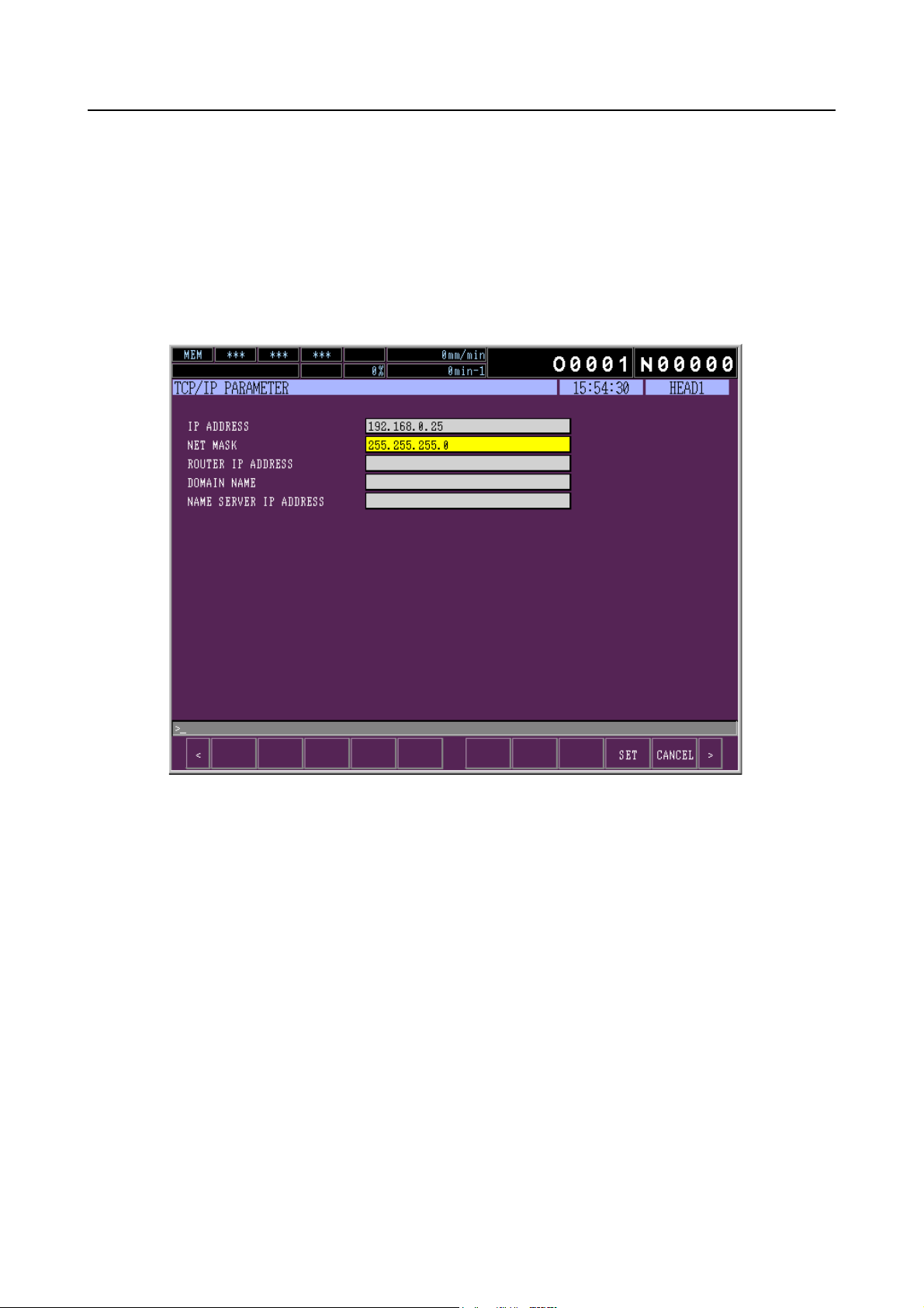
1-3-1 Setting TCP/IP Parameters
Input "2" in the SELECT screen to display the TCP/IP PARAMETER screen.
MORI-SERVER A-33
1. IP ADDRESS (Mandatory)
Set the IP address of the machine.
2. NET MASK (Mandatory)
Set the subnet mask for the machine.
3. ROUTER IP ADDRESS
Set the IP address of the default gateway for the machine.
4. DOMAIN NAME
Set the domain name for the machine.
5. NAME SERVER IP ADDRESS
Set the IP address of the DNS (Domain Name Server) for the machine.

A-34 MORI-SERVER
1-3-2 MORI-SERVER PARAMETER Screen
The MORI-SERVER PARAMETER screen is used to input information necessary for
MORI-SERVER to communicate with the machine.
The MORI-SERVER PARAMETER screen comprises two pages, the basic screen and the detail
screen.
This section explains the items displayed in MORI-SERVER PARAMETER screen.
For the procedure to set MORI-SERVER parameters, refer to page A-38 (1-3-3).
<MORI-SERVER PARAMETER (BASIC) screen>
(1)
(2)
(3)
(4)
(5)
(6)
(7)
(8)
(9)
(10)
(11)
(12)
(13)
<Display Items>
Number Item Explanation
This item is used to validate/invalidate communication with
MORI-SERVER.
0: Invalid
(1) MAIN FUNCTION
1: Valid
When this parameter is set to invalid, any communication
from MORI-SERVER will be rejected.

Number Item Explanation
This item is used to input the port number to be used for the
communication with MORI-SERVER.
MORI-SERVER A-35
(2) PORT NUMBER
NOTE
1. Normally, the default setting "8008" is used.
Change the setting of this parameter only
when the "8008" port is used by other
software.
2. We strongly recommend that you restrict
modification of this parameter only to
persons who have sufficient knowledge of
the network. If this parameter is changed
carelessly to a port used by other software, it
may cause problems with the software using
this port.
3. If the port number is changed, set the same
number for the MORI-SERVER port number
that is set in CHAPTER A, 1-1-3-2 "Setting
Communications Parameters". If different
port numbers are set for MORI-SERVER and
MAPPS, communication cannot be
established.
4. It is necessary to restart MAPPS to make the
changed setting of this parameter effective.
This item is used to input the time period before a time-out
error occurs.
(3) TIME OUT
(4)
IP ADDRESS
CHECK
NOTENOTE
1. Input the time period for time-out error in
seconds.
2. If the set time period for the time-out error is
too short, a time-out error may occur while a
process that takes time is in progress. In
normal operation, set the time period for the
time-out error to 20 or more seconds.
The actual time that causes a time-out error
may differ from the time period set here.
3. It is necessary to restart MAPPS to make the
changed setting of this parameter effective.
This item validates/invalidates the IP address verification
function.
0: Invalid
1: Valid
MAPPS will reject communication from an IP address other
than the IP addresses set for "IP ADDRESS 1" or "IP
ADDRESS 2" if this item is validated.

A-36 MORI-SERVER
Number Item Explanation
This item is used to input an IP address to permit
communication with the machine.
(5) IP ADDRESS 1
(6) IP ADDRESS 2
(7) LOGIN CHECK
(8) USER 1
When inputting an IP address, input it with 8-bit
NOTE
delimiters as in "xxx.xxx.xxx.xxx".
An asterisk "*" can be used as a wildcard when
specifying an IP address.
A wildcard can be specified in a 8-bit unit as in
"xxx.xxx.xxx.*".
It is not possible to use a wildcard to replace
multiple 8-bit delimiters as in "xxx.xxx.*" or to
replace digits smaller than a 8-bit unit as in
"xxx.xxx.xxx.1*".
This item is used to validate/invalidate the login verification
function.
0: Invalid
1: Valid
MAPPS will reject communication if the combination of the
user ID and the password sent from MORI-SERVER does
not match the combination of user ID and password either
for user 1 or user 2 if this item is validated.
This item is used to validate/invalidate the combination of
the user ID and the password set for user 1.
0: Invalid
1: Valid
(9) USER ID This item is used to input the user ID for user 1.
This item is used to input the password for user 1.
(10) PASSWORD
Any letter input in the "PASSWORD" textbox is
NOTE
displayed as an asterisk "*".
This item is used to validate/invalidate the combination of
the user ID and the password set for user 2.
(11) USER 2
0: Invalid
1: Valid
(12) USER ID This item is used to input the user ID for user 2.
This item is used to input the password for user 2.
(13) PASSWORD
Any letter input in the "PASSWORD" textbox is
NOTE
displayed as an asterisk "*".

<MORI-SERVER PARAMETER (DETAIL) screen>
MORI-SERVER A-37
(1) (2)
(3)
<Display Items>
Number Item Explanation
This item is used to validate/invalidate operations to input
NC programs from the MORI-SERVER side to the MAPPS
side.
0: Invalid
(1)
NC PROGRAM
(PC->MAPPS)
1: Valid
It is not permissible to input NC programs from the
MORI-SERVER side to the MAPPS side if this parameter is
invalidated.
This setting is made individually for user 1 and user 2.
This item is used to validate/invalidate operations to output
NC programs from the MAPPS side to the MORI-SERVER
side.
0: Invalid
(2)
NC PROGRAM
(MAPPS->PC)
1: Valid
It is not permissible to output NC programs from the
MAPPS side to the MORI-SERVER side if this parameter is
invalidated.
This setting is made individually for user 1 and user 2.
A-38 MORI-SERVER
Number Item Explanation
(3)
DELETE NC
PROGRAM
1-3-3 Setting MORI-SERVER Parameters
This section describes the procedure for setting the MORI-SERVER parameters.
For details on the MORI-SERVER parameters, refer to page A-34 (1-3-2).
This item is used to validate/invalidate operations to delete
NC programs on the MAPPS side from the MORI-SERVER
side.
0: Invalid
1: Valid
It is not permissible to delete NC programs in the MAPPS
side from the MORI-SERVER side if this parameter is
invalidated.
This setting is made individually for user 1 and user 2.
<Operation Procedure>
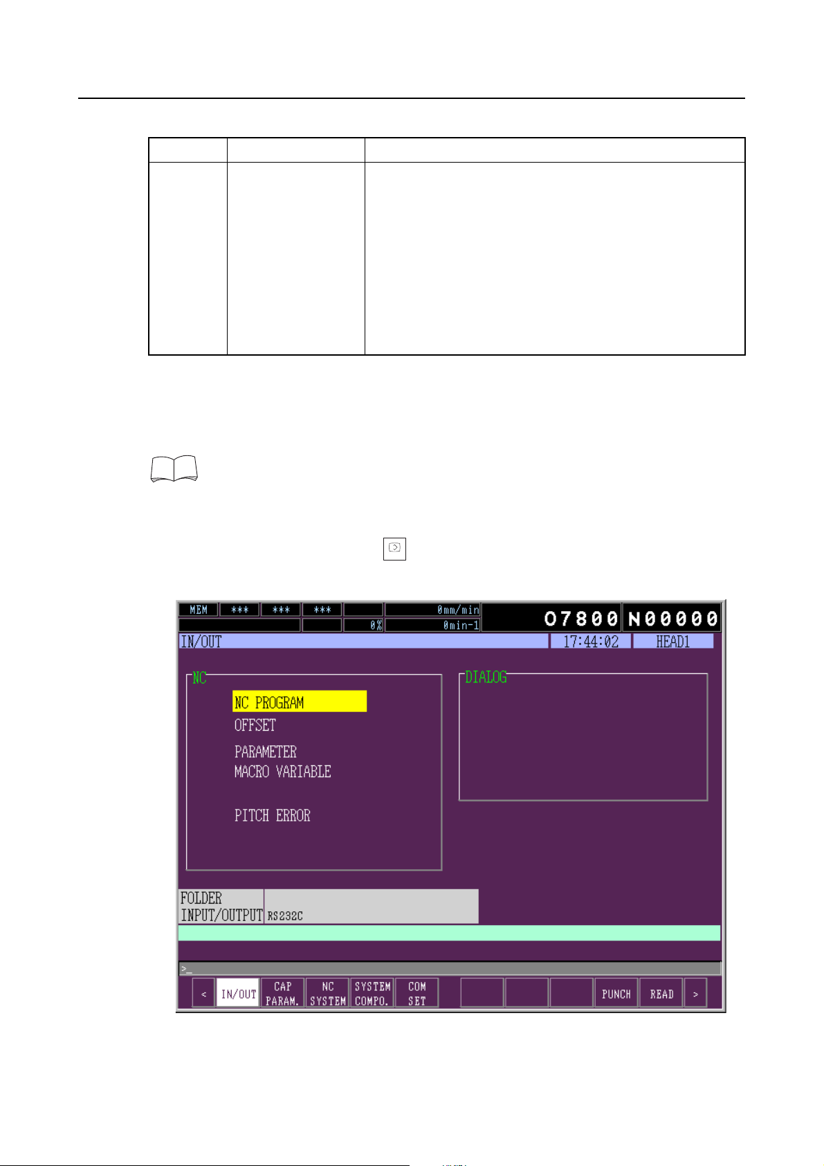
1) Press the function selection key (SYSTEM) at MAPPS.
SYSTEM
The IN/OUT screen is displayed.

2) Press the [COM SET] soft-key.
The SELECT screen is displayed.
MORI-SERVER A-39
3) Input "6" using the data entry keys.
4) Press the (INPUT) key.
INPUT
5) The MORI-SERVER PARAMETER (BASIC) screen is displayed.

A-40 MORI-SERVER
6) Input settings for the required items.
7) Press the [SET] soft-key.
The input data is confirmed and the SELECT screen is displayed.
Be sure to press the [SET] soft-key before switching to another screen. If the screen is
NOTE
switched without pressing the [SET] soft-key, the input data is discarded.
To cancel the MORI-SERVER parameter setting, press the [CANCEL] soft-key.
When the [CANCEL] soft-key is pressed, the input data is discarded and the SELECT
screen is displayed.
8) Press the [DETAIL] soft-key.
9) The MORI-SERVER PARAMETER (DETAIL) screen is displayed.
10) Input settings for the required items.
11) Press the [SET] soft-key.
The input data is confirmed and the SELECT screen is displayed.
Be sure to press the [SET] soft-key before switching to another screen. If the screen is
NOTE
switched without pressing the [SET] soft-key, the input data is discarded.
To cancel the MORI-SERVER parameter setting, press the [CANCEL] soft-key.
When the [CANCEL] soft-key is pressed, the input data is discarded and the SELECT
screen is displayed.
This completes the setting of MORI-SERVER parameters.

1-4 Settings at MAPPS II/III
1-4-1 Setting TCP/IP Parameters
1-4-1-1 How to Display the Setting Screen
MORI-SERVER A-41
1) Display the INPUT/OUTPUT screen by pressing the function selection key (SYSTEM).
SYSTEM

A-42 MORI-SERVER
2) Change the displayed set of soft-keys by pressing the menu selection key [<] once.
3) Press the [COMM. SETNG] soft-key.
The NETWORK SETTING screen is displayed.

MORI-SERVER A-43
• If you enter "1" using the data entry key and press the (INPUT) key on the NETWORK
INPUT
SETTING screen, the BASIC NETWORK SETTING screen where you can set the IP
address of the machine is displayed.
For details of the setting items, see 1-4-1-2 "Basic Network Setting".
• If you enter "6" using the data entry key and press the (INPUT) key on the NETWORK
INPUT
SETTING screen, the MORI-NET COMMON SETTING screen is displayed so that you can
set the MORI-NET parameters.
For details of the setting items, see MORI-NET Global Edition OPERATION MANUAL.
• If you enter "5" using the data entry key and press the (INPUT) key on the NETWORK
INPUT
SETTING screen, the MORI-MONITOR SCREEN TRANSIT SETTING screen is displayed
you can set the MORI-MONITOR parameters.
For details of the setting items, see MORI-NET Global Edition OPERATION MANUAL.

A-44 MORI-SERVER
1-4-1-2 Basic Network Setting
<Setting items>
Item Description
DHCP FUNCTION This is the setting for the DHCP function that automatically
allocates the IP address.
Select "INVALID" when using the MORI-SERVER function.
IP ADDRESS
SUBNET MASK
DEFAULT GATEWAY
Set the IP address to be allocated to the machine.
Set the subnet mask at the machine.
Set the default gateway address.
DNS SERVICE Set whether or not you use the DNS service.
VALID: Select "VALID" if you use the DNS service.
INVALID: Select "INVALID" if you do not use the DNS service.
DNS SERVER Set the IP address of the DNS server. Setting is not possible if
your selection for "DNS SERVICE" is "INVALID".
MAC ADDRESS The MAC address of the machine is displayed. This data
cannot be changed.

<Soft-keys>
MORI-SERVER A-45
Soft-key
No.
F6 PING
Item Description
<PING function>
F8 GET Automatically inputs the setting value of the selected item.
F9 SET Saves the changes that you have made on this screen.
F10 RETURN Exits from this setting screen and returns to the BASIC
NETWORK SETTING screen.
<PING function>
The PING function is used to confirm that network connection with the specified IP address is
established.
If you enter the IP address to confirm network connection and press the [PING] soft-key, the
screen shows the corresponding message depending on whether or not the network connection is
established.
When the network connection is confirmed

A-46 MORI-SERVER
When the network connection is not confirmed

1-4-2 MORI-SERVER PARAMETER Screen
Open the MORI-SERVER PARAMETER screen at MAPPS II/III as follows.
MORI-SERVER A-47
1) Press the (SYSTEM) key among the function keys on the MAPPS operation panel.
SYSTEM
The screen indicated in Fig. A-38 will be displayed.
2) Press the menu switching key [<].
Fig. A-38
The soft-keys will change as indicated in Fig. A-39.
3) Press the [COMM. SETNG] soft-key.
Fig. A-39

A-48 MORI-SERVER
The NETWORK SETTING screen will be displayed (Fig. A-40).
Fig. A-40
4) Enter "4" with the data entry keys.
5) Press the (INPUT) key.
INPUT
The MORI-DSN FUNCTION SETTING screen is displayed, as indicated in Fig. A-41.
Fig. A-41
6) To change the MORI-SERVER function basic settings, press the [SERVER BASIC] soft-key.
7) To change the MORI-SERVER function detailed settings, press the [SERVER DETAIL]
soft-key.

1-4-3 MORI-SERVER FUNCTION BASIC SETTING Screen
This screen is used to set the basic parameters for communications using MORI-SERVER.
Set the basic parameters for MORI-SERVER by following the procedure below.
1) Display the MORI-SERVER FUNCTION BASIC SETTING screen (1-4-2 "MORI-SERVER
PARAMETER Screen" (page A-47)) by following the procedure in Fig. A-42.
MORI-SERVER A-49
Fig. A-42
2) At "PORT NUMBER" on this screen, enter the port number that is to be used for
MORI-SERVER communications.
3) At "TIME OUT (sec.)" set the period before a time-out error occurs in MORI-SERVER
communications.
NOTE
1. If the time set for this parameter is too short, time out may occur if processing takes
some time, so make the setting 20 seconds or longer.
2. The actual time that causes a timeout error may differ from the time period set here.
3. To make changes to these parameters effective, the MAPPS II/III power must be turn
OFF and back ON.
4) At "MAIN FUNCTION" select whether MORI-SERVER communications are enabled or
disabled.
If you set "INVALID" here, attempts to communicate from a PC will be rejected.
Normally, the default setting "8008" is used. Change the setting of this parameter only
NOTE
when the "8008" port is used by other software.
CAUTION
This parameter setting should only be changed by a person with a good knowledge of
the network. If the number of a port that is being used by other software is specified, it
may cause problems with the software using that port.

A-50 MORI-SERVER
NOTE
1. Set the same value for this parameter as set for the PC port number in 1-1-3-2
"Setting Communications Parameters" (page A-6). If this parameter setting and the
port number set at the PC are different, communications cannot be established.
2. To make a change to this parameter effective, the MAPPS II/III power must be turn
OFF and back ON.
5) AT "IP ADDRESS AUTHORIZATION FUNCTION" select whether or not communications
are to be restricted based on the IP address.
If you select "VALID" here, the "IP ADDRESS 1" and "IP ADDRESS 2" fields will be
highlighted in color as shown in Fig. A-43 and entry will be possible in these fields.
When communications are restricted based on the IP address, it means that attempts to
communicate from addresses other than those specified here are rejected.
Fig. A-43
6) If you select "VALID" for "IP ADDRESS AUTHORIZATION FUNCTION" in Fig. A-42, enter
the IP addresses from which communications are permitted at "IP ADDRESS 1" and "IP
ADDRESS 2" in Fig. A-43 in the format "xxx.xxx.xxx.xxx".
A wildcard "∗" can be used in this setting. If you do use a wild card, use it in a format
whereby one delimiter among eight bits can be replaced with "∗", like this: "xxx.xxx.xxx.∗".
Usages such as "xxx.xxx.∗" and "xxx.xxx.xxx.1∗" are not acceptable.

MORI-SERVER A-51
7) At "USER AUTHORIZATION FUNCTION" in Fig. A-42, select whether the user authorization
function is enabled or disabled.
If you select "VALID" here, the "USER 1" and "USER 2" fields will become highlighted in
color as indicated in Fig. A-44 and you will be able to make VALID/INVALID settings for user
1 and user 2.
1. The user authorization function is a function that checks whether the user ID and
password sent from a PC match the user ID and password pre-registered at MAPPS
and rejects the communication if they do not match. Set the user IDs and passwords
for which communications are permitted as follows.
2. If the user authorization function is disabled (INVALID), the operation is the same as
when communications are authorized for user 1.
Fig. A-44

A-52 MORI-SERVER
8) At "USER 1" in Fig. A-44, select whether the user ID and password set for user 1 in the
manner described below are valid or invalid.
If you select "VALID" here, the user 1 "USER ID", and "PASSWORD" fields will be
highlighted in color as shown in Fig. A-45 and entry will be possible in these fields.
Fig. A-45
9) Enter the user ID and password for user 1 in the "USER ID" and "PASSWORD" fields in Fig.
A-45.
The characters entered for the password will be displayed as asterisks.

MORI-SERVER A-53
10) At "USER 2" in Fig. A-44, select whether the user ID and password set for user 2 in the
manner described below are valid or invalid.
If you select "VALID" here, the user 2 "USER ID" and "PASSWORD" fields will be highlighted
in color as shown in Fig. A-46 and entry will be possible in these fields.
Fig. A-46
11) Enter the user ID and password for user 2 in the "USER ID" and "PASSWORD" fields in Fig.
A-46.
The characters entered for the password will be displayed as asterisks.
12) Press the [GET] soft-key (Fig. A-46).
You can obtain the data from the field selected with the cursor in the textbox.
13) When you have completed the parameter entry procedure from 2) through 11), press the
[SET] soft-key.
The entered data will be set at MAPPS II/III.

A-54 MORI-SERVER
By pressing the [MORI DSN], [SERVER DETAIL] or [RETURN] soft-key rather than
[SET], you can display the soft-key menu shown in Fig. A-47. Press [OK] in this menu to
discard the entered data (it will not be set in MAPPS) and display the screen that
corresponds to the soft-key you pressed, as indicated below.
If you pressed the [MORI DSN] soft-key, the MORI-DSN FUNCTION SETTING screen
shown in Fig. A-41 is displayed.
If you pressed the [SERVER DETAIL] soft-key, the MORI-SERVER DETAIL SETTING
screen shown in Fig. A-49 is displayed.
If you pressed the [RETURN] soft-key, the NETWORK SETTING screen shown in Fig. A-40
is displayed.
Pressing the [SERVER BASIC] soft-key will not cause any change.
Fig. A-47

1-4-4 MORI-SERVER DETAIL SETTING Screen
This screen is used to set the "VALID" or "INVALID" status for individual functions as the detailed
communications parameters for MORI-SERVER.
Follow the procedure below to set the detailed MORI-SERVER parameters.
With regard to the settings in steps 2) through 6), if you are authorized as User 1 or the
user authorization function is invalid, enter the data set at "USER 1" in Fig. A-48, and if you
are authorized as User 2, enter the data set at "USER 2".
MORI-SERVER A-55
Fig. A-48
1) Follow the procedure in 1-4-2 "MORI-SERVER PARAMETER Screen" (page A-47) to
display the MORI-SERVER DETAIL SETTING screen (Fig. A-49).
Fig. A-49

A-56 MORI-SERVER
2) In the "PC → MAPPS" column of the NC PROGRAM INPUT/OUTPUT settings in Fig. A-49,
select whether to permit or prohibit the function for inputting programs from a PC into the
NC unit running MAPPS II/III (2-2-4 "Individual NC Program Input Function" (page A-73)
and 2-2-7 "All NC Program Input Function" (page A-85)) by selecting the [PROHIBIT] or
[PERMIT] soft-key.
If you select PERMIT, the FOREGROUND PROGRAM and BG EDIT PROGRAM fields will
be highlighted in color and you will be able to select the PERMIT or PROHIBIT option for
these items.
Even if you select PERMIT here, it may not be possible to run the program due to the NC
NOTE
settings.
3) In the "MAPPS → PC" column of the NC PROGRAM INPUT/OUTPUT settings in Fig. A-49,
select whether to permit or prohibit the function for inputting programs from the NC unit
running MAPPS II/III to a PC (2-2-3 "Individual NC Program Output Function" (page A-68)
and 2-2-6 "All NC Program Output Function" (page A-81)) by selecting the [PROHIBIT] or
[PERMIT] soft-key.
Even if you select PERMIT here, it may not be possible to run the program due to the NC
NOTE
settings.
4) At FOREGROUND PROGRAM in Fig. A-49, select whether, when an NC program is input
from a PC to the NC unit running MAPPS II/III and an NC program with the same program
number as the foreground program is found to exist at the MAPPS II/III side, overwriting of
the existing program is permitted or prohibited, using the [PERMIT] or [PROHIBIT] soft-key.
Even if you select PERMIT here, it may not be possible to overwrite the program due to
NOTE
the NC settings.
5) At BG EDIT PROGRAM in Fig. A-49, select whether, when an NC program is input from a
PC to the NC unit running MAPPS II/III and an NC program with the same program number
as the program being edited in the background is found to exist at the MAPPS II/III side,
overwriting of the existing program is permitted or prohibited, using the [PERMIT] or
[PROHIBIT] soft-key.
Even if you select PERMIT here, it may not be possible to overwrite the program due to
NOTE
the NC settings.
6) In the "PC → MAPPS" column at NC PROGRAM DELETE in Fig. A-49, select whether to
permit or prohibit the function for deleting NC programs from inside the NC running MAPPS
II/III (2-2-5 "NC Program Delete Function" (page A-77) and 2-2-11 "Conversational Program
Delete Function" (page A-99)) with the [PERMIT] or [PROHIBIT] soft-key.
Even if you select PERMIT here, it may not be possible to overwrite the program due to
NOTE
the NC settings.
7) In the "PC → MAPPS" column at CONVERSATION PROGRAM INPUT/OUTPUT in Fig.
A-49, select whether to permit or prohibit the function for inputting conversational programs
from the PC into the NC running MAPPS II/III with the [PERMIT] or [PROHIBIT] soft-key. If
you select PERMIT, the CONVERSATION PROGRAM OVERWRITE "PERMIT" or
"PROHIBIT" option will be highlighted in color and you will be able to change this setting.
8) In the "MAPPS → PC" column at CONVERSATION PROGRAM INPUT/OUTPUT in Fig.
A-49, select whether to permit or prohibit the function for inputting conversational programs
from the NC running MAPPS II/III to a PC with the [PERMIT] or [PROHIBIT] soft-key.

MORI-SERVER A-57
9) At CONVERSATION PROGRAM OVERWRITE in Fig. A-49, use the [PERMIT] or
[PROHIBIT] soft-key to select whether when a conversational program is input from a PC to
the NC running MAPPS II/III and the same program is found to exist already at MAPPS II/III,
overwriting of the existing program is permitted or prohibited.
10) In the "PC → MAPPS" column at CONVERSATION DATA INPUT/OUTPUT in Fig. A-49, use
the [PERMIT] or [PROHIBIT] soft-key to select whether the function for inputting
conversational data from a PC to the NC running MAPPS II/III is permitted or prohibited.
11) In the "MAPPS → PC" column at CONVERSATION DATA INPUT/OUTPUT in Fig. A-49, use
the [PERMIT] or [PROHIBIT] soft-key to select whether the function for outputting
conversational data from the NC running MAPPS II/III to a PC is permitted or prohibited.
12) In the "PC → MAPPS" column at CARD DNC INPUT/OUTPUT in Fig. A-49, use the
[PERMIT] or [PROHIBIT] soft-key to select whether the function for inputting files from a
personal computer to the card DNC area in the MAPPS II/III is permitted or prohibited.
13) In the "MAPPS → PC" column at CARD DNC INPUT/OUTPUT in Fig. A-49, use the
[PERMIT] or [PROHIBIT] soft-key to select whether the function for outputting files and
folders from the card DNC area in the MAPPS II/III to a personal computer is permitted or
prohibited.
14) At CARD DNC OVERWRITE in Fig. A-49, use the [PERMIT] or [PROHIBIT] soft-key to
select whether, if a program is input from a personal computer to the card DNC area in the
MAPPS II/III and a program of the same name already exists in the MAPPS, overwriting of
the existing program is permitted or prohibited.
15) At CARD DNC DELETE in Fig. A-49, use the [PERMIT] or [PROHIBIT] soft-key to select
whether the function for deleting files from the card DNC area in the MAPPS II/III is
permitted or prohibited.
16) When entry of the parameter data described above is completed (Fig. A-49), press the
[SET] soft-key.
The data entered will be set in MAPPS II/III.
By pressing the [MORI DSN], [SERVER BASIC] or [RETURN] soft-key rather than [SET],
you can display the soft-key menu shown in Fig. A-50. Press [OK] in this menu to discard
the entered data (it will not be set in MAPPS) and display the screen that corresponds to
the soft-key you pressed, as indicated below.
Fig. A-50

A-58 MORI-SERVER
If you pressed the [MORI DSN] soft-key, the MORI-DSN FUNCTION SETTING screen
shown in Fig. A-41 is displayed.
If you pressed the [SERVER BASIC] soft-key, the MORI-SERVER BASIC SETTING screen
shown in Fig. A-42 is displayed.
If you pressed the [RETURN] soft-key, the NETWORK SETTING screen shown in Fig. A-40
is displayed.
Pressing the [SERVER DETAIL] soft-key will not cause any change.

2 COMMUNICATION FUNCTIONS
This section explains operations for communications with MAPPS using MORI-SERVER.
2-1 Selecting the Communication Target Machine
With MORI-SERVER, you first select the machine to be the communication target and then you
can perform various types of communication in relation to that machine. There are the following
two methods for selecting the communication target machine.
First select the communication target machine by using either of these methods, then perform the
communications operations described below.
2-1-1 Selection from the List of Registered Machines
In this method, the communication target machine is selected from among the machines that were
registered in advance. This method allows you to register information like the IP address, user ID,
and password so that this information does not have to be entered.
MORI-SERVER A-59
Select the communication target machine in the manner described below.
Fig. A-51
For details on the procedure for registering machine information, see 1-2-4-1 "New
Machine Registration" (page A-18).

A-60 MORI-SERVER
1) Select the "List" radio button on the screen in Fig. A-52.
The registered machines will be displayed in the machine name display area, as shown in
Fig. A-53.
2) Select the machine to be set as the communication target.
Fig. A-52
Fig. A-53
The information for this machine will be displayed in the machine information display area,
as shown in Fig. A-54, completing selection of the communication target machine.
Fig. A-54

2-1-2 Manual Selection
The communication target machine can be set by individually entering the IP address of the
machine, the user ID and password when, for example, communicating with machines that are not
registered. Follow the procedure below to set the target in this way.
MORI-SERVER A-61
Fig. A-55
1) Select the "Manual" radio button in Fig. A-56.
Fig. A-56

A-62 MORI-SERVER
2) In the "IP Address" textbox under "Manual Setting" in Fig. A-57, enter the IP address of the
machine to which the connection is to be made.
3) In the "User ID" textbox under "Manual Setting" in Fig. A-57, enter the user ID registered at
the machine to which the connection is to be made.
This textbox can be left empty if user verification is disabled on the machine to be set as
NOTE
the communication target.
Fig. A-57
4) In the "Pass Word" textbox under "Manual Setting" in Fig. A-57, enter the password
associated with the user ID that you have specified.
The entered password is displayed as asterisks.
This textbox can be left empty if user verification is disabled on the machine to be set as
NOTE
the communication target.
5) When entry of items 1) through 4) is completed as shown in Fig. A-58, click the [SET] button.
Fig. A-58
The entered information is displayed in the machine information display area as shown in
Fig. A-59. This completes setting of the communication target machine.
Fig. A-59
In the case of manual selection, conversational programs cannot be input or output.
NOTE

2-2 Communications Operations
This section describes the communications operations of MORI-SERVER.
In order to perform these operations you must first have selected the communication target
machine as described in 2-1 "Selecting the Communication Target Machine" (page A-59).
2-2-1 Message Transmit Function
MORI-SERVER provides a function for transmitting simple messages to the communication target
machines. When a message is transmitted from MORI-SERVER, a message box appears on the
MAPPS screen of the communication target machine to display the message.
This section explains the procedure for transmitting a message to MAPPS.
1) Click the [Message] button.
The "Message Input" dialog box appears.
MORI-SERVER A-63
Message entry area
Fig. A-60
2) Enter the message to be transmitted in the message entry area. It can be up to 40
characters in length.
NOTE
1. When entering a message, use only characters that MAPPS can display correctly. A
message containing symbols or other elements that MAPPS cannot display will not
be displayed correctly.
2. Up to 256 characters can be entered in the Message Input dialog box. However,
MAPPS can display a maximum of only 40 characters or so. If a message longer
than the number of characters that MAPPS can display is entered, message
transmission will fail.
The priority of the message to be sent is set as "normal". For details on priorities, see
6-2 "Message Priority Levels" (page A-157).
3) To send the message that you have entered, press the [OK] button in the "Message Input"
dialog box.
To cancel transmission of the message, click the [Cancel] button.

A-64 MORI-SERVER
When the communication is successfully completed, the message "Communication
Success." is displayed in the message display area (Fig. A-61).
If the communication fails, an error message dialog box like the one in Fig. A-62 is displayed
and an error message is displayed in the message display area.
Fig. A-61
Fig. A-62
For details on error messages, see 4-2 "Contents of Error Messages" (page A-146).

2-2-2 NC Program List Obtaining Function
MORI-SERVER provides a function for obtaining the list of NC programs stored in the NC unit of
the communication target machine and displaying it in the NC program list area at a PC.
This section explains the procedure for obtaining the list of NC programs.
1) Click the "NC Program" tab (Fig. A-63).
MORI-SERVER A-65
Fig. A-63
2) Select the NC unit whose NC program list is to be obtained by pressing the [Head 1] button
or the [Head 2] button (Fig. A-64).
Fig. A-64
For the machine with which "2 Head Machine" is selected in the "Machine Information"
NOTE
dialog box, it is not possible to press the [Head 2] button.

A-66 MORI-SERVER
The selected head number is indicated in the head display area for the communication
target machine (Fig. A-65).
As shown in Fig. A-64, the button for the selected head will be shown depressed. (In Fig.
A-64 the [Head 2] button is selected.)
If the communication target machine has one head only, do not select [Head 2].
NOTE
3) Click the [Refresh] button (Fig. A-64).
Communication starts.
When the communication is successfully completed, the message "Communication
Success." is displayed in the message display area.
Fig. A-65
Fig. A-66
If the communication fails, an error message dialog box like the one in Fig. A-67 is displayed
and an error message is displayed in the message display area.
Fig. A-67
For details on error messages, see 4-2 "Contents of Error Messages" (page A-146).

MORI-SERVER A-67
When the communication is successfully completed, the obtained NC program list is
displayed in the NC program list display area.
Fig. A-68
Information on the program storage area of the communication target NC is displayed in the
NC program list display area, as shown in page A-67 (Fig. A-69).
Fig. A-69

A-68 MORI-SERVER
2-2-3 Individual NC Program Output Function
This function is equivalent to the NC program output function that can be executed from the
PROGRAM screen of MAPPS. Using this function, you can select one or more programs stored
in an NC of the communication target machine and output them to files of your choice in a
personal computer.
This section explains the procedure for outputting NC programs individually to MAPPS.
1) By following the procedure in 2-2-2 "NC Program List Obtaining Function" (page A-65),
display the list of NC programs in the NC unit serving as the program output source in the
NC program list display area (Fig. A-70).
Fig. A-70

MORI-SERVER A-69
2) Select the program or programs to be output by clicking on them in the NC program list
display area (Fig. A-71).
Fig. A-71
The following three methods are available for selecting multiple NC programs.
• As shown in Fig. A-72, click the required programs while holding down the [Ctrl] key.
Fig. A-72

A-70 MORI-SERVER
• As shown in Fig. A-73, select a series of programs by clicking the first and then the last
NC program in the series while holding down the [Shift] key.
Fig. A-73
• Specifying a range with the mouse
When you select multiple NC programs, all the programs are output to a single file.
3) As shown in Fig. A-74, select the output destination folder from the I/O destination folder
selection area.
Fig. A-74

4) Click the [>] button (Fig. A-75).
MORI-SERVER A-71
Fig. A-75
As an alternative to clicking the [>] button, you can drag and drop the specified program
into the file list display area.
The "File Name Input" dialog box appears (Fig. A-76).
5) Enter the filename of the file to be output in the textbox.
Fig. A-76
NOTE
1. If the default file name function is enabled, the default file name is shown in the
textbox.
2. If the default extension function is enabled, the default extension is automatically
appended to the file name on output even if it had not been added in the textbox.
3. If the default extension function is enabled, the default extension is appended
unconditionally even if an extension other than the default has been added in the
textbox.

A-72 MORI-SERVER
6) To execute NC program output, click the [OK] button (Fig. A-76).
To cancel output, click the [Cancel] button.
When output is successfully completed, the message "Communication Success." will be
displayed in the message display area.
If the communication fails, an error message box appears (Fig. A-78) and an error message
is displayed in the message area.
Fig. A-77
Fig. A-78
For details on error messages, see 4-2 "Contents of Error Messages" (page A-146).

2-2-4 Individual NC Program Input Function
This function is equivalent to the NC program input function that can be executed from the
PROGRAM screen of MAPPS. It allows you to input NC programs from a program file stored in a
personal computer into an NC unit.
This section explains the procedure for inputting NC programs individually.
1) Click the "NC Program" tab (Fig. A-79).
MORI-SERVER A-73
Fig. A-79
2) Select the NC unit that is to accept the program input by clicking the [Head 1] button or the
[Head 2] button (Fig. A-80).
Fig. A-80
For the machine with which "2 Head Machine" is selected in the "Machine Information"
NOTE
dialog box, it is not possible to press the [Head 2] button.

A-74 MORI-SERVER
The selected head number is indicated in the head display area (Fig. A-81).
As shown in Fig. A-80, the button for the selected head will be shown depressed. (In Fig.
A-80 the [Head 2] button is selected.)
If the communication target machine has one head only, do not select [Head 2].
NOTE
3) In the input and output folder selection area (Fig. A-82), select the folder where the file to be
input is located.
Fig. A-81
Fig. A-82
4) The file to be input is selected in the file list display area, as shown in Fig. A-83.
Fig. A-83
Multiple files can be specified by using the same method as for the individual NC program
output function. In this case a dialog box (Fig. A-85) is displayed for each file to be input.

5) Click the [<] button (Fig. A-84).
MORI-SERVER A-75
Fig. A-84
As an alternative to clicking the [<] button, you can drag and drop the specified file into the
NC program list display area.
A message asking you to confirm the input will appear (Fig. A-85).
6) To proceed with the input, click the [OK] button.
To cancel input, click the [Cancel] button.
Fig. A-85

A-76 MORI-SERVER
When input is successfully completed, the message "Communication Success." will be
displayed in the message display area.
If the communication fails, an error message box appears (Fig. A-87) and an error message
is displayed in the message area.
Fig. A-86
Fig. A-87
For details on error messages, see 4-2 "Contents of Error Messages" (page A-146).
If multiple program files are selected in step 4), the program files will be transmitted one by
one. Therefore the message to confirm the file transmission (Fig. A-85) and the message
to notify completion of the NC program input will be displayed for each file.
When the transmission of all the selected files is completed, 2-2-2 "NC Program List
Obtaining Function" (page A-65) is automatically executed to refresh the contents of the NC
program list display area.

2-2-5 NC Program Delete Function
This function is equivalent to the individual NC program delete function that can be executed from
the PROGRAM screen of MAPPS.
This section explains the procedure for deleting NC programs.
1) By following the procedure in 2-2-2 "NC Program List Obtaining Function" (page A-65),
display the list of NC programs in the NC unit serving as the program output source in the
NC program list display area (Fig. A-88).
MORI-SERVER A-77
Fig. A-88

A-78 MORI-SERVER
2) Select the program or programs to be deleted by clicking on them in the NC program list
display area (Fig. A-89).
Fig. A-89
The following two methods are available for selecting multiple NC programs.
• As shown in Fig. A-90, click the required programs while holding down the [Ctrl] key.
Fig. A-90

MORI-SERVER A-79
• As shown in Fig. A-91, select a series of programs by clicking the first and then the last
NC program in the series while holding down the [Shift] key.
Fig. A-91
3) Click the [Delete] button (Fig. A-92).
Fig. A-92

A-80 MORI-SERVER
A message asking you to confirm the deletion will appear (Fig. A-93).
4) To proceed with the deletion, click the [OK] button.
To cancel deletion, click the [Cancel] button.
When deletion is successfully completed, the message "Communication Success." will be
displayed in the message display area (Fig. A-94).
Fig. A-93
Fig. A-94
If the communication fails, an error message box appears (Fig. A-95) and an error message
is displayed in the message area.
Fig. A-95
For details on error messages, see 4-2 "Contents of Error Messages" (page A-146).

If multiple program files are selected in step 2), the program files will be deleted one by
one. Therefore the message to confirm the file deletion (Fig. A-93) and the message to
notify completion of the NC program deletion will be displayed for each file.
When the deletion of all the selected files is completed, 2-2-2 "NC Program List Obtaining
Function" (page A-65) is automatically executed to refresh the contents of the NC program
list display area.
2-2-6 All NC Program Output Function
This function is equivalent to the NC program output function that can be executed from the IN/
OUT screen of MAPPS. It allows you to output all of the NC programs stored in an NC unit of the
machine in a batch.
Follow the procedure below to output all the NC programs in a batch.
1) Select the "System" tab (Fig. A-96).
MORI-SERVER A-81
Fig. A-96
2) Select the NC unit from which the programs are to be output by clicking the [Head 1] button
or the [Head 2] button (Fig. A-97).
Fig. A-97

A-82 MORI-SERVER
For the machine with which "2 Head Machine" is selected in the "Machine Information"
NOTE
dialog box, it is not possible to press the [Head 2] button.
The selected head number is indicated in the head display area for the communication
target machine (Fig. A-98).
As shown in Fig. A-97, the button for the selected head will be shown depressed. (In Fig.
A-97 the [Head 2] button is selected.)
If the communication target machine has one head only, do not select [Head 2].
NOTE
3) In input/output selection area (Fig. A-99), select the "NC Program" radio button.
Fig. A-98
Fig. A-99

MORI-SERVER A-83
4) As shown in Fig. A-100, select the output destination folder from the I/O destination folder
selection area.
Fig. A-100
5) Click the [>] button (Fig. A-101).
Fig. A-101
The "File Name Input" dialog box appears (Fig. A-102).
6) Enter the filename of the file to be output in the textbox.
Fig. A-102

A-84 MORI-SERVER
NOTE
1. Even when the default file name function is enabled, the default file name is not
shown in the textbox for "all NC program output".
2. If the default extension function is enabled, the default extension is appended
unconditionally even if an extension other than the default has been added in the
textbox.
7) To execute NC program output, click the [OK] button (Fig. A-102).
To cancel output, click the [Cancel] button.
When the output is successfully completed, the message "Communication Success." is
displayed in the message display area (Fig. A-103).
Fig. A-103
If the communication fails, an error message box appears (Fig. A-104) and an error
message is displayed in the message area.
Fig. A-104
For details on error messages, see 4-2 "Contents of Error Messages" (page A-146).

2-2-7 All NC Program Input Function
This function is equivalent to the NC program input function that can be executed from the IN/OUT
screen of MAPPS. It allows you to input all of the NC programs stored in files at a personal
computer into an NC unit of the machine.
Follow the procedure below to input all the NC programs in a batch.
1) Select the "System" tab (Fig. A-105).
MORI-SERVER A-85
Fig. A-105
Select the NC unit into which the programs are to be input by clicking the [Head 1] button or the
[Head 2] button (Fig. A-106).
Fig. A-106
For the machine with which "2 Head Machine" is selected in the "Machine Information"
NOTE
dialog box, it is not possible to press the [Head 2] button.

A-86 MORI-SERVER
2) The selected head number is indicated in the head display area for the communication
target machine (Fig. A-107).
As shown in Fig. A-106, the button for the selected head will be shown depressed. (In Fig.
A-106 the [Head 2] button is selected.)
If the communication target machine has one head only, do not select [Head 2].
NOTE
3) In input/output selection area (Fig. A-108), select the "NC Program" radio button.
Fig. A-107
Fig. A-108

MORI-SERVER A-87
4) In input/output folder selection area (Fig. A-109), select the folder where the files to be input
are located.
Fig. A-109
5) Select the file to be input in the file list display area as shown in Fig. A-110.
Fig. A-110
6) Click the [<] button (Fig. A-111).
Fig. A-111

A-88 MORI-SERVER
A message asking you to confirm the input will appear (Fig. A-112).
7) To proceed with the input, click the [OK] button.
To cancel input, click the [Cancel] button.
Fig. A-112
When the input is successfully completed, the message "Communication Success." is
displayed in the message display area (Fig. A-113).
Fig. A-113
If the communication fails, an error message box appears (Fig. A-114) and an error
message is displayed in the message area.
Fig. A-114
For details on error messages, see 4-2 "Contents of Error Messages" (page A-146).

If multiple program files are selected in step 4), the program files will be transmitted one by
one. Therefore the message to confirm the file transmission (Fig. A-112) and the message
to notify completion of the NC program input will be displayed for each file.
2-2-8 Conversational Program List Obtaining Function
MORI-SERVER provides a function for obtaining the list of programs stored in the target MAPPS
and displaying it in the CAPS program list display area at a personal computer.
This section explains the procedure for obtaining the list of conversational programs.
1) Click the "CAPS" tab (Fig. A-115).
MORI-SERVER A-89
Fig. A-115
2) Click the [Refresh] button (Fig. A-115).
Communication starts.
When the communication is successfully completed, the message "Communication
Success." is displayed in the message display area.
Fig. A-116
 Loading...