

Mopar K6862043 Installation Instructions Manual
Backup Camera
1
www.mopar.com
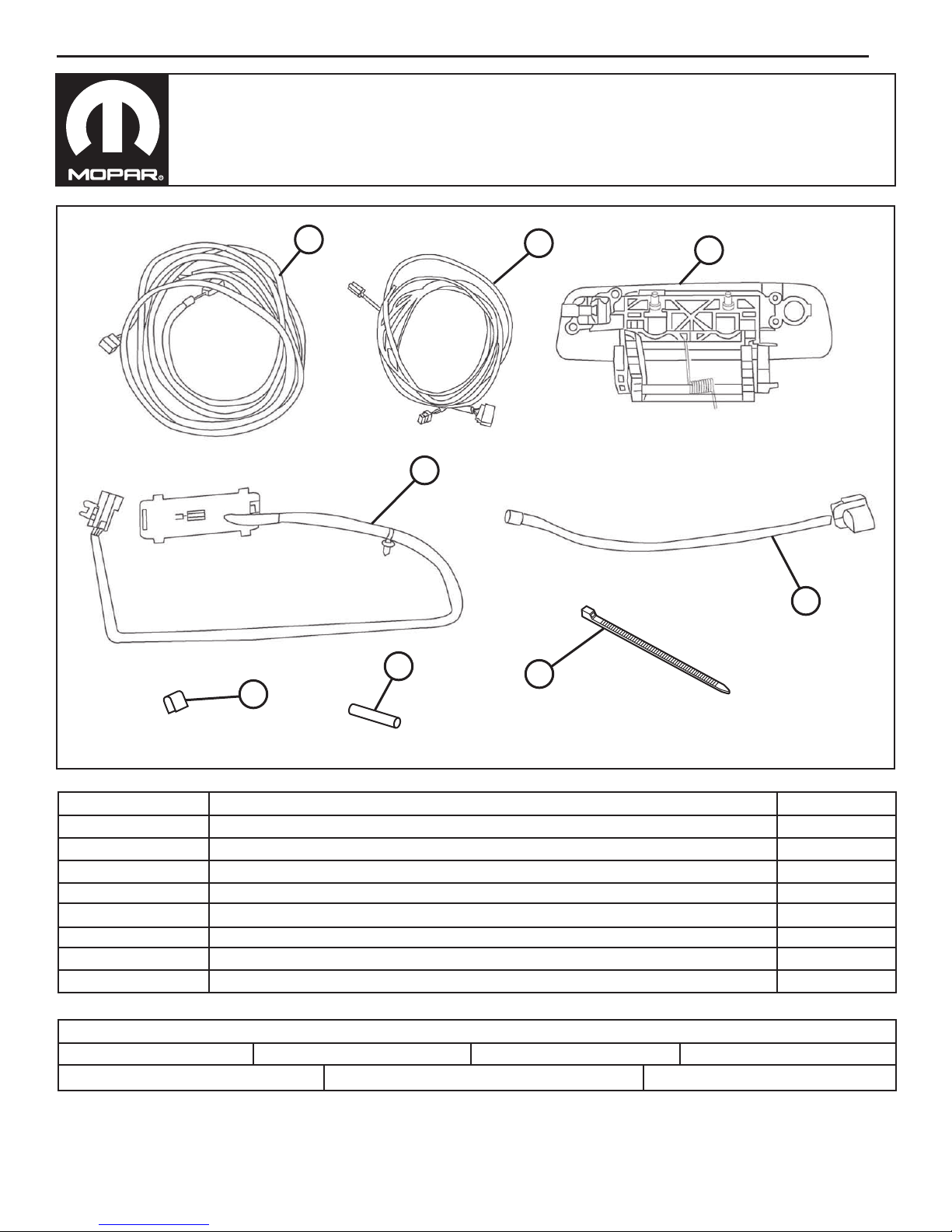
A
D
F
G
B
H
C
E
CALL OUT
A
B
C
D
E
F
G
H
Grease Pencil
Metric Socket Set
3/11/14
DESCRIPTION
Camera Body Harness
Radio Harness
Handle with Camera Provisions
Camera/Lock Jumper Harness
Tailgate Wire Harness
Shrink Tube
Splice Clip
Cable Tie
TOOLS REQUIRED
Phillips Screwdriver
QUANTITY
1
1
1
1
1
3
3
60
Trim Stick
Crimping ToolWire Cutters RTV Sealant 82300234
K6862043
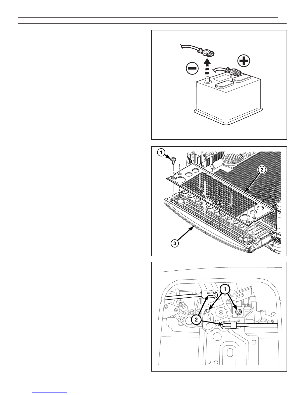
1. Loosen one (1) 10mm bolt and disconnect
negative battery cable
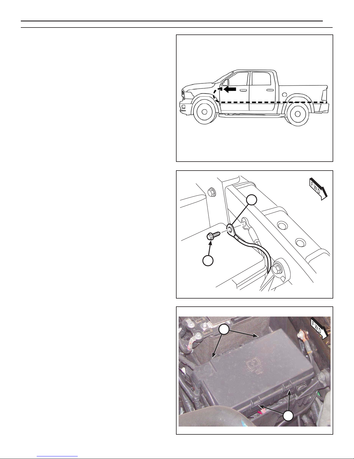
NOTE: Vehicle with tailgate liner shown.
The tailgate liner and tailgate cover are
removed and installed as one piece.
www.mopar.com
2
2. Open the tailgate.
3. If equipped with tailgate liner (2), remove screws (1)
and remove the tailgate cover.
4. Using a grease pencil or equivalent, mark the
location of the actuator rods (2) at the latch control.
5. Disconnect the actuator rods from the latch control.
3/11/14
K6862043
www.mopar.com
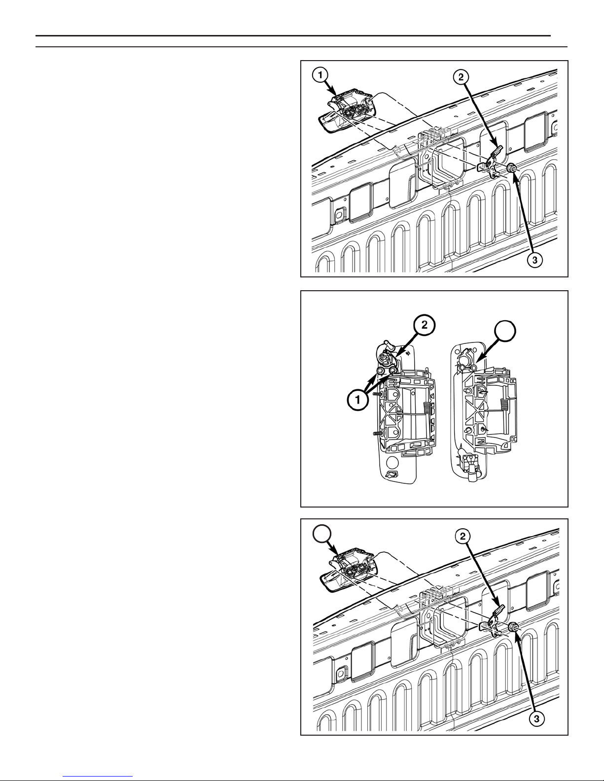
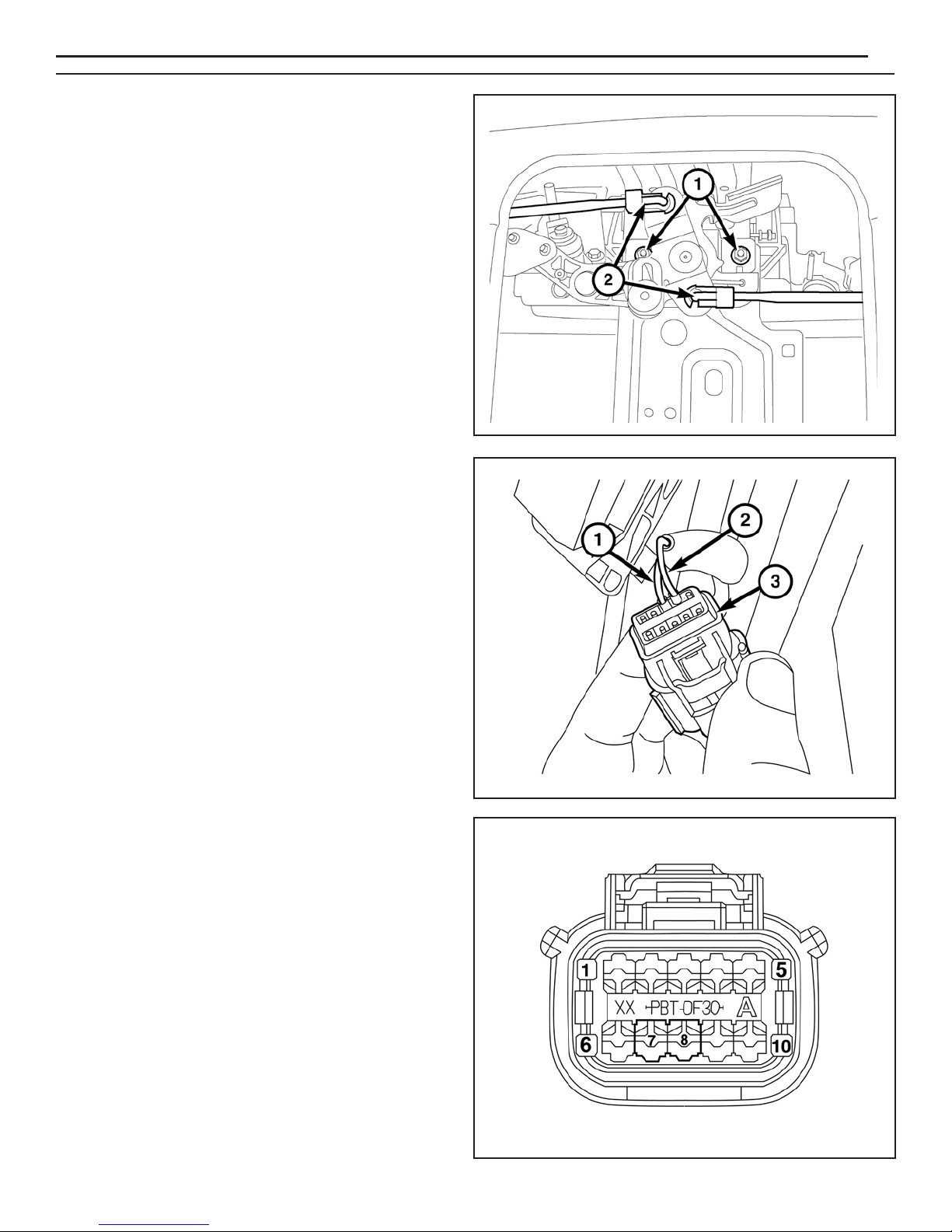
6. Remove the two nuts (3) that secure the release
handle (1) and the latch control (2) to the tailgate.
7. Remove the latch control (2) and the release handle
(1) from the tailgate.
8. Remove the screws (1) securing the lock cylinder (2)
to the old handle.
3
9. Transfer the lock cylinder to the new handle (C)
with camera.
10. Install retaining screws and tighten securely.
11. Position the new handle (C) and the latch control (2)
to the tailgate.
12. Install the two nuts (3) that secure the release handle
and latch control to the tailgate. Tighten the nuts
to 6 N·m (53 in. lbs.).
C
C
3/11/14
K6862043
www.mopar.com
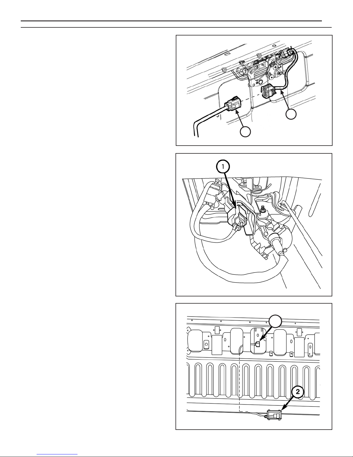
NOTE: If equipped with a power lock actuator, remove
and discard the lock actuator harness.
13. Connect the supplied harness (E) to the camera and
connect the supplied tailgate harness (D) to harness (E).
NOTE: Tape back the lock actuator connector if
vehicle is not equipped with a lock actuator.
14. Connect the lock actuator connector (1) (if equipped).
4
E
D
15. Route tailgate jumper harness (D) through the
tailgate as shown to the tailgate closeout panel (2).
3/11/14
D
K6862043
www.mopar.com
16. Install the actuator rods (2) to the latch control using
the reference marks made during the removal
procedure.
17. Install the tailgate cover and liner (if equipped).
NOTE: If the vehicle is equipped with the tailgate lock
actuator, you must remove and transfer the two
wires from the existing b
connector to the supplied body harness (A)
connector. See graphic for more information.
ody side tailgate
5
18. If equipped with the tailgate lock actuator, remove the
wires (1, 2) from the existing tailgate connector (3),
then discard the existing tailgate connector.
19. Remove the terminal plugs from cavities 7 and 8 in
the supplied body harness connector (A).
20. Transfer the P237 DG/TN wire removed from cavity
7 of the original connector and transfer into cavity 7
of the supplied harness connector.
21. Transfer the P235 LG/TN wire removed from cavity 8
of the original connector and transfer into cavity 8 of
the supplied harness connector.
3/11/14
K6862043
www.mopar.com
NOTE: When routing the body harness, make sure
the harness cannot contact any moving parts
or hot exhaust.
22. Route supplied body harness (A) from the back of
the vehicle to the front as shown, following the
existing harness on the driver side. Tie straps must
be used every 150mm to secure harness (A) to
the existing vehicle harness.
23. Remove the ground bolt (2) located on the left
fender next to the Power Distribution Center (PDC).
6
24. Connect the black wire in the supplied body harness
(A) to the ground location on the fender.
25. Install the ground nut (2). Tighten the ground bolt to
9 N·m (80 in. lbs.).
26. Release the PDC retaining clips (1) and remove the
PDC from the mounting bracket.
A
2
1
3/11/14
1
K6862043
www.mopar.com
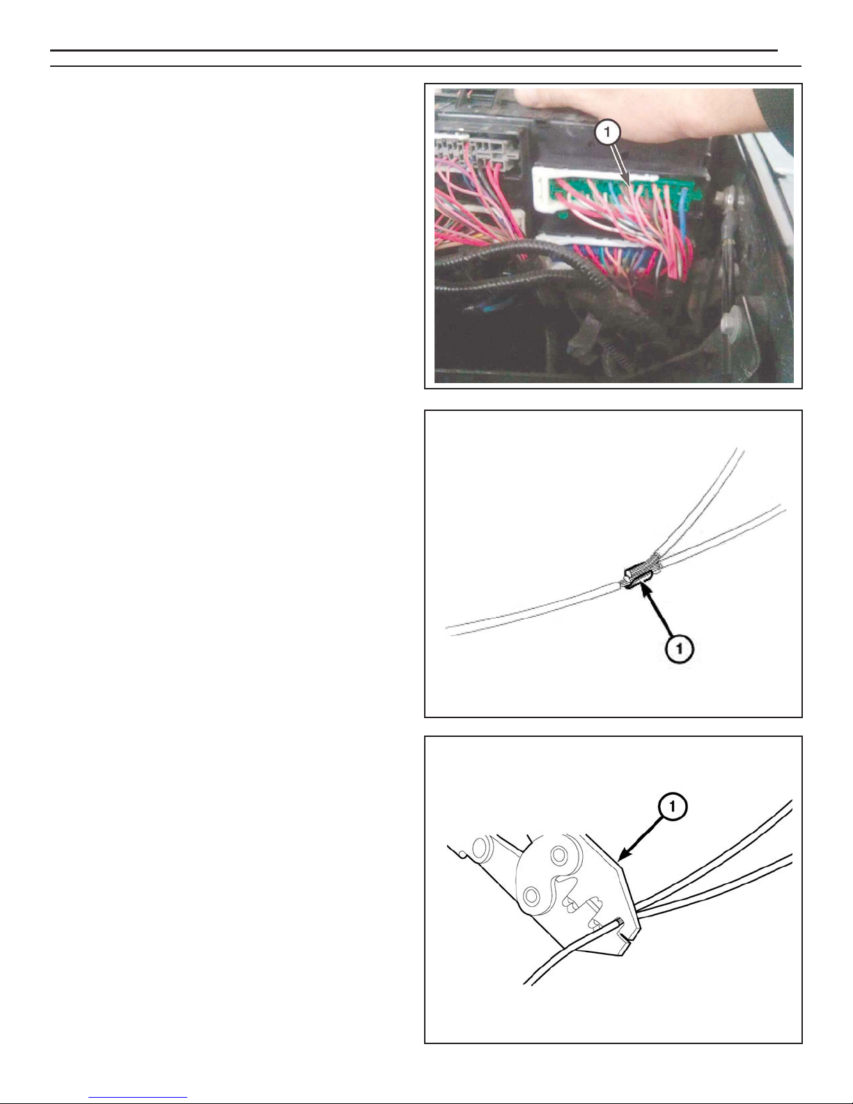
27. Rotate the PDC to gain access to the underside of
the PDC.
28. Locate circuit F923 (PK/YL) at cavity 13 (1) on the
underside of the PDC.
29. Splice the red wire from the supplied body harness
(C) to the PK/YL (F923) wire at cavity 13 of the PDC
(Splice and solder new wire to the original wire
using the soldering procedure in steps 30 thru 33).
30. Place the strands of the wires overlapping each
other inside of the splice clip (1).
7
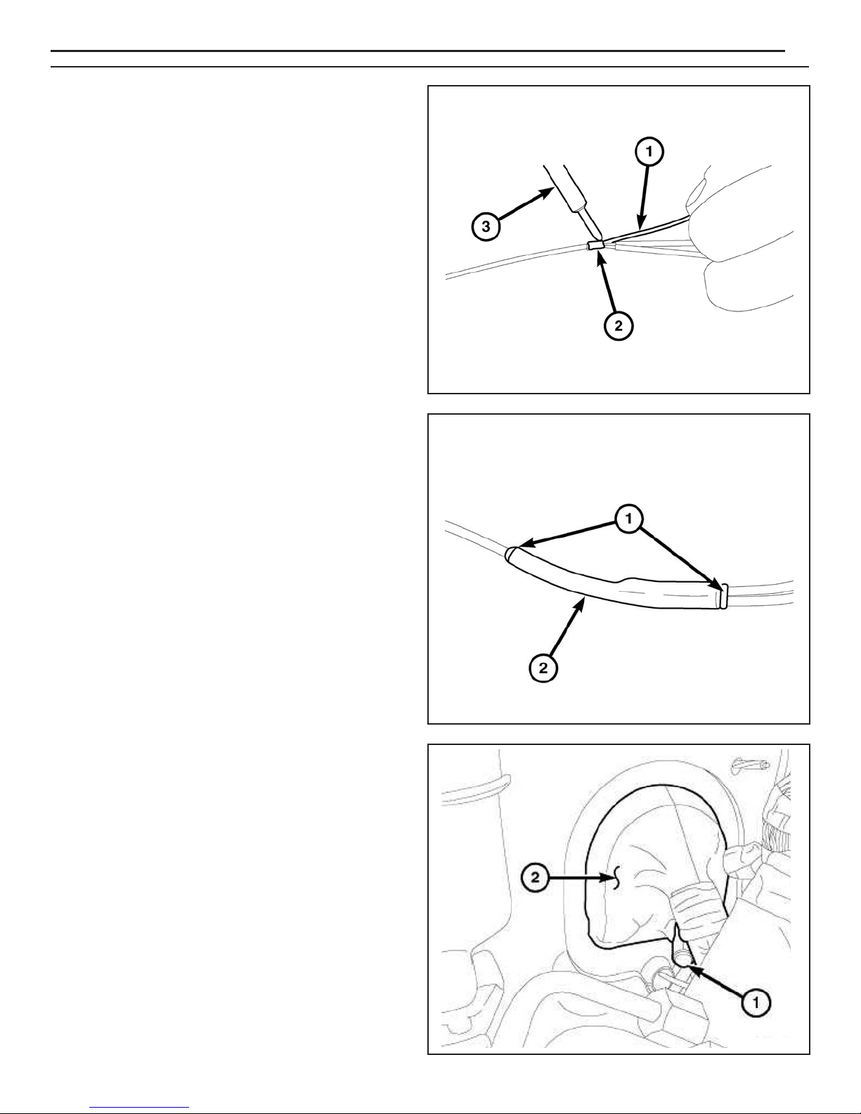
31. Using Mopar
the splice clip and wires together.
® crimping tool (1) or equivalent, crimp
3/11/14
K6862043
www.mopar.com
32. Solder (3) the connection (2) together using rosin
core solder (1).
33. Center the heat shrink tubing (2) over the solder joint
and heat using a heat gun. Heat the joint until the
tubing is tightly sealed and sealant (1) comes out of
both ends of the tubing.
8
34. Install the PDC to its original mounting location by
pressing it back into place.
35. Route the remaining supplied body harness (A) to
the body grommet on driver side bulkhead.
36. Cut the end off the dash panel grommet nipple (1)
hanging off the bottom side of the body harness
near the brake booster.
37. Route the backup camera harness through the dash
panel grommet nipple.
38. Apply MoparT RTV 82300234 around the grommet
nipple.
3/11/14
K6862043

39. Continue to route the supplied body harness (A) to
the driver kick panel area.
40. Insert wires into supplied connector (taped to
harness in polybag) as listed below:
Cavity A GRY/BLU
Cavity B YEL
Cavity C - GRN
Cavity D GRY/ORG
Cavity E Bare
Cavity F - BLU
41. Release and remove connector C5 (1) from the
Body Control Module (BCM).
www.mopar.com
9
42. Remove the housing (2) to gain access to the
terminal blocks (1).
3/11/14
K6862043
www.mopar.com
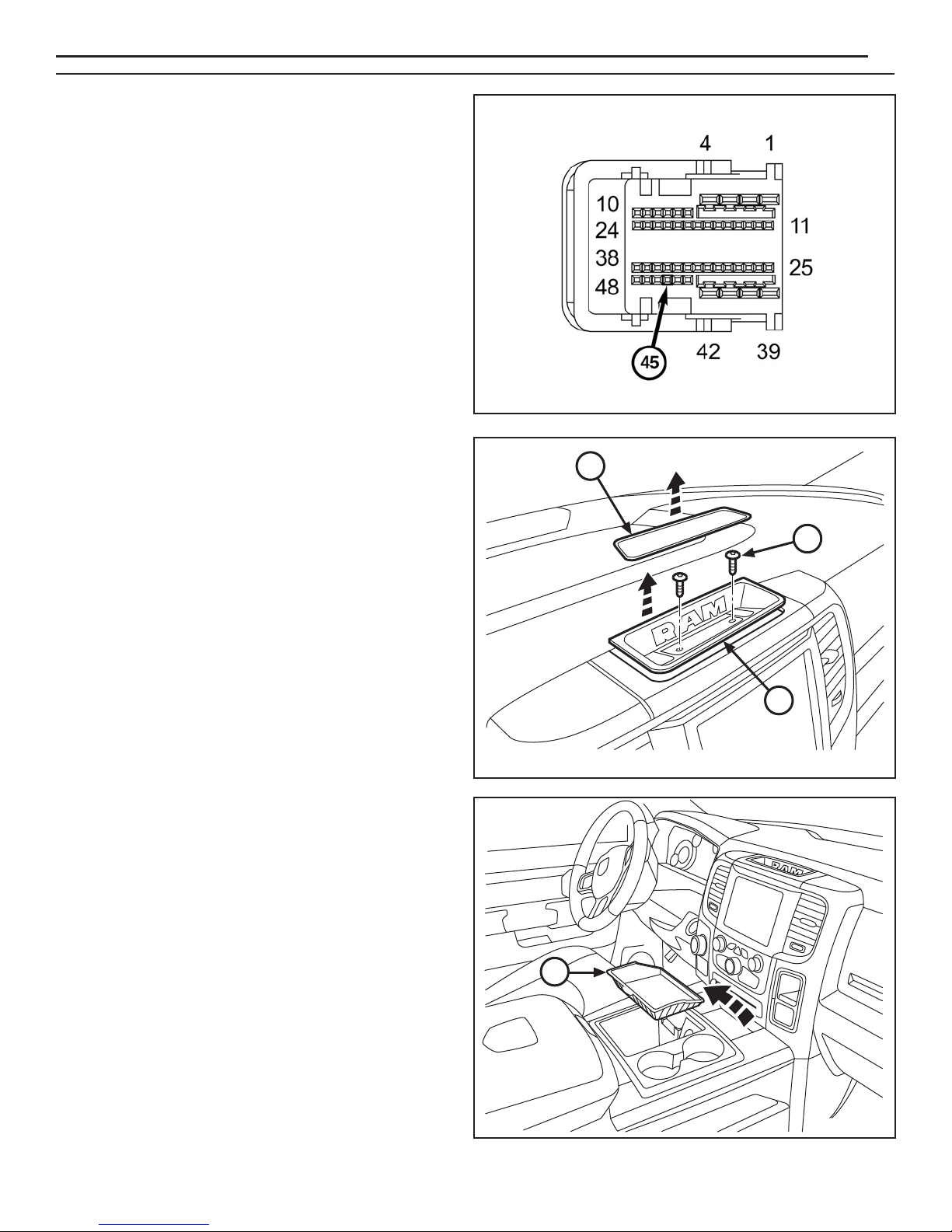
NOTE: Connector C5 front view is shown.
43. Insert the purple wire from supplied harness (A)
into connector C5 cavity 45. If the cavity is already
populated, cut the terminal off the purple wire and
splice the purple wire to the ORG/DB wire in cavity 45
(Splice and solder new wire to the original wire using
the soldering procedure in steps 30 thru 33).
NOTE: Yellow wire is not used. Tape back onto harness.
44. Assemble connector C5 and insert back into BCM.
NOTE: Be sure to keep all fasteners for later
reinstallation.
45. Remove the storage tray cover (1) from the top center
area of the dashboard. Remove fasteners (2) from the
storage tray (3). Remove the tray.
10
1
2
46. Remove the storage tray (1) from the front of the
center console.
3
1
3/11/14
K6862043
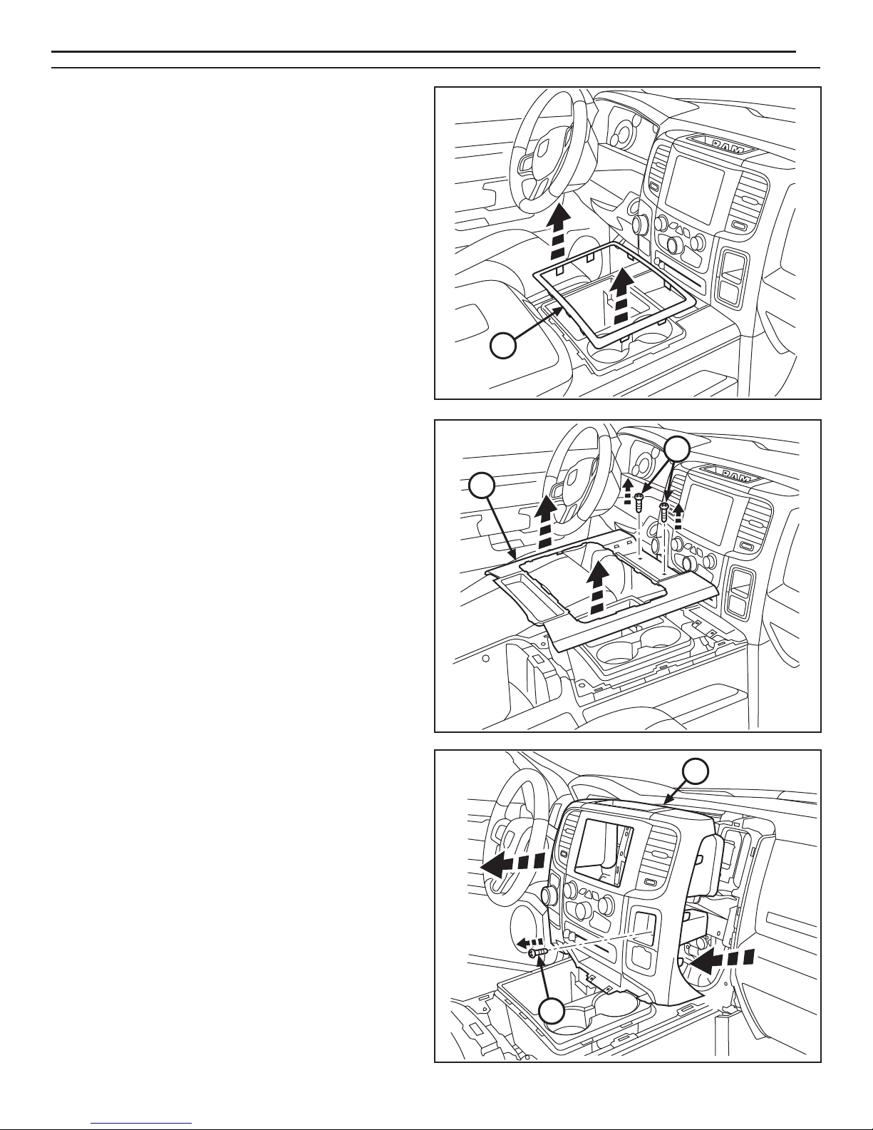
47. Remove the edge trim (1) from the center console
cover panel.
www.mopar.com
11
1
48. Remove fasteners (1) at the front edge of the center
console cover panel (2). Remove the cover panel.
49. Remove fastener (1) from the storage cubby on the
right side of the center dash trim panel. Carefully
disengage all retainer clips and pry off the trim panel (2).
1
2
2
3/11/14
1
K6862043
www.mopar.com
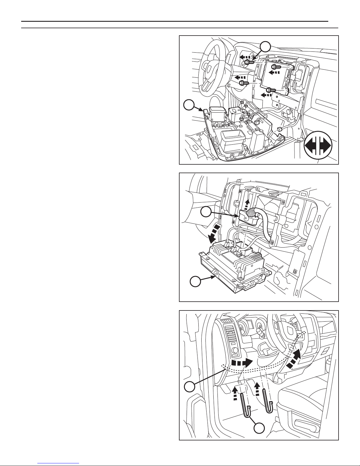
50. Disconnect all plugs from the back of panel (1).
Remove the panel from the vehicle.
51. Remove fasteners (2) from the radio assembly.
52. Remove radio assembly (1) from dash. Unlock the
the 52-way connector (2) at the back of the radio and
disconnect.
12
2
1
53. Route the radio harness (B) under the dashboard and
up to the center stack. Secure harness with cable
ties (H).
NOTE:
than 100mm apart.
Cable ties should be installed no farther
2
1
3/11/14
B
H
K6862043
www.mopar.com
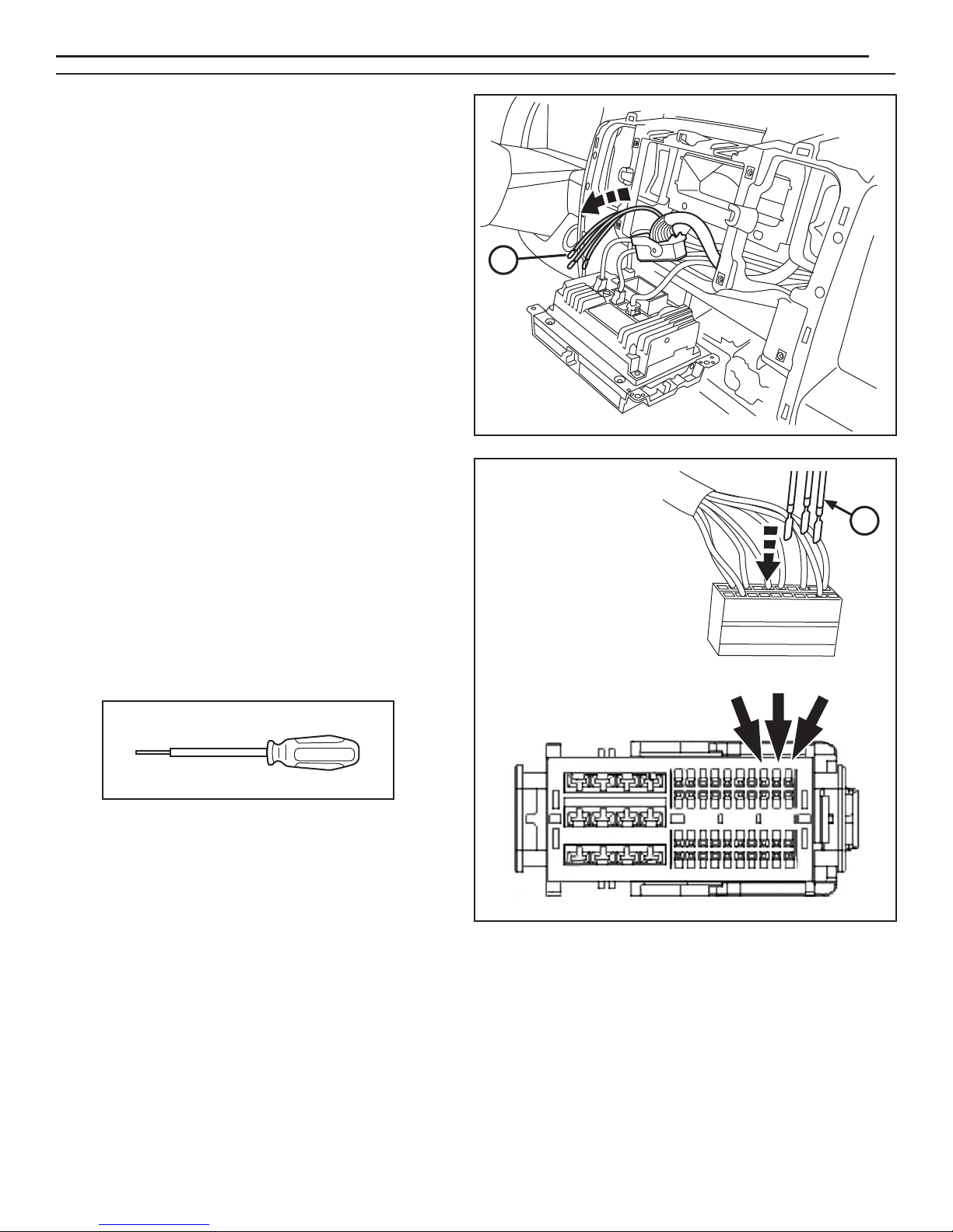
54. Feed the three-prong end of radio harness (B) up into
the center stack and out through the radio opening.
55. If necessary, depopulate the three existing wires
indicated from the connector and tape back onto
the harness. Insert the new wires from the
camera harness as follows:
13
B
B
Cavity 31 GRY/BLU
Cavity 32 GRY/ORA
Cavity 33 - Bare
NOTE: Use Miller 6680 Depopulate Tool to remove wires.
56. Check all wiring and trim all cable ties.
57. Reconnect the battery.
PIN 33
PIN 32
PIN 31
58. Reverse steps 45 through 52, 26, and 3 to reinstall all vehicle components.
59. Follow the Vehicle Configuration Instructions on the next page.
3/11/14
K6862043
 Loading...