

Mopar Journey Installation Manual

1
www.mopar.com
BACKUPCAMERA
JOURNEY
CALLOUTDESCRIPTIONQUANTITY
1Backupcameraharness1
2
3Backupcameraconnector1
4Zipties12
5
6
10mm,15mmSocketand
Ratchet
Feb02,2011K6861161
BackupcameraharnesstoT elematicsGatewayModule
(TGM)connector
Liftgatehandlecarrierwithlicenselampsandbackupcamera
SpliceKit(includes2splicecollarsandshrinktube)
ToolsRequired
CrimpingTool,Mopar®p/n
05019912AAorequivalent
ElectricalSolderingKitHeatGun
1
1
1
2
www.mopar.com
ToolsRequired
PhillipsScrewdriverPowerOutletRemover
10246orequivalent
TrimPanelT ool
TrimStickC4755or
equivalent(1)
ScanT oolT20,T30Torx®Driver
WireStrippers
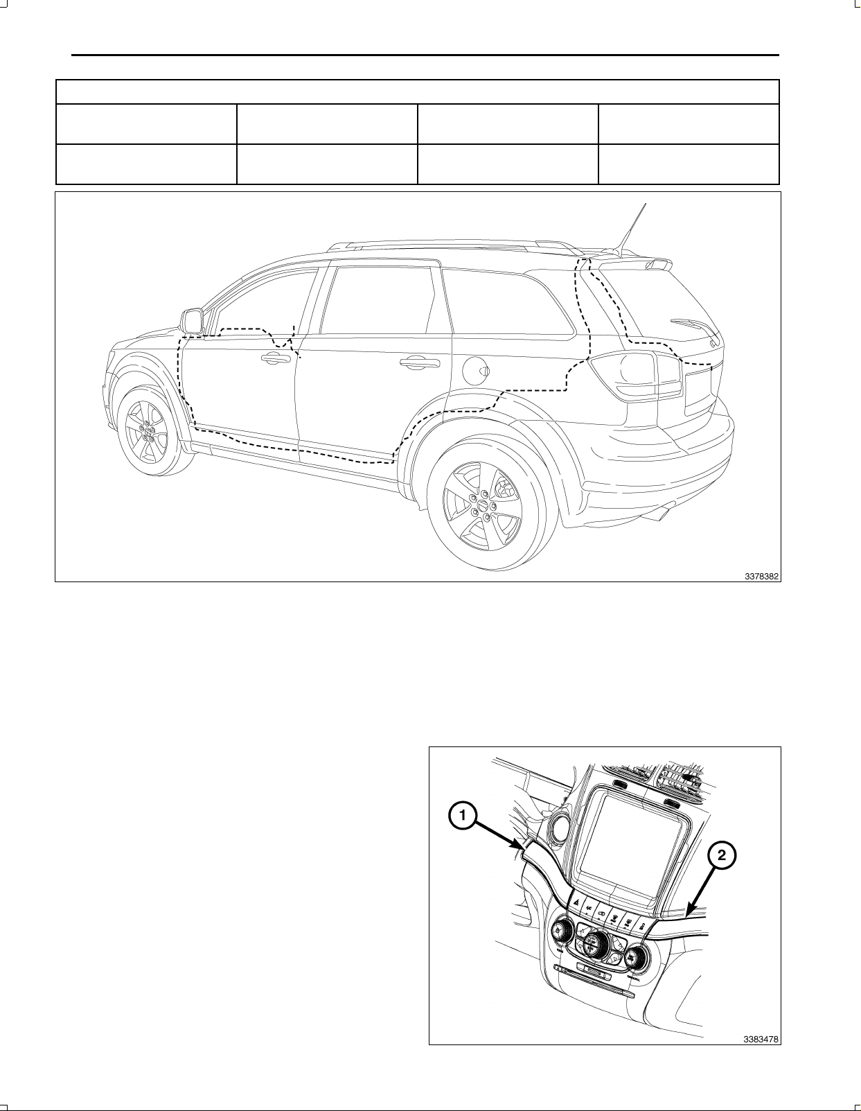
BackUpCameraHarnessRouting
PROCEDURESTEPS:
WARNING:Disabletheairbagsystembeforeattemptinganysteeringwheel,steeringcolumn,orinstrument
panelcomponentdiagnosisorservice.Disconnectandisolatethenegativebattery(ground)cable,thenwait
twominutesfortheairbagsystemcapacitortodischargebeforeperformingfurtherdiagnosisorservice.This
istheonlysurewaytodisabletheairbagsystem.Failuretotaketheproperprecautionsmayresultinaccidental
airbagdeploymentandpossibleseriousorfatalinjury.
1.Disconnectandisolatethebatterynegativecable.
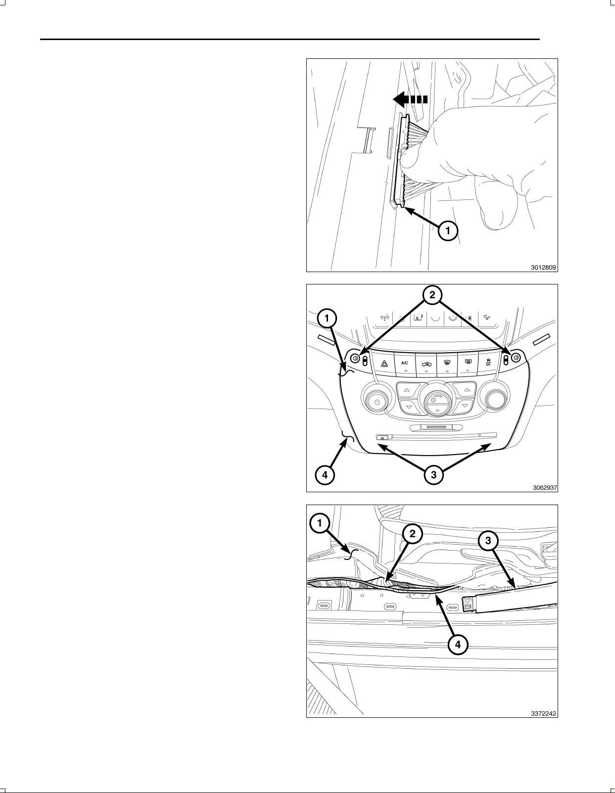
2.UsingtrimstickC4755orequivalent,loosenthe
instrumentpaneltrim(2)locatedrightofthecenter
stackbezelenoughtoaccesstheswitchbank
retainingscrewunderneath.
3.UsingtrimstickC4755orequivalent,removethein
strumentpaneltrim(1)locatedleftofthecenterstack
bezel.
Feb02,2011K6861161

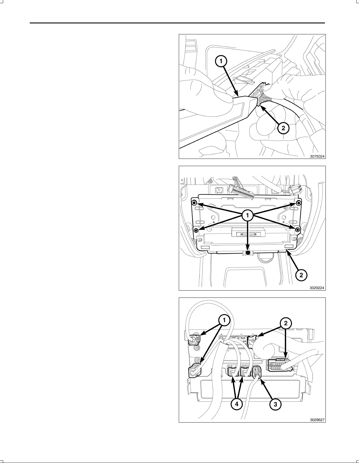
4.Removethescrews(2)thatsecuretheswitchbank
www.mopar.com
(1)totheI/P(4).
NOTE:Onlydisconnecttheswitchbankassembly
wiringharnessconnectorbyfollowingthespecific
stepsfollowingthisstep.
5.UsingatrimstickC4755orequivalent,gentlyprybe
tweentheswitchbankassembly(1)andtheinstru
mentpaneltoreleasethesnapretainers(locatedat
3)thatsecuretheswitchbankassembly(1)tothein
strumentpanelandpullawayfrominstrumentpanel
foraccesstoremovetheconnectorusingthefol
lowingsteps:
CAUTION:Neverpulltheconnectoroutbythewires.
Failuretofollowtheseinstructionswilldamageor
breakthewiresand/orconnector.
CAUTION:Pushthe40wayconnectorinbeforepush
ingonthelockingclip.Failuretofollowtheseinstruc
tionswilldamageorbreaktheconnectorlockingclip.
3
6.Pushinonthe40wayconnector(1)oftheswitchbank
assembly.
7.Gentlypushdownontheconnectorreleaselock(1).
Feb02,2011K6861161
4
www.mopar.com
8.UsingatrimstickC4755orequivalent(1),gentlypry
ononesideoftheconnector(2)toremove.
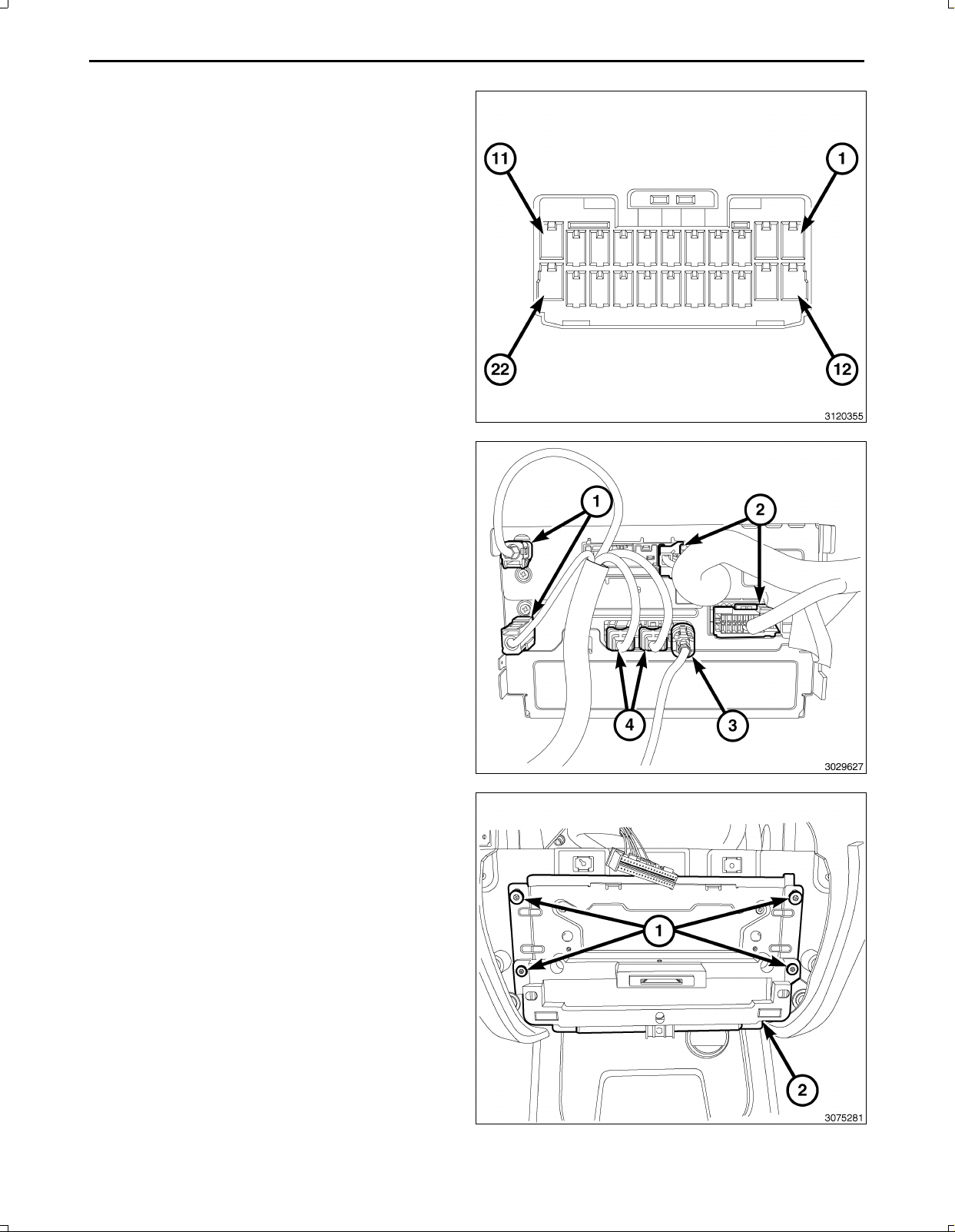
9.Removetheretainers(1)fromtheTelematicsGate
wayModule(TGM)(2)andpulloutfarenoughtoac
cesstheconnectorsonthebackoftheTGM.
CAUTION:Pullingtheantennacablestraightoutofthe
radiowithoutpullingonthelockingantennaconnec
torcoulddamagethecableorradio.
10.Disconnecttheantenna(s)(1),RFHUBandUCIca
bles(4),videocable(3)andwiringconnectors(2)from
theTGM.
11.RemovetheTGMfromthevehicle.
Feb02,2011K6861161
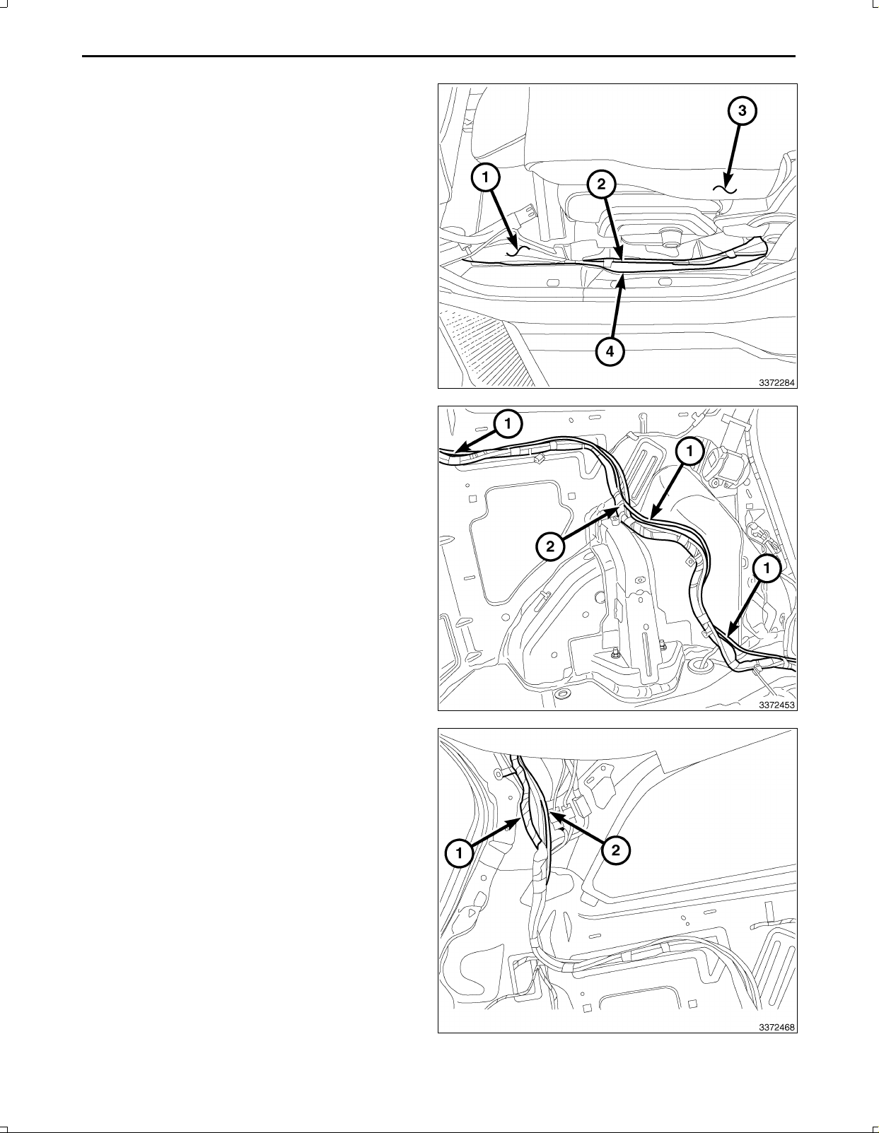
NOTE:Seatsremovedforclarity.
www.mopar.com
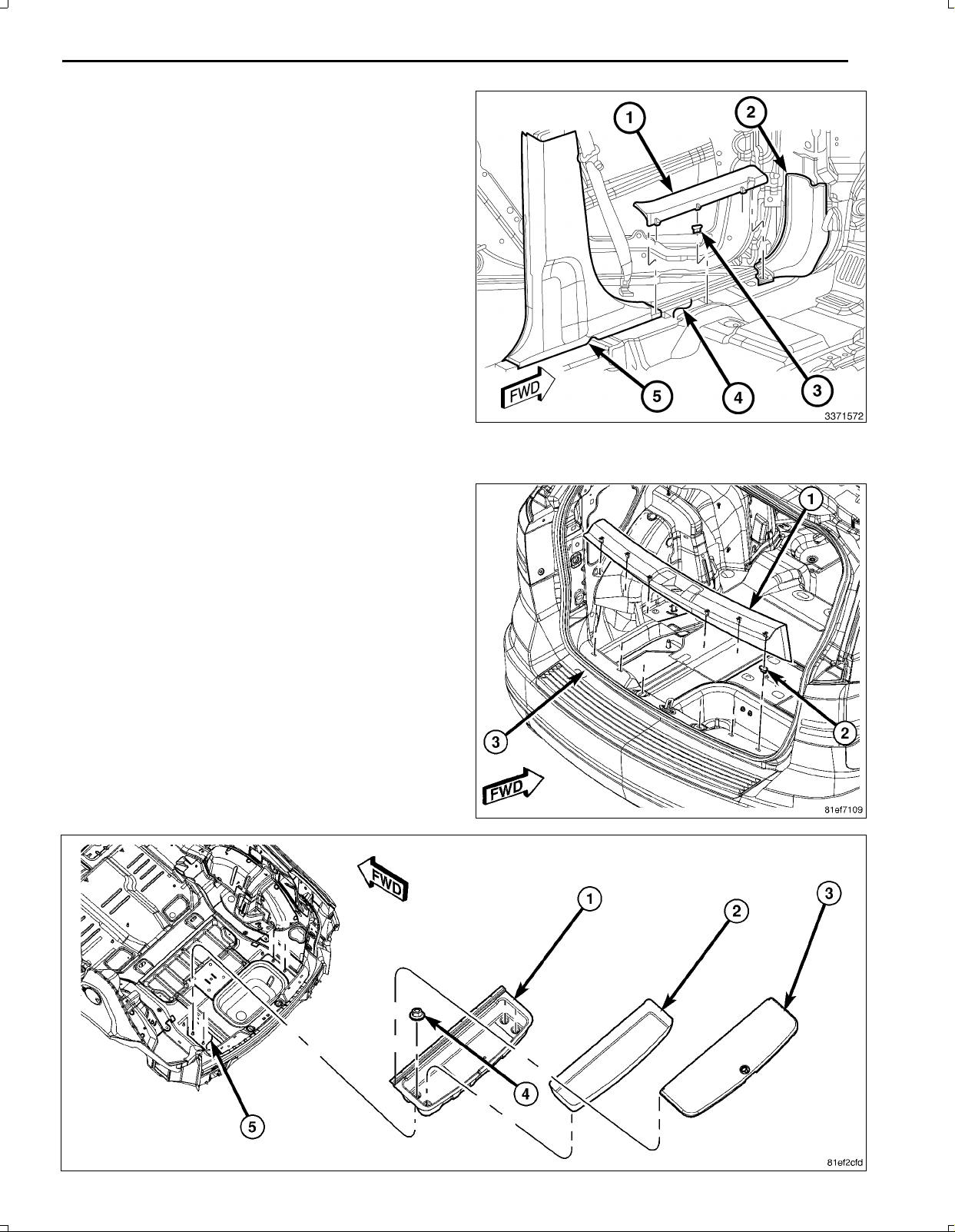
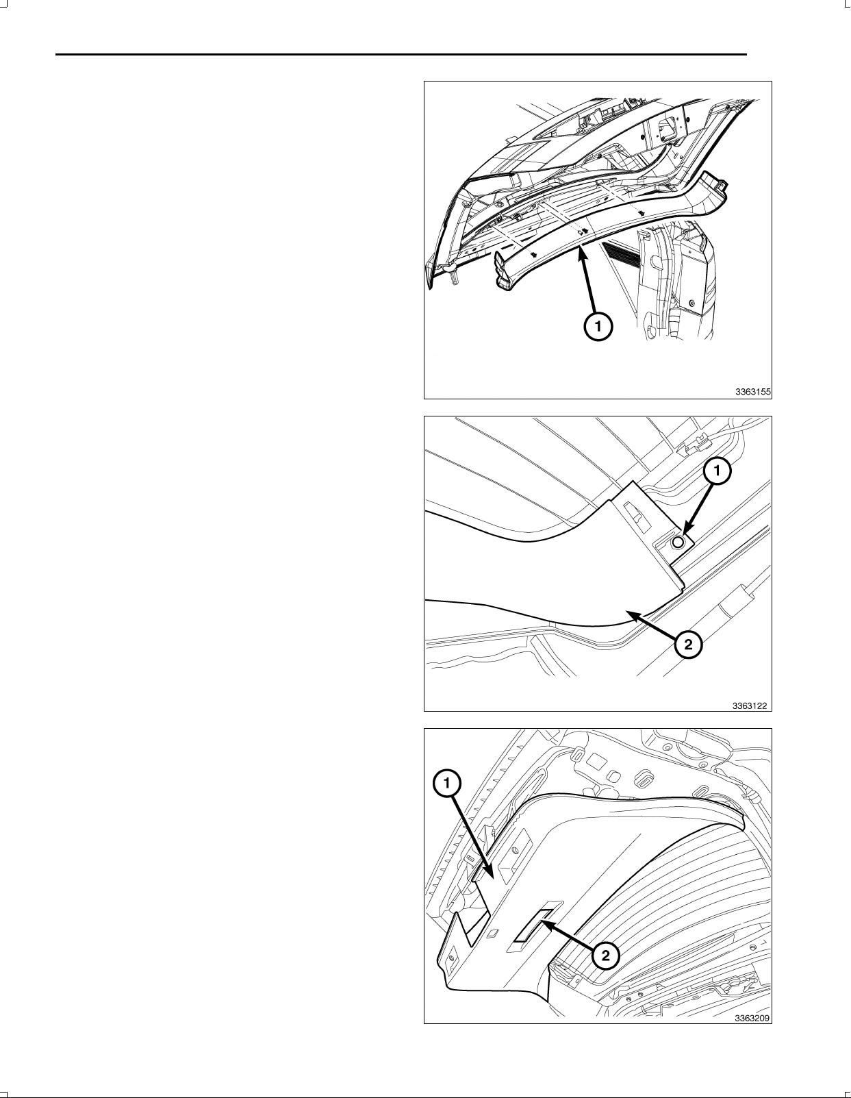
12.UsingtrimstickC4755orequivalent,disengageclips
holdingdoorsillscuffpanel(1).
13.Startingattheforwardendofthedoorsillscuffplate
(1),pullupwardonthesillscuffplateinordertodis
engagetheclips(3)attachingsillscuffplatetodoor
openingflange(4).
14.RemoveLFdoorsillscuffplate(1)fromvehicle.
15.RemovetheLRdoorsillscuffplate(notshown)the
sameasthefront.
16.UsingtrimstickC4755orequivalent,disengage
clipsholdingtheLHkickpanel(2)andremovethe
kickpanel.
NOTE:ItisnotnecessarytoremovetheBpillartrim,
onlyloosenforaccesstoroutethebackupcamera
wiringharness.
17.UsingtrimstickC4755orequivalent,disengageclips
holdingthelowerportionoftheBpillartrim(5)andpullinwardtoloosenenoughtoroutethebackupcamerawiring
harness.
18.Opentheliftgate.
19.UsingtrimstickC4755,carefullyprytheliftgatesill
plateoutdisengagingtheretainingclips.
20.Removetheliftgatesillplatefromthevehicle.
5
Feb02,2011K6861161
6
www.mopar.com
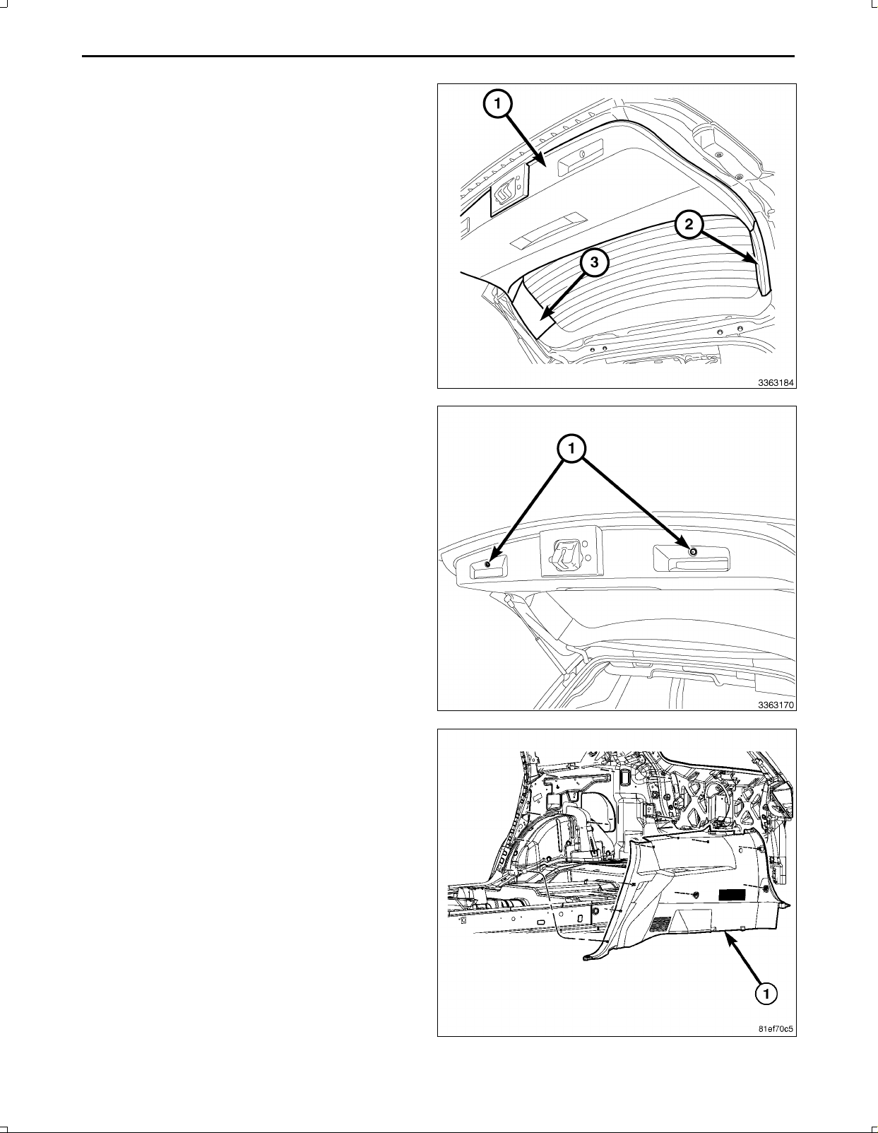
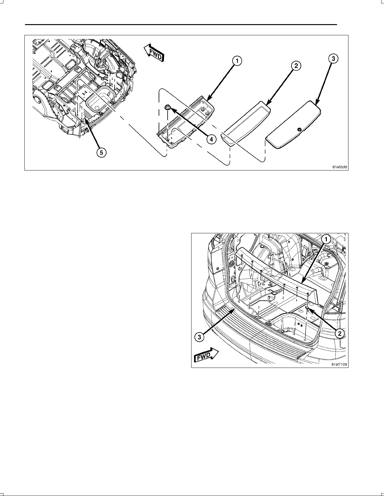
NOTE:Storagebinwiththirdrowseatshown,withoutthirdrowseatsimilar.
21.Ifequippedwithathirdrowseat,removetheretainersontheseatbackgaphidertotherearstorageboxandopen
thestorageboxlid(3).
22.Ifequipped,removethematorloadfloorassemblycoveringthestoragebox.
23.Ifequipped,removethestorageboxliner(2).
24.Removethefourstorageboxmountingfasteners(4).
25.Removethestoragebox(1)fromthevehicle.
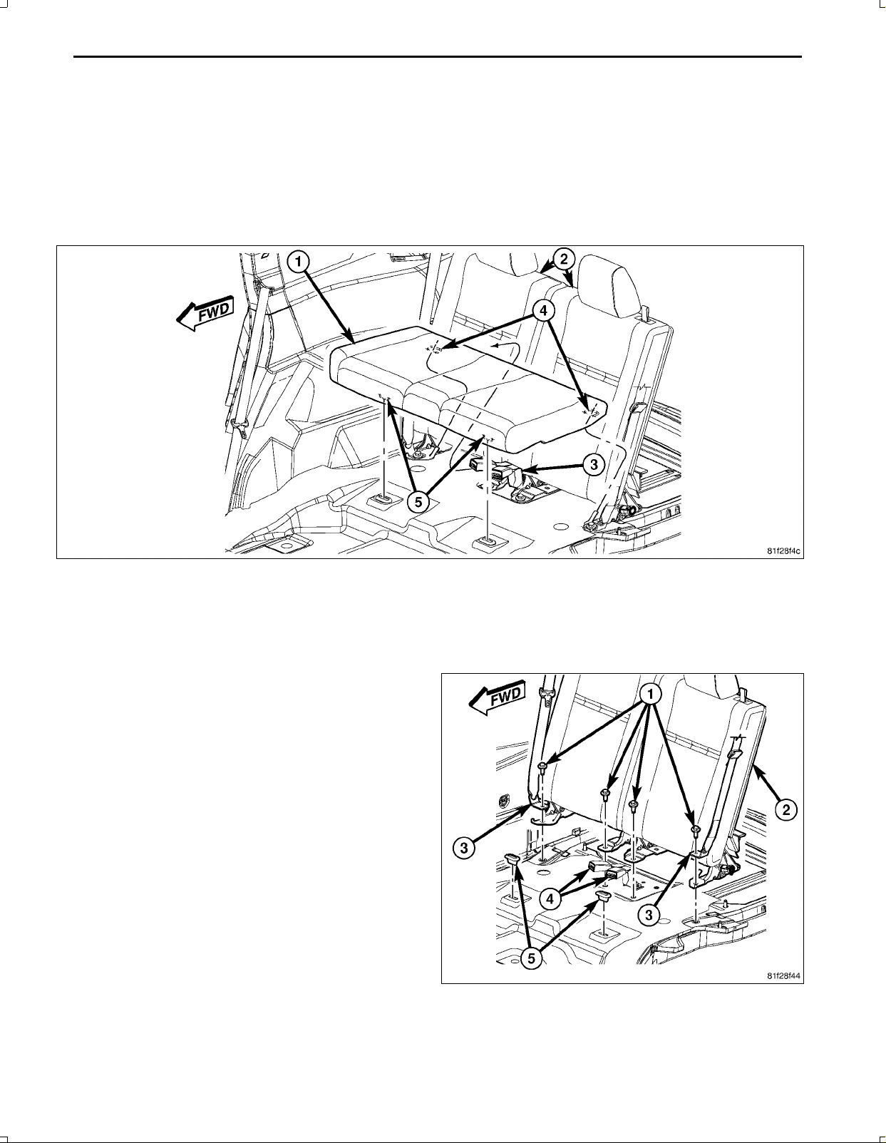
26.Liftfrontedgeofthethirdrowseatuntilretainers(5)disengage.
27.Withthehelpofanassistant,carefullypryuponthehooks(4)whiletheseatcushionisbeingpressedtowardsthe
seatback.
28.Whileliftinguponthehooks(4),pulltheseatcushion(1)outtowardsthefrontofthevehicleandremovetheseat
cushion.
29.Removetheseatbackfrontmountingfasteners(1).
Feb02,2011K6861161
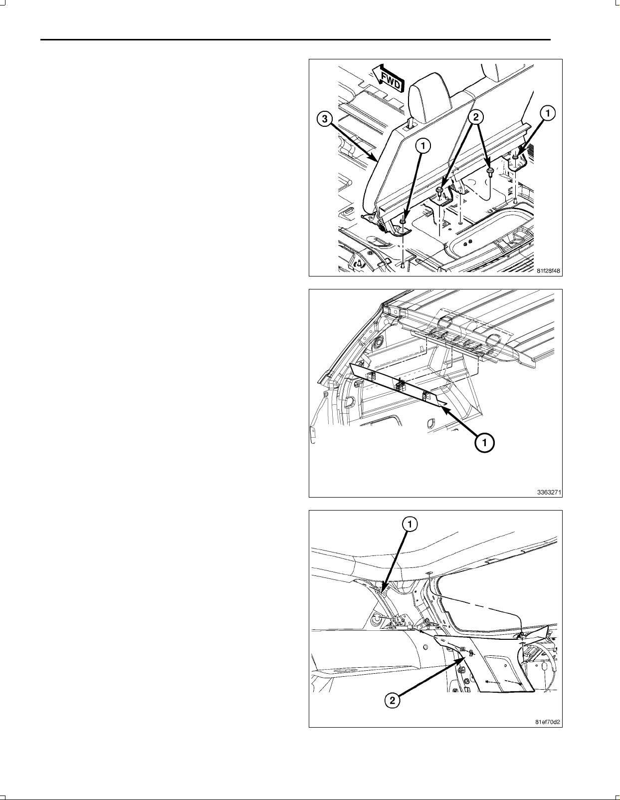
30.Removetherearseatbackmountingfasteners(1,2).
www.mopar.com
31.Removetheseatbackfromthevehicle.
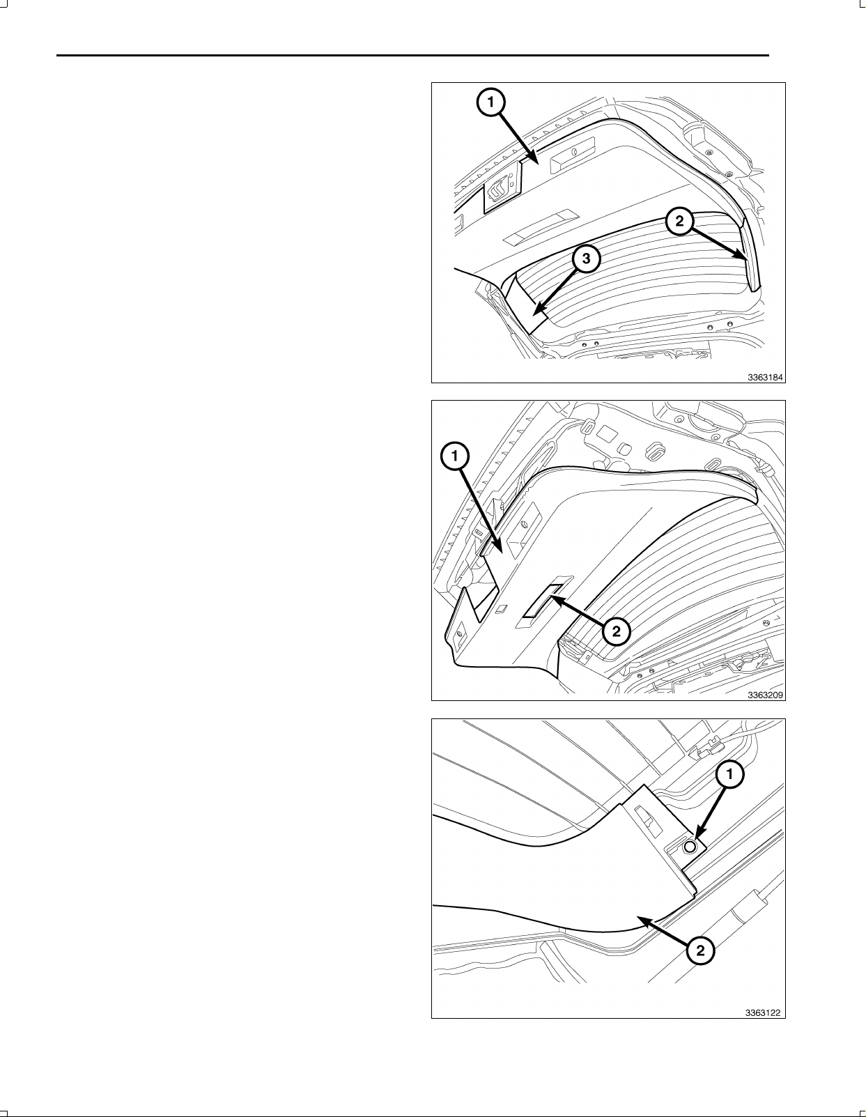
32.Removetherearheadertrimpanel(1)bycarefully
pullingdownonthetrimtodisengagetheretainers.
7
33.RemovetheDpillartrimaccessholecoversandre
movethemountingfasteners.
34.UsingtrimstickC4755,carefullyprytheDpillartrim
(2)outdisengagingtheretainingclips.
35.RemovetheDpillartrim(2)fromthevehicle.
Feb02,2011K6861161
8
www.mopar.com
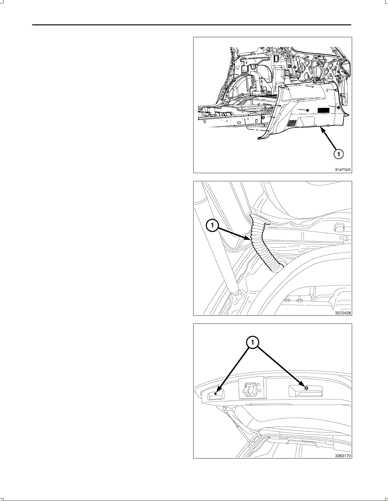
36.Removethequartertrimpanelmountingfasteners.
37.UsingtrimstickC4755,carefullyprythequartertrim
panel(1)outdisengagingtheretainingclips.
38.Carefullyremovethequartertrimpanel(1)frombe
tweenthebodyandthesecondrowseat.
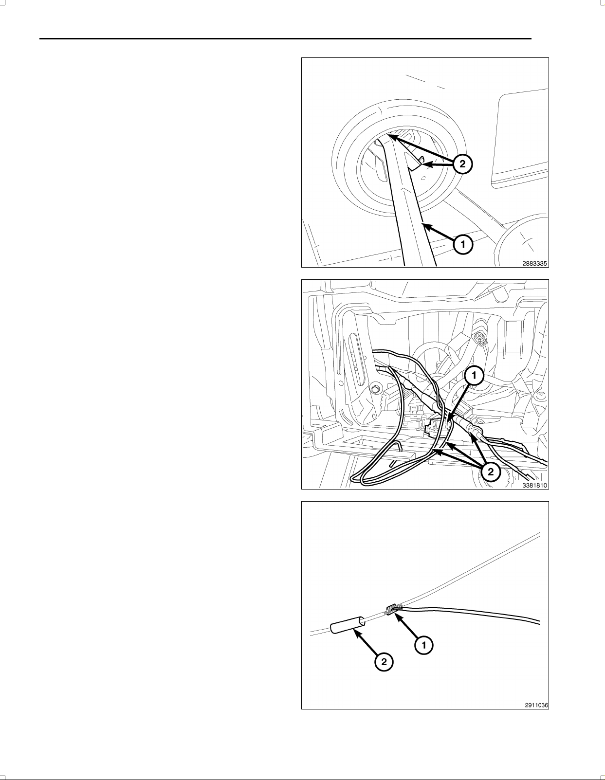
39.Disconnectthewiringharnessgrommet(1)fromthe
bodyandtheliftgate.
40.Opentheliftgate.
41.Removethetwolowerscrews(1).
Feb02,2011K6861161
NOTE:Thesidetrimpanelscanberemovedincon
www.mopar.com
junctionwiththelowerliftgatetrimpanel.
42.UsingtrimstickC4755orequivalent,disengagethe
sidetrimpanel(2,3)retainingclips.
43.UsingtrimstickC4755orequivalent,pryaroundthe
perimeterofthelowertrimpanel(1)todisengagethe
retainingclips.
44.Positionthelowertrimpanel(1)slightlyawayfrom
thedooranddisconnectthewiringharnessconnector
fromtheliftgatelamp(2).
45.Removethelowertrimpanel(1).
9
46.Usingasmalltrimtoolorequivalent,separatethe
pushpinfasteners(1)fromtheuppertrimpanel(2).
Repeatontheoppositeside.
Feb02,2011K6861161
10
www.mopar.com
47.UsingtrimstickC4755orequivalent,pryaroundthe
perimeteroftheuppertrimpanel(1)todisengagethe
retainingclipsandremovethetrimpanel.
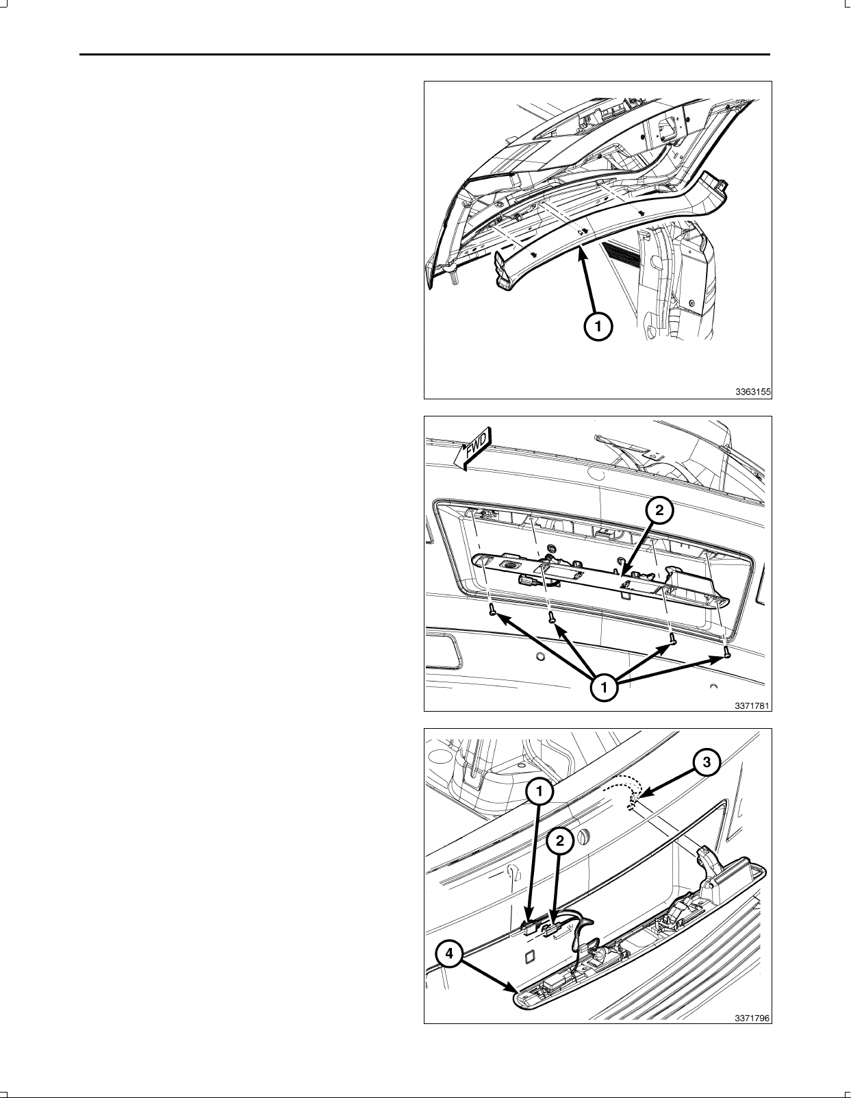
NOTE:Afterremovingtheretainers(1)therearere
tainingtabsthatneedtobereleasedforremovingthe
lightbar.
48.Removethefourretainers(1)holdingthelightbar(2)
totheliftgate.
49.Usingatrimstickorequivalent,releasethelightbar
fromtheretainingclips.
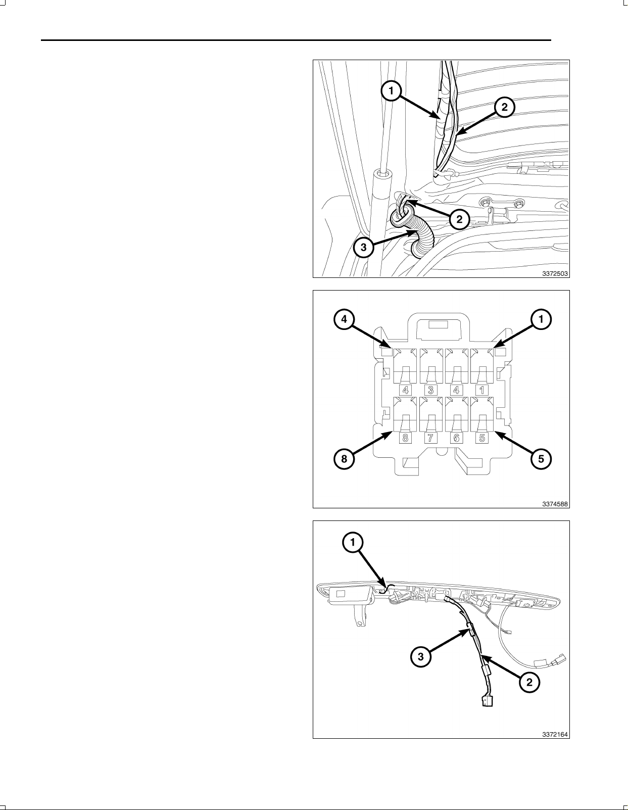
50.Disconnecttheswitchandlampelectricalharness
connectors(1,2)fromthelightbar(4)asnecessary.
51.Disconnecttheliftgatereleasecable(3)fromthelight
bar/handleanddiscardthelightbar.
Feb02,2011K6861161
52.Removethe12VignitionpoweroutletfromtheI/P
www.mopar.com
lowerbinareaasfollows:
a.Lookinsideandnotepositionoftheretainingbosses
(2).
b.InsertPowerOutletRemover10246(1),orequivalent
intotheretainingbosses(2)ofthepoweroutlet.
c.Pulloutthebasethroughthemountingringbygently
rockingthetool.
d.Disconnecttheharnessfromthepoweroutletandset
theoutletaside.
e.Pullthe12Vignitionpoweroutletwiringharnesscon
nectorthroughtheopeninginthebackofthecenter
stackareaforsplicing.
NOTE:TheI/Pendofthebackupcameraharness(2)
hasthetwowireswithoutterminalendsforsplicing
tothe12Vignitionpoweroutletconnector(1).
11
NOTE:Ensurewhenroutingthewireharnessnotto
damagethewireterminals.
53.Feedthebackupcamerawiringharness(2)fromthe
LHsideoftheI/Pneartheparkbrakepedaloverthe
brakepedalsledandthroughthelowerI/Pandintothe
centerI/Pstackareaforconnectingtothe12Vigni
tionpoweroutletwiringharnessconnector(2)andthe
TGM.Securetothevehicleharnesswithtiestraps.
54.Removeenoughoftheinsulatingtapefromthewires
ofthe12Vignitionpoweroutletwiringharnesscon
nector(1)tospliceintothetwowires.
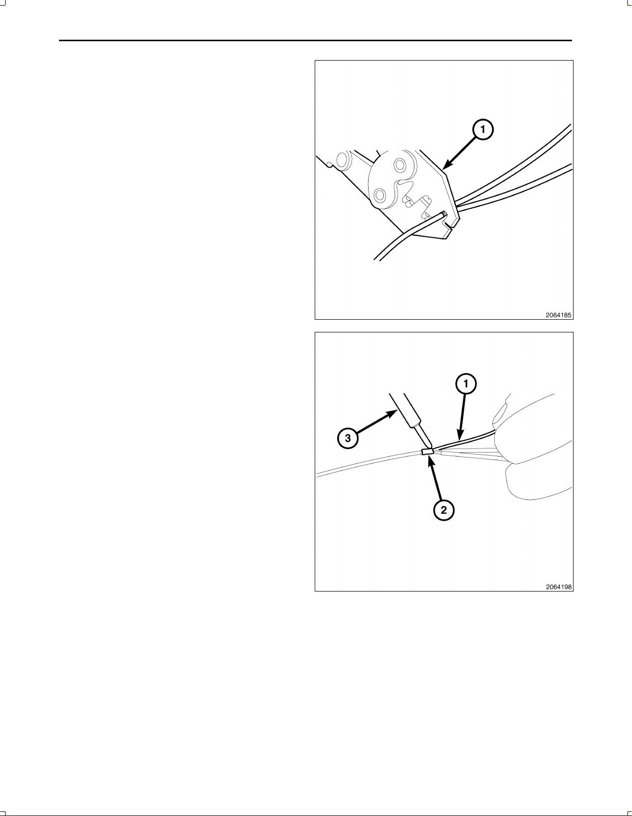
55.Preparetocrimp/splicethebackupcamerapowerwire
(PK/OR)tothe(DB/PK)ofthe12Vignitionpowerout
letwiringharnessconnectorasfollows:
a.Cutthe12VignitionpoweroutletDB/PKwire.
b.Remove13mm(0.5in.)ofinsulationfromeach
wirethatneedstobespliced.
c.Placeapieceofadhesivelinedheatshrinktubing
(2)ononesideofthewire.Makesurethetubing
willbelongenoughtocoverandsealtheentire
repairarea.
d.Placethestrandsofwireoverlappingeachother
insideofthespliceclip(1).
Feb02,2011K6861161
12
www.mopar.com
56.Usingcrimpingtool(1),Mopar®p/n05019912AAor
equivalent,crimpthespliceclipandwirestogether.
CAUTION:Donotuseacidcoresolder.
57.Usingasoldertool(3),soldertheconnection(2)to
getherwithrosincoresolder(1).
Feb02,2011K6861161
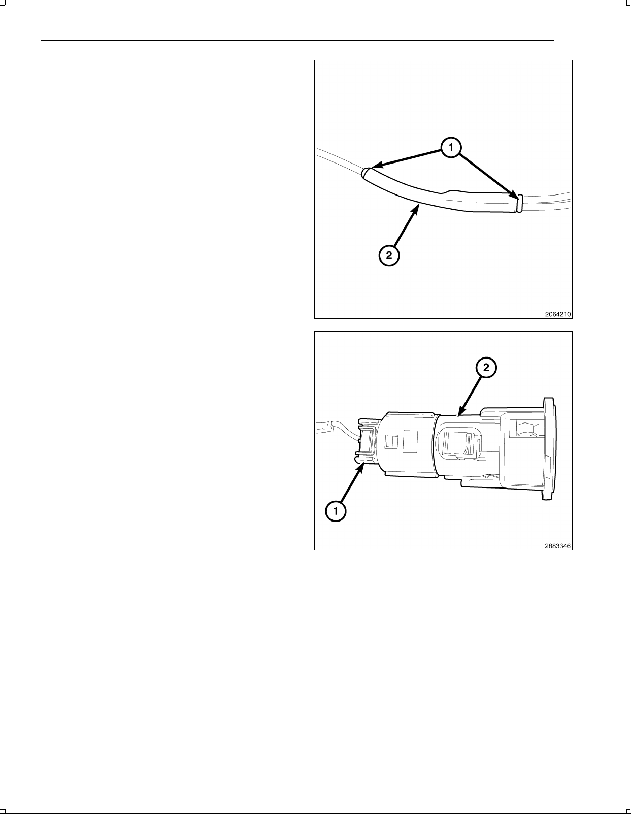
58.Centertheheatshrinktubing(2)overthesolderjoint
www.mopar.com
andheatusingaheatgun.Heatthejointuntilthetub
ingistightlysealedandsealant(1)comesoutofboth
endsofthetubing.
59.Crimp/splicethebackupcameragroundwire(BK)to
theground(BK)ofthe12Vignitionpoweroutletwiring
harnessconnectorasabove.
13
60.Installthe12Vignitionpoweroutletasfollows:
a.Feedthe12Vignitionpoweroutletwiringharnesscon
nector(1)throughtheopeninginthebackofthecenter
stackareaandconnecttothereceptacle(2).
b.Alignthesplinesontheoutsideofthepoweroutletre
ceptaclebaseconnectorreceptaclewiththegrooveson
theinsideofthemount.
c.Installthepoweroutletintothepanelbypressingfirmly
onthepoweroutletreceptaclebaseuntiltheretaining
bossesofthemountarefullyengagedintheirrecepta
cles.
Feb02,2011K6861161
14
www.mopar.com
NOTE:Theremayalreadybea22pinconnectorcon
nectedtotheTGM.Usethatoneanddiscardtheone
suppliedinthekit.
61.BackouttheconnectorwirelockingtabfromtheTGM
harnessconnector3.
62.InsertthecameraharnesswiresintoTGMharness
connector3asfollows:
a.Signalwire(GY/LB)cavity15
b.Returnwire(GY/OR)cavity16
c.Shieldwire(Bare)cavity17
63.Connecttheantenna(s)(1),RFHUBandUCIcables
(4),videocable(3)andwiringconnectors(2)tothe
TGM.
NOTE:Makesurethe40wayconnector(1)ofthe
switchbankassemblyispositionedabovethe
TGMforaccesswhenconnectingtheswitchbank
assembly.
64.PositiontheTGM(2)andinstalltheretainingscrews
(1)totheTelematicsGatewayModule(TGM)(2).
Feb02,2011K6861161
65.Carefullyconnectthe40wayconnector(1)ofthe
www.mopar.com
switchbankassembly.
66.PositiontheswitchbankintheI/Pandpressevenly
theengagethetwolowerclips(3).
67.Install,andtightenthetwoscrews(2)thatsecurethe
switchbank(1)totheI/P(4).
68.InstalltheI/Ptrimtotheleftandrightoftheswitch
bank.
15
NOTE:RoutingundertheI/Pshouldbeabovethe
brakepedalsledandsecuredtoeliminatepossible
interferencewithallpedalmovement.Routing
underthekickpanelshouldbesecuredtoeliminate
possibleinterferencewithallpedalmovement.
69.Routethebackupcamerawireharnessfromunderthe
LHsideoftheI/P(abovethebrakepedalsled)behind
theLFkickpanelandsecuretothevehicleharness
withtiestraps.
70.Routethebackupcamerawireharness(4)withthe
vehiclewiringharness(2)undertheedgeofthecarpet
(1)belowtheLFdoorscuffplateandbelowtheBpillar
lowertrim(3).Attachtothevehiclewiringharness(2)
withtiestrapswherenecessary.
Feb02,2011K6861161
16
www.mopar.com
71.Routethebackupcamerawireharness(4)underthe
edgeofthecarpet(1)belowtheLRdoorscuffplate
andaroundtheedgeofthesecondrowseat(3)tobe
routedunderthequartertrimpanel.Attachtothevehi
clewiringharness(2)withtiestrapswherenecessary.
72.Routethebackupcamerawireharness(1)withthe
bodywiringharness(2)alongthequarterpanel.At
tachtothevehiclewiringharness(2)withtiestraps
wherenecessary.
73.Routethebackupcamerawireharness(2)withthe
bodywiringharness(1)uptheDpillarandthoughthe
bodyaccessholewiththeliftgateharness.Attachto
thevehiclewiringharness(1)withtiestrapswhere
necessary.
Feb02,2011K6861161
74.Routethebackupcamerawireharness(2)thoughthe
www.mopar.com
liftgatewireharnessgrommet(3)withtheliftgatehar
ness(1)tothepointofconnectingtothebackupcam
eraconnectorfromthenewlightbar.Attachtotheve
hiclewiringharness(1)withtiestrapswhereneces
sary.
75.Backouttheconnectorterminallockingtabfromthe
backupcameraconnector.
76.Insertthebackupcameraharnesswiresintobackup
cameraconnectorasfollows:
a.12Vignitionpowerwire(PK/OR)cavity2
b.Signalreturnwire(GY/OR)cavity3
c.Signalwire(GY/LB)cavity4
d.Shieldwire(Bare)cavity7
e.Groundwire(BK)cavity5
17
77.Preparethelightbar(1)forinstallationbytapingthe
licenselampconnector(3)tothebackupcamerahar
ness(2).
Feb02,2011K6861161
18
www.mopar.com
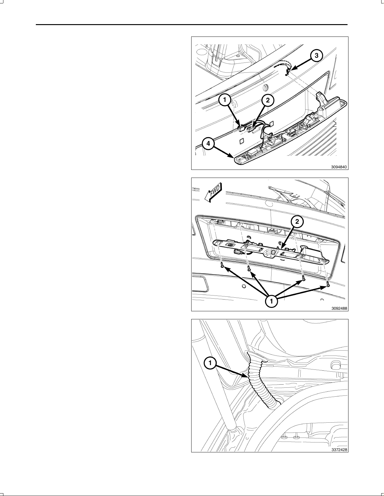
78.Positionthelightbar(4)andconnecttheliftgatere
leasecable(3)tothelightbar(4).
NOTE:Usethevehiclelicenselampconnectorandnot
theoneonthebackupcameraharness.
79.Connecttheelectricalconnectors(1,2)tothebackup
camera,lightsandswitchifequipped.
80.Installthelightbar(2)totheliftgate.
81.Installthelightbarretainingscrews(1)totheliftgate.
82.Seattheliftgateharnessgrommet(1)ontheliftgate
andthebody.
Feb02,2011K6861161
83.Alignthetrimpanel'sretainingclipstotheopenings
www.mopar.com
intheliftgate,handtaparoundtheperimeterofthe
uppertrimpanel(1)toengagetheretainingclips.
84.Installthepushpinfasteners(1)totheuppertrimpanel
(2).Repeatfortheoppositeside.
19
NOTE:Thesidetrimpanelscanbeinstalledincon
junctionwiththelowerliftgatetrimpanel.
85.Positionthelowertrimpanel(1)andconnectthe
wiringharnesstotheliftgatelamp(2).
Feb02,2011K6861161
20
www.mopar.com
86.Alignthetrimpanel'sretainingclipstotheopeningsin
theliftgate,handtaparoundtheperimeterofthelower
trimpanel(1)andthesidetrimpanels(2,3)toengage
theretainingclips.
87.Installthetwolowertrimpanelscrews(1).
88.Carefullypositionthequarterpanelbetweenthebody
andthesecondrowseat.
89.Aligntheretainingclipsandhandtaptoengage.
90.Installthequartertrimpanelmountingfasteners.
Feb02,2011K6861161
91.PositiontheDpillartrim(2),aligntheretainingclips
www.mopar.com
andhandtaptoengage.
92.InstalltheDpillartrimmountingfastenersandaccess
holecovers.
93.Positiontherearheadertrimpanel(1)andhandtap
tosecuretheretainingclips.
21
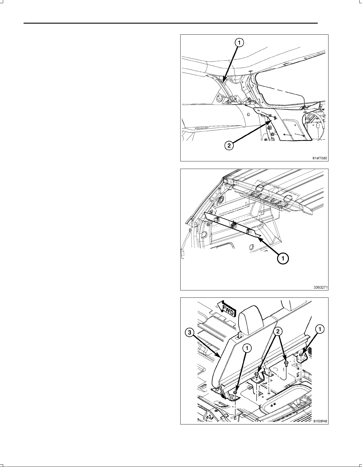
94.Ifequippedwithathirdrowseat,placetheseatback
intoposition.Makesurethattheseatbeltsareposi
tioncorrectly.
95.Installtherearmountingfasteners(1,2).
Feb02,2011K6861161
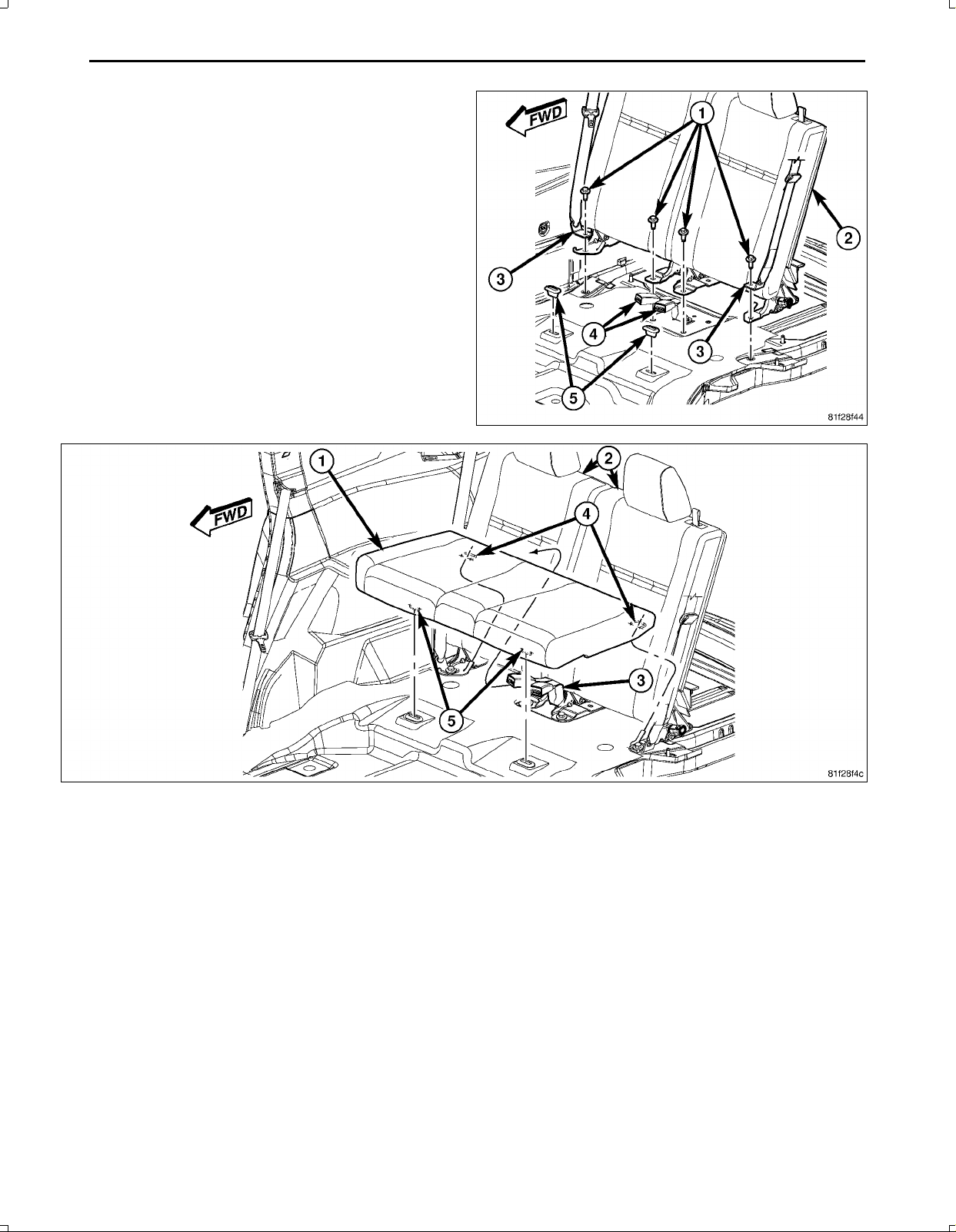
22
www.mopar.com
96.Installtheseatbackfrontmountingfasteners(1).
97.Placethethirdrowseatcushion(1)intoposition.Makesurethattheseatbeltsarepositioncorrectly.
98.Presstheseatcushionback(2)andundertheseatback.
99.Ensuretheseatretaininghooks(4)slideunderthebodysidehooks.
100.Firmlydepressthefrontoftheseatcushiondown,ensuringthattheseatretainers(5)engage.
Feb02,2011K6861161
NOTE:Storagebinwiththirdrowseatshown,withoutthirdrowseatsimilar.
www.mopar.com
101.Placethestoragebox(1)inthevehicleandinstallthefourstorageboxmountingfasteners(4)..
102.Ifequipped,installthestorageboxliner(2).
103.Ifequipped,installthematorloadfloorassemblycoveringthestoragebox.
104.Ifequippedwithathirdrowseat,positiontheseatbackgaphiderandinstalltheretainersontheseatbackgap
hidertotherearstoragebox.
105.Positiontheliftgatesillplateintothevehicleandhand
taptosecuretheretainingclips.
23
Feb02,2011K6861161
 Loading...