

Mopar Jeep Commander (XK), Jeep Grand Cherokee (WK) Installation Instructions Manual

2345678901234567890123456789012123456789012345678901234567890
1
2345678901234567890123456789012123456789012345678901234567890
1
2345678901234567890123456789012123456789012345678901234567890
1
2345678901234567890123456789012123456789012345678901234567890
1
2345678901234567890123456789012123456789012345678901234567890
1
2345678901234567890123456789012123456789012345678901234567890
1
2345678901234567890123456789012123456789012345678901234567890
1
2345678901234567890123456789012123456789012345678901234567890
1
2345678901234567890123456789012123456789012345678901234567890
1
2345678901234567890123456789012123456789012345678901234567890
1
2345678901234567890123456789012123456789012345678901234567890
1
2345678901234567890123456789012123456789012345678901234567890
1
INSTALLATION INSTRUCTIONS
Professional Installation is Recommended
Technical Support
For Authorized Dealers - (800) 34-MOPAR
Hours: 9:00 a.m. - 6:00 p.m. EST Monday thru Friday
10:00 a.m. - 2:00 p.m. EST Saturday
1030930
REV . A
8/05
K6859684
Jeep Grand Cherokee (WK)
Jeep Commander (XK)
Security System
Note: Both Factory RKE Keyfobs are required for
option programming & Driver’s Door Priority Unlock
feature must be enabled.
2
This device complies with part 15 of the FCC rules and with RSS-210 of the
industry Canada. Operation is subject to the following two conditions: (1) this
device may not cause harmful interference, and (2) this device must accept
any interference received, including interference that may cause undesired
operation.
This product was manufactured in environmentally friendly manufacturing
facility and may contain certain recycled materials. All materials meet or
exceed original specifications for quality and reliability.
Jeep Grand Cherokee & Commander
Security System
Table of Contents
VEHICLE PREPARATION................................................................................4
MODULE PREPARATION................................................................................4
COMPONENT INSTALLATION...........................................................................5
SYSTEM PROGRAMMING.............................................................................8
OPTION BANK CHART..................................................................................10
SYSTEM TESTING........................................................................................11
REASSEMBLY.............................................................................................11
SYSTEM LAYOUT.........................................................................................12
2345678901234567890123456789012123456789012345678901234567890
1
2345678901234567890123456789012123456789012345678901234567890
1
2345678901234567890123456789012123456789012345678901234567890
1
2345678901234567890123456789012123456789012345678901234567890
1
2345678901234567890123456789012123456789012345678901234567890
1
2345678901234567890123456789012123456789012345678901234567890
1
2345678901234567890123456789012123456789012345678901234567890
1
2345678901234567890123456789012123456789012345678901234567890
1
2345678901234567890123456789012123456789012345678901234567890
1
2345678901234567890123456789012123456789012345678901234567890
1
Note: Both Factory RKE Keyfobs are required for
option programming & Driver’s Door Priority Unlock
feature must be enabled.
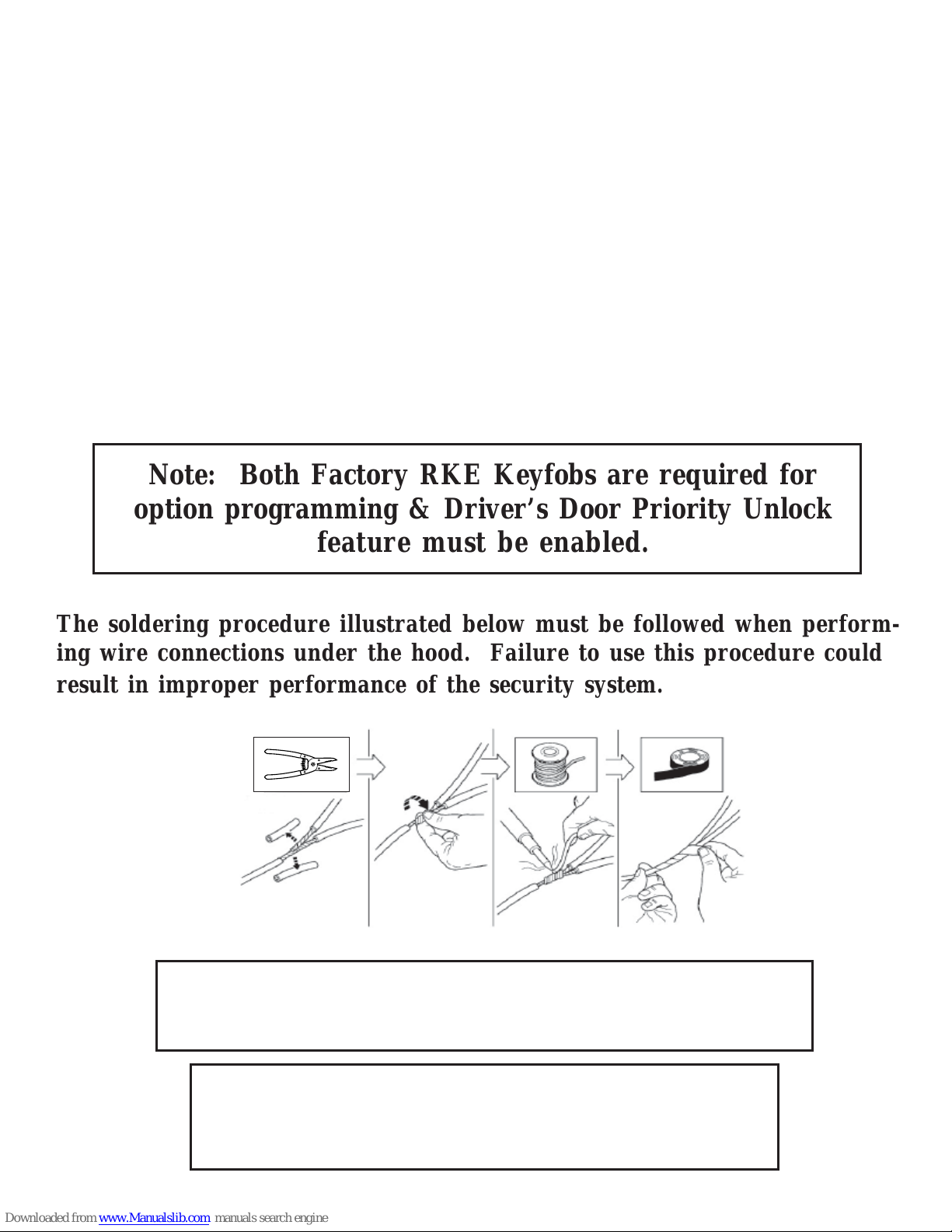
The soldering procedure illustrated below must be followed when performing wire connections under the hood. Failure to use this procedure could
result in improper performance of the security system.
3
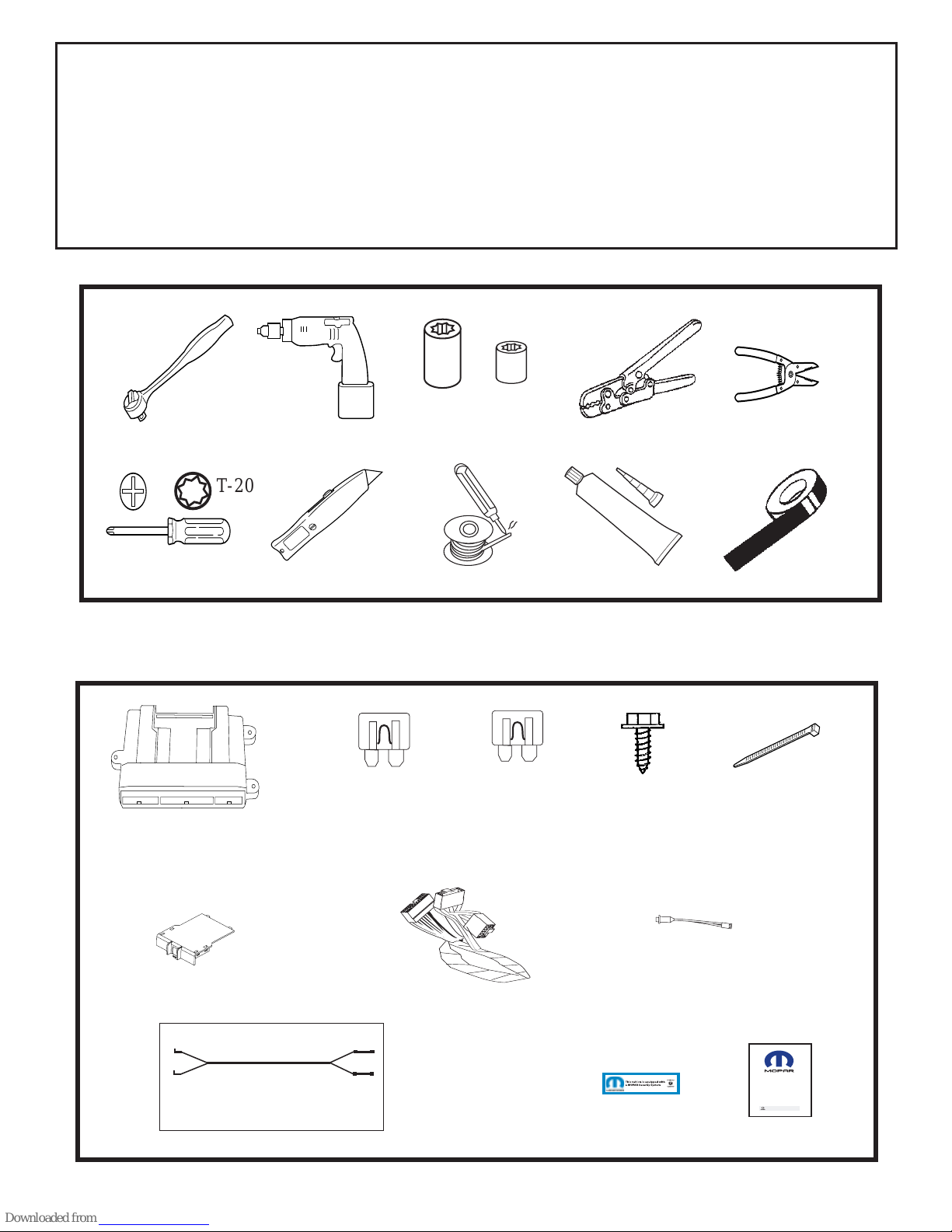
PARTS REQUIRED
Part Number 82209709 (WK) or 82209710 (XK)
5A 1X 15A 1X 1X 5X
Owner's Manual
Vehicle Remote Start System
TM
Featuring PowerCode Technology
For the Ultimate in Comfort, Convenience and Security
TM
®
TOOLS REQUIRED
10mm 1/4”
RTV SEALENT
VEHICLE PREP ARA TION
1. Lower one or more of the passenger windows so the keys do not get locked
in the vehicle.
2. Disconnect and isolate the negative battery cable. The battery will need to be
re-connected before programming.
3. System installation requires 2 working factory RKE keyfobs for pro-
gramming options.
TM
T-
20
WK/XK HORN & PARK LIGHT JUMPER
234
5
234
5
T-20

4
Vehicle Preparation
Remove driver’s side lower dash
panels, located directly under the
steering column and left kick panel.
A. Pull down lower dash & remove.
B. Remove (2) screws from black
under dash panel & remove.
C. Remove left kick panel and sill
plate by gently pulling them off.
Overview
The security module harness will interface with the existing ignition switch connector, horn, parking lights, power doorlock & door trigger connections, and a ground
termination.
Module Preparation
Place fuses into the control module.
A. Observe fuse amperage ratings.
Place the 5 Amp fuse into the “Main
B+” location. Place the 15 Amp fuse
into the negative “PK LIGHTS”
location.
Install DNA into the control module
B. Insert DNA into the control module.
Ensure the DNA assembly snaps
completely in place and no circuit
board pins get bent while closing.
DNA
 Loading...