

Mopar Jeep Commander 82211019xx, 82211019xx Jeep Commander (XK) 2008, 82211019 Installation Instructions Manual
Dealer Installed Factory Remote
Jeep Commander (XK)
82211019xx
INSTALLATION INSTRUCTIONS
ATTENTION!
Start Components
WCM & WIN-BASED VEHICLES DIFFER IN THEIR IN-
STALLATION PROCEDURE. YOU MUST REFER TO PAGE
2 FOR IMPORTANT NOTES. IN ADDITION, PLEASE READ
& UNDERSTAND THE ENTIRE INSTALLATION MANUAL
BEFORE PROCEEDING.
Table of Contents
• Hood Switch Wiring Harness Installation
• Feature Turn On (XBM)
Technical Support - StarSCAN Programming, Installation of:
WIN, Keys, Antenna and Hood Switch Only
For Authorized Dealers - (800) 850-STAR
Canada - (800) 361-2702
Technical Support - Wire Harness Only
For Authorized Dealers - (800) 34-MOPAR
Hours: 9:00 a.m. - 6:00 p.m. EST Monday thru Friday
10:00 a.m. - 2:00 p.m. EST Saturday
** StarSCAN cable CH9404D must be used for this application **
1032625
REV. B
5/08
K6860289AB

WARNING!
XBM remote start can ONLY be installed on
vehicles that have the following factory options:
Automatic Transmission
Remote Keyless Entry
Immobilizer
The installation procedures differ between SKIM(WCM) and WinFobik
based vehicles. With the WinFobik based vehicle, the sales code must be
added to the database and the
StarSCAN tool) must be performed prior to installing the new WIN module. Failure to do so will render the WIN module’s remote start function
inoperative.
The technician should wait 1/2 hour between adding XBM sales code in
DealerConnect before installing the WIN module & restoring vehicle
configuration. In the interim, the technician can install all other components except the WIN module.
Download the following Service Manual documents from Dealer Connect
Restore Vehicle Configuration (using the
before proceeding with installation.
1. WIN module replacement procedure.
2 of 11
VEHICLE PREPARATION
x
1. Lower one or more of the passenger windows so the keys do not get locked in the vehicle.
2. Disconnect and isolate the negative battery cable. The battery will need to be re-connected before
programming.
3. Disassemble and remove keys from old transmitters, install into provided new
transmitters.
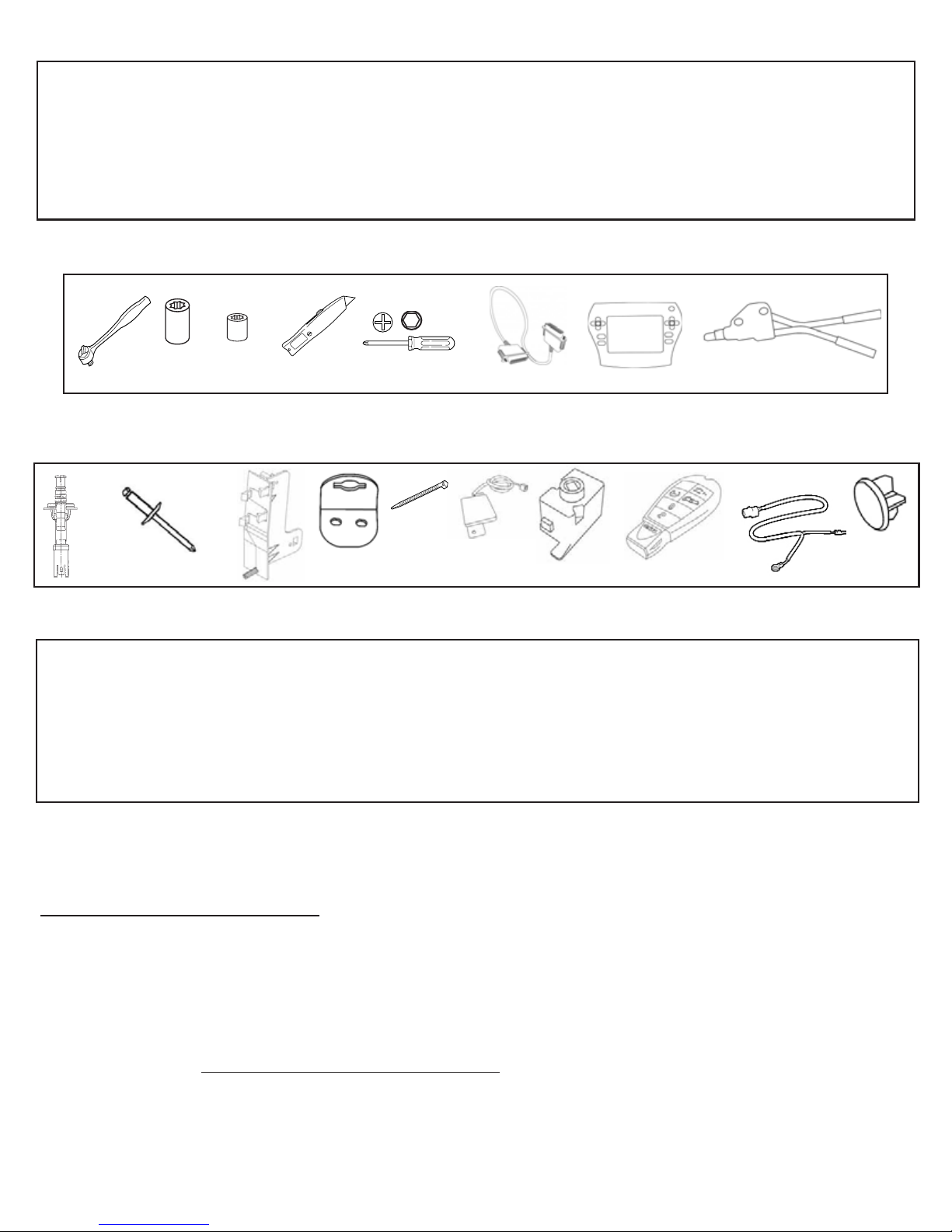
TOOLS REQUIRED
5mm He
10mm 1/4”
StarSCAN Cable CH9404D
KIT CONTENTS
1X
2X
1X
1X
12X
1X
1X
2X
1X
1X
OVERVIEW
This instructional manual will discuss the installation of the hood switch harness & XBM (Remote
Start) turn-on. Other steps will include replacement procedure of the WIN, antenna installation, hood
switch installation, and uploading of vehicle configuration from Dealer Connect. Refer to the vehicle
Service Manual for specific installation procedures for all components except the hood switch harness, which is covered here in detail.
Update Vehicle Configuration
1.Vehicle Vin must be updated with the sales code of the added accessory in order to enable system
functionality. Using the DealerCONNECT website and a StarSCAN diagnostic tool, complete the
following procedure:
a. Log on to https://dealerconnect.chrysler.com
3 of 11
b. In the “Vehicle Option” screen under the “Global Claims System” category in the “Service” tab,
enter vehicle VIN and add sales code(s) noted below as a “Dealer Installed Option”.
XBM (REMOTE START)
c. Confirm that the new sales code has been sucessfully added to the VIN.
d. With the StarSCAN diagnostic tool connected to both the internet (via Ethernet port or wireless connection) and the vehicle, perform the following steps from the Initial Start Up Screen:
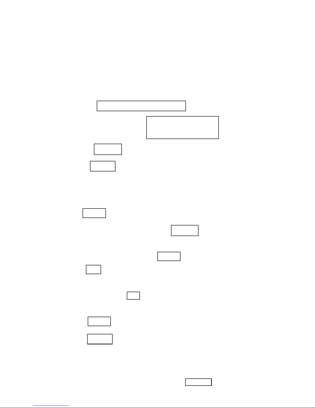
1. Press --------- VEHICLE PREPARATION
2. Toggle Down and Highlight --- RESTORE VEHICLE
CONFIGURATION
3. Press -------- START
4. Press ------- NEXT
5. If necessary, select proper vehicle line and model year and
press ----- NEXT
6. Confirm correct selection and press ----- NEXT
7. Enter vehicle VIN using On-Screen keyboard or confirm that
auto-filled VIN plate and press ----- NEXT
8. Press ----- OK
9. Enter user ID, password and dealer code using On-Screen
keyboard and press ----- OK
10. Wait for vehicle configuration data to be downloaded and
press ----- NEXT
11. Press ----- NEXT
12. Confirm that vehicle configuration has been programmed
sucessfully
13. Note On-Screen instructions and press ----- FINISH
4 of 11
Validation Process
1. Press ----- ECU VIEW
2. Toggle down and highlight ----- TIPM/FCMCGW CENTRAL
GATEWAY
3. Press ----- MORE OPTIONS
4. Press ----- ECU DETAILS
5. Press ----- CONFIG INFO
6. Toggle down, verify:
Name Value
REMOTE START PRESENT SET
Installation Procedure:
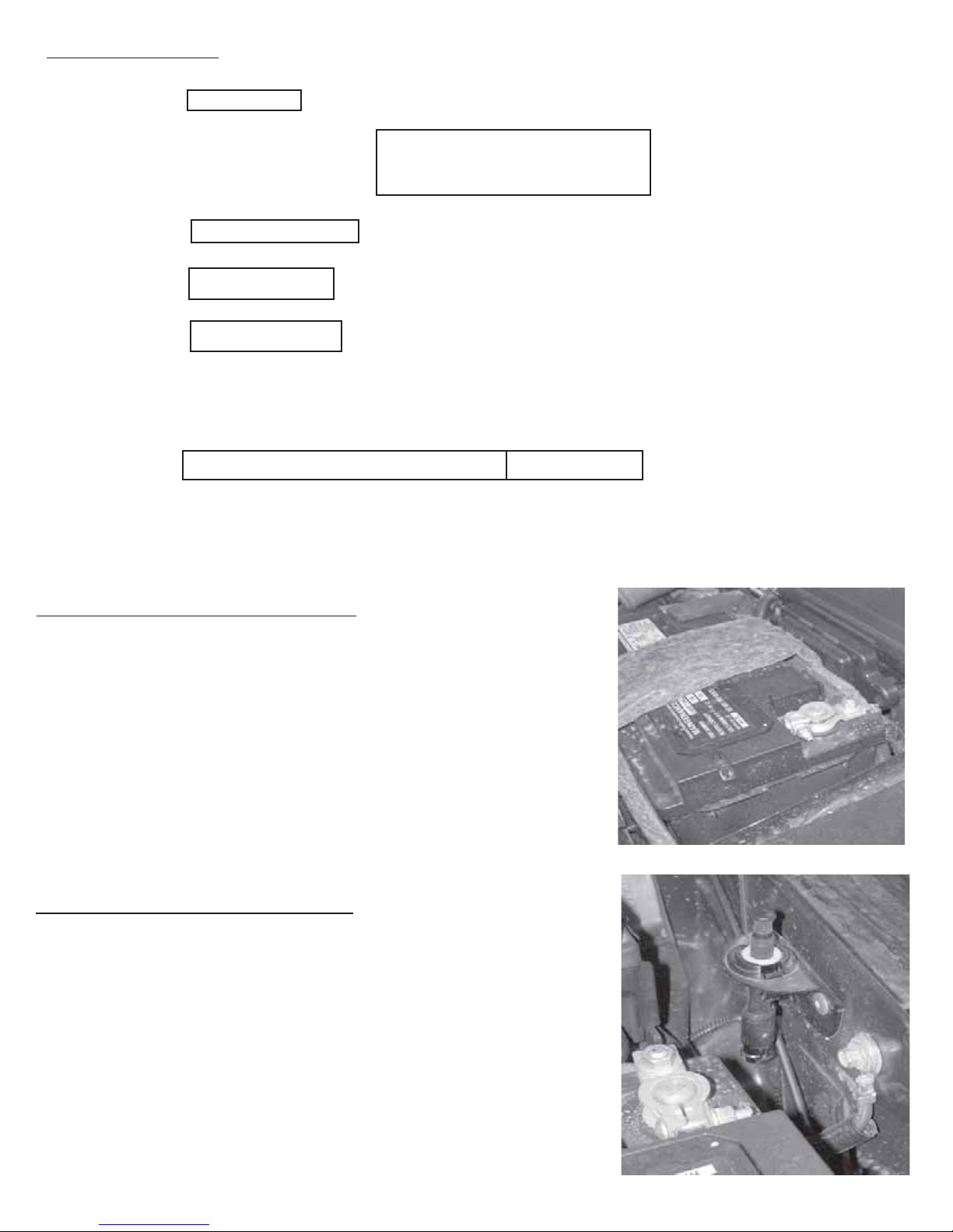
Disconnect Ground From Battery
1. Remove ground from battery
a. Using a 10 mm socket, remove the negative battery cable.
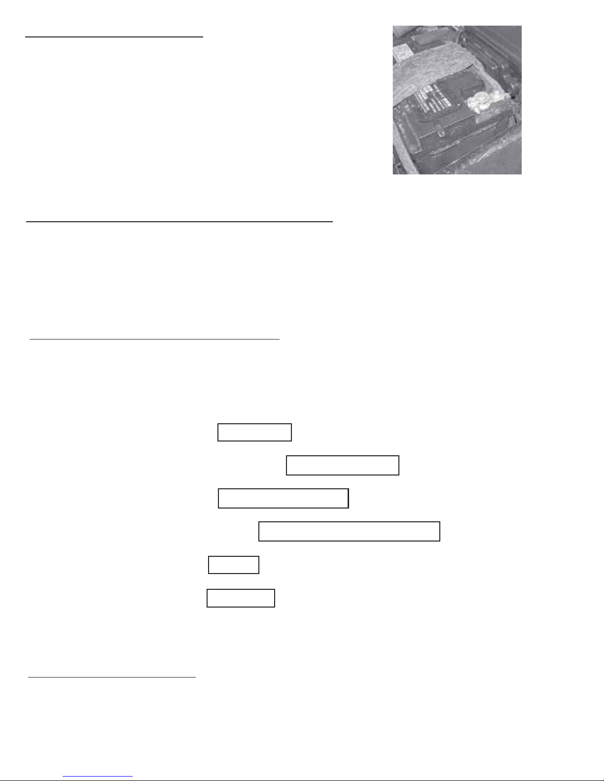
Hood Switch Bracket Installation
1. Mount the hood switch bracket
a. Locate the hood switch mounting location, near the battery on
the driver’s side fender.
b. Using the provided rivits, secure the hood switch bracket to
the driver’s fender.
Note: Loosening or removal of the battery may be necessary.
5 of 11
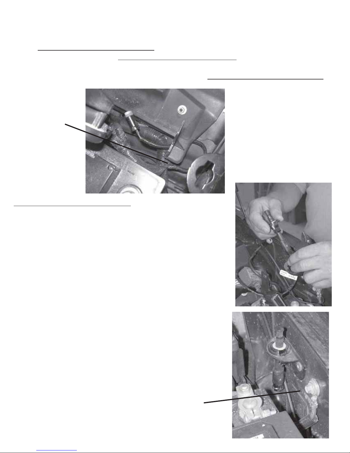
This vehicle may be equipped with a “Factory Installed” hood switch harness. This harness will be secured to the factory harness located near the hood switch mounting location
at the front of the passenger side fender. If this harness is present, Refer to step “a” in
the “Hood Switch Harness Installation” section below and connect the hood pin switch as
described, then proceed to “
Remote Start Antenna Installation” and continue with this
instruction manual. If this vehicle DOES NOT have a factory installed hood switch harness (one is supplied in the kit), complete the entire “Hood Switch Harness Installation”
procedure.
Factory Harness
Location
Hood Switch Harness Installation
1. Routing of the hood switch harness.
a. Route the hood switch harness up through the mount-
ing bracket, located on the driver’s side fender.
b. Connect the hood switch to the harness and insert into
the mounting bracket until properly seated.
c. Using a 10mm socket, remove the factory grounding
lug located on the driver’s side fender, near the battery.
d. Install the hood switch harness ground terminal over
the bolt and reinstall back into the fender.
Ground Location
6 of 11
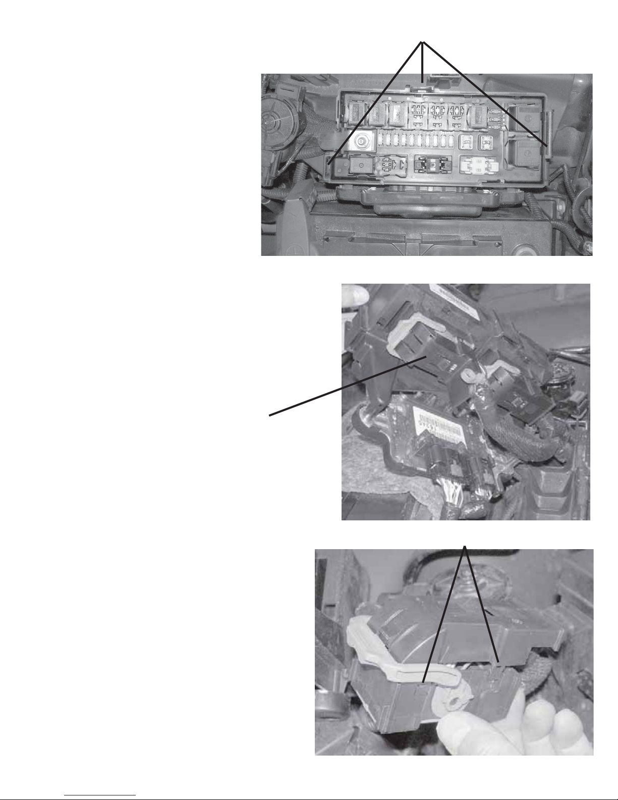
2. Access the connectors underneath the IPM
a. Remove the IPM from the
IPM mounting bracket by
disengaging the (3) retaining clips.
3. Connect the hood switch wire
a. Remove the “II” connector from the IPM.
Retaining Clips
“II” connector
b. Access the terminals on the backside of the
connector by disengaging the retaining clips
(two on each side).
Retaining Clips
7 of 11
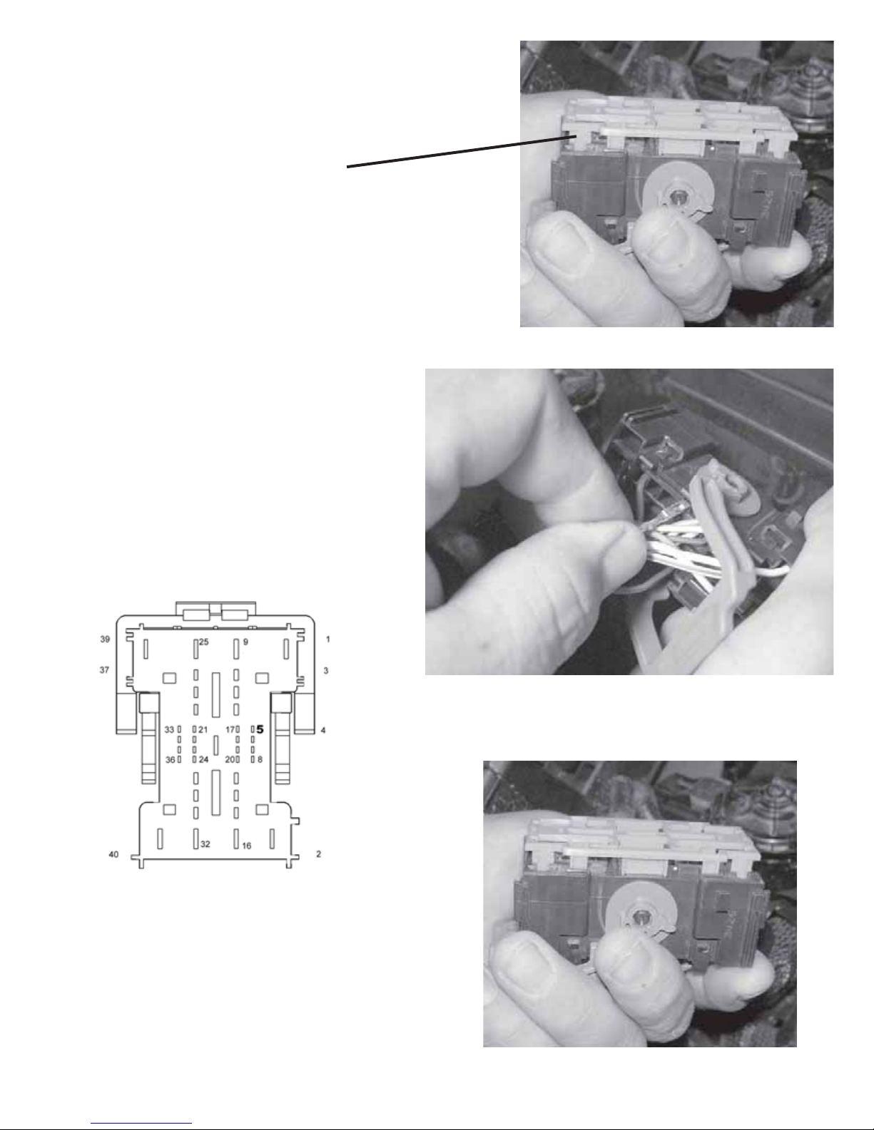
c. Remove the “Secondary Lock” from the
front of the connector.
Secondary Lock
d. Insert the Violet/Lt. Blue wire from the
hood switch harness into the
“II” connector, location 5
(G70 Circuit).
Note: Refer to picture for proper
terminal orientation.
Wire Side View
e. Reinstall the “Secondary Lock” into the front of the
connector.
8 of 11
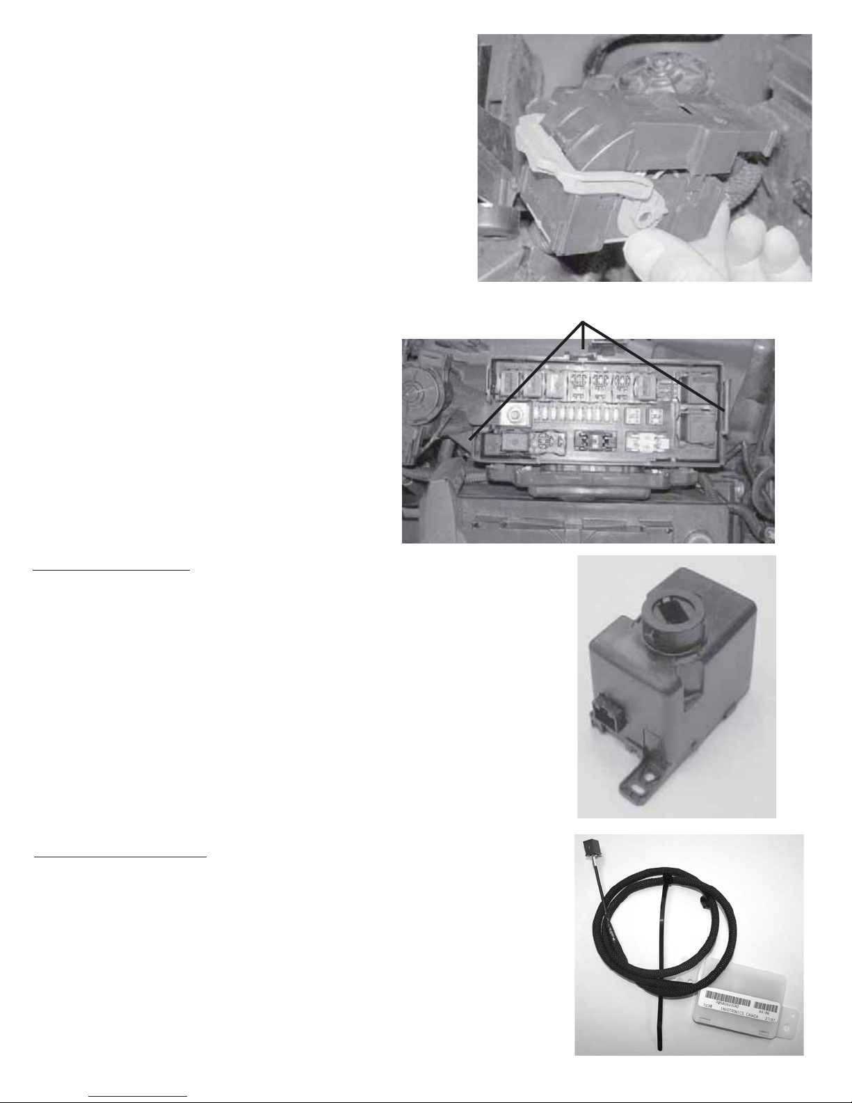
f. Reinstall the protective cover on the back side of
the “II” connector by engaging the (4) retaining
clips.
g. Reinstall the “II” connector back into the IPM.
4. Reinstall the IPM
a. Reinstall the IPM on the
IPM mounting bracket by
engaging the (3) retaining clips.
WIN Replacement
** Orginal WIN must be removed and the new WIN must be
installed **
1. Refer to the vehicle Service Manual section 8 Electrical/
Starting/Remote Start Antenna Module/Installation - for
WIN replacement.
Retaining Clips
Antenna Installation
1. Refer to the vehicle Service Manual section 8 Electrical/Starting/
Remote Start Antenna Module/Installation - for antenna installation.
9 of 11
Reconnect Ground to Battery
1. Reconnect ground to battery
a. Using a 10 mm socket reattach the negative battery cable.
WIN Replacement Procedure using StarSCAN tool
1. Refer to vehicle Service Manual section 8 Electrical/Vehical Theft Security/Standard Procedure/
SKIS INITIALIZATION.
Remote Start Disable Override Procedure
1. With the StarSCAN diagnostic tool connected to both the internet
(via Ethernet port or wireless connection) and the vehicle, perform
the following steps from the Initial Start Up Screen:
a. Press ------------------- ECU VIEW
b. Toggle Down and Highlight --- TIPM/FCMCGW
c. Press ------------------ MISC FUNCTIONS
d. Toggle Down and Highlight REMOTE START OVERRIDE
e. Press ----------------- NEXT
f. Press ----------------- DISABLE
Program All Keys to Vehicle
1. Refer to the vehicle Service Manual for FOBIK key programming procedure.
10 of 11
 Loading...