

Mopar 82210888xx, 82210891xx, 82210888M, 82210891 Installation Instructions Manual

Dealer Installed Factory
Remote Start Components
INST ALLA TION INSTRUCTIONS
82210888xx
82210891xx
2008 Chrysler Aspen (HG)
• Hood Switch Wiring Harness Installation
• Feature Turn On (XBM)
Technical Support - StarSCAN Programming, Installation
of: WCM, Keys, Antenna and Hood Switch Only
For Authorized Dealers - (800) 850-STAR
1032697
REV . A
10/07
Table of Contents
Technical Support - Wire Harness Only
For Authorized Dealers - (800) 34-MOPAR
Hours: 9:00 a.m. - 6:00 p.m. EST Monday thru Friday
10:00 a.m. - 2:00 p.m. EST Saturday
K6860221
20
VEHICLE PREP ARATION
1. Lower one or more of the passenger windows so the keys do not get locked in the
vehicle.
2. Disconnect and isolate the negative battery cable. The battery will need to be
re-connected before programming.
3. Locate and cut provided new keys prior to remote start installation.
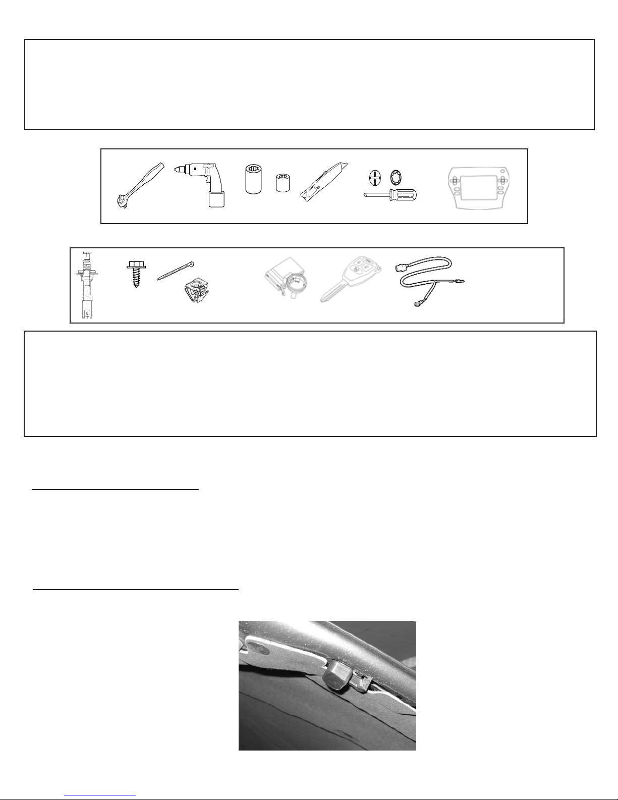
TOOLS REQUIRED
T-
10mm 1/4”
KIT CONTENTS
1X
2X
12X
2X
1X
1X
2X
1X
1X
OVERVIEW
This instructional manual will discuss the installation of the hood switch harness & XBM
(Remote Start) turn-on. Other steps will include replacement procedure of the WCM,
antenna installation, hood switch installation, and uploading of vehicle configuration from
Dealer Connect. Refer to the vehicle Service Manual for specific installation procedures
for all components except the hood switch harness, which is covered here in detail.
Installation Procedure:
Hood Switch Installation
1. Refer to the vehicle Service Manual section 8 Electrical/
Vehicle Theft Security/Hood Ajar Switch/Installation - for
Hood Switch installation.
Hood Striker Plate Installation
1. Attach Striker to vehicle hood as shown.
2 of 11

Disconnect Ground From Battery
1. Remove ground from battery
a. Using a 10mm socket remove the negative battery cable.
Hood Switch Harness Installation
1. Access the bottom of the TIPM
a. Access the connectors at the bottom of the
TIPM by releasing the (3) locking tabs in the
corners of the TIPM and lift upwards.
2. Routing and connection of the hood
switch harness
a. Route the hood switch harness connector
through the opening in the fender, next to the
factory harness.
Hood Switch Harness
Locking T abs
Factory Harness
3 of 11

Access Panel
b. Using the access panel in the wheel well lining,
route the hood switch connector up through the
opening pictured in the next step.
c. Attach the hood switch to the connector and push into
the opening until properly seated.
4 of 11

d. Route the ground wire underneath the TIPM mounting bracket
to the factory ground lug located at the rear of the driver’s side
fender.
e. Using a 10 mm socket, remove the factory ground lug.
Factory Ground
TIPM Mounting
Bracket
f. Insert the hood pin switch ground ring terminal over the
10 mm bolt and reinstall into the fender .
g. Route the remaining V iolet/White wire from the hood
switch harness underneath the TIPM mounting bracket and
upwards towards the “I” connector.
Violet/Lt. Blue Wire
TIPM Mounting
Bracket
5 of 11

h. Remove the “I” connector from the TIPM.
IPM
i. Disengage the (4) locking tabs on the side of
the connector, to gain access to the wires underneath.
“I” Connector
Locking Tabs
(2 on each side)
j. Remove the “Secondary Lock” on the front of
the connector.
Secondary Lock
6 of 11
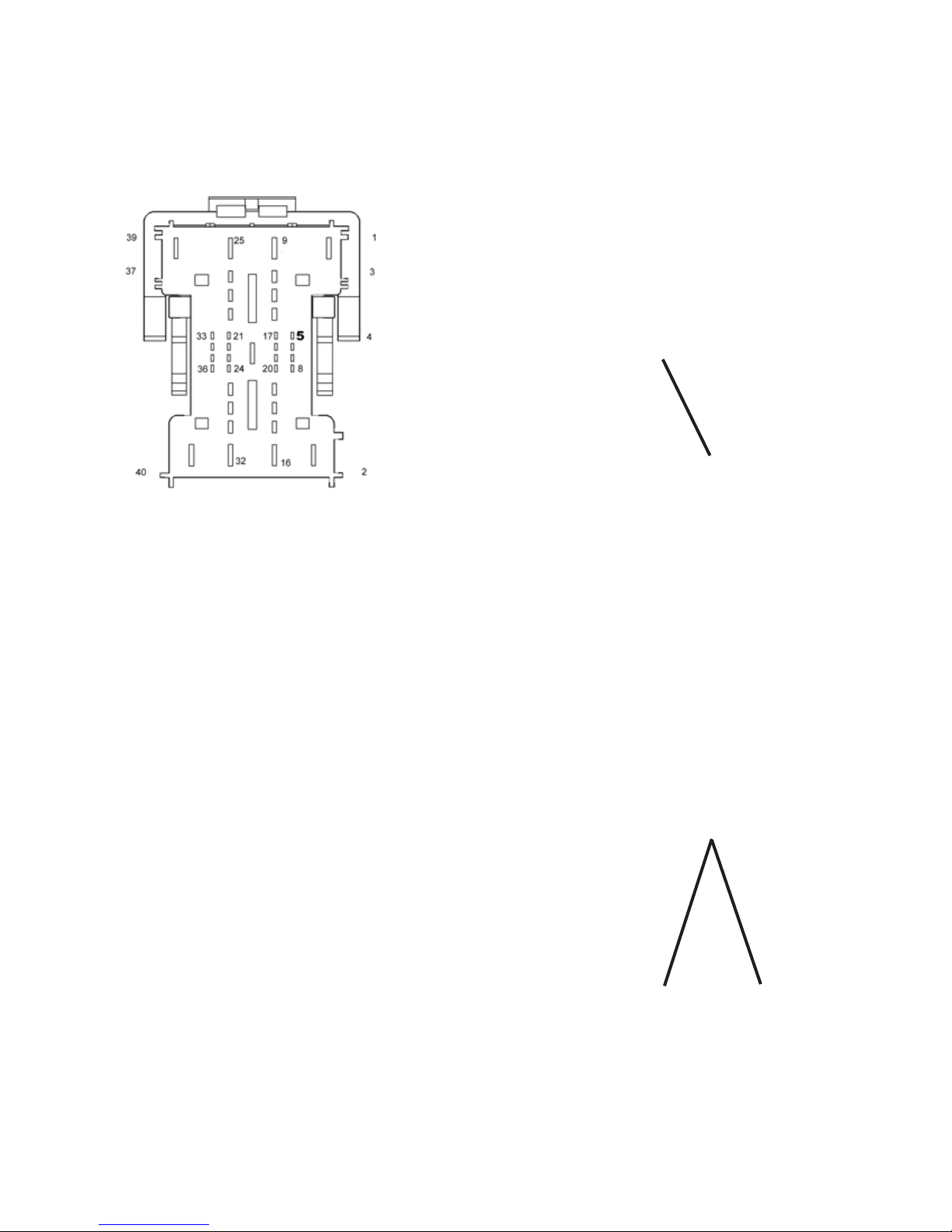
k. Insert the Violet/White wire from the hood switch
harness into cavity # 5 (G70 circuit).
Note: Reference picture for proper
terminal orientation.
Secondary Lock
Wire Side View
l. Reinsert the “Secondary Lock” into the face
of the connector.
m. Reinstall the plastic cover of the rear of the
connector, by engaging the (4) locking tabs.
Locking Tabs
(2 on each side)
7 of 11

n. Secure the Violet/White wire to the factory harness using
supplied wire tie.
Wire Tie
o. Resecure the “I” connector into the TIPM.
3. Resecure the TIPM
a. Resecure the TIPM on the TIPM mounting
bracket by re-engaging the (3) locking tabs.
Locking Tabs
WCM Replacement
** Orginal WCM must be removed and the new WCM must be installed **
1. Refer to the vehicle Service Manual section 8 Electrical/
Starting/Remote Start Antenna Module/ Installation - for
WCM replacement.
8 of 11

Antenna Installation
1. Refer to the vehicle Service Manual section 8 Electrical/ Start-
ing/Remote Start Antenna Module/Installation - for antenna installation.
Reconnect Ground to Battery
1. Reconnect ground to battery
a. Using a 10 mm socket reattach the negative battery
cable.
WCM Replacement Procedure using StarSCAN tool
1. Refer to vehicle Service Manual section 8 Electrical/Vehical Theft Security/ Standard
Procedure/SKIS INITIALIZATION.
Update Vehicle Configuration
1.Vehicle Vin must be updated with the sales code of the added accessory in order to enable system
functionality . Using the DealerCONNECT website and a S tarSCAN diagnostic tool, complete the
following procedure:
a. Log on to https://dealerconnect.chrysler.com
9 of 11

b. In the “Vehicle Option” screen under the “Global Claims System” category in the “Service” tab,
enter vehicle VIN and add sales code(s) noted below as a “Dealer Installed Option”.
XBM (REMOTE START)
c. Confirm that the new sales code has been sucessfully added to the VIN.
d. With the StarSCAN diagnostic tool connected to both the internet (via Ethernet port or wireless connection) and the vehicle, perform the following steps from the Initial Start Up Screen:
1. Press --------- VEHICLE PREPARATION
2. Toggle Down and Highlight --- RESTORE VEHICLE
CONFIGURATION
3. Press -------- START
4. Press ------- NEXT
5. If necessary, select proper vehicle line and model year and
press ----- NEXT
6. Confirm correct selection and press ----- NEXT
7. Enter vehicle VIN using On-Screen keyboard or confirm that
auto-filled VIN plate and press ----- NEXT
8. Press ----- OK
9. Enter user ID, password and dealer code using On-Screen
keyboard and press ----- OK
10. Wait for vehicle configuration data to be downloaded and
press ----- NEXT
11. Press ----- NEXT
12. Confirm that vehicle configuration has been programmed
sucessfully
13. Note On-Screen instructions and press ----- FINISH
10 of 11
 Loading...