

Mopar 82209992, 82209991 Installation Instructions Manual

2345678901234567890123456789012123456789012345678901234567890
1
2345678901234567890123456789012123456789012345678901234567890
1
2345678901234567890123456789012123456789012345678901234567890
1
2345678901234567890123456789012123456789012345678901234567890
1
2345678901234567890123456789012123456789012345678901234567890
1
2345678901234567890123456789012123456789012345678901234567890
1
2345678901234567890123456789012123456789012345678901234567890
1
2345678901234567890123456789012123456789012345678901234567890
1
2345678901234567890123456789012123456789012345678901234567890
1
2345678901234567890123456789012123456789012345678901234567890
1
2345678901234567890123456789012123456789012345678901234567890
1
2345678901234567890123456789012123456789012345678901234567890
1
INST ALLATION INSTRUCTIONS
Professional Installation is Recommended
Technical Support
For Authorized Dealers - (800) 34-MOPAR
Hours: 9:00 a.m. - 6:00 p.m. EST Monday thru Friday
10:00 a.m. - 2:00 p.m. EST Saturday
1031263
REV . A
5/06
K6859657
2007 Jeep Wrangler (JK)
Security System
Note: For EVS I installations, both Factory RKE Keyfobs are
required for option programming & Driver’s Door Priority
Unlock feature must be enabled.
2
This device complies with part 15 of the FCC rules and with RSS-210 of the
industry Canada. Operation is subject to the following two conditions: (1) this
device may not cause harmful interference, and (2) this device must accept
any interference received, including interference that may cause undesired
operation.
This product was manufactured in environmentally friendly manufacturing
facility and may contain certain recycled materials. All materials meet or
exceed original specifications for quality and reliability.
Jeep Wrangler (JK)
Security System
T able of Contents
Vehicle Preparation...................................................................................4
Module Preparation...................................................................................5
Custom Harness Installation.....................................................................6
System Programming.............................................................................10
EVS I Programming................................................................................10
EVS II Programming...............................................................................12
Option Bank Chart...................................................................................13
System Testing.........................................................................................14
Reassembly..............................................................................................14
System Layout..........................................................................................15
2345678901234567890123456789012123456789012345678901234567890
1
2345678901234567890123456789012123456789012345678901234567890
1
2345678901234567890123456789012123456789012345678901234567890
1
2345678901234567890123456789012123456789012345678901234567890
1
2345678901234567890123456789012123456789012345678901234567890
1
2345678901234567890123456789012123456789012345678901234567890
1
2345678901234567890123456789012123456789012345678901234567890
1
2345678901234567890123456789012123456789012345678901234567890
1
2345678901234567890123456789012123456789012345678901234567890
1
2345678901234567890123456789012123456789012345678901234567890
1
2345678901234567890123456789012123456789012345678901234567890
1
2345678901234567890123456789012123456789012345678901234567890
1
Note: For EVS I installations, both Factory RKE
Keyfobs are required for option programming &
Driver’s Door Priority Unlock feature must be enabled.
3
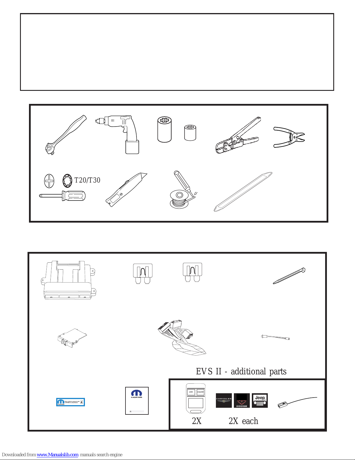
PARTS REQUIRED
Part Number 82209992 (EVS I) or 82209991 (EVS II)
5A 1X 15A 1X 1X 5X
Owner's Manual
Vehicle Remote Start System
TM
Featuring PowerCode Technology
For the Ultimate in Comfort, Convenience and Security
TM
®
TOOLS REQUIRED
10mm 1/4”
VEHICLE PREP ARATION
1. Lower one or more of the passenger windows so the keys do not get locked
in the vehicle.
2. Disconnect and isolate the negative battery cable. The battery will need to be
re-connected before programming.
3. EVS I System installation requires 2 working factory RKE keyfobs for
programming options.
TM
T-
20
234567890123456789012345678901212
3
234567890123456789012345678901212
3
234567890123456789012345678901212
3
234567890123456789012345678901212
3
234567890123456789012345678901212
3
234567890123456789012345678901212
3
234567890123456789012345678901212
3
234567890123456789012345678901212
3
234567890123456789012345678901212
3
234567890123456789012345678901212
3
EVS II - additional parts
ARM DISARM
2X 2X each
23
4
23
4
T20/T30

4
Vehicle Preparation
Remove driver’s side lower dash panels,
& steering column shroud.
A. Pull down on lower dash. Panel is
held by clips. Start at the top corners.
Remove panel.
B. Remove (3) bolts holding metal panel
in place. Pull up on the panel to
remove.
C. Remove lower plastic dash panel.
Panel is held by clips.
D. Remove (3) screws from steering
column shroud. Separate and remove
steering column shroud.
E. Remove driver’s side kick panel/sill
plate. Panel is held on by clips.
Overview
The security module harness will interface with the existing ignition switch connector, horn, parking lights, power doorlock & door trigger connections, and a ground
termination.
5
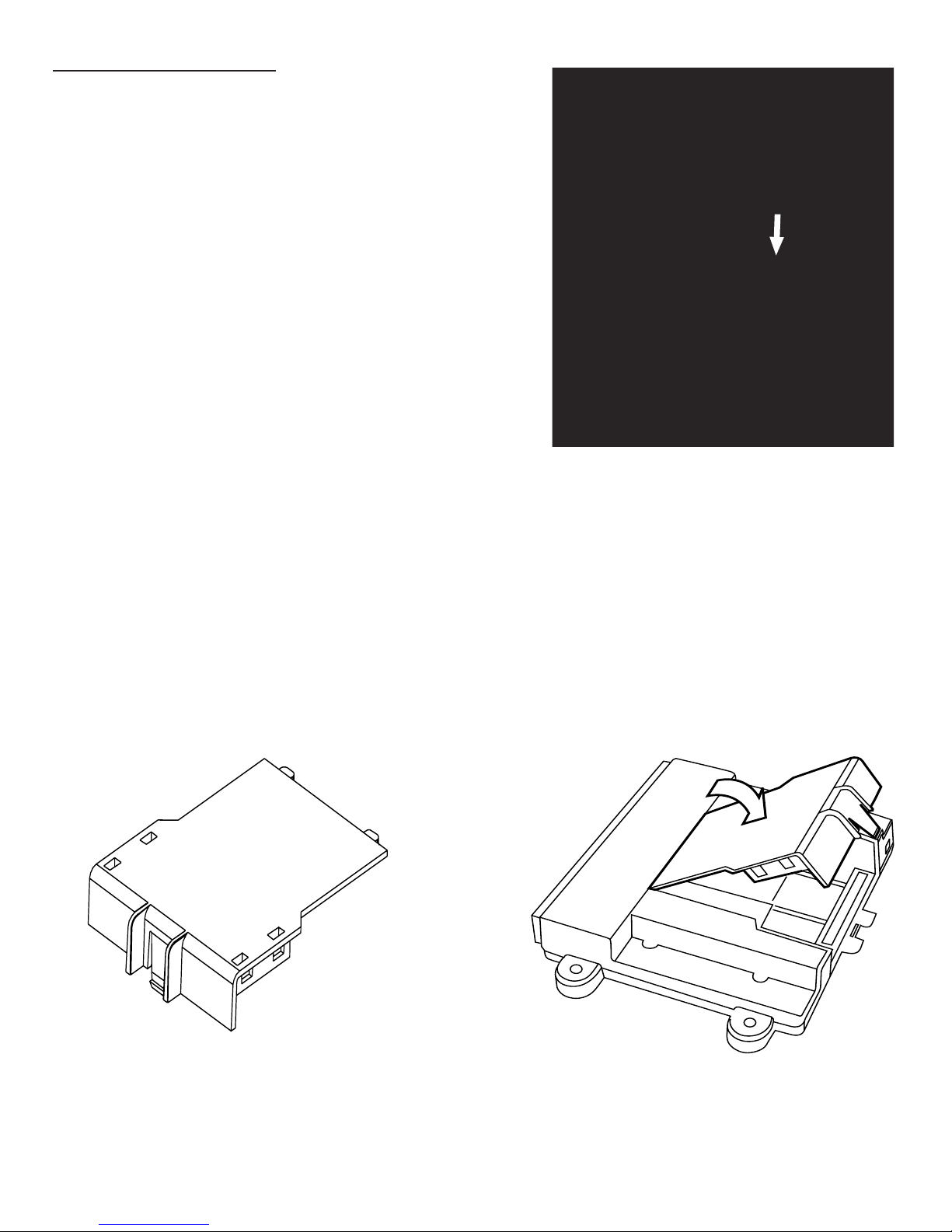
Module Preparation
Place fuses into the control module.
A. Observe fuse amperage ratings. Place
the 5 Amp fuse into the “Main B+”
location. Place the 15 Amp fuse into
the positive “PK LIGHTS” location.
Install DNA into the control module.
B. Insert DNA into the control module.
Ensure the DNA assembly snaps
completely in place and no circuit
board pins get bent while closing.
DNA

6
Custom Harness Installation
Ignition switch connector
A. Locate ignition switch connector,
directly behind the ignition switch.
Release the secondary lock. While
pushing on main release, remove
connector from ignition switch.
B. Connect the harness 5-way female
connector to the vehicle’s ignition
switch.
C. Connect the harness 5-way male
connector to the vehicle’s 5-way
ignition connector previously
removed from the ignition switch.
Ground
D. Using a supplied 1/4” screw,
secure the black ground wire with
ring terminal to the driver’s side left
kick panel metal.
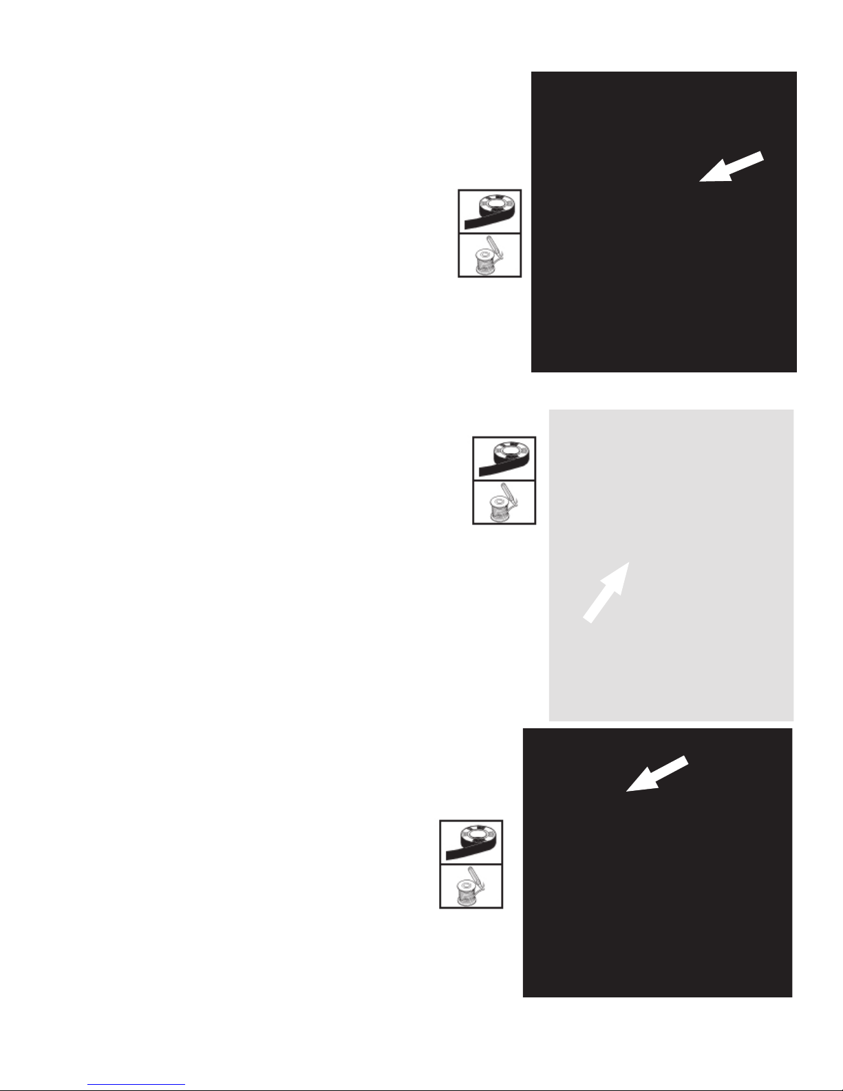
Parking Light Connection
E. Locate the White/V iolet (L217) wire in
harness, found low in the left kick
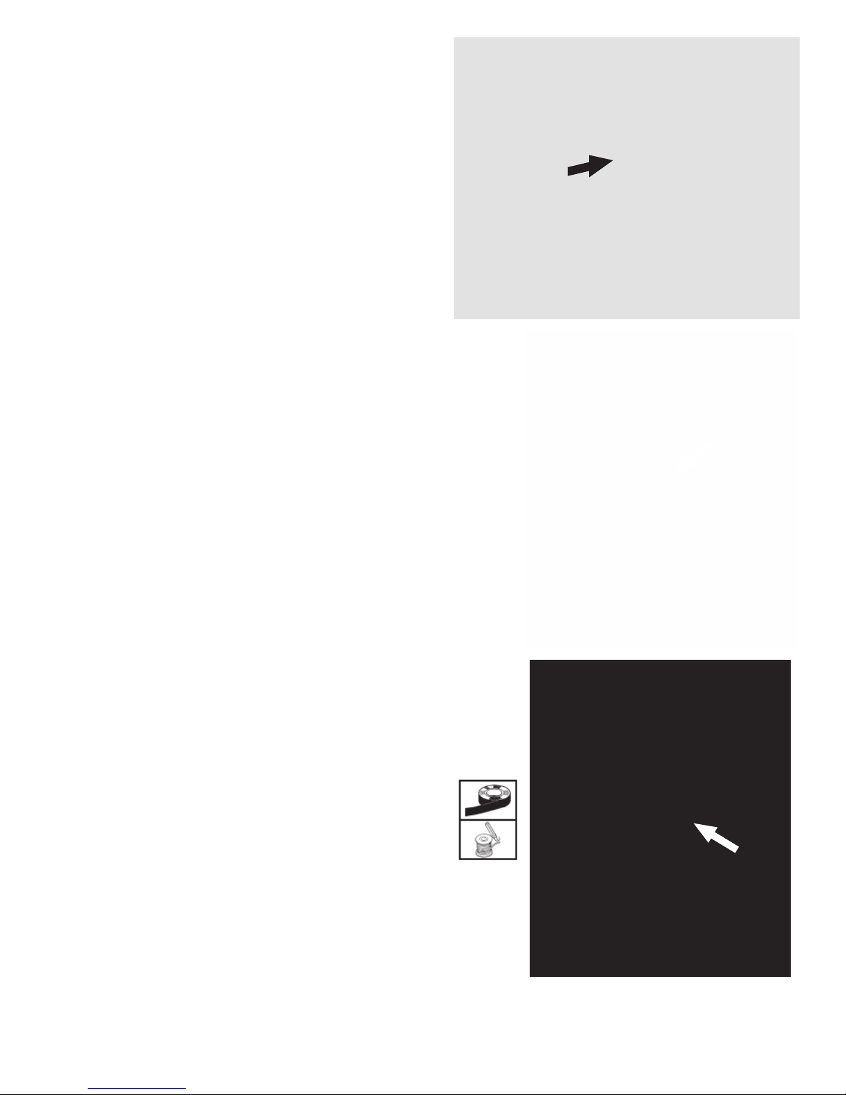
panel area. Center-splice the
harness Yellow wire into this wire,
following the center-splice procedure as shown. This wire will show
+12V when the parking lights are
turned on.
Center-Splice Procedure
7
Arm Wire Connection (EVS I only!)
F. Locate the Lt Green/Grey wire in the driver kick
panel. This wire will show +12 volts when the doors
are locked using the keyfob. Center-splice
the harness Lt Blue wire into this wire, following the center-splice procedure.
Disarm Wire Connection (EVS I only!)
G. Locate the T an/Brown wire in the driver kick
panel. This will will show +12 volts when the doors
are unlocked on the first press of the unlock button on the keyfob. Center-splice the harness Brown
wire into this wire, following the center-splice procedure.
Unlock Sense Wire Connection (EVS I only!)
H. Locate the Tan/Brown wire in in the passenger kick
panel. This wire will show +12 volts when the doors
are unlocked only on the second press of the unlock
button on the keyfob. Center-splice the harness Lt
Green wire into this wire, following the center-splice
procedure.
Door T rigger Connection
I. Locate the Yellow/White dome light
feed wire (M24), found at the
underdash courtesy light. Centersplice to the White wire on the
main security harness.
Power Door Lock Connections - Used for EVS I only .
Skip to S tep I for EVS II.
8
LED
J. Drill 9/32” hole in trim panel as
shown in diagram. Exact placement needs to be determined
before drilling. Ensure there is
nothing on the backside of the
panel and there is enough depth for
the LED.
K. Route the remaining Dk Green wire
through the cowl panel and into the
engine compartment through an existing
grommet.
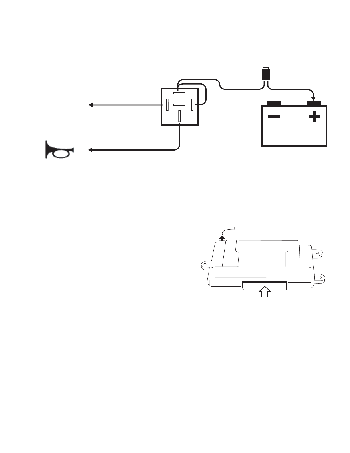
Horn Connections
L. Locate the Grey/Y ellow (X21) wire in the
green “C” connector (pin #18) found
underneath the TIPM module. Centersplice the relay harness Grey wire (pin
30) into this wire, following the centersplice procedure. Solder the connection.
This wire will show +12V when the horn
is activated.
M. Connect the relay harness Red wire (pin
87) to the positive battery post.
N. Route the remaining relay harness Dk
Green wire (pin 85) to the Dk Green (-)
HORN output wire on the main security
harness. Solder the connection.
9
Security Module Connections
O. Connect the 24-way connector into
the PC-12 Security module. Also,
connect the antenna connector (EVS II
Systems only) on end opposite the
main harness connector.
24-Way
Antenna
87
8685
30
87a
(+)
20A Fuse
Connect to (-)HORN output (pin #21)
from security module
Dk Green wire
Dk Green
Grey
Red
Connect to Grey/Yellow (X21) at
TIPM Green “C” Connector (pin #18)
 Loading...