

Mopar 82209870AG Installation Instructions Manual

INST ALLA TION INSTRUCTIONS
Professional Installation Is Recommended
Technical Support
For Authorized Dealers - (800) 34-MOPAR
Hours: 9:00 a.m. - 6:00 p.m. EST Monday thru Friday
10:00 a.m. - 2:00 p.m. EST Saturday
1030882
REV . A
8/05
2006 Chrysler PT Cruiser
K6859619
Remote Start System
Warning! Remote Start Systems are only appli-
cable to vehicles with automatic transmission!
2
This device complies with part 15 of the FCC rules and with RSS-210 of the
industry Canada. Operation is subject to the following two conditions: (1) this
device may not cause harmful interference, and (2) this device must accept
any interference received, including interference that may cause undesired
operation.
This product was manufactured in environmentally friendly manufacturing
facility and may contain certain recycled materials. All materials meet or
exceed original specifications for quality and reliability.
2006 Chrysler PT Cruiser Remote Start
Table of Contents
Vehicle Preparation..................................................................................4
Module Preparation..................................................................................6
Component Installation.............................................................................7
System Programming.............................................................................12
System Testing.........................................................................................16
Service Mode...........................................................................................16
Reassembly..............................................................................................17
Option Bank Chart...................................................................................18
Troubleshooting.......................................................................................19
Changing Transmitter Batteries.............................................................19
System Layout..........................................................................................20
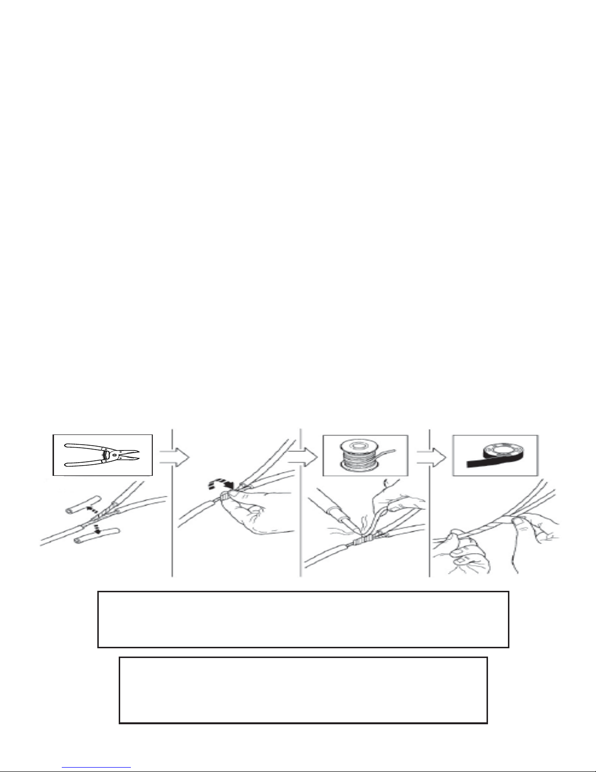
The soldering procedure illustrated below must be followed when performing wire connections under the hood. Failure to use this procedure could
result in improper performance of the remote start system.
3
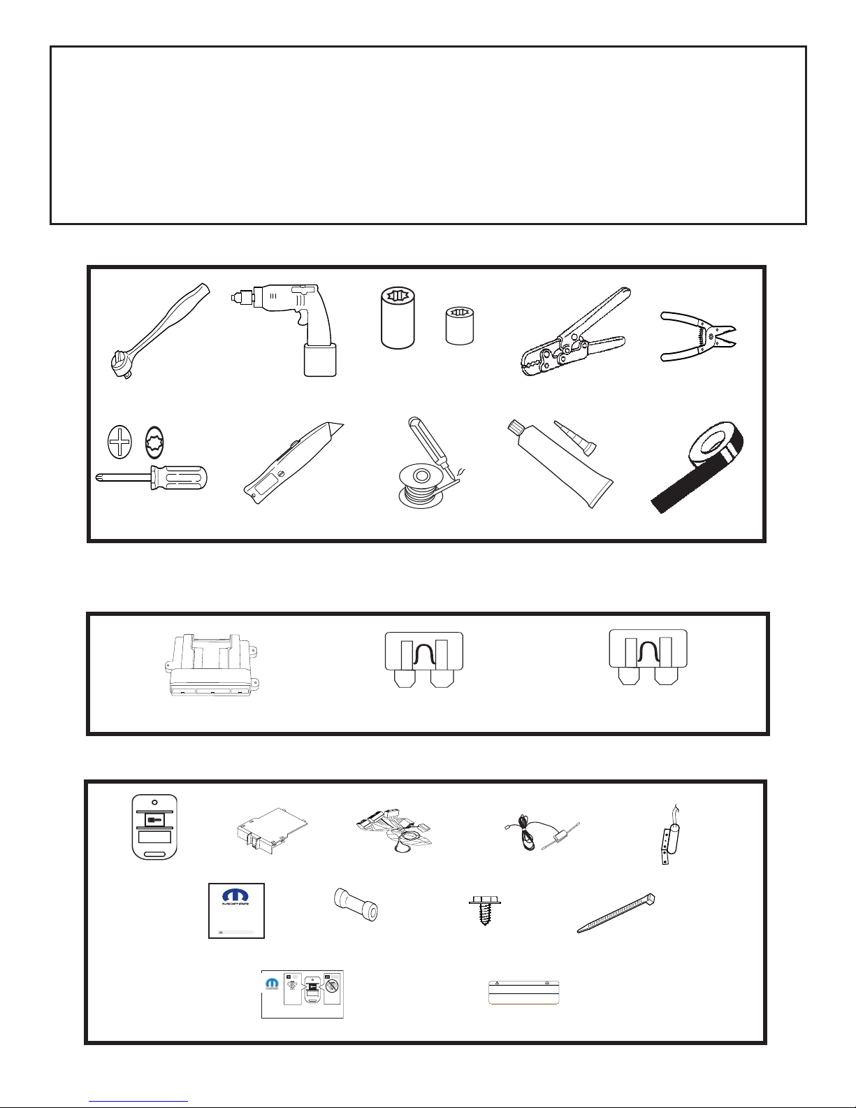
PARTS REQUIRED
Part Number 82208859
5 AMP 1X 15 AMP 4X
WARNING: / AVERTISSEMENT
This vehicle is equipped with a remote controlled engine starter.
To reduce the risk of serious Injury or death, switch engine starter
system into service mode and disconnect the vehicle battery
before performing any service on the vehicle.
Ce véhicule est doté d'un démarreur à distance. Pour réduire les
risques de blessures graves ou mortelles, mettre le démarreur à
distance en mode service et débrancher la batterie du véhicule
avant d'effectuer des travaux d'entretien sur celui-ci.
Owner's Manual
Vehicle Remote Start System
TM
Featuring PowerCode Technology
For the Ultimate in Comfort, Convenience and Security
TM
®
1024256 12/03
Remote Control
Car Starter System
Remote Start
Activation
2X
Remote Start
Shutdown
2 sec.
2X 4X 10X
2X
TOOLS REQUIRED
10mm 1/4”
RTV SEALENT
VEHICLE PREP ARA TION
1. Lower one or more of the passenger windows so the keys do not get locked
in the vehicle.
2. Disconnect and isolate the negative battery cable. The battery will need to be
re-connected before programming.
3. Vehicle requires 2 valid Sentry Keys (if equipped) present at the time of
installation.
2X (French &English)
T-2
0
Part Number 82209870

4
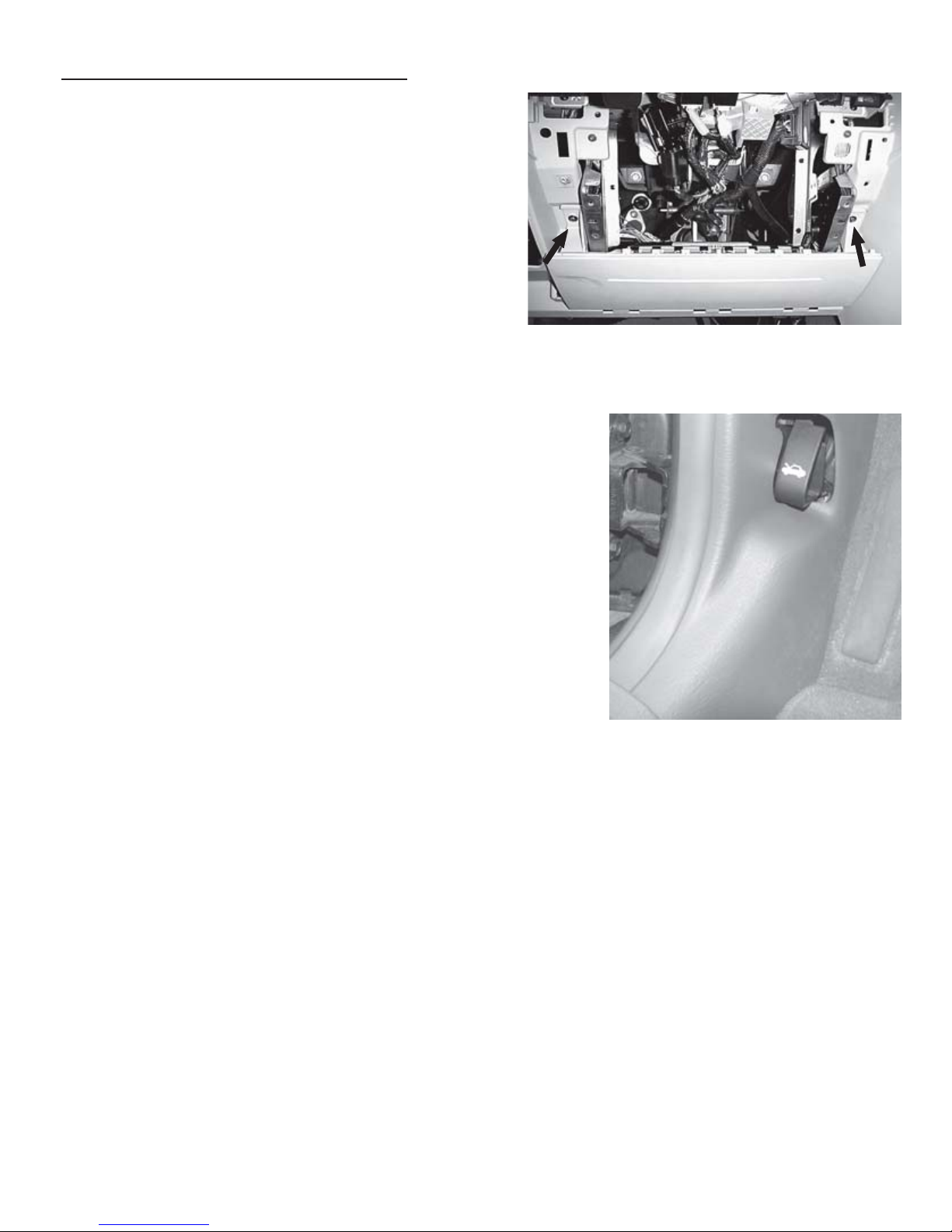
Vehicle Preparation
Remove driver’s side lower dash
panel, metal dash panel, air bag &
steering column shroud.
A. Remove the lower dash panel by
using a trim stick to release the
catch tabs on the backside of the
panel. The top is held on by clips.
Remove dash panel.
B. Remove (4) screws from metal
panel.
C. Remove (3) screws from steering
column shroud. Seperate and
remove steering column shroud.
D. Remove (1) screw from left dash
panel and remove panel. Disconnect connector if necessary.
E. Remove (1) screw from the cluster
cover panel located to the left of
the steering column.
Overview
The remote starter module harness will interface with the existing PT ignition
switch connector, four center-splice connections, and a ground termination. Two
wires will be routed through the cowl panel, to a hood-mounted safety switch and
tachometer connection.
5
F. Remove (2) screws from the top
corner of the air bag cover.
G. Remove (2) screws from air bag
module. Disconnect connector
after ensuring battery is disconnected. Removal of the air bag is
not mandatory, but makes the
installation easier.
Vehicle Preparation Continued
H. Remove left kick panel. Panel is
held on by clips.
6
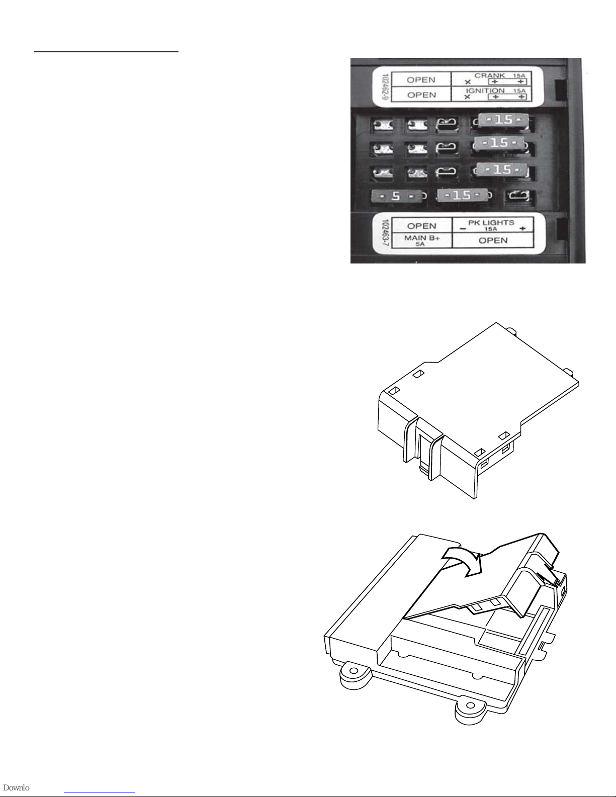
Module Preparation
Place fuses into the control module.
A. Observe fuse amperage ratings. Place
the 5 Amp fuse into the “Main B+”
location. Populate the remaining fuse
locations, as shown in the diagram,
with the 15 Amp fuses. Make sure to
populate the 15 amp fuse with the
“open” fuse label on the module.
Install DNA into the control module.
B. Insert DNA into the control module.
Ensure the DNA assembly snaps
completely in place.
DNA
12
12
12
 Loading...