

Mopar 82208859, 82208994 Installation Instructions Manual

INSTALLATION INSTRUCTIONS
Professional Installation Is Recommended
Technical Support
For Authorized Dealers - (800) 34-MOPAR
Hours: 9:00 a.m. - 6:00 p.m. EST Monday thru Friday
10:00 a.m. - 2:00 p.m. EST Saturday
1030191
REV . B
10/04
K6859230
Système de démarrage à distance
NOTICE D’INSTALLATION
Installation par un spécialiste conseillée
Jeep
Grand Cherokee (WK)
Remote St art System
Warning! Remote Start Systems are only appli-
cable to vehicles with automatic transmission!
2
This device complies with part 15 of the FCC rules and with RSS-210 of the
industry Canada. Operation is subject to the following two conditions: (1) this
device may not cause harmful interference, and (2) this device must accept
any interference received, including interference that may cause undesired
operation.
This product was manufactured in environmentally friendly manufacturing
facility and may contain certain recycled materials. All materials meet or
exceed original specifications for quality and reliability.
Jeep Grand Cherokee (WK)
Remote Start System
Table of Contents
Vehicle Preparation..................................................................................4
Module Preparation..................................................................................5
Component Installation.............................................................................6
System Programming.............................................................................10
System T esting.........................................................................................13
Service Mode...........................................................................................13
Reassembly..............................................................................................14
Option Bank Chart...................................................................................15
Troubleshooting........................................................................................16
Changing Transmitter Batteries.............................................................16
System Layout..........................................................................................17
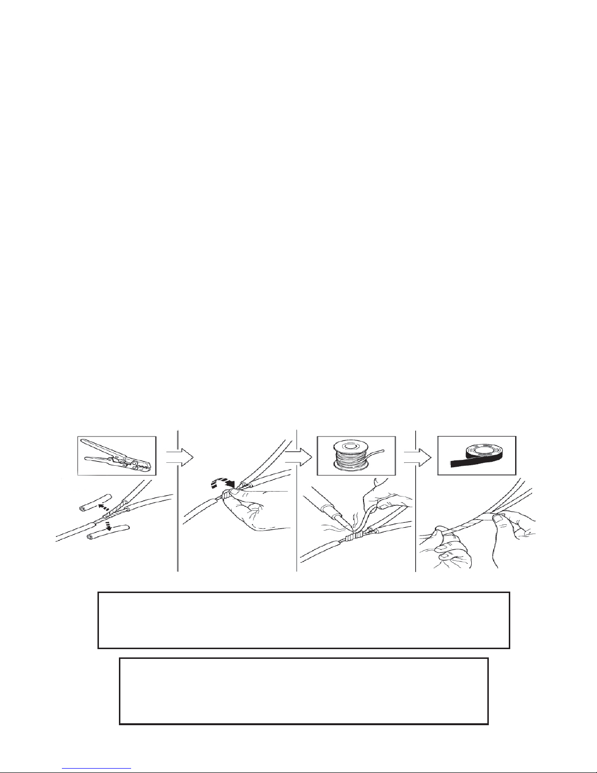
The soldering procedure illustrated below must be followed when performing wire connections under the hood. Failure to use this procedure could
result in improper performance of the remote start system.
3
PARTS REQUIRED
Part Number 82208859
5 AMP 1X 15 AMP 4X
WARNING: / AVERTISSEMENT
This vehicle is equipped with a remote controlled engine starter.
To reduce the risk of serious Injury or death, switch engine starter
system into service mode and disconnect the vehicle battery
before performing any service on the vehicle.
Ce véhicule est doté d'un démarreur à distance. Pour réduire les
risques de blessures graves ou mortelles, mettre le démarreur à
distance en mode service et débrancher la batterie du véhicule
avant d'effectuer des travaux d'entretien sur celui-ci.
Owner's Manual
Vehicle Remote Start System
TM
Featuring PowerCode Technology
For the Ultimate in Comfort, Convenience and Security
TM
®
1024256 12/03
Remote Control
Car Starter System
Remote Start
Activation
2X
Remote Start
Shutdown
2 sec.
2X 4X 10X
2X
Part Number 82208994
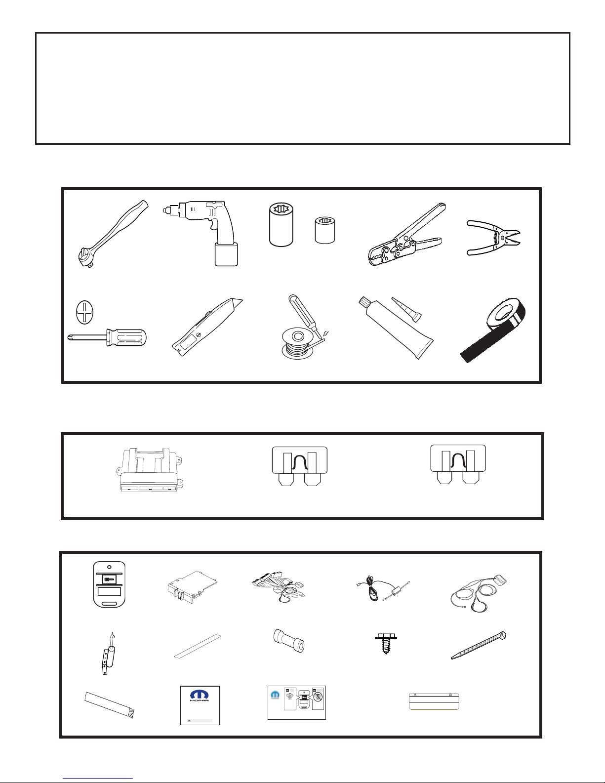
TOOLS REQUIRED
10mm 1/4”
RTV SEALENT
VEHICLE PREP ARA TION
1. Lower one or more of the passenger windows so the keys do not get locked
in the vehicle.
2. Disconnect and isolate the negative battery cable. The battery will need to be
re-connected before programming.
3. V ehicle requires 2 valid Sentry Keys present at the time of installation.
2X (French &English)
4
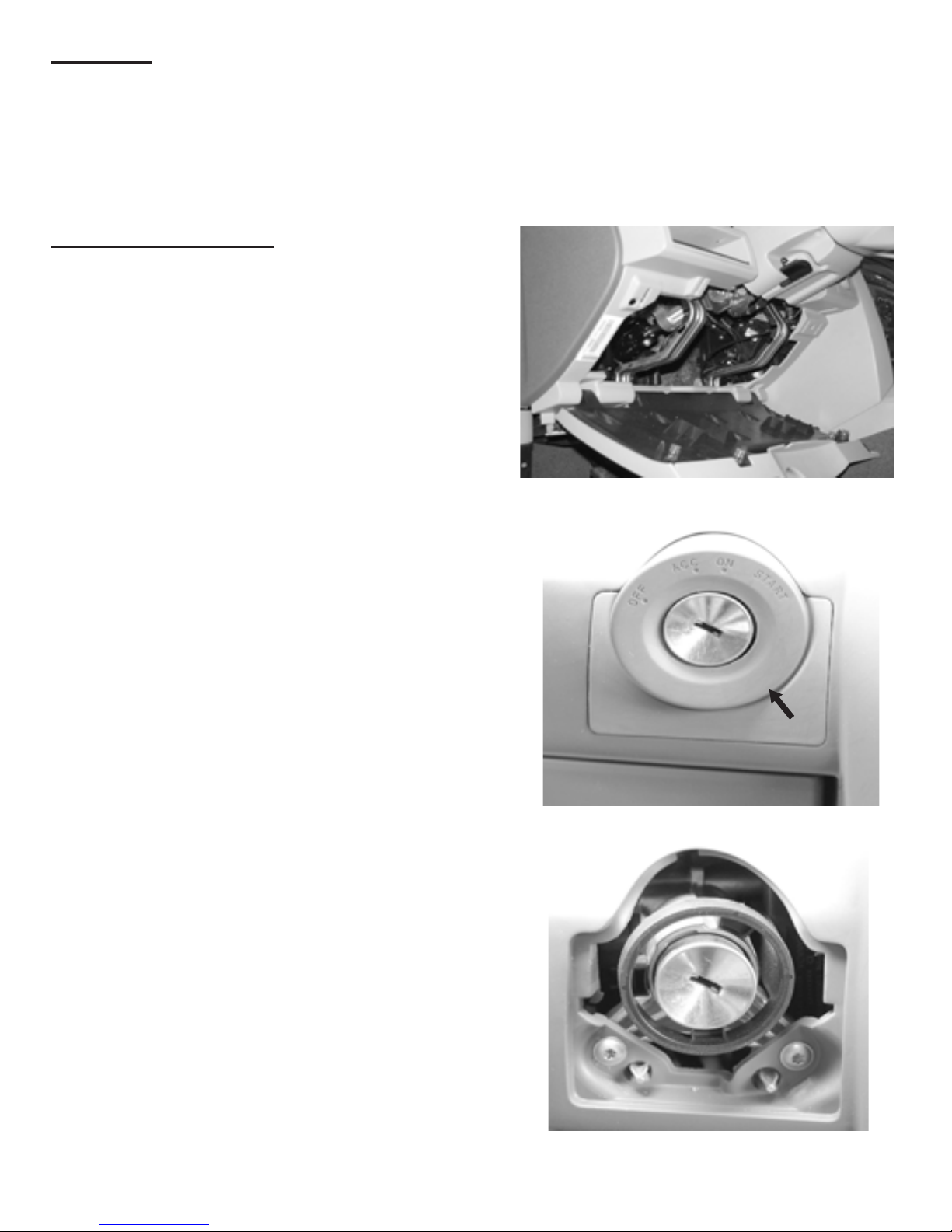
Vehicle Preparation
1. Remove driver’s side lower dash
panels, located directly under the
steering column and ignition switch
bezel.
A. Pull down lower dash & remove.
B. Remove (2) screws from black
under dash panel & remove.
C. Remove ignition cylinder cover .
Carefully pry off using a small
screwdriver or similar tool. Do not
damage the panel.
Overview
The remote starter module harness will interface with the existing WK ignition
switch connector , two center-splice connections, three butt connections, and a
ground termination. Four wires will be routed through the cowl panel, to a hood-
mounted safety switch, horn, parking light, and tachometer connections.
5
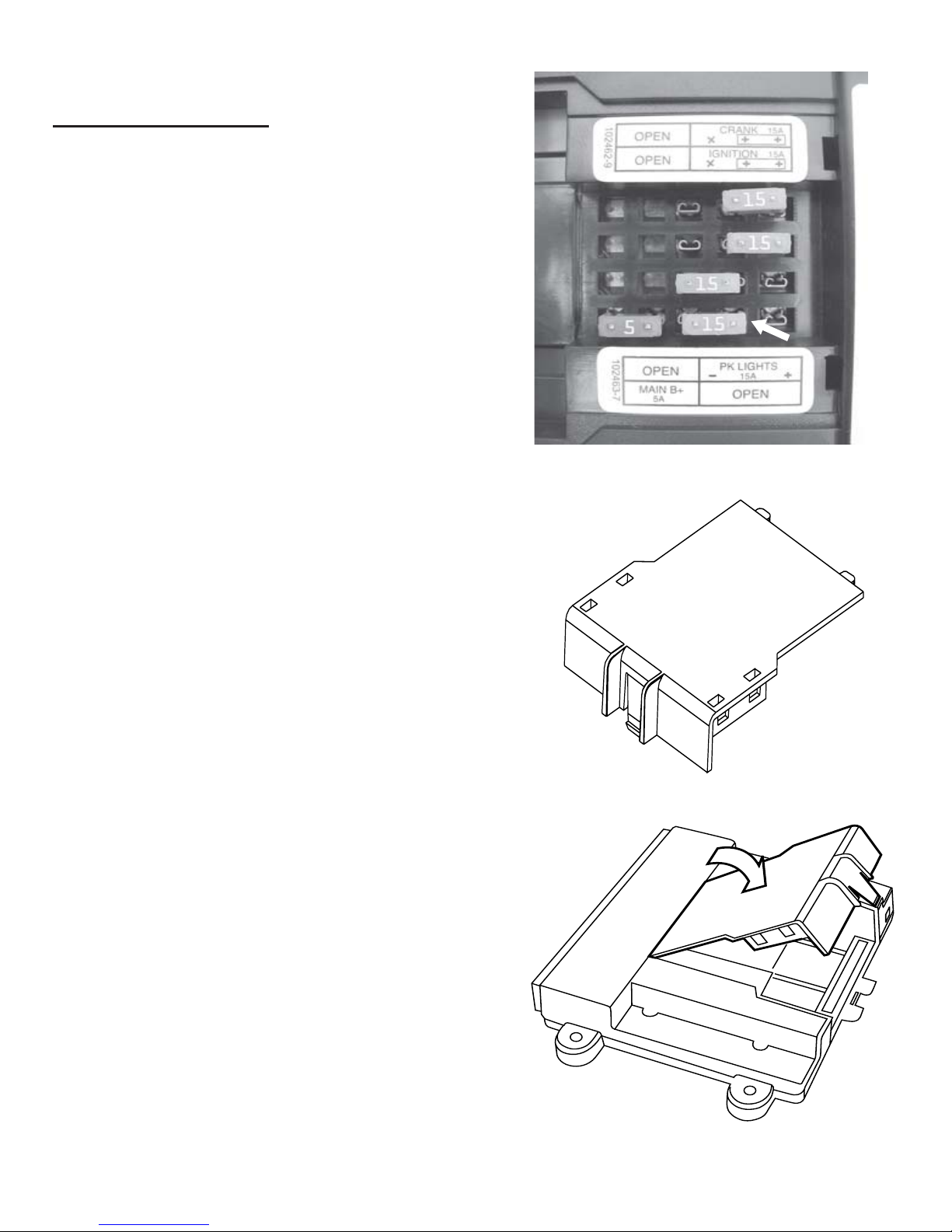
Module Preparation
1. Place fuses into the control module.
A. Observe fuse amperage ratings.
Place the 5 Amp fuse into the
“Main B+” location. Populate the
remaining fuse locations, as
shown in the diagram, with the 15
Amp fuses. Ensure the 15 Amp
fuse is placed in the “OPEN”
location next to “PK LIGHTS”.
2. Install DNA into the control module
A. Insert DNA into the control module.
Ensure the DNA assembly snaps
completely in place.
DNA
6
Component Installation
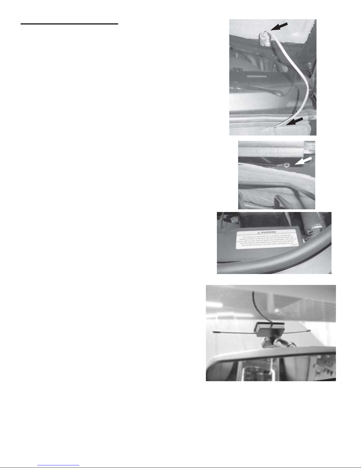
1. Install Hood Safety Switch.
A. Using (2) of the supplied 1/4”
screws, secure hood safety switch
on driver’s side rear corner of hood
per the diagram. Note: Wire exits
top of switch. Switch must be
bent at 45 degree angle.
B. Route the hood safety switch
wiring under the engine compartment cover panel as shown in the
diagram.
C. Using a supplied 1/4” screw ,
secure the ground lead from the
switch to the cowl as shown in the
diagram. The remaining wire will be
connected later .
D. Locate a visible area in the front of
the engine compartment to mount
the underhood warning sticker as
shown in the diagram.
2. Install Dipole Antenna
A. Mount dipole antenna to the
windshield above the rearview mirror
and below the black windshield
trim.
B. Run the antenna wire above the
headliner to the driver’s A-pillar .
T emporarily remove the A-pillar
rubber gasket and run the antenna
lead down through the left side
dash opening. Replace the rubber
gasket. Ensure the antenna is
securely tucked above the headliner and is not visible along the
entire length.
7
B. Connect the harness 5-way female
connector to the vehicle’s ignition
switch.
C. Connect the harness 5-way male
connector to the vehicle’s 5-way
ignition connector previously
removed from the ignition switch.
D. Using a supplied 1/4” screw , secure
the black ground wire with ring
terminal to the metal under dash
brace as shown in diagram.
3. Install Custom Harness.
A. Locate ignition switch connector ,
directly behind the ignition switch.
Release the red secondary lock.
While pushing on main release,
remove connector from ignition
switch.
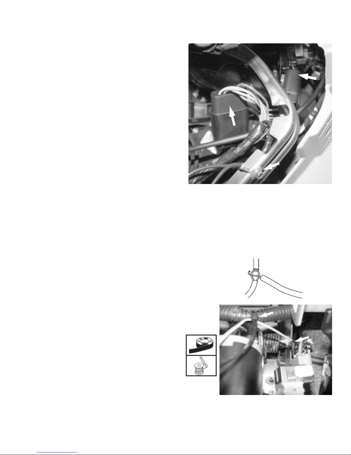
E. Run the harness White/Green wire
to the brake switch. Connect by
center-splice to the White/Green
wire in Cavity #2 of the grey 6-way
brake connector , following the
center-splice procedure above.
Secure wire to the factory wire
harness with a wire tie as shown.
Caution: Keep wire away from
the exposed steering column!
Caution: Do not remove the
brake lamp switch from the
mounting bracket. If the switch
is removed from the mounting
bracket, it MUST be replaced
with a new switch.
Center-S plice Procedure
8
G. Using the supplied butt connector,
connect the Black/White wire to
the remaining wire from the hood
safety switch.
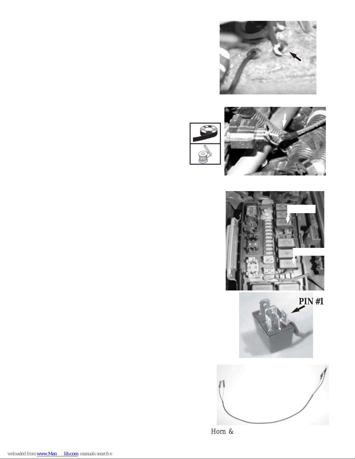
H. Route the Dk Blue/Y ellow wire to
the top of the engine at the coil
connection point as shown. Center-splice the Dk Blue/Y ellow wire
to the Dk Blue/Yellow wire at the
coil, following the center-splice
procedure on page 7. Solder the
connection
I. Route the Green and Yellow wires to
the relay junction box on the driver
side of the engine compartment.
Remove the horn relay as shown in
the diagram. Slide the supplied Green
wire relay terminal connector over
terminal 85 (pin #1) of the relay as
shown in the diagram.
Remove the parking light relay as
shown in the diagram. Slide the
Y ellow wire relay terminal connector
over terminal 85 (pin #1)of the parking
light relay as shown in the diagram.
Re-insert the relays into place.
Route the wiring from the relay
connectors out of the junction box
and connect the Green wire of the
jumper to the Green wire of the
harness using the supplied butt
connector . Connect the Y ellow wire
of the jumper to the Yellow wire of the
harness using the supplied butt
connector .
F. Route the four remaining wires
(Black/White, Green, Yellow, and
Dk Blue/Y ellow) through the cowl
panel and into the engine compartment.
PIN #1
Horn & Parking Light Jumper (included)
23456
7
HORN
234567
8
PK L TS
9
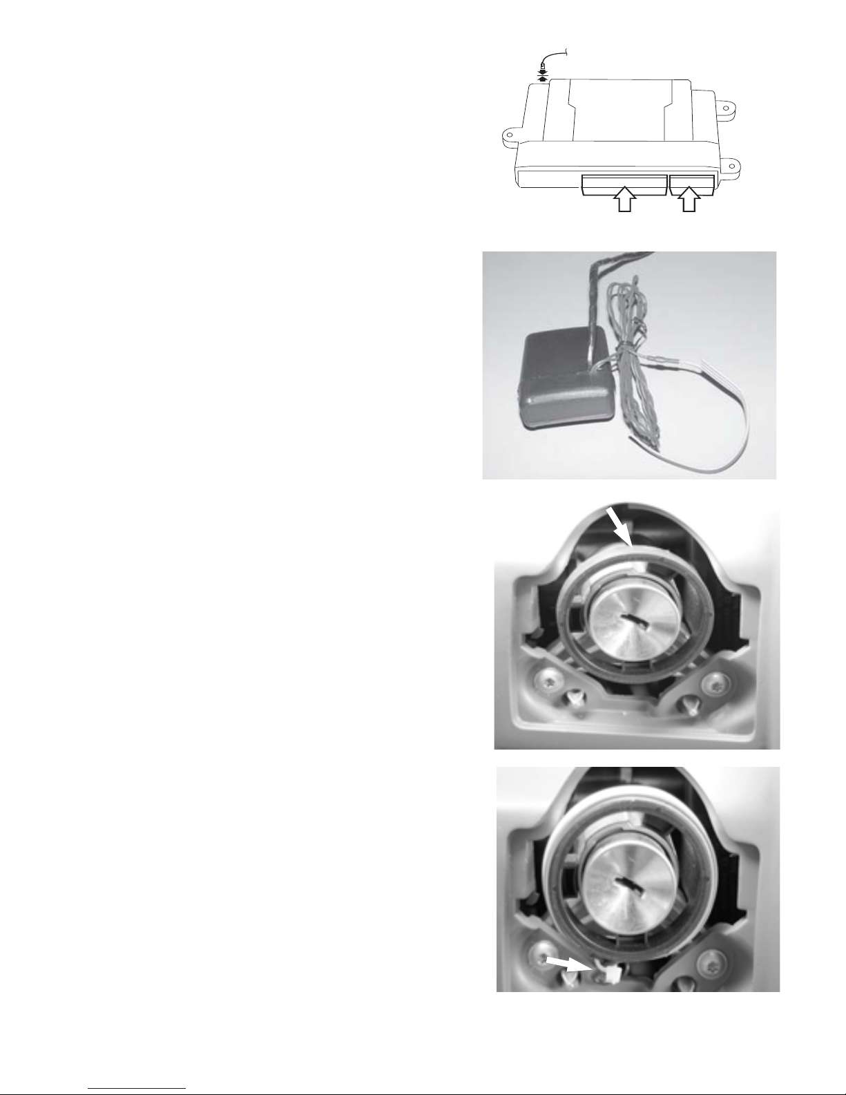
4. Install SKREEM Interface Module.
A. Following the directions on the
supplied ampule of adhesive
primer , apply a thin coating of
primer to the entire SKREEM
transceiver antenna coil. Allow the
primer to dry for 5 minutes before
proceeding to the next step. Note:
Use goggles and gloves to
protect yourself from any accidental contact.
B. Remove backing from one side of
the supplied two-way tape and
apply tape around the transceiver
antenna coil.
C. Route the antenna loop from the
SKREEM Interface module to the
ignition cylinder .
D. Remove the remaining backing on
the tape and position the antenna
loop on the tape around the
transeiver antenna coil. Ensure the
red stripe faces out towards the
key . Press down on antenna coil
to ensure a strong bond.
E. Using a supplied tie wrap, secure
the antenna coil as shown.
K. Connect the 24-way and 10-way
connectors into the PC-12 Remote
S t art module. Also, connect the 2way antenna connector (on end
opposite the main harness connections).
24-Way
10-Way
Antenna

10
1. Transmitter Programming.
A. Make sure battery is connected.
B. Close hood.
C. T urn the ignition to the “on” position.
D. Press and hold the programming button. After 10 seconds the horn will
chirp and the lights will flash 3 times indicating the system is now in
transmitter learn mode.
E. Release the programming button.
F. Press button on transmitter to be programmed. The horn will chirp and the
lights will flash 1 time indicating that the transmitter has been learned.
G. Repeat step F for additional transmitters.
2. Option Programming.
The remote start system has several installer programmable options which
can be changed to accomodate different circumstances. In most cases, there
will be no need to change any default settings. There will be cases (such as
deisel vehicles), where the delay before crank option must be set.
Note:
This system has 2 option banks. Bank 1 has 7 options, and Bank 2 has 2
options. Refer to the Options Bank Chart on page 15 for details.
A. Follow the steps above to enter T ransmitter Learn Mode.
B. Press and release the programming button. The horn will chirp and the
lights will flash 4 times indicating the system has entered Option Bank 1.
C. Press and release the brake pedal. The horn will chirp and the lights will
flash 1 time indicating the system is at option 1. Additional press and
releases of the brake pedal will advance to the next option. The horn will
chirp and the lights will flash according to which option is selected (i.e.
T wo chirps and flashes indicates option 2).
D. Pressing the transmitter button changes the setting of the option. The
status LED (located in the main harness approximately 4” from the
module) indicates the setting of the option. LED “on” indicates the option
is on, LED “off” indicates the option is off.
System Programming
Notes:
1. Reconnect the negative battery terminal prior to programming.
2. Up to a total of 8 transmitters can be programmed into memory.
3. Transmitters shipped with complete kits are pre-programmed to the
DNA and do not need to be programmed at this time.

11
Option Programming - continued.
E. Pressing and releasing the programming button again will put the system
into Option Bank 2. The horn will chirp and the lights will flash 5 times
indicating the system has entered Option Bank 2.
F. Press and release the brake pedal to cycle through the options in Bank 2.
Notes:
1. Once the system has reached the last option in a bank, pressing and
releasing the brake pedal will return back to option 1 in that bank.
2. Once the system has reached Option Bank 2, pressing and releasing the
programming button will return back to Option Bank 1.
3. To reset options back to their default setting, while in option learn mode,
push and hold the transmitter button until the horn chirps and lights flash
5 times.
3. T ach Rate Programming (Required for system to operate).
A. Close hood.
B. T urn the ignition to the “on” position.
C. Press and hold the programming button. After 10 seconds the horn will
chirp and the lights will flash 3 times.
D. Release the programming button.
E. Press and release the programming button again. The horn will chirp and
the lights will flash 4 times indicating the system has entered Option
Bank 1.
C. Press and release the programming button again. The horn will chirp and
the lights will flash 5 times indicating the system has entered Option
Bank 2.
D. Advance to option 2 by pressing and releasing the brake pedal 2 times.
The horn will chirp and the lights will flash 2 times indicating sthe system
is at option 2.
E. S t art the vehicle with the key. The horn will chirp and the lights will flash
once approximately every 3 seconds indicating a valid tach signal.
F. Once the engine has settled to a normal idle speed, press and release the
brake pedal to set the tach rate.
G.Turn the ignition off.
Note:
If the system is not chirping the horn and flashing the lights every 3 seconds
after the ignition has started, the system is not seeing a valid tach signal.
Check your tach connection (Dk Blue/Yellow at coil). Repeat the
T ach Rate Programming procedure.
Tach Rate Programming must be done before the SKREEM
learn procedure.
 Loading...