

Page 1
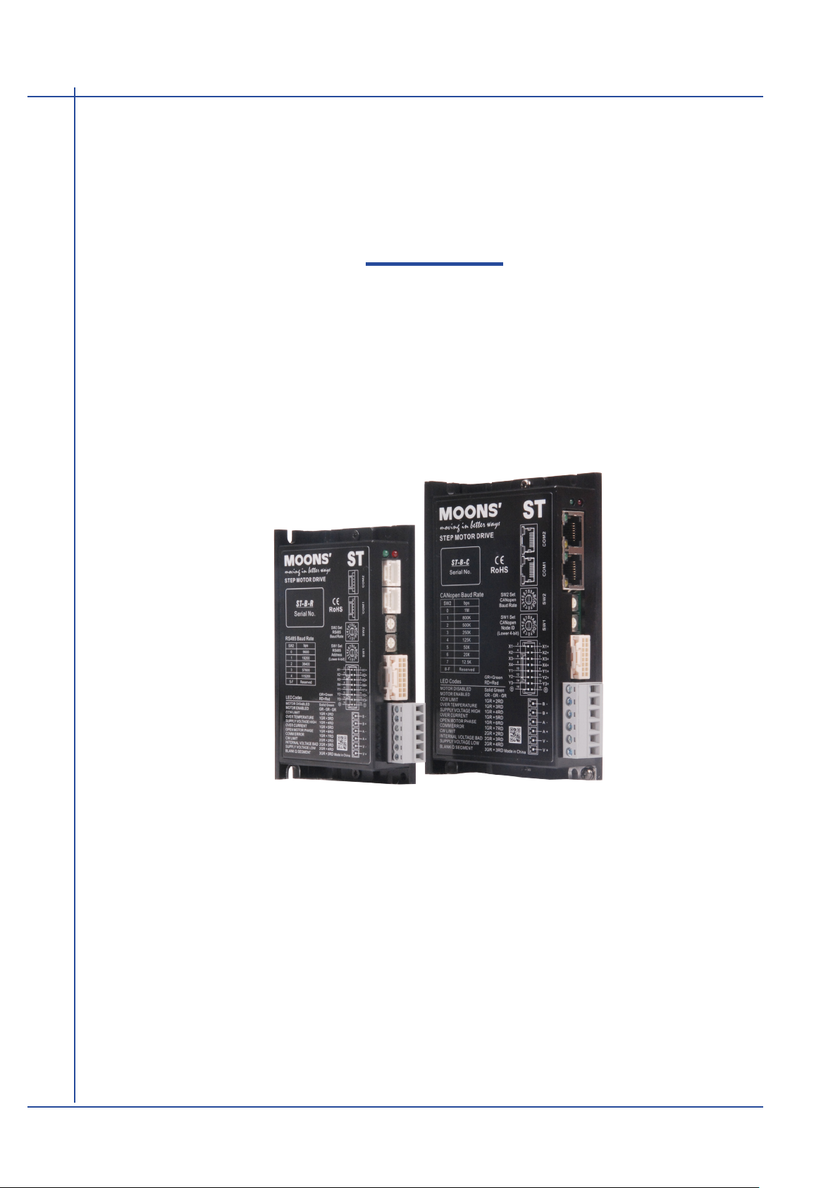
STB
Stepper Motor Drive
Hardware Manual
MSSTB05-R MSSTB10-R
MSSTB05-C MSSTB10-C
SHANGHAI AMP & MOONS’AUTOMATION CO.,LTD.
Rev. 1.0
09/06/2015
Page 2
MSSTB-R/C Hardware Manual
Contents
1 Introduction .................................................................................. 3
1.1 Features ............................................................................................. 3
1.2 Block Diagram ...................................................................................4
1.3 Safety Instructions .............................................................................5
2 Getting Started ............................................................................ 6
2.1 Installing Software .............................................................................7
2.2 Connecting communication (-R model) .............................................8
2.3 Connecting communication (-C model) ...........................................10
2.4 Setting bus address and baud rate .................................................. 11
2.4.1 RS-485 address and baud rate settings(-R model) .............................. 11
2.4.2 CANopen address and baud rate settings(-C model) ..........................12
2.5 Connecting the Power Supply .........................................................13
2.6 Choosing A Power Supply ...............................................................14
2.6.1 Voltage ................................................................................................14
2.6.2 Current .................................................................................................14
2.7 Connecting the motor ......................................................................15
3 Inputs and Outputs .................................................................... 15
3.1 Digital Inputs ....................................................................................16
3.1.1 X1,X2,X3,X4 digital input signal ...........................................................16
3.2 Digital Outputs .................................................................................17
3.2.1 Y1, Y2, Y3 Digital Outputs .................................................................... 17
4 Mounting the Drive .................................................................... 18
5 Reference Materials .................................................................. 19
5.1 Drive Mechanical Outlines ...............................................................19
5.2 Technical Specications ................................................................... 20
5.3 Recommended Motor ......................................................................21
5.4 Torque Curves .................................................................................22
5.5 Numbering System .................................................................. 24
5.6 Ordering Information ........................................................................ 24
6 Accessories (Sold Separately) ......................................................... 24
7 Contacting MOONS’ ..................................................................25
This User Manual is only applicable to the following models.
Model
MSSTB05-R
MSSTB10-R
MSSTB05-C
MSSTB10-C
Rev. 1.0
09/06/2015
Communication
RS-485 CANopen
2
400-820-9661
Page 3
MSSTB-R/C Hardware Manual
1 Introduction
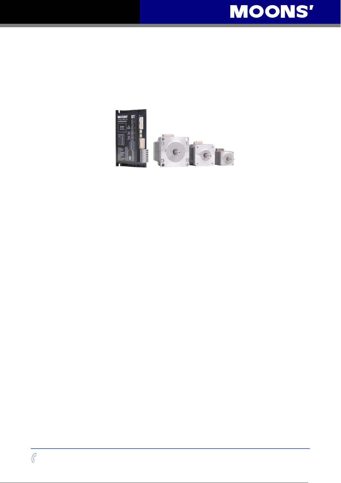
Thank you for selecting the MOONS’STB series stepper drive. The STB series are high
performance fieldbus control stepper drive which also integrates with built-in motion controller. The
drives can be controlled by SCL, Modbus/RTU or CANopen in real time. Motion profiles can also
be programmed and stored in drives (Q Program) and then be triggered by SCL, Modbus/RTU or
CANopen commands. The drives support RS-485/422 or CANopen communication.
1.1 Features
• Programmable, filed bus controlled stepper motor drive in compact package
• Operating DC voltage range:
MSSTB05 24-48V
MSSTB10 24-70V
• Control Mode
SCL
* Serial Communication Command
Q program
* Stand-Alone operation mode
Modbus/RTU (-R model only)
CANopen(-C model only)
* Compliant with CiA301 and CiA402 standanrd
• Communication
-R: Dual port RS-485/422
-C: Dual port CANopen, RS-232 included
• MSSTB05 output current: max 5A/phase (peak-of-sine)
• MSSTB10 output current: max 10A/phase (peak-of-sine)
• I/O
4 optically isolated digital inputs, 5-24VDC
3 optically isolated digital outputs, max30V/100mA
400-820-9661
3
Rev. 1.0
09/06/2015
Page 4
MSSTB-R/C Hardware Manual
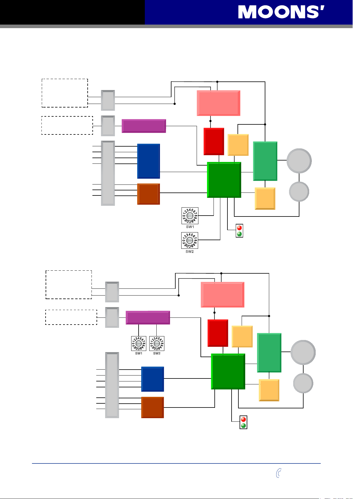
1.2 Block Diagram
MSSTB - R
Block Diagram
MSSTB05 24 - 48VDC
MSSTB10 24 - 70VDC
External
Power Supply
+
-
Conn
Power
5 Volt DC
Power Supply
RS-485
RX+,RX-,TX+,TX-,GND
MSSTB05 24 - 48VDC
MSSTB10 24 - 70VDC
External
Power Supply
Comm
X1
X2
X3
X4
Y1
Y2
Y3
MSSTB - C
Block Diagram
+
-
Conn
RS-485
I/O Connector
Conn
Power
Optical
ISO
Optical
Iso
RS-485
address
RS-485
baud rate
3.3VDC
Internal
Logic
Supply
Voltage
Temp
Detect
MOSFET
PWM
Power
motor
Amplifier
DSP
Driver
Controller
Over
Current
Detect
encoder
Status
W1
S
S
2
W
5 Volt DC
Power Supply
RX,TX,GND,CAN_H,CAN_L
Rev. 1.0
09/06/2015
CANopen
X1
X2
X3
X4
Y1
Y2
Y3
Conn
Comm
CANopen
Node ID
S
I/O Connector
W1
ARM
Optical
ISO
Optical
Iso
3.3VDC
Internal
CANopen
Baud rate
S
W2
Logic
Supply
Voltage
Temp
Detect
MOSFET
PWM
Power
motor
Amplifier
DSP
Driver
Controller
Over
Current
Detect
encoder
Status
4
400-820-9661
Page 5

MSSTB-R/C Hardware Manual
1.3 Safety Instructions
Only qualified personnel should transport, assemble, install, operate, or maintain this equipment.
Properly qualified personnel are persons who are familiar with the transport, assembly, installation,
operation, and maintenance of motors, and who meet the appropriate qualifications for their jobs.
To minimize the risk of potential safety problems, all applicable local and national codes regulating
the installation and operation of equipment should be followed. These codes may vary from area
to area and it is the responsibility of the operating personnel to determine which codes should be
followed, and to verify that the equipment, installation, and operation are in compliance with the
latest revision of these codes.
Equipment damage or serious injury to personnel can result from the failure to follow all applicable
codes and standards. MOONS’ does not guarantee the products described in this publication
are suitable for a particular application, nor do they assume any responsibility for product design,
installation, or operation.
• Read all available documentation before assembly and operation. Incorrect handling of the
products referenced in this manual can result in injury and damage to persons and machinery.
All technical information concerning the installation requirements must be strictly adhered to.
• It is vital to ensure that all system components are connected to earth ground. Electrical safety
is impossible without a low-resistance earth connection.
• This product contains electrostatically sensitive components that can be damaged by incorrect
handling. Follow qualified anti-static procedures before touching the product.
• During operation keep all covers and cabinet doors shut to avoid any hazards that could
possibly cause severe damage to the product or personal health.
• During operation, the product may have components that are live or have hot surfaces.
• Never plug in or unplug the Integrated Motor while the system is live. The possibility of electric
arcing can cause damage.
Be alert to the potential for personal injury. Follow recommended precautions and safe operating
practices emphasized with alert symbols. Safety notices in this manual provide important
information. Read and be familiar with these instructions before attempting installation, operation,
or maintenance. The purpose of this section is to alert users to the possible safety hazards
associated with this equipment and the precautions necessary to reduce the risk of personal injury
and damage to equipment. Failure to observe these precautions could result in serious bodily
injury, damage to the equipment, or operational difficulty.
400-820-9661
5
Rev. 1.0
09/06/2015
Page 6

MSSTB-R/C Hardware Manual
2 Getting Started
The following items are needed:
• A 24-48VDC power supply (24-70VDC power supply for MSSTB10), see the section below
entitled“Choose a Power Supply”for help in choosing the right one.
• A compatible stepper motor, please see the section below entitled “Recommended Motor”
• A small flat blade screwdriver for tightening the connectors screw(included)
• A PC running Microsoft Windows XP / Vista / Windows 7/ Windows 8(32-bit or 64-bit)operation
system
• Install STB Congurator software (Available from MOONS’website)
• -R model
For MSSTB05-R drive, a RS-485 daisy chain communication cable is included in the package.
It is used for connection with the next drive in the RS-485 network. It can also be used for
connection with PC for drive configuration.
For MSSTB10-R drive, a network cable is included in the package. It is used for connection
with the next drive in the RS-485 network. It can also be used for connection with PC for drive
configuration.
• -C model
A RS-232 programming cable(included in the package)
For MSSTB05-C drive, a CANopen daisy chain communication cable is included in the
package. It is used for connection with the next drive in the CANopen network.
For MSSTB10-C drive, a network cable is included in the package. It is used for connection
with the next drive in the CANopen network.
TIP: When connecting the rst drive in the RS-485 or CANopen network with PC or controller. you
can cut the daisy chain cable or network cable into two: one half is used for connection with the
RS-485 or CANopen port on the PC or controller, the other half can be used for connection with
termination resistor, which can be put at the end of the network.
Rev. 1.0
09/06/2015
6
400-820-9661
Page 7
MSSTB-R/C Hardware Manual
2.1 Installing Software
• Download the STB Congurator Software from the MOONS’ website and install it.
• Launch the software by clicking Start-----Programs ----MOONS’
• Connect the drive to the PC using communication cable:
Connect the -R model drive to the RS-485 port of the PC using the daisy chain cable or
network cable included in the package
Connect the -C model drive to the RS-232 port of the PC using the RS-232 cable included in
the package
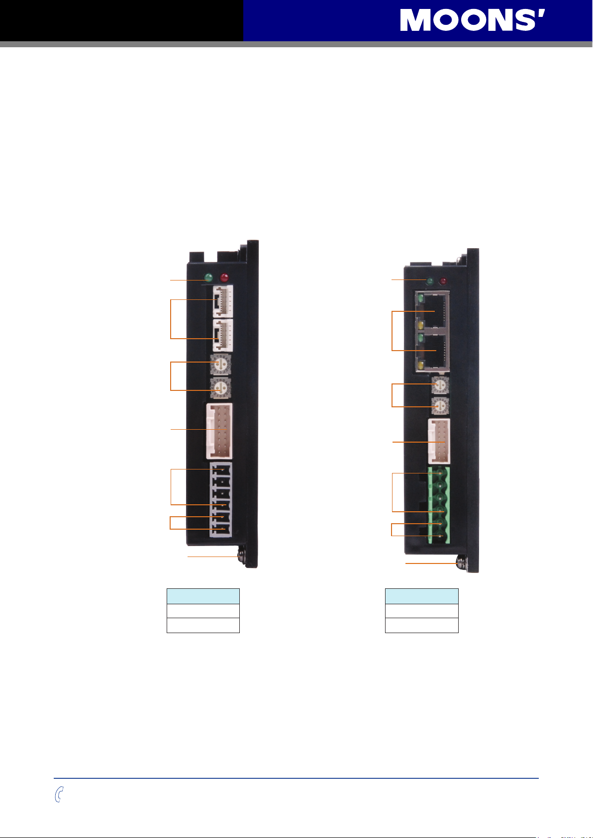
The connectors and other points of interest are illustrated below:
LED
Communication
Conncteor
SW2
SW1
I/O Connector
Motor Connector
Power Connector
Ground Screws
LED
Communication
Conncteor
SW2
SW1
I/O Connector
Motor Connector
Power Connector
Ground Screws
400-820-9661
Model number
MSSTB05-R MSSTB10-R
MSSTB05-C MSSTB10-C
Model number
7
Rev. 1.0
09/06/2015
Page 8
MSSTB-R/C Hardware Manual
1 8
1 8
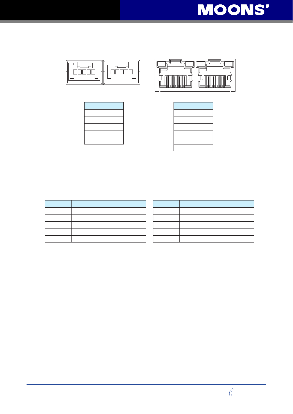
2.2 Connecting communication (-R model)
MSSTB05-R RS-485 Port MSSTB10-R RS-485 Port
1 5 1 5
PIN Signal
1 RX+
2 RX-
3 TX+
4 TX-
5 GND
PIN Signal
1 RX+
2 RX-
3 TX+
4.5 NC
6 TX-
7.8 GND
Connection STB drive with PC using RS-485 communication
Before using STB congurator for –R drive conguration, please connect COM1 or COM2 on the
driver to host PC by RS-485 daisy chain cable or network cable provided. Both 4 wire connection
or 2 wire connection can be used.
RS-485 four-wire connection: RS-485 two-wire connection:
Drive Connection
RX+ Connect to host’s TX+
RX- Connect to host’s TX-
TX+ Connect to host’s RX+
TX- Connect to host’s RX-
GND Connect to host’s GND
Drive Connection
RX+ Connect to host’s +
RX- Connect to host’s -
TX+ Connect to host’s +
TX- Connect to host’s -
GND Connect to host’s GND
NOTE: The RS-485 port on the drive is isolated from internal circuitry of the drive. So the
GND of each drive's RS-485 port must be connected together. The rst drive's GND of the
RS-485 port must be connected to the GND of RS-485 port on the host PC or controller.
Rev. 1.0
09/06/2015
8
400-820-9661
Page 9

MSSTB-R/C Hardware Manual
RS-485 network connection
Multiple –R model drive network can be built via dual RS-485 communication port by daisy chain
cable or network cable provided.
RS-485 Four-wire Configuration
RS-485 four-wire system utilize separate transmit and receive wires. One pair of wires connect
the host’s transmit signals(TX+/TX-) to each drive’s RX+/RX- receive terminals. The other pair
connects the drive’s TX+/TX- terminals to the host’s receive signals. A logical ground terminal is
provided on each drive and can be used to keep all the drives at the same ground potential. The
rst drive’s logical GND of the RS-485 bus must connect to host’s ground.
Four-wire Connection
Connect the drive’s RX+ to the TX+ terminal of the host controller,and connect the drive’s RX- to
the TX- terminal of the host controller . Connect the drive’s TX+ to the RX+ terminal of the host
controller,and connect the drive’s TX- to the RX- terminal of the host controller .
Connect the drive’s GND and the host’s GND to a same ground.
NOTE: The RS-485 port on the drive is isolated from internal circuitry of the drive. So the
GND of each drive’s RS-485 port must be connected together. The rst drive’s GND of the
RS-485 port must be connected to the GND of RS-485 port on the host PC or controller.
RS-485 Tow-wire Configuration
In a two-wire system ,the data transmitting and receiving use a same cable. the host must stop
its transmitting before receiving data. That means the host must stop transmit data before drive
begins to answer a query which just come from the host, otherwise the host cannot receive
any data witch sent from a drive. There is a transmit delay parameter that can be adjusted to
compensate for a host that is slow to disable its transmitter. This adjustment can be set over the
network using the TD command,it also can be set by using the STB Congurator software. Users
can set a shorter transmit delay in a four-wire system.
Two-wire connection
The RX+ and TX+ of the drive connect to the host’s + in parallel. The RX- and TX- of the drive
connect to the host’s - in parallel. Connect the drive’s GND and the host’s GND to a same ground.
NOTE: The RS-485 port on the drive is isolated from internal circuitry of the drive. So the
GND of each drive’s RS-485 port must be connected together. The rst drive’s GND of the
RS-485 port must be connected to the GND of RS-485 port on the host PC or controller.
400-820-9661
9
Rev. 1.0
09/06/2015
Page 10
MSSTB-R/C Hardware Manual
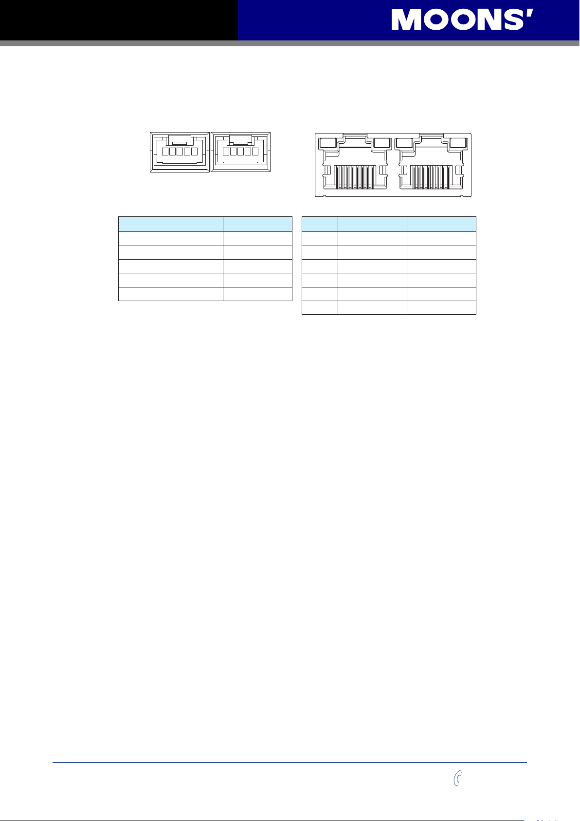
2.3 Connecting communication (-C model)
MSSTB05-C COM Port MSSTB10-C COM Port
COM1 COM2
1 5 1 5
PIN COM1 Signal COM2 Signal
1 RS-232_TX NC
2 RS-232_RX NC
3 CAN_H CAN_H
4 CAN_L CAN_L
5 GND GND
3,7,8 GND GND
COM1 COM2
1818
PIN COM1 Signal COM2 Signal
1 CAN_H CAN_H
2 CAN_L CAN_L
4 RS-232_TX NC
5 RS-232_RX NC
6 NC NC
PC connection with RS-232 cable
Before using STB congurator for –C drive configuration, please connect COM1 on the driver to
host PC by RS-232 programming cable.
CANopen network connection
Multiple –C model drive network can be built via dual CANopen communication port by daisy
chain cable or network cable provided.
NOTE: The CANopen port on the drive is isolated from internal circuitry of the drive. So the
GND of each drive’s CANopen port must be connected together. The rst drive’s GND of
the CANopen port must be connected to the GND of CANopen port on the controller.
Rev. 1.0
09/06/2015
10
400-820-9661
Page 11
MSSTB-R/C Hardware Manual
2.4 Setting bus address and baud rate
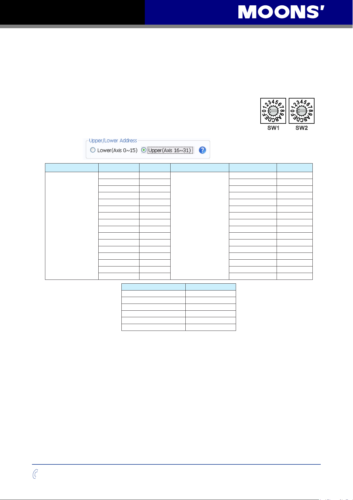
MSSTB drives have two rotary switches to set the bus address and baud rate.
2.4.1 RS-485 address and baud rate settings(-R model)
Set drive’s RS-485 address by rotary switch SW1
Set drive’s RS-485 baud rate by rotary switch SW2
RS-485
address
SW1 is used to set drive’s RS-485 address, and the range is 0~F (0~15
in decimal). If you want to set the drive’s RS-485 address range to 10~1F
1
W
(16~31 in decimal), you need to congure it in STB Congurator software.
Upper/Lower addr SW1 position SCL addr Upper/Lower addr SW1 position SCL addr
0 0
1 1 1 !
2 2 2 "
3 3 3 #
4 4 4 $
5 5 5 %
6 6 6 &
Lower(Axis 0~15)
7 7 7 '
8 8 8 (
9 9 9 )
A : A *
B ; B +
C < C ,
D = D E > E .
F ? F /
Upper(Axis 16~31)
S
0 @
RS-485
baud rate
2
S
W
SW2 position Baud Rate (bps)
0 9600
1 19200
2 38400
3 57600
4 115200
5-F Reserved
400-820-9661
11
Rev. 1.0
09/06/2015
Page 12
MSSTB-R/C Hardware Manual
2.4.2 CANopen address and baud rate settings(-C model)
Set drive’s CANopen address by rotary switch SW1
Set drive’s CANopen baud rate by rotary switch SW2
CANopen
address
CANopen
baud rate
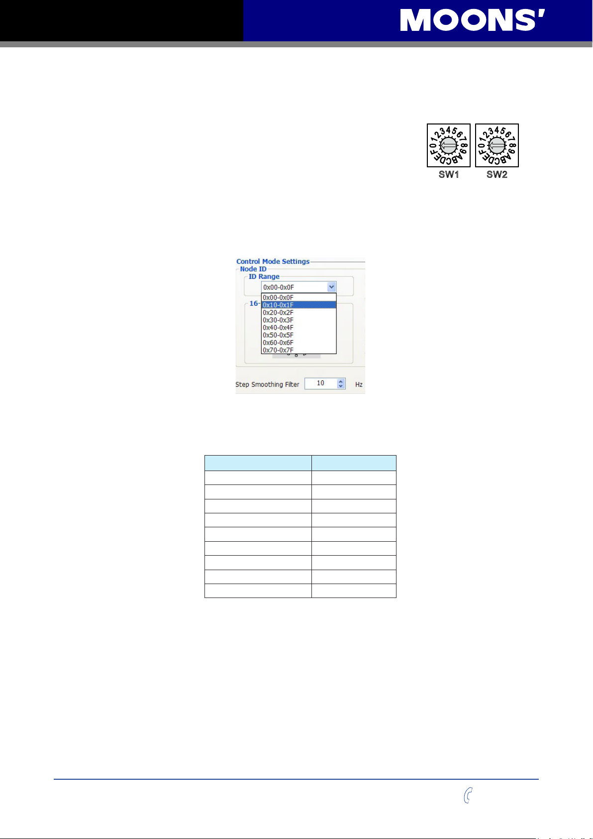
Each node on a CANopen network must have a unique Node ID. Valid
ranges for the Node ID are 0x01 through 0x7F (1~127). Node ID 0x00
1
W
S
2
S
W
is reserved in accordance with CiA301. The Node ID is selected using
rotary switches and software; one sixteen position switch set the lower four bits (0~F) of node ID,
while upper three bits of node ID are congured by STB Congurator software. Each time when
Node ID is changed, a power cycle is required before the new Node ID is valid.
Please refer to the CANopen manual for more information.
CANopen Baud Rate
There are 8 types of baud rate supported by CANopen communication on MSSTB drive. It is set
via SW2 switch on the drive
SW2 position Baud Rate (bps)
0 1M
1 800K
2 500K
3 250K
4 125K
5 50K
6 20K
7 12.5K
8-F Reserved
Rev. 1.0
09/06/2015
12
400-820-9661
Page 13
MSSTB-R/C Hardware Manual
2.5 Connecting the Power Supply
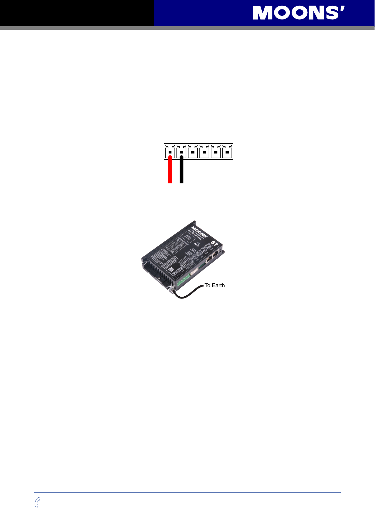
Connect power supply “+” terminal to the drive terminal labeled “V+”.
Connect power supply “-” terminal to the drive terminal labeled “V-”.
MSSTB05 accepts DC voltage range from 24 – 48VDC
MSSTB10 accepts DC voltage range from 24 – 70VDC
Warning: DO NOT reverse the wires
NOTE: DO NOT apply power until all connections to the drive have been made
V+J1V-
Power Connector
Ensure a proper earth ground connection by using the screw on the left side of the chassis.
To Earth Ground
Please read “choosing a power supply” for more details.
400-820-9661
13
Rev. 1.0
09/06/2015
Page 14
MSSTB-R/C Hardware Manual
2.6 Choosing A Power Supply
The main considerations when choosing a power supply are the voltage and current requirements
of the application.
2.6.1 Voltage
The MSSTB drive and motor is designed to give optimum performance between 24~48 Volts DC.
Choosing the voltage depends on the performance needed and diver/motor heating that
acceptable and/or does not cause a drive over-temperature. Higher voltage will give higher speed
performance,but will cause the drive to produce higher temperatures. Using power supplies with
voltage outputs that are near the drive maximum may signicantly reduce the operational duty-
cycle.
The MSSTB drive extended range of operation can be as low as 18VDC minimum to as high as
75VDC maximum. (18-53VDC for MSSTB05 Drives) When operation below 18VDC, the MSSTB
series will work unstable. The supply input cannot go blow 18VDC for reliable operation, otherwise
under voltage alarm will be triggered. MSSTB drive will stop working when this alarm is triggered.
MSSTB05
If a regulated power supply is used,and that is near the driver maximum voltage of 53VDC ,a
voltage clamp may be required to prevent the voltage over 53VDC which will occurs a over-voltage
fault. When using an unregulated power supply, make sure the no-load voltage of the supply does
not exceed the maximum input voltage 53VDC.
MSSTB10
If a regulated power supply is used,and that is near the driver maximum voltage of 75VDC ,a
voltage clamp may be required to prevent the voltage over 75VDC which will occurs a over-voltage
fault. When using an unregulated power supply, make sure the no-load voltage of the supply does
not exceed the maximum input voltage 75VDC.
2.6.2 Current
When MSSTB drives work with different motors, the recommended power supply output current
capacity under different supply voltage is shown in below table. The MSSTB drive power supply
current is lower than the the winding currents because it uses switching ampliers to convert a high
voltage and low current into low voltage and high current. The more power supply voltage exceeds
the motor voltage,the less current will be required from the power supply.
It is important to note that the current draw is signicantly different at higher speeds depending
on the torque load to the motor. Estimating how much current is necessary may require a good
analysis of the load to the motor.
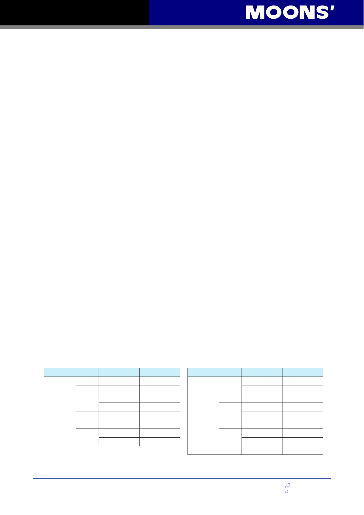
Drive Motor Voltage Current Drive Motor Voltage Current
MSSTB05
AM11 24V above 1A
AM14 24V above 1A 48V above 4A
AM17
AM23
AM24
24V above 1.5A 70V above 4A
48V above 1.5A
24V above 3A 48V above 4.5A
48V above 4A 70V above 4.5A
24V above 4.5A
48V above 4.5A 48V above 6A
MSSTB10
AM23
AM24
AM34
24V above 3A
24V above 4.5A
24V above 6A
70V above 6A
Rev. 1.0
09/06/2015
14
400-820-9661
Page 15
MSSTB-R/C Hardware Manual
2.7 Connecting the motor
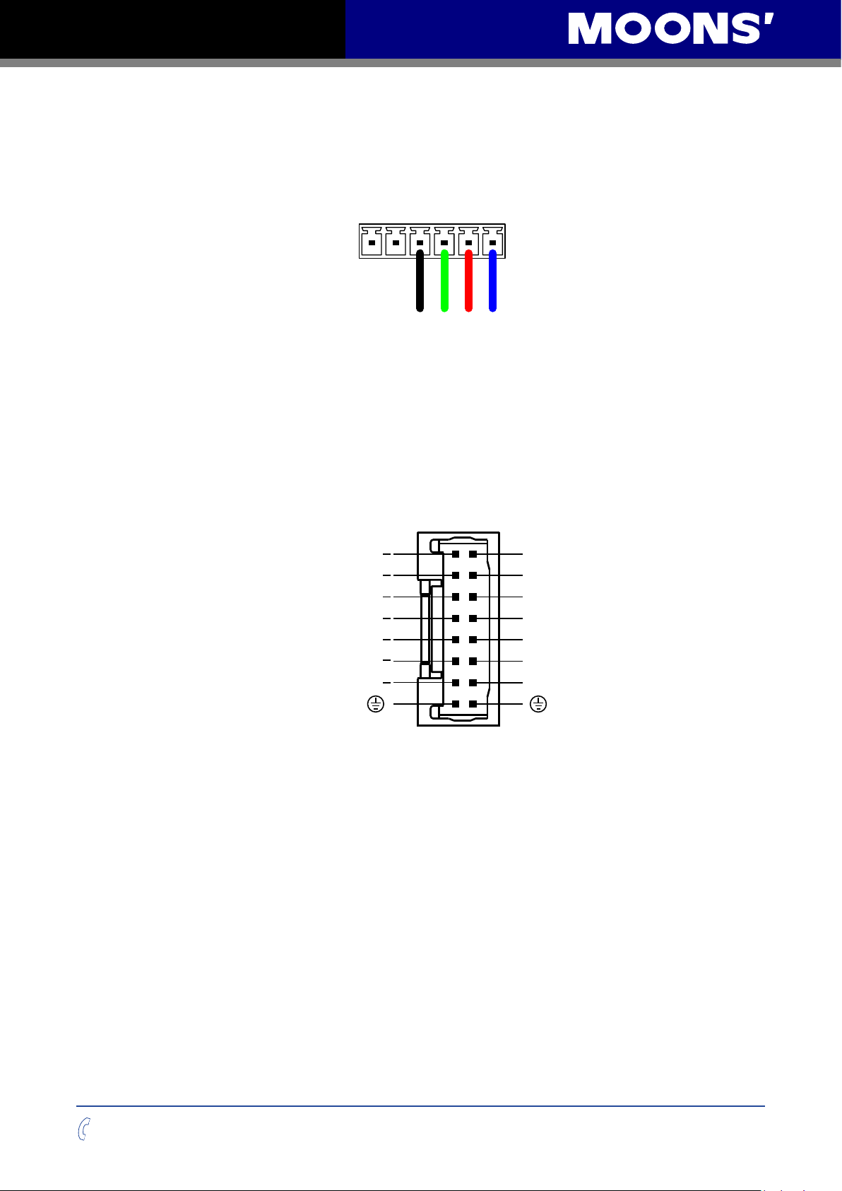
For MOONS’stepper motor, please connect black, green, red, blue wires to drive’s A+, A-, B+
and B- correspondingly.
A+J1A- B+ B-
Motor Connector
If using a non-MOONS’motor, please refer to your motor specs for wiring information.
3 Inputs and Outputs
MSSTB05/10-R/C inputs and outputs include:
• 4 optically isolated digital inputs, 5-24VDC for high level voltage
• 3 optically isolated digital outputs, maximum voltage 30V, maximum sinking or sourcing current
100mA
J2
X1
X2
X3
X4
Y1
Y2
Y3
-
-
-
-
-
-
-
2
4
6
8
1 0
1 2
1 4
1 6
1
3
5
7
9
1 1
1 3
1 5
X1+
X2+
X3+
X4+
Y1+
Y2+
Y3+
I/O Connector Diagram
400-820-9661
15
Rev. 1.0
09/06/2015
Page 16
MSSTB-R/C Hardware Manual
3.1 Digital Inputs
3.1.1 X1,X2,X3,X4 digital input signal
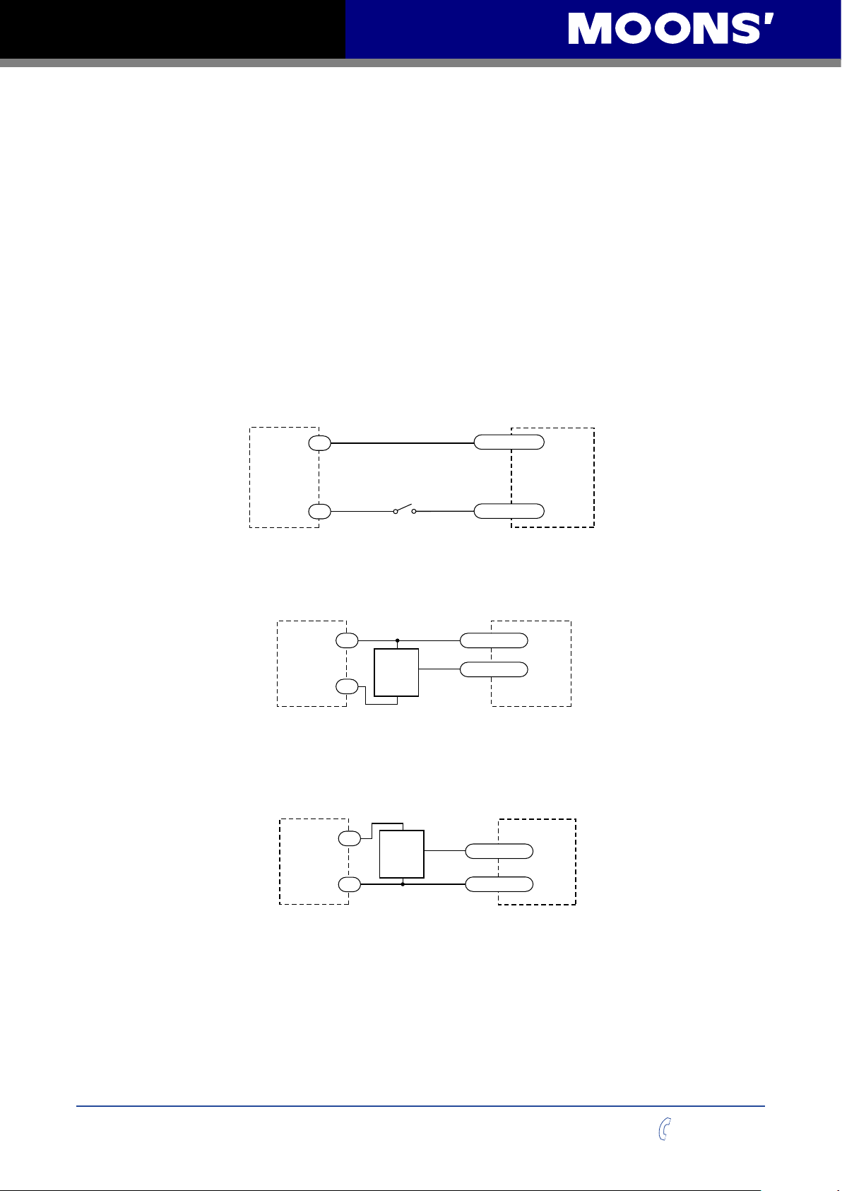
X1, X2: optically isolated, differential, 5-24VDC, minimum pulse width 250ns, maximum pulse
frequency 2MHz
X3, X4: optically isolated, differential, 5-24VDC, minimum pulse width 50μs, maximum pulse
frequency 10KHz
X1 can be used as CW limit input or general purpose input.
X2 can be used as CCW limit input or general purpose input.
X3 can be used as motor enable input or general purpose input.
X4 can be used as alarm reset input or general purpose input.
Please use STB Configurator software for X1,X2,X3 and X4 function configuration.
Following graphs shows some common connection methods for the inputs:
5-24
VDC
Power
Supply
+
Switch or Relay
(closed = logic Low)
-
X1/2/3/4+
X1/2/3/4-
Connecting the inputs to a Switch or Relay
5-24
VDC
Power
Supply
+
+
NPN
Output
-
output
–
X1/2/3/4+
X1/2/3/4-
Connecting the inputs to a NPN type output
5-24
VDC
Power
Supply
+
-
+
PNP
Output
–
output
X1/2/3/4+
X1/2/3/4-
MSSTB
Drive
MSSTB
Drive
MSSTB
Drive
Rev. 1.0
09/06/2015
Connecting the inputs to a PNP type output
16
400-820-9661
Page 17
MSSTB-R/C Hardware Manual
3.2 Digital Outputs
3.2.1 Y1, Y2, Y3 Digital Outputs
• Y1 can be used as alarm output or general purpose output.
• Y2 can be used as brake output or general purpose output.
• Y3 cab be used as motion output , tach output, timing signal output(50pulse/rev) or general
purpose output.
Please use STB Congurator software for Y1,Y2 and Y3 function conguration.
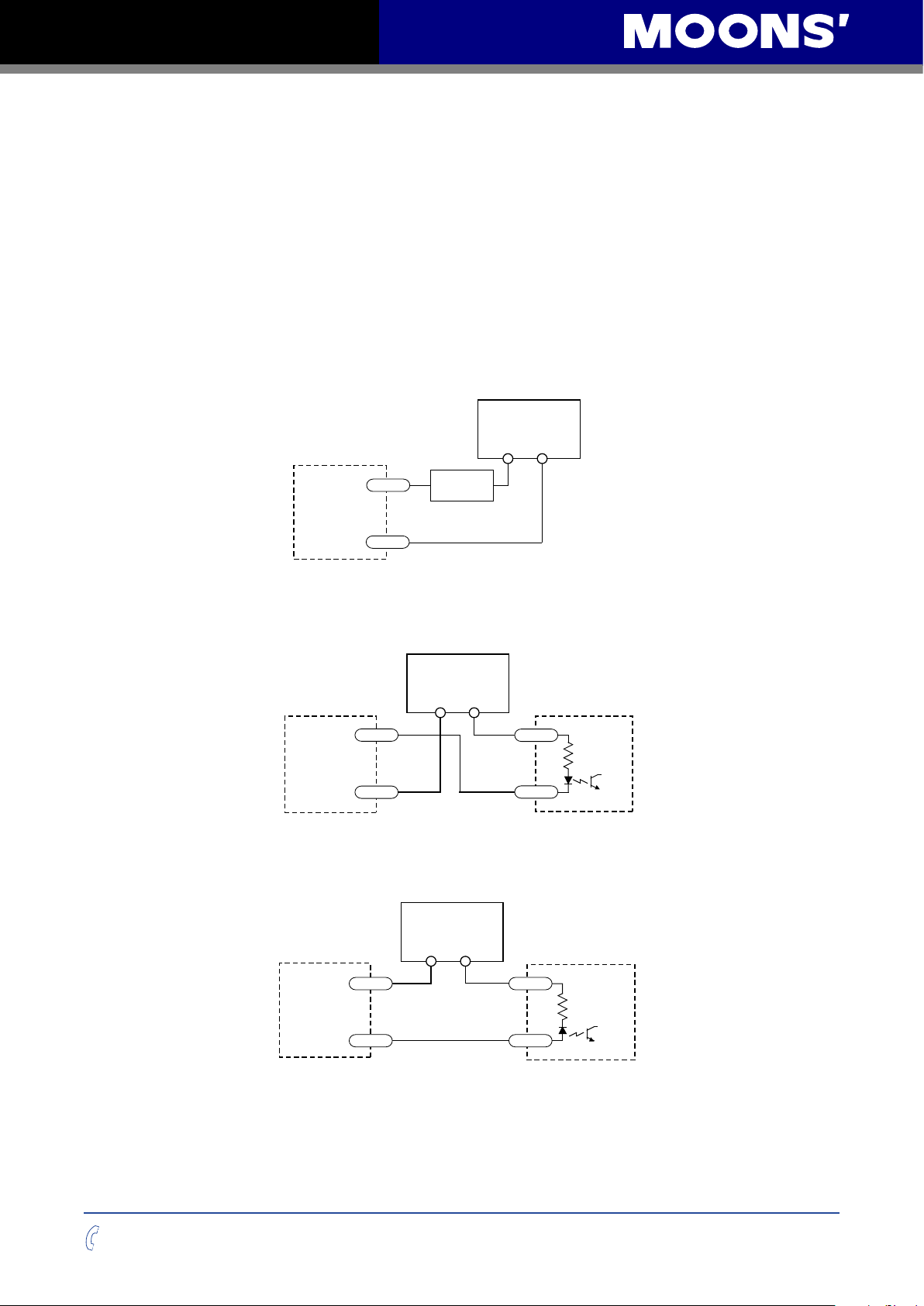
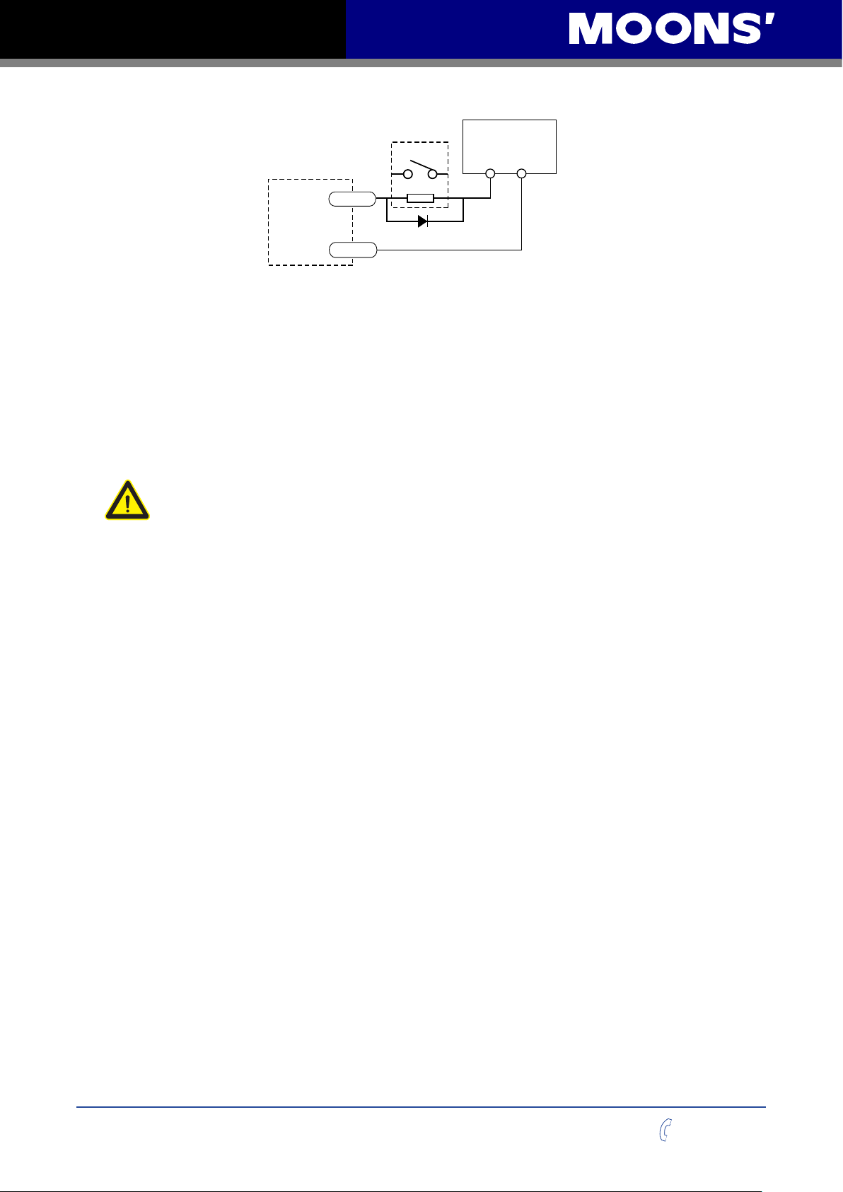
Following graphs shows some common connection methods for the outputs:
NOTE: Do not connect the outputs to more than 30VDC power supply. And the current of
each output terminal must not exceed 100mA.
5-24 VDC
Power Supply
+ –
Y1/2/3+
Load
MSSTB
Drive
Y1/2/3-
Connecting a sinking output
5-24 VDC
Power Supply
+
–
Y1/2/3+
MSSTB
COM
PLC
Drive
Y1/2/3-
Connecting a sinking output with PLC’s input
CDV 42-5
IN
ylppuS rewoP
400-820-9661
+ –
Y1/2/3+
COM
MSSTB
Drive
Y1/2/3-
Connecting a sourcing output with PLC’s input
IN
17
CLP
Rev. 1.0
09/06/2015
Page 18
MSSTB-R/C Hardware Manual
Connecting a sinking output
Connecting a sinking output with PLC’s input
Connecting a sourcing output with PLC’s input
MSSTB
Drive
5-24 VDC
Power Supply
+ –
Load
Y1/2/3-
Y1/2/3+
CLP
CDV 42-5
ylppuS rewoP
+ –
Y1/2/3-
Y1/2/3+
IN
COM
MSSTB
Drive
PLC
5-24 VDC
Power Supply
+
–
Y1/2/3-
Y1/2/3+
COM
IN
MSSTB
Drive
4 Mounting the Drive
Use the M3 or M4 screw to mount the MSSTB series drive .The drive should be securely fastened
to a smooth ,at metal surface the will help conduct heat away from the chassis. If this is not
possible, forced airow from a fan maybe required to prevent the drive from overheating.
• Never use the drive in a place where there is no air flow or the surrounding air is
• Never put the drive where it can get wet or where metal or other electrically
• Always provide air flow around the drive. When mounting multiple MSSTB drives
5-24 VDC
relay
Y1/2/3+
Power Supply
+ –
MSSTB
Drive
1N4935 suppression diode
Y1/2/3-
Driving a relay
more than 40℃.
conductive particle particles can get on the circuity.
near each other, maintain at least 2cm of space between drives.
Rev. 1.0
09/06/2015
18
400-820-9661
Page 19
MSSTB-R/C Hardware Manual
23.5
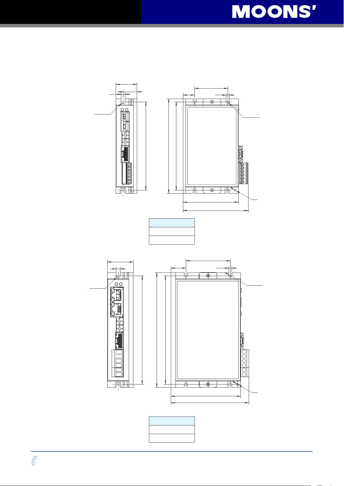
5 Reference Materials
5.1 Drive Mechanical Outlines
4.5
2-R2.25
15.5
99
99
106
Model
MSSTB05-R
MSSTB05-C
13
37
62
72.9
3.5
4-R1.75
M3
2-R2.25
4.5
29
122
16.6
122
129
Model
MSSTB10-R
MSSTB10-C
50
78.2
87.3
3.5
4-R1.75
M3
400-820-9661
19
Rev. 1.0
09/06/2015
Page 20
MSSTB-R/C Hardware Manual
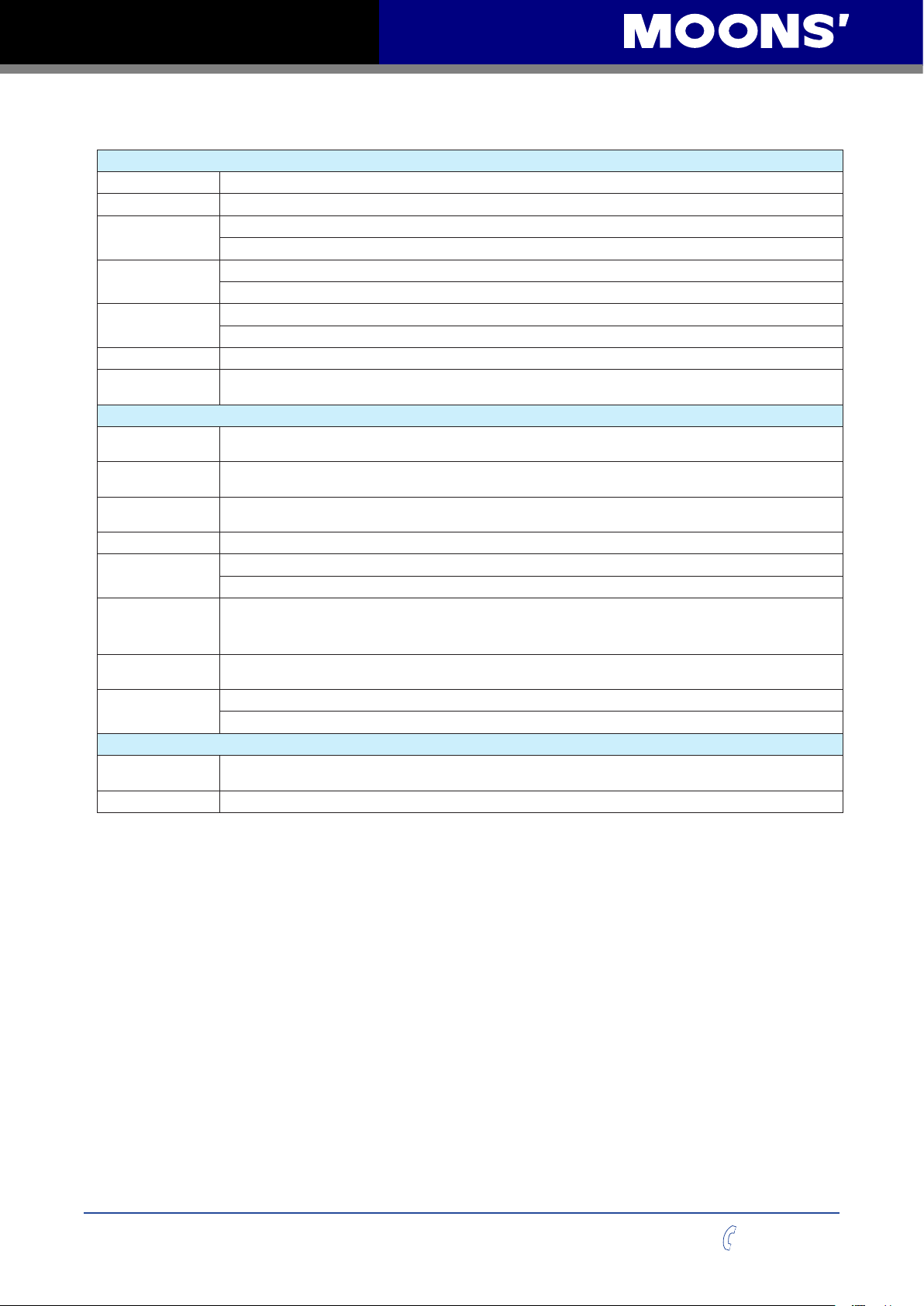
5.2 Technical Specifications
Power Amplifier
Amplier Type Dual H-Bridge, 4 Quadrant
Current Control 4 state PWM at 20 KHz
Output Current
voltage range
Input Voltage Range
Protection Over-voltage, under-voltage, over-temp, Over-current
Idle Current
Reduction
Anti-Resonance
Torque Ripple
Smoothing
Auto Test &
Auto Setup
Non-Volatile Storage Congurations are saved in FLASH memory on-board the DSP
Operation Mode
Digital Input
Digital Output
Communication Port
Ambient
Temperature
Humidity
MSSTB05: 0.1-5.0A/phase (peak-of-sine) in 0.01 amp increments
MSSTB10: 0.1-10.0A/phase (peak-of-sine) in 0.01 amp increments
MSSTB05: 24 - 48VDC
MSSTB10: 24 - 70VDC
MSSTB05: 18 - 53VDC
MSSTB10: 18 - 75VDC
Reduction range of 0 - 90% of running current after a delay selectable in milliseconds
Controller
Raises the system-damping ratio to eliminate midrange instability and allow stable operation throughout the
speed range of the motor
Allows for ne adjustment of phase current waveform harmonic content to reduce low-speed torque ripple in the
range of 0.25 to 1.5 rps
Auto test and setup at power on (ie. motor resistance, and capacitance) to optimize your system performance.
R Version: SCL, Q, Modbus
C Version: CANopen (CiA301 and CiA402 standard). Q program can also be triggered via CANopen Command
4 digital inputs:
X1, X2: Optically isolated, differential, 5-24VDC, minimum pulse width = 250ns, maximum pulse frequency = 2MHz
X3, X4: Optically isolated, differential, 5-24VDC, minimum pulse width = 50μs, maximum pulse frequency = 10KHz
3 digital Outputs
Y1, Y2, Y3: Optically isolated, 30V/100mA max
R model: dual port RS-485(MSSTB05: crimp style connector / MSSTB10: RJ45 connector)
C model: dual port CANopen (MSSTB05: crimp style connector / MSSTB10: RJ45 connector) RS-232 included
Physical
0 - 40°C when mounted to a suitable heat sink
90% non-condensing
Rev. 1.0
09/06/2015
20
400-820-9661
Page 21
MSSTB-R/C Hardware Manual
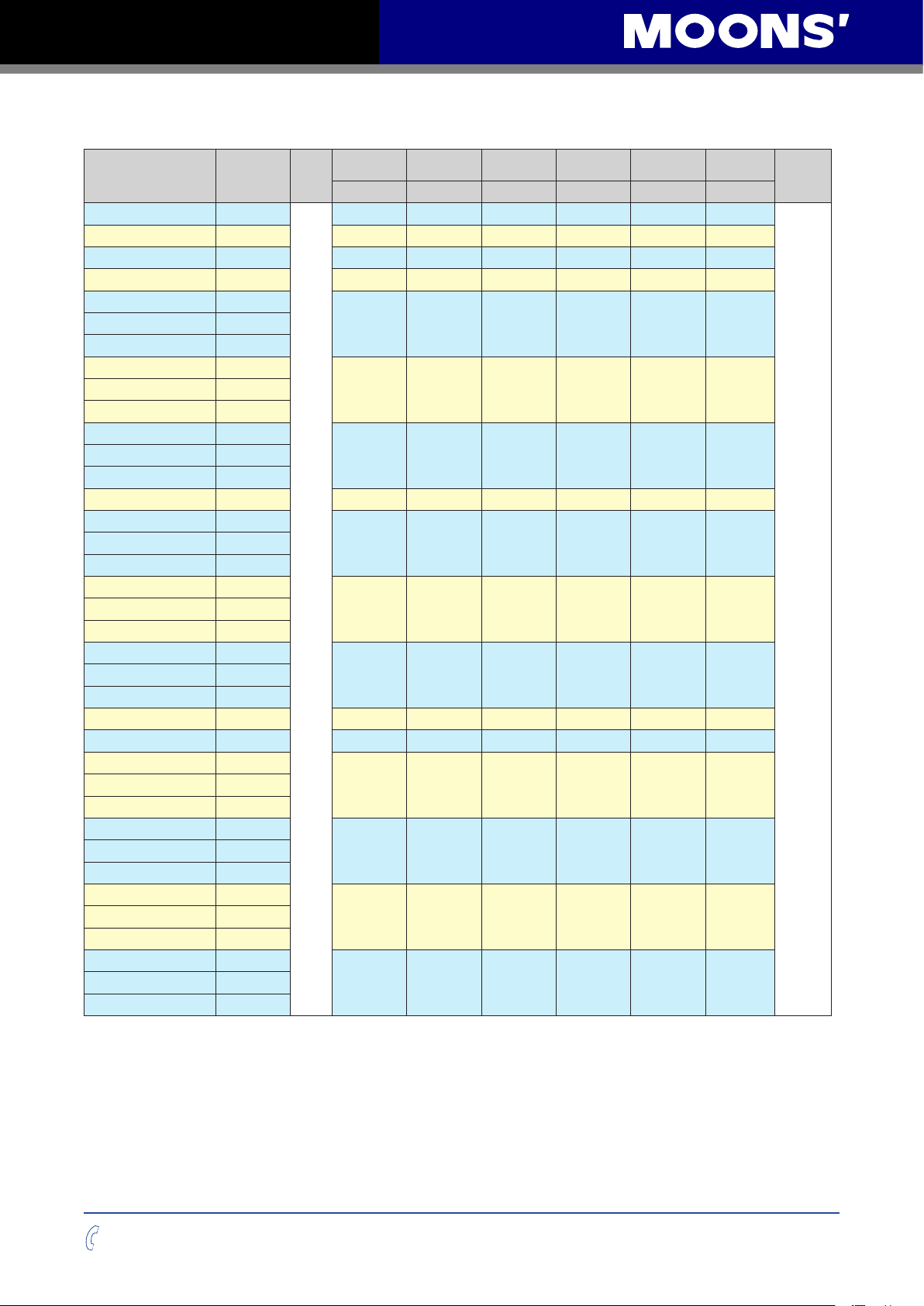
5.3 Recommended Motor
Model Shaft Leads
AM11HS1008-07
AM11HS3007-02
AM11HS5008-01
AM14HYB401-03
AM17HD4452-02N
AM17HD4452-E1000D
AM17HD2438-02N
AM17HD2438-E1000D
AM17HD6426-06N
AM17HD6426-E1000D
AM17HDB410-01N
AM23HS0421-01
AM23HS0421-E1000D
AM23HS2450-01
AM23HS2450-E1000D
AM23HS3455-01
AM23HS3455-E1000D
AM23HS5412-01
AM24HS2402-08N
AM24HS5401-10N
AM24HS5401-E1000D
AM34HD0404-08
AM34HD0404-E1000D
AM34HD1404-06
AM34HD1404-E1000D
AM34HD2403-07
AM34HD2403-08
AM34HD2403-E1000D
Single Shaft
Single Shaft
Single Shaft
Single Shaft
Single Shaft
Double Shaft
W/Encoder
Single Shaft
Double Shaft
W/Encoder
Single Shaft
Double Shaft
W/Encoder
Single Shaft
Single Shaft
Double Shaft
W/Encoder
Single Shaft
Double Shaft
W/Encoder
Single Shaft
Double Shaft
W/Encoder
Single Shaft
Single Shaft
Single Shaft
Double Shaft
W/Encoder
Single Shaft
Double Shaft
W/Encoder
Single Shaft
Double Shaft
W/Encoder
Single Shaft
Double Shaft
W/Encoder
Length“L”
mm N·m A/Phase Ω/Phase g·cm
31.0 0.05 1.6 2.5 9.0 0.1
40.0 0.08 1.6 1.7 12.0 0.15
51.0 0.12 1.6 3.5 18.0 0.2
40.0 0.2 1.0 4.3 20.0 0.21
34.3 0.25 1.8 1.5 38.0 0.23AM17HD4452-01N
39.8 0.4 1.8 1.9 57.0 0.28AM17HD2438-01N
48.3 0.5 1.8 2.3 82.0 0.36AM17HD6426-05N
62.8 0.8 1.6 2.6 123 0.6
41.0 0.6 4.5 0.48 135.0 0.42AM23HS0421-02
4
54.0 1.2 4.5 0.63 260.0 0.6AM23HS2450-02
76.0 1.8 4.5 0.75 460.0 1.0AM23HS3455-02
111. 0 3.2 4.5 1.2 750.0 1.5
54.0 1.2 4.5 0.43 450.0 0.83
85.0 2.5 4.5 0.65 900.0 1.4AM24HS5401-24N
66.5 3.0 7.0 0.24 1100.0 1.6AM34HD0404-09
96.0 5.0 7.0 0.33 1850.0 2.7AM34HD1404-07
125.5 7.1 7.0 0.49 2750.0 3.8
Holding
Torque
Current Resistance Rotor Inertia Motor Mass
2
Kg
Dielectric
Strength
500V AC
1 minute
400-820-9661
21
Rev. 1.0
09/06/2015
Page 22
MSSTB-R/C Hardware Manual
Torque(mN m)
Torque(mN m)
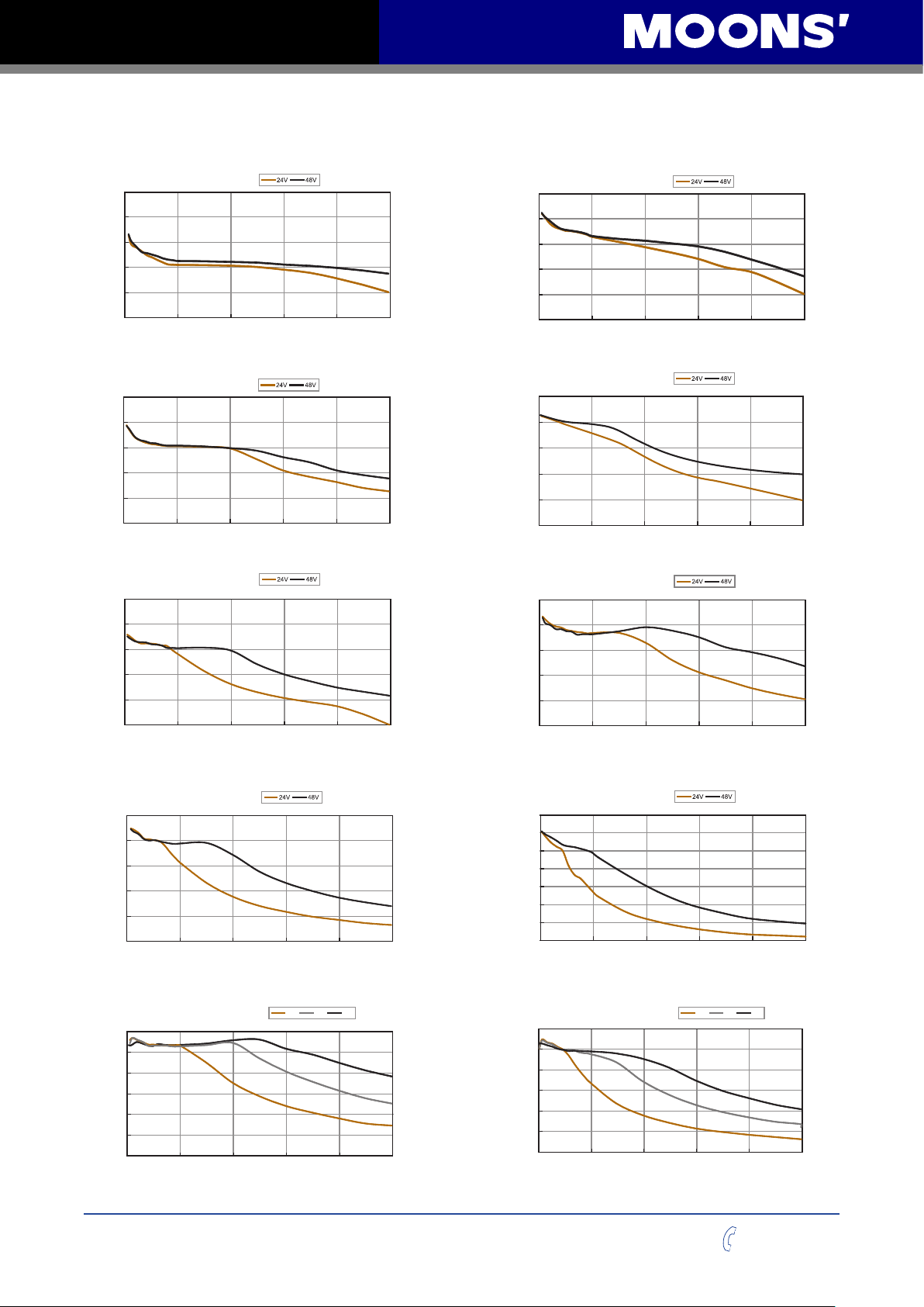
AM11HS5008
Torque(mN m)
AM17HD2438
Torque(mN m)
AM17HDB410
)m N(euqroT
5.4 Torque Curves
AM11HS1008
Microstep20000 steps/rev
Current1.6APeak
100
80
.
60
40
20
0
01020304050
Microstep20000 steps/rev
Current1.6APeak
150
120
.
90
60
30
0
01020304050
Microstep20000 steps/rev
Current1.8APeak
500
400
.
300
200
100
0
01020304050
Speed(rps)
Speed(rps)
Speed(rps)
AM11HS3007
Microstep20000 steps/rev
Current1.6APeak
100
80
.
60
40
20
0
01020304050
AM14HYB401
Microstep20000 steps/rev
Current1.0APeak
150
120
.
90
60
Torque(mN m)
30
0
01020304050
AM17HD4452
Microstep20000 steps/rev
Current1.8APeak
250
200
.
150
100
Torque(mN m)
50
0
01020304050
Speed(rps)
Speed(rps)
Speed(rps)
AM17HD6426
Microstep20000 steps/rev
Current1.8APeak
500
400
.
300
200
Torque(mN m)
100
0
01020304050
AM23HS0421
Microstep20000 steps/rev
Current4.5APeak
0.6
0.5
.
0.4
0.3
0.2
0.1
0
010203040 50
Speed(rps)
Speed(rps)
48V
24V
75V
Rev. 1.0
09/06/2015
22
Microstep20000 steps/rev
Current1.6APeak
700
600
500
.
400
300
200
Torque(mN m)
100
0
01020304050
Speed(rps)
AM23HS2450
Microstep20000 steps/rev
Current4.5APeak
1.2
1
)m N(euqroT
.
0.8
0.6
0.4
0.2
0
010203040 50
Speed(rps)
24V
48V
75V
400-820-9661
Page 23
MSSTB-R/C Hardware Manual
)m N(euqroT
)m N(euqroT
)m N(euqroT
)
(euqroT
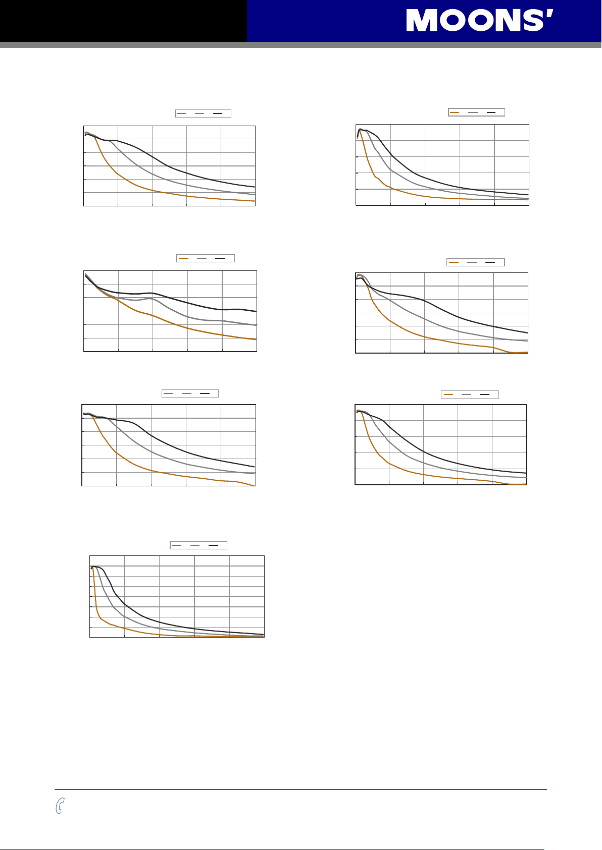
AM23HS3455
Microstep20000 steps/rev
Current4.5APeak
1.8
1.5
.
1.2
0.9
0.6
0.3
0
010203040 50
Speed(rps)
AM24HS2402
Microstep20000 steps/rev
Current4.5APeak
1.2
1
.
0.8
0.6
0.4
0.2
0
010203040 50
Speed(rps)
AM34HD0404
Microstep20000 steps/rev
Current7.0APeak
3.0
2.5
m N
.
2.0
24V
1.5
1.0
0.5
0
010203040 50
Speed(rps)
48V
24V
24V
48V
75V
75V
48V
75V
AM23HS5412
Microstep20000 steps/rev
Current4.5APeak
2.5
24V
2
.
1.5
1
0.5
0
010203040 50
Speed(rps)
AM24HS5401
Microstep20000 steps/rev
Current4.5APeak
2.4
2
)m N(euqroT
.
1.6
24V
1.2
0.8
0.4
0
010203040 50
Speed(rps)
AM34HD1404
Microstep20000 steps/rev
Current7.0APeak
5.0
24V
48V
4.0
.
3.0
2.0
Torque(N m)
1.0
0
010203040 50
Speed(rps)
48V
75V
75V
48V
75V
AM34HD2403
Microstep20000 steps/rev
Current7.0APeak
8.0
48V
24V
75V
7.0
)
6.0
m N
.
5.0
(euqroT
4.0
3.0
2.0
1.0
0
010203040 50
Speed(rps)
400-820-9661
23
Rev. 1.0
09/06/2015
Page 24
MSSTB-R/C Hardware Manual
L
L
8 1
8 1
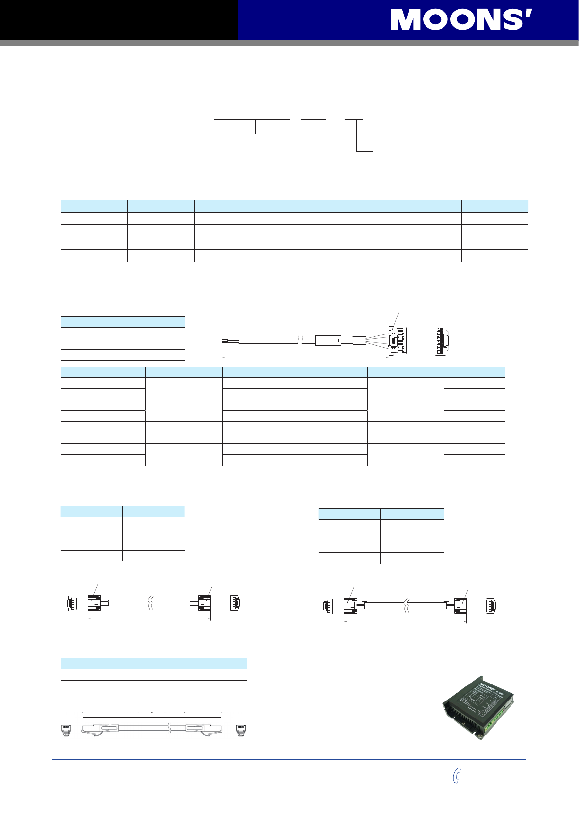
5.5 Numbering System
MSSTB 05 - R
MSSTB Series
Output Current
05 = 5A Peak
10 = 10A Peak
Communication
R = RS-485
C = CANopen
5.6 Ordering Information
Model Current Voltage
MSSTB05-R 0.1-5.0A 24-48VDC √ √ √
MSSTB10-R 0.1-10.0A 24-70VDC √ √ √
MSSTB05-C 0.1-5.0A 24-48VDC √ √
MSSTB10-C 0.1-10.0A 24-70VDC √ √
RS-485 Modbus/RTU CANopen Q Program
6 Accessories (Sold Separately)
I/O Cable
P/N Length
1008-030 0.3m
1008-100 1m
1008-200 2m
Pin No. Assignment Description Color Pin No. Assignment Description Color
1 X1+
2 X1- Black 10 Y1- Blue/Black
3 X2+
4 X2- Brown/Black 12 Y2- Green/Black
5 X3+
6 X3- Gray/Black 14 Y3- Yellow/Black
7 X4+
8 X4- White/Black 16 SHIELD black heat-shrink tube
X1 Digital Input
X2 Digital Input
X3 Digital Input
X4 Digital Input
30±3
Red 9 Y1+
Brown 11 Y2+
Gray 13 Y3+
White 15 SHIELD
L±5
Housing: 501646-1600(Molex)
Crimp: 501648-1000(Molex)
J1
Y1 Digital Output
Y2 Digital Output
Y3 Digital Output
Shiled
15
16
1 2
black heat-shrink tube
Blue
Green
Yellow
RS-485 Daisy Chain Cable
(MSSTB05-R Only)
P/N Length
2111-025 * 0.25m
2111-050 0.5m
2111-100 1m
2111-300 3m
* 2111-025 is included in the drive package.
Housing: ZER-05V-S(JST)
Crimp: SZE-002T-P0.3(JST)
5
J1
1
L±100
Housing: ZER-05V-S(JST)
Crimp: SZE-002T-P0.3(JST)
1
5
J2
RS-485 / CANopen Daisy Chain Cable
(MSSTB10-R / MSSTB10-C Only)
Common Type Flexible Type Length
2012-030 * 2013-030 0.3m
2012-300 2013-300 3m
* 2012-030 is included in the drive package.
CANopen Daisy Chain Cable
(MSSTB05-C Only)
P/N Length
2112-025 * 0.25m
2112-050 0.5m
2112-100 1m
2112-300 3m
* 2111-025 is included in the drive package.
Housing: ZER-05V-S(JST)
Crimp: SZE-002T-P0.3(JST)
5
J1
1
L±100
Housing: ZER-05V-S(JST)
Crimp: SZE-002T-P0.3(JST)
1
5
RC-880 Regeneration Clamp
RC-880 is used to limit increase in power supply voltage
when the motor is decelerating under load. This is
commonly referred to as "regeneration".
RC-880 can clamp the regeneration
and prevent the power supply and/or
drive being damaged or destroyed.
Connect the RC-880 between the
power supply and the drive.
Max. Supply Voltage: 80V
Max. Output Current: 8A(rms)
Continuous Power: 50W
J2
Rev. 1.0
09/06/2015
24
400-820-9661
Page 25
MSSTB-R/C Hardware Manual
MOONS’Headquarter
168 Mingjia Road, Minhang District, Shanghai 201107,
P.R. China
Tel: +86 (0)21 52634688
Fax:+86 (0)21 52634098
Domestic Offices
Shenzhen
Room 2209, 22/F, Kerry Center, 2008 Renminnan Road,
Luohu District, Shenzhen 518001, P.R. China
Tel: +86 (0)755 25472080
Fax:+86 (0)755 25472081
North America Company
MOONS’INDUSTRIES (AMERICA), INC.
1113 North Prospect Avenue, Itasca, IL 60143 USA
Tel: +1 630 8335940
Fax: +1 630 8335946
APPLIED MOTION PRODUCTS, INC.
404 Westridge Dr. Watsonville, CA 95076, USA
Tel: +1 831 7616555
Fax:+1 831 7616544
LIN ENGINEERING, INC.
16245 Vineyard Blvd., Morgan Hill, CA 95037
Tel: +1 408 9190200
Fax:+1 408 9190201
European Company
MOONS’ INDUSTRIES (EUROPE) S.R.L.
Via Torri Bianche n.1 20871 Vimercate(MB) Italy
Tel: +39 039 6260521
Fax: +39 039 9631409
Japan Company
MOONS’INDUSTRIES JAPAN CO., LTD.
Room 601, 6F, Shin Yokohama Koushin Building,
2-12-1, Shin-Yokohama, Kohoku-ku, Yokohama,
Kanagawa, 222-0033, Janpan
Tel: +81 (0)45 4755788
Fax: +81 (0)45 4755787
South-East company
MOONS’INDUSTRIES (SOUTH-EAST ASIA) PTE. LTD.
33 Ubi Avenue 3 #08-23 Vertex Singapore 408868
Tel: +65 66341198
Fax: +65 66341138
Nanjing
Room 1101-1102, Building 2,New Town Development
Center,No.126 Tianyuan Road ,Moling Street,
Jiangning District,Nanjing 211106, P.R. China
Tel: +86 (0)25 52785841
Fax:+86 (0)25 52785485
Qingdao
Room 1012, Zhuoyue Tower, No.16 Fengcheng Road,
Shibei District, Qingdao 26000, P.R. China
Tel: +86 (0)532 80969935
Fax:+86 (0)532 80919938
Beijing
Room 816, Tower B, China Electronics Plaza, 3 Danling
Street, Haidian District, Beijing 100080, P.R. China
Tel: +86 (0)10 58753312
Fax:+86 (0)10 58752279
Wuhan
Room 3001, World Trade Tower, 686 Jiefang Avenue,
Jianghan District, Wuhan 430022, P.R. China
Tel: +86 (0)27 85448742
Fax:+86 (0)27 85448355
Chengdu
Room 1917, Western Tower, 19, 4th Section of South People
Road, Wuhou District, Chengdu 610041, P.R. China
Tel: +86 (0)28 85268102
Fax:+86 (0)28 85268103
Xi’an
Room 1006, Tower D, Wangzuo International City,
1 Tangyan Road, Xi’an 710065, P.R. China
Tel: +86 (0)29 81870400
Fax:+86 (0)29 81870340
Ningbo
Room 309, Tower B, Taifu Plaza, 565 Jiangjia Road,
Jiangdong District, Ningbo, 315040, P.R. China
Tel: +86 (0)574 87052739
Fax:+86 (0)574 87052365
Guangzhou
Room 4006, Tower B, China Shine Plaza, 9 Linhe Xi Road,
Tianhe District, Guangzhou 510610, P.R. China
Tel: +86 (0)20 38010153
Fax:+86 (0)20 38103661
MOONS’International Trading Company
4/F, Building 30, 69 Guiqing Road, Cao He Jin Hi-Tech
Park, Shanghai 200233, P.R. China
Tel: +86 (0)21 64952755
Fax:+86 (0)21 64951993
7 Contacting MOONS’
Service Center
+86-400-820-9661
400-820-9661
25
Rev. 1.0
09/06/2015
 Loading...