

Page 1

Excerpt from
BRUSHLESS ELECTRIC MOTORS
AND DIGITAL CONTROLS
USER'S MANUAL (obsolete)
SERIES T161 DIGITAL RACK MOUNT CONTROLLERS
SERIES 160 RACK MOUNT POWER SUPPLY
SERIES 300A BRUSHLESS SERVO MOTOR
This is a portion of a user’s manual made available in segments on the website for the
convenience of our customers. If you have questions or need additional information please
contact us
This manual describes the functionality and features of the present version of the T161,
160 and 300A Product Family. Not all of the described features are available in previous
versions of the T161, 160 and 300A.
Information contained herein is subject to change without notification and should not be construed
as a commitment by Moog Inc. This manual is periodically reviewed and revised. Moog Inc.
assumes no responsibility for any errors or omissions in this document. Critical evaluation of the
manual by the user is welcomed. Your comments will assist us in future product documentation.
Copyright Ó 1993 by Moog Inc. All rights reserved.
.
Moog Inc., Electric Drives Group
Regional Centers:
USA: +716-655-3000
Germany +49-7031-622-0
Italy +39-010-96711
Japan: +81-463-55-3615
See www.moog.com to find the location nearest you.
Page 2

SECTION FOUR - COMPONENT DESCRIPTION AND SPECIFICATION 4.1
4. COMPONENT DESCRIPTION AND
SPECIFICATION
This Section provides descriptions and specifications for the RMC Power Supply, the T161
Series Controllers, the B81318-001 Hand Held Terminal, the Encoder Simulator Option
Card, and the 300A Series Motors.
4.1. Power Supply Description, Specifications
The power supply has the following features:
• Single or Three Phase A-C Operation
• Direct off-line 220 VAC Operation
• Soft Start (A-C Inrush Current Limiting)
• Integral Shunt Regulator
• Fast Bus Discharge
• Phase Loss Detection
• Provision for External Regen Resistor
• Regen Electronic Circuit Breaker
• Power Supply Fault Relay
• Diagnostic LED's
The major components of the power supply are indicated in Figure 4-1.
WARNING
Power supplies contain large capacitors that maintain high voltage on the
DC+ to DC- terminals for several minutes after input power is removed if the
regen resistor circuit is open (fuse blown or wiring open).
Wait at least 5 minutes after power shutdown for capacitors to discharge.
Using a multimeter, measure the DC BUS (at X7 Pin #1 and #2) to ensure
that it has been discharged. Failure to follow this procedure might result in
serious personal injury.
4.1.1. Diagnostic LED's
The status of the power supply may be monitored using the diagnostic LED indicators on
the front panel as listed in Table 4-1.
Page 3

4.2 SECTION FOUR - COMPONENT DESCRIPTION AND SPECIFICATION
4.1.2. Circuit Description
The power supply consists of four functional blocks:
• High voltage rectification and filtering
• Low voltage control power supply
• Shunt regulator circuit
• Monitoring and fault logic circuits
Figure 4-2 is a block diagram of the 160 Power Supply.
LED
#
1
2
3
4
5
6
7
LED
Color
Green BUS ACTIVE Greater than 30 VDC is present on the
Green LOGIC VOLTAGE OK The + 15, - 15, and + 5 VDC are
Red REGEN FUSE BLOWN The fuse protecting the regen resistor
Red THERMAL FAULT Baseplate over temperature
Red DC BUS OVER VOLTAGE DC Bus has exceeded 400 VDC.
Yellow REGEN ACTIVE The regen circuit is active because the
Red LOSS OF PHASE Phase loss or power loss on incoming
Label Condition Indicated
high voltage DC bus.
present.
has opened.
bus voltage exceeds the regen cut-in
threshold or a-c power has been lost and
a fast bus discharge is occurring.
AC mains.
TABLE 4-1. 160 POWER SUPPLY STATUS INDICATORS
4.1.2.1. High Voltage Rectification and Filtering
The a-c mains input is rectified by a three phase diode bridge and filtered by a large bank
of electrolytic capacitors to generate a nominal 300 VDC supply at
25 amps. This high power 300 VDC supply is unregulated and will vary in direct proportion
with the a-c mains input.
4.1.2.2. Low Voltage Control Power Supply
Control power for the logic circuits is generated by a fly back current mode converter.
There is no isolation from the a-c mains provided by this supply.
Page 4

SECTION FOUR - COMPONENT DESCRIPTION AND SPECIFICATION 4.3
4.1.2.3. Shunt Regulator Circuit
Rapid motor deceleration or an overhauling load creates a situation in which energy is
regenerated back into the high voltage power supply. This regenerative energy will charge
the power supply bus capacitors. To prevent capacitor over voltage a shunt regulator
circuit senses when the bus voltage exceeds the regen cut-in voltage and via a regen
transistor, switches a regen resistor across the d-c bus, (in shunt), to dissipate the regen
energy. Hysteresis in the shunt regulator circuit keeps the regen circuit active until the bus
voltage is reduced below the regen cut-out voltage. The frequency at which the regen
circuit operates is dependent upon the magnitude of the regen energy. If the regen energy
exceeds the capacity of the regen circuit, a higher capacity regen resistor must be used.
The supply includes an internal regen resistor with 40 watt capacity. An optional external
regen resistor with higher capacity can be utilized, as explained in Section 2.4.
An electronic circuit breaker protects the regen circuit against external short circuits and
protects the regen resistor from exceeding its continuous rating. If the regen resistor
continuous rating is exceeded the electronic circuit breaker disables the shunt regulator
circuit. In this case, additional regen energy from the motor will cause the d-c bus voltage
to increase until an over voltage fault occurs. Under this condition, the regen circuit is
undersized for the application. Figure 4-3 provides energy vs. time curves for the
electronic circuit breaker. A regen fuse is provided to protect the regen resistor in case of
failure of the regen circuit electronics. A monitoring circuit provides a REGEN FUSE fault if
the regen fuse blows. The regen electronic circuit breaker prevents nuisance tripping of
the regen fuse.
Page 5

4.4 SECTION FOUR - COMPONENT DESCRIPTION AND SPECIFICATION
4.1.2.4. Monitoring and Fault Logic
There are two fault outputs in the supply. The "Customer Fault Output" is relay
K2 (4C1) capable of sinking or sourcing 1 amp and withstanding up to 75V. It
is "closed" during normal operation and will be "open" to indicate a fault. The
faults that are detected are Thermal Fault, Loss of Phase, Bus Over voltage,
Regen Fuse Blown and Soft start. Note that a fault indication in the power
supply will not stop the supply from operating, except that a blown regen fuse
will not allow the DC bus relay K1 to close. This means that the DC bus will
remain at 0VDC if the fuse is blown or missing when the unit is powered up.
The fault output relay should be monitored by the customer and the system
shut down in the event of a power supply fault. The Loss of Phase fault can
only be read through this fault relay output.
The "PSF" bit, an open collector output, goes out to the back plane and to each of
the controllers in the rack. It detects the same faults as the customer fault relay with the
exception of Loss of Phase and Thermal Fault. If the PSF bit detects a fault the
controllers disable. In the -007 and -008 models the soft start condition (i.e. powering up
the DC bus from high voltage AC) causes a "PSF fault". This is done to prevent the
controllers from enabling before the DC bus is fully charged. If the controllers were to be
enabled during soft start, the DC bus would not get fully charged and at the end of the soft
start period a hard start (i.e. very high inrush currents) would occur.
INTERNAL 40 WATTS
POWER (WATTS) TIME (SECONDS)
40 CONTINUOUS
50 90
100 15
200 6
300 4
500 2.5
1000 1.2
EXTERNAL 240 WATTS
POWER (WATTS) TIME (SECONDS)
240 CONTINUOUS
300 180
500 29
1000 9
1500 5
2000 4
2500 3
4000 1.8
TABLE 4.2 MODEL 160-007,008 POWER SUPPLY REGEN ELECTRONIC
CIRCUIT BREAKER TRIP CHARACTERISTICS
4.1.3. Specifications
A-C Input Voltage 220 VAC ±15% 50/60 Hz
D-C Output Voltage 300 VDC No-Load Unregulated
Page 6

SECTION FOUR - COMPONENT DESCRIPTION AND SPECIFICATION 4.5
W
Three phase Single phase
Continuous Output D-C Power Operation Operation
With Cooling Fan 7.5 KW 2.5 KW
Without Cooling Fan 2.5 KW 0.8 KW
24 volt Input Power
Voltage Range 20 Vdc min to 35 Vdc max
Power Requirements 1 amp per axis @ 24 volts
Inrush current 2 amps for 50 msec @ 24 volts
Regen Cut-in Voltage 380 VDC ±5%
Regen Hysteresis Voltage 7 VDC ±5%
Internal External
50W 40W 8.3W 240W
Resistor Resistor
Peak Regen Power 2.8 kW 17 kW
Continuous Regen Power 40 W 240 W
Regen Fuse ABC-3 ABC-15
1
In parallel with internal 50
55W resistor.
Base plate Over temperature Trip Point 90°C ±5°C
Operating Temperature Range 0 - 55 °C ambient
Humidity 5% to 95% non-condensing
Altitude 3300 feet
5
Derate output 2% per 1000 feet above 3300 feet.
5
Weight 4.8 lb. (2.2 kg)
1
2
Page 7

4.6 SECTION FOUR - COMPONENT DESCRIPTION AND SPECIFICATION
4.2. T161 Series Controllers Description, Specifications
Controllers have the following features:
• Sinusoidal Three Phase Drive
• Resolver Based System
• Microprocessor Based
• Digitally Tuned Current Loop
• Configuration Stored in Non-Volatile E
• Programmable Velocity or Current Control
• Programmable Analog Test Points
• RS232 / RS485 Serial Port
• PC Set-up via "MOOGTERM" software
• 24 VDC Control Power Input (Option)
• Encoder Simulation (Option Card)
In addition, Controllers incorporate the following protection features:
• Watchdog Timer
• Logic Under voltage
• I-T Current Foldback
• Short Circuit
• Motor Over temperature
• Controller Over temperature
• Resolver Loss
2
PROM
The major components of the Controllers are indicated in Figure 4-4.
Page 8

SECTION FOUR - COMPONENT DESCRIPTION AND SPECIFICATION 4.7
4.2.1. Diagnostic LED's
The status of the Controller may be monitored using the diagnostic LED indicators on the
front panel as listed in Table 4-2.
LED
Color
Red SYSTEM FAULT A software or hardware fault has occurred. The
Yellow FOLD BACK ACTIVE The continuous torque limit has been exceeded.
Green ENABLE Controller is enabled and ready to accept motion
Label Condition Indicated
specific fault can be determined by querying the
controller via the communications interface.
command.
TABLE 4-3. T161 SERIES CONTROLLER STATUS INDICATORS
4.2.2. Circuit Description
This description of the T161 series controller refers to Figure 4-5, the controller block
diagram.
4.2.2.1. Logic Power Supply
Logic power for the control is generated in the model 160 power supply. This is delivered
by way of the back plane to all RMC axes installed.
4.2.2.2. CPU Section
The microprocessor (CPU) used in the control is an 80C186. It interfaces to 16K of RAM,
128K of EPROM, EEPROM, A/D converter, D/A converter, watchdog timer, fault detection
and display circuitry, and UART serial communication device. The CPU stores setup
parameters in EEPROM so that they are available after power is removed and reapplied. It
takes in the discrete enable input and the analog command input from the customer
interface. Under the conditions of proper setup, no control faults, and valid enable, the
CPU enables the output stage and provides the commutated phase current commands to
drive the motor in either the torque controlled mode or the velocity controlled mode. One of
these modes is selected by the user. The CPU accepts user setup information and
provides status information via the UART serial interface. Faults are detected and
processed by the CPU. A watchdog timer which has a time-out time of 2.5 milliseconds will
disable the controller were the CPU to fail.
Page 9

4.8 SECTION FOUR - COMPONENT DESCRIPTION AND SPECIFICATION
4.2.2.3. Analog to Digital Section
The analog command input has an input voltage level of +/- 10VDC. It is brought in to a
differential amplifier. The choice is available in software to either use this command signal
unfiltered or to use a low pass filter on the command. The filter has a -3dB point of 1KHz
and an inband time delay of 360µsec. The command signals are converted by the A/D
converter, a 12 bit converter.
The resolver excitation signal is sinusoidal at 3.0 KHz, 4VRMS, and can drive up to 100ma.
The resolver SIN and COS feedback signals are expected to be at a 2VRMS level. They
are brought in to differential amplifiers, filtered, and converted by the A/D converter.
4.2.2.4. Digital to Analog Section
The CPU outputs the properly commutated motor phase A and phase B current commands
to the current loop through the D/A converter section. One customer programmable test
point and one fixed test point are also provided by the D/A converter section.
4.2.2.5. Current Loop
The current loop takes the command signals from the D/A section and the motor phase
current feedback signals and generates a closed loop current error signal which drives the
PWM (pulse width modulation) stage. PWM is used to convert the analog current error into
a digital command for the three phase inverter bridge. The setup parameters of the current
loop are varied depending on the type of motor and controller size used. This motor
specific information is contained in the MCO module and is provided to the current loop
upon power up. The gate drive takes the digital current loop PWM commands and level
and amplitude shifts them to an appropriate voltage to drive the 6 high voltage IGBT
transistors in the inverter output bridge.
4.2.2.6. UART
The UART (universal asynchronous receiver/transmitter) is used to provide the CPU with
communication information from the user and to provide the user with controller status information.
Two modes of communication are available through the UART interface: RS232 and RS485. RS232
is a 3 wire standard computer serial interface for talking from one device (computer or terminal) to
one other device (T161 Series Controller). RS485 is a 2 wire multidrop communication interface. Up
to 32 communication nodes are supported (31 "slaves", i.e. T161 Series Controllers, and 1 "master",
i.e. a PC). RS232 or RS485 is selected by the position of the jumpers L2 through L5. Installing the
jumpers across L2,L3,andL5 will provide RS232 and connecting the jumper across L4 only will
provide RS485.
Page 10

SECTION FOUR - COMPONENT DESCRIPTION AND SPECIFICATION 4.9
4.2.3. Specifications
D-C Input Voltage 130 VDC - 370 VDC (310 VDC Nominal)
Output Current Ratings:
RMS Amps Per Phase Peak Amps Per Phase
Model
T161-001 3 5 4.2 7.1
T161-002 5 10 7.1 14.2
T161-003 8 20 11.3 28.4
T161-004 12 40 16.9 56.8
Output Current Ripple Frequency
T161-001, -002 20 KHz T161-003, -004 10 KHz
Analog Input Command (Differential)
±10 Volts = CW/CCW Max. Speed (Velocity Mode)
±10 Volts = ± Peak Current (Torque Mode)
Input Impedance 22.3 KW
Analog Torque Limit Command (Differential)
0 to 10 Volts = 100 to 0% Torque Output
Input Impedance 44.2 KW
Continuous Peak (5 Sec) Continuous Peak (5 Sec)
Enable Input
Torque/Velocity Select
Auto/Manual Mode
Group Auto/Manual Mode
Supply Voltage Range
1
4.5 - 35 VDC
Input Impedance 2.0 KW Min.
Polarity Current Activated.
Serial Interface
Type RS232 or RS485
Baud Rate 9600
Parity None
Data word 10 bit (7 data, 1 start, 2 stop, no parity)
Resolver Interface
Excitation Frequency 3.0 KHz
Excitation Output 4.0 V RMS @ 100 mA Max.
Sine/Cosine Return 2.0 V RMS
20 KW input impedance (differential)
Efficiency >95%
2
Velocity Loop Update Rate 2.5 KHz
Base plate Over temperature Trip Point 90°C ±5°C
Operating Temperature Range 0 - 55°C ambient
Humidity 5% to 95% non-condensing
Altitude 3300 feet
3
Weight
T161-001 through -003 5.0 lb. (2.3 kg)
T161-004 10.5 lb. (4.8 kg)
1
User must supply isolated power source.
2
Rated Continuous Current, 50% Rated Output Voltage
3
Derate output 2% per 1000 feet above 3300 feet.
.
Page 11

4.10 SECTION FOUR - COMPONENT DESCRIPTION AND SPECIFICATION
4.3. B81318-001 Hand Held Terminal (Option) Description,
Specifications
The Moog B81318-001 hand held terminal, shown pictorially in Figure 4-6, is an optional
accessory product which can be used in lieu of a terminal for controller set-up and
monitoring. The hand held terminal is supplied with a coiled cable which has a DE9P
connector that mates with the T161 Series Controller X6 communications connector.
4.3.1. Specifications
Weight 8 ounces (230 grams)
Storage Temperature -20°C to 70°C
Operating Temperature 0°C to 50°C
Relative Humidity 10% to 90% Non-Condensing
Character Set US ASCII, upper and lower case with two break functions
Interface RS232C
Case Molded, High Impact ABS with retractable hanger
Keypad 45-key tactile
Display 4 row by 20 character LCD with 5 by 7 character font
Power Requirement 30 mAmps max., 5 VDC ±5% (Supplied by T161 Series Controller)
Speaker Audible Key Click, Bell and Alert
4.4. Encoder Simulator Option Card Description,
Specifications
The Encoder Simulator Option Card has the following features:
• Emulates Rotary Incremental Encoders
• Line Count and Marker Width selectable by jumper position.
• Ability to read Digital Position information through User Interface Software
• Error status monitored by User Interface
• RS-422 Differential Incremental Encoder Outputs (outputs are optically isolated)
• Customer supplied (V external) input is polarity protected
• Buffered Analog Velocity Output (Option - Consult Factory)
4.4.1. Circuit Description
The Encoder Simulator emulates the functionality of a rotary incremental encoder. The
differential outputs of the Encoder Simulator are A, A/, B, B/, MARKER and MARKER/.
The design is based on a Resolver to Digital (R/D) converter to generate rotor position
data. The position data is then multiplexed and converted into optically isolated and
buffered incremental encoder quadrature outputs. Power for the isolated outputs is
provided by a user supplied +5 VDC power supply.
Page 12

SECTION FOUR - COMPONENT DESCRIPTION AND SPECIFICATION 4.11
FIGURE 4-1. B81318-001 HAND HELD TERMINAL
Page 13

4.12 SECTION FOUR - COMPONENT DESCRIPTION AND SPECIFICATION
The Built In Test (BIT) output of the R/D converter is monitored. Logic 0 for BIT condition
indicates ±100 LSBs of error. Causes of BIT error are loss of signal inputs or loss of
resolver reference. When this occurs, the Encoder Simulator outputs will go to a known
state.
Figure 4-7 is a block diagram of the Encoder Simulation option card.
4.4.1.1. A and B Outputs
The A and B outputs are in quadrature, i.e. B will lead A by 90° when the motor is rotating
clockwise (CW) as viewed looking at the motor front mounting plate and A will lead B by
90° when the motor is rotating counterclockwise (CCW). The phase relationship of A and
B can be used to determine motor direction.
Since the Encoder Simulator outputs are in true quadrature, the ripple associated with the
duty cycle variation of a normal encoder is avoided when using X2 or X4 counting
schemes.
The resolution of the Encoder Simulator, in pulses per revolution (ppr), is selectable from
128 ppr to 16384 ppr. The factory default resolution is 256 ppr. The allowable motor
operating speed range is reduced at higher Encoder Simulator resolutions as indicated in
Table 4-3.
R/D Resolution
(Bits)
16 16384 0-1400
16 8192 0-1400
14 4096 0-6000
14 2048 0-6000
12 1024 0-15000
12 512 0-15000
10 256 0-15000
10 128 0-15000
Line Count
(Pulse Per Rev)
Motor Speed Range
(RPM)
TABLE 4-4. ENCODER SIMULATOR CONFIGURATION OPTIONS
Page 14

SECTION FOUR - COMPONENT DESCRIPTION AND SPECIFICATION 4.13
4.4.1.2. Marker Pulse
The MARKER, or INDEX pulse, is used to indicate a reference point within one mechanical
revolution of the motor shaft.
NOTE
The marker pulse is not referenced to the key of the motor shaft or housing.
The pulse is set at an arbitrary position that is determined by the resolver
adjustment setting used for motor commutation. This is a factory setting and
not user adjustable.
The electrical width of the MARKER pulse is selectable in pulse widths of 90°, 180° or
360°, where 360° is the entire width of one A and B encoder cycle. The factory default
configuration is 90° marker width.
The output wave forms for the Encoder Simulator are shown in Figure 4-8.
Page 15

4.14 SECTION FOUR - COMPONENT DESCRIPTION AND SPECIFICATION
4.4.2. Specifications
Resolver Reference Input Differential ±10V max.
Signal Inputs (Sine+, Sine-, Cosine+, Cosine-) Differential 2 Vrms ±15%
Input Power Requirements
1
User must supply isolated power source.
1
5 VDC ±5%, 200 mA max.
Dynamic Characteristics (Line Count Selection vs. Bandwidth based on 5KHz Resolver Reference):
3 dB Closed Loop
Line Count Selection (PPR) Bandwidth (Hz)
16384, 8192 288
4096, 2048 564
1024, 512 851
256 851
Digital Outputs A, A/, B, B/, MARKER and MARKER/
Optically Isolated RS-422 Differential
Outputs capable of driving 100W terminated loads
Output ' Logic High ' Voltage (Voh) 2.5V min.
Output ' Logic Low ' Voltage (Vol) 0.5V max.
Operating Temperature Range 0-55°C ambient
Page 16

SECTION FOUR - COMPONENT DESCRIPTION AND SPECIFICATION 4.15
COUNTERCLOCKWISE ROTATION
Channel A
Channel /A
Channel B
Channel /B
90 marker
180 marker
360 marker
CLOCKWISE ROTATION
Channel A
Channel /A
Channel B
Channel /B
90 marker
180 marker
360 marker
FIGURE 4-2. ENCODER SIMULATOR OPTION OUTPUT WAVE FORMS
Page 17

4.16 SECTION FOUR - COMPONENT DESCRIPTION AND SPECIFICATION
4.5. Series 300A Motors Description, Specifications
NOTE
Refer to Section 2.5, Motor Installation, for information on axial and radial
load capability, bearing life, mounting screws and motor-to-load coupling.
4.5.1. Description
Motors are permanent magnet brushless with an integral brushless resolver for position feedback.
The 303 through 306 frame size motors can be face or flange mounted.
All motors incorporate a thermostat or thermistor for thermal protection.
Motors are available with an optional static holding brake.
4.5.2. Specifications
Torque ratings are at 40°C ambient mounted on a 12 × 12 × 0.5 inch (30 × 30 × 1.25 cm) aluminum
heat sink. Ratings are shown in Table 4-4 and Characteristics are shown in Table 4-5 for standard
motors.
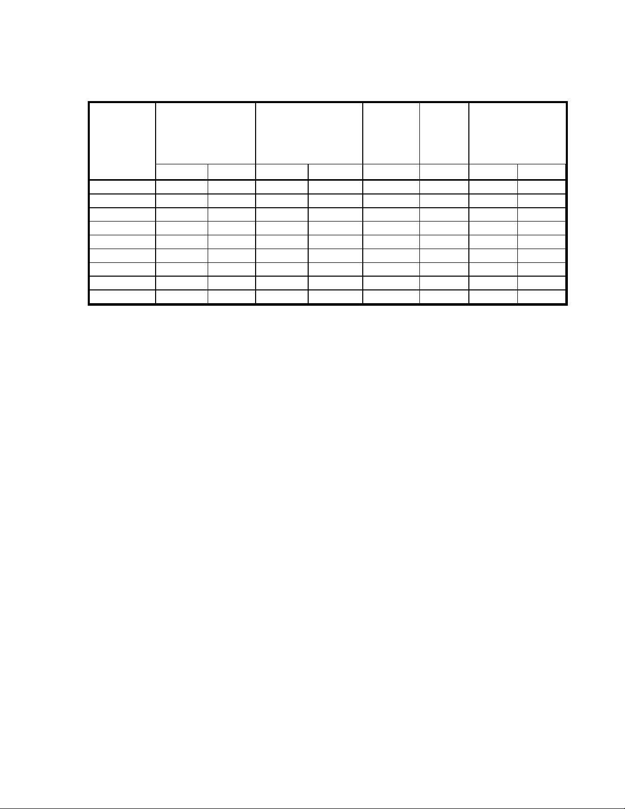
MODEL CONTINUOUS
TORQUE, T
lb. NM rpm lb. in. NM
303-029A 5.5 .62 8600 17 1.92
303-030A 15 1.69 10900 60 6.67
304-111A 12 1.36 7400 50 5.65
304-121A 28 3.16 5650 95 10.73
304-131A 48 5.42 4600 190 21.47
304-141A 73 8.25 2740 380 42.93
304-151A 94 10.62 2675 550 62.15
305-111A 51 5.76 5400 145 16.38
305-121A 74 8.36 4450 220 24.86
c
NO LOAD
SPEED
PEAK TORQUE, T
TABLE 4- 5. STANDARD SERIES 300A MOTOR RATINGS
p
Page 18
SECTION FOUR - COMPONENT DESCRIPTION AND SPECIFICATION 4.17
MODEL TORQUE
CONSTANT, K
lb. in./amp NM/amp
t
Inertia, J
lbin.s2*10
-3
m
kg-m2*10
-4
Mech. Time
Constant,
t
m
msec msec LB kg
Elect
Time
Constant,
t
e
Weight
303-029A 3.53 .40 .16 .18 2.33 0.64 3.0 1.4
303-030A 2.78 .31 .37 .42 1.14 1.24 4.0 1.8
304-111A 4.13 .47 .9 1.0 2.50 1.20 6.4 2.9
304-121A 5.39 .61 1.6 1.8 1.50 1.91 7.5 3.4
304-131A 6.65 .75 2.7 3.1 1.10 2.58 9.7 4.4
304-141A 11.24 1.27 5.0 5.6 1.10 2.70 13.7 6.2
304-151A 11.51 1.30 7.3 8.2 1.00 2.75 17.8 8.1
305-111A 5.61 .63 5.2 5.9 1.70 4.20 15.6 7.1
305-121A 6.82 0.77 7.3 8.2 1.20 5.40 18.2 8.3
TABLE 4-6. STANDARD SERIES 300A MOTOR CHARACTERISTICS
Page 19

4.18 SECTION FOUR - COMPONENT DESCRIPTION AND SPECIFICATION
THIS PAGE INTENTIONALLY BLANK.
 Loading...