

Page 1
Page 2
Page 3

I see my job as being one that
must provide the artist with
the capability of imparting
complexity and dynamics to
his music.” - Dr. Robert Moog
“
3
Page 4

IMPORTANT SAFETY INSTRUCTIONS
WARNING - WHEN USING ELECTRIC PRODUCTS, THESE BASIC PRECAUTIONS SHOULD
ALWAYS BE FOLLOWED.
1. Read all the instructions before using the product.
A. Keep these instructions. B. Heed all warnings. C. Follow all instructions
2. WARNING: Do not use this product near water. To reduce risk of re or electric shock, do not expose
this product to rain or moisture. - For example, but not limited to: near a bathtub, washbowl, kitchen sink, in a wet
basement, or near a swimming pool or the like.
3. This product, in combination with an amplier and headphones or speakers, may be capable of
producing sound levels that could cause permanent hearing loss. Do not operate for a long period
of time at a high volume level or at a level that is uncomfortable.
4. The product should be located so that its location does not interfere with its proper ventilation.
Do not block any ventilation openings with any items including but not limited to newspapers,
table-cloths, curtains, etc. Install in accordance with the instructions in this manual only.
5. The product should be located away from heat sources such as radiators, heat registers, or
other products that produce heat. No naked ame sources (such as candles, lighters, etc.) should be
placed near this product.
6. The product should be connected to a power supply only of the type described in the operating
instructions or as marked on the product.
7. The power-supply cord of the product should be unplugged from the AC mains socket-outlet
when lef t unused for a long period of time or during lightning storms.
8. Care should be taken so that objects do not fall and liquids are not spilled into the enclosure
through openings.
9. Clean only with a dry cloth.
10. The product should be serviced by qualied personnel when:
a. The power supply cord or the plug has been damaged.
b. Objects have fallen, or liquid has been spilled onto the product.
c. The product has been exposed to rain.
d. The product does not appear to operate normally or exhibits a marked change in performance.
e. The product has been dropped or the enclosure damaged.
INSTRUCTIONS PERTAINING TO RISK OF FIRE, ELECTRIC SHOCK, OR INJURY TO PERSONS.
Do not open the chassis. There are no user serviceable parts inside. Refer all servicing to qualied personnel only.
GROUNDING INSTRUCTIONS: This product must be earth-grounded; if it should malfunction or breakdown,
earth-grounding provides a path of least resistance for the electrical current to reduce the risk of electric shock.
This product is equipped with a cord having an equipment grounding connector and a earth-grounding plug (plug
with a third prong). The plug must be plugged into an appropriate socket outlet that is properly installed and
earth-grounded in accordance with all local codes and ordinances.
DANGER: Improper connection of the equipment ’s earth-grounding connector can result in a risk of electric
shock. Check with a qualied electrician or serviceman if you are in doubt as to whether the product is properly
earth-grounded. Do not modify the plug provided with this product – if it will not t in the socket-outlet, have a
proper outlet installed by a qualied electrician.
NOTE: This equipment has been tested and found to comply with the limits for a class B digital device, pursuant to
part 15 of the FCC rules. These limits are designed to provide reasonable protection against harmful interference in a
residential installation. This equipment generates, uses and can radiate radio frequency energy and, if not installed
and used in accordance with the instructions, may cause harmful interference to radio communications. However,
there is no guarantee that interference will not occur in a particular installation. If this equipment does cause
harmful interference to radio or television reception, which can be determined by turning the equipment off and
on, the user is encouraged to try to correct the interference by one or more of the following measures:
—Reorient or relocate the receiving antenna.
—Increase the separation between the equipment and receiver.
—Connect the equipment into an outlet on a circuit different from that to which the receiver is connected.
—Consult the dealer or an experienced radio/TV technician for help.
CAUTION: Please note that any changes or modications made to this product not expressly approved
by Moog Music Inc. could void the user’s authority granted by the FCC to operate the equipment.
Page 5

TABLE OF CONTENTS
7 UNPACKING & INSPECTION
7 SETUP & CONNECTIONS
9 OVERVIEW & FEATURES
9 BASICS OF SOUND
12 BANK & PRESET SELECTION
13 PROGRAMMING SECTION
14 KEYBOARD OCTAVE BUTTONS
15 ARPEGGIATOR SECTION
17 STEP SEQUENCER
18 STEP EDIT MODE
21 GLIDE SECTION
22 MODULATION SECTION
25 OSCILLATORS SECTION
27 MIXER SECTION
28 FILTER SECTION
29 ENVELOPE GENERATORS
34 OUTPUT SECTION
35 MIDI MENU
Page 6

TABLE OF CONTENTS
39 PRESET MENU
43 GLOBAL MENU
50 CONTROLLERS MENU
52 MIDI OPERATIONS
56 NRPN OPERATIONS
60 SERVICE & SUPPORT INFO
61 SPECIFICATIONS
Page 7

UNPACKING AND INSPECTION
Check the contents of the shipping carton
Be careful when unpacking the Subsequent 37 so that nothing is lost or damaged. Moog recommends
saving the carton and all packing materials in case you ever need to ship the instrument for any reason.
The Moog Subsequent 37 ships with the following items:
I. Subsequent 37 analog synthesizer
II. Power cord
III. Owner’s manual
IV. Registration card
What you will need:
I. A stand or table sufcient to support the Subsequent 37
II. Either a 1/4 inch instrument cable and amplied speakers or headphones with a 1/4 inch plug
III. A properly wired AC outlet
SETUP AND CONNECTIONS
Place the Subsequent 37 on a stable surface such as a keyboard stand at a height suitable for
playing comfortably.
External
Audio in
I
O
USB MIDI
5-Pin DIN MIDI
Control Voltage
7
Page 8

POWER
Plug one end of the supplied AC cord into the standard IEC power connector on the Subsequent 37’s
left-side panel. Plug the other end into an AC outlet. Warning: An apparatus with CLASS I construction
(such as this device) shall be connected to a MAINS socket outlet with a protective earthing connection.
The Subsequent 37’s universal power supply will operate with 50/60Hz AC power sources ranging from
100 to 240 VAC / 50-60 Hz using 13W. Flip on the power switch located next to the power connector.
NOTE: It may take as long as 60 seconds for the Subsequent 37 to warm up before oscillator tuning has
stabilized if you’ve left it outside on a cold night. (Although its oscillators are surprisingly stable, the
Subsequent 37 is an analog synthesizer, after all.)
AUDIO OUT
With the MASTER VOLUME turned all the way down, plug one end of a 1/4 inch instrument cable into the
Subsequent 37’s AUDIO OUT jack and the other end into an amplied speaker or mixing console input.
Adjust the level by slowly turning the MASTER VOLUME knob clockwise while playing the keyboard.
If you’ll be using headphones, plug them into the headphones jack (on the front panel’s bottom-right
corner) with HEADPHONE VOLUME turned all the way down. Adjust the level by slowly turning the
HEADPHONE VOLUME knob clockwise while playing the keyboard. Note that MASTER VOLUME
must be turned up as well.
EXTERNAL AUDIO IN
Located just above the AUDIO OUT jack, the jack labeled EXT IN allows the Subsequent 37 to shape and
lter external sounds. This is an unbalanced input that accepts a line-level signal.
NOTE: You must press a key to pass external audio through the Subsequent 37. You also can use a Moog
FS-1 footswitch, or simply press the LATCH ON button in the Amplier Envelope section and make sure that
the Amplier Envelope’s SUSTAIN level is up.
USB
To use the Subsequent 37 with a computer, connect one end of a USB cable to the Subsequent 37’s
USB port and the other end to an available USB port on your computer. The Subsequent 37 supports
MIDI I/O over USB, but not audio data. The Subsequent 37 is class compliant. No drivers are required
for USB MIDI connectivity.
MIDI
Using the Subsequent 37 with an external MIDI device requires one or two MIDI cables. To use the
Subsequent 37 as a MIDI controller, connect one end of a MIDI cable to the Subsequent 37’s MIDI OUT
jack and the other end to another device’s MIDI IN jack.
To control the Subsequent 37 from an external MIDI controller, connect one end of a MIDI cable to the
Subsequent 37’s MIDI IN jack and the other end to an external controller’s MIDI OUT jack. By default,
the Subsequent 37 is set to transmit and receive MIDI data on MIDI Channel 1.
CONTROL VOLTAGE IN
The PITCH CV, FILTER CV, and VOL CV inputs each accepts an expression pedal (such as the Moog EP-
3) or a control voltage signal from 0 to +5 volts. If you connect a TRS expression pedal to VOL CV, you
can use your foot to control the Subsequent 37’s output level. If you connect a TRS expression pedal to
FILTE R CV, you can sweep the lter cutoff in the same manner. The PITCH CV input is calibrated so that
a one-volt change in the control voltage will result in a one-octave change in frequency.
The KB GATE input accepts a +5 volt signal, which causes the Subsequent 37’s envelopes to trigger.
8
Page 9
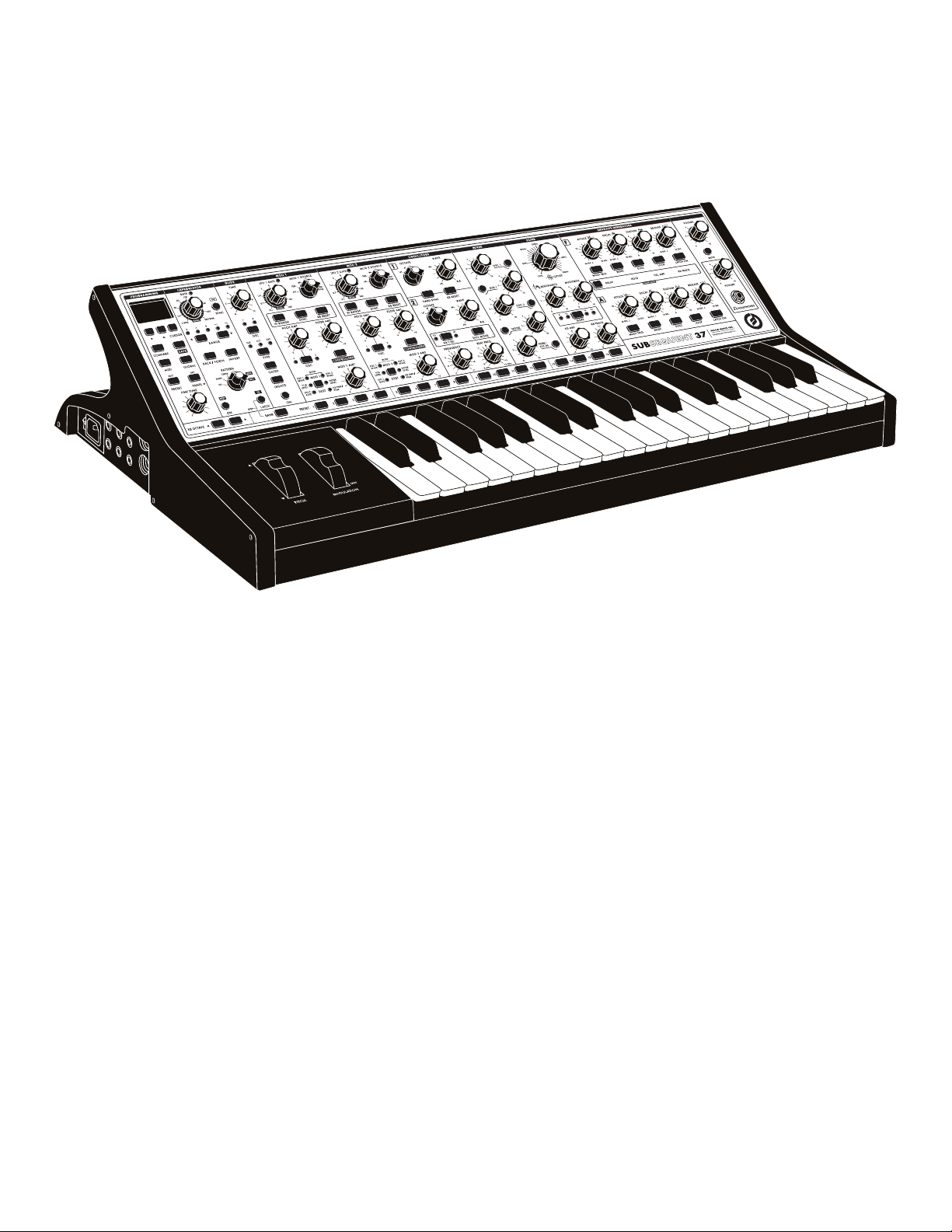
OVERVIEW AND FEATURES
The Subsequent 37 is a 2-note paraphonic analog synthesizer, built in the tradition of classic Moog
synthesizers. It is housed in a rugged black steel chassis with aluminum extrusion, and nished with
classic wood sidepieces. Your new Subsequent 37 starts with a high-quality, 37-note keyboard that has
both velocity sensitivity and aftertouch. This offers a highly expressive and musical playing experience.
All critical performance and sound design features are provided directly on the front panel, which is
equipped with 40 knobs and 74 switches. This makes creating, saving, and retrieving your own sounds
fast and effortless. Each knob and switch on your Subsequent 37 also sends and receives MIDI, making
the Subsequent 37 a completely automatable analog synthesizer and powerful MIDI controller.
Unlike its smaller sibling, the Subsequent 37 has the ability to play more than one note at a time via a
new function called DUO MODE. This allows each of the Subsequent 37’s highly stable oscillators to
play completely independent pitches from one another. Voices are then processed through a single,
classic 20Hz-20kHz Moog Ladder Filter. The Filter section has a dedicated selector switch for lter
slope, and control for MultiDrive. When combined with the new Mixer Feedback function, a vast array
of sound creation possibilities become available.
The Subsequent 37 boasts 2 fully assignable modulation busses, 2 DAHDSR looping envelopes, and a
powerful arpeggiator with a paraphonic 64-note step sequencer. Each of these sections has a
dedicated SYNC switch, which allows you to easily determine which features are synchronized
to MIDI, internal clock, or running free.
With its extensive feature set and one-knob-per-function design, the Subsequent 37 is the ideal
instrument for any synthesist, sound designer, or performing musician.
BASICS OF SOUND
If you’re new to the world of music synthesis, it helps to have at least a rudimentary understanding of
music and acoustics. Even if you know this stuff like the back of your hand, it never hurts to approach it
from a fresh perspective.
Several qualities distinguish one musical sound from another, including pitch, loudness, duration, and
timbre. Being able to manipulate those qualities allows you to turn raw sound into music.
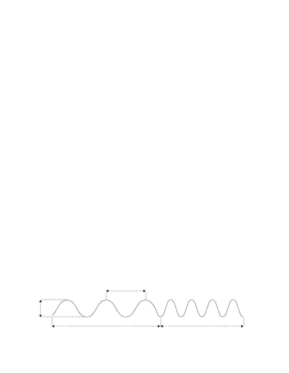
Simply put, sound occurs when a vibrating object causes the air around it to vibrate. That object could
be a guitar string, a loudspeaker, or anything capable of rapid movement. An individual vibration is
called a wave or cycle, and the rate of vibration is called frequency. Frequency determines the sound’s
pitch, and pitch determines how high or how low you perceive the sound on a musical scale. Frequency
is measured in Hertz (abbreviated Hz), which describes the actual number of times that something
vibrates every second. One thousand cycles per second is called a kilohertz (kHz).
wavelength
amplitude
low frequency high frequency
9
Page 10

BASICS OF SOUND (CONTINUED)
Amplitude—the intensity of vibration—determines a sound’s loudness. A high-amplitude sound
is loud, and a low-amplitude sound is soft. A vibrating source’s loudness depends on the amount
of air it displaces, and that depends on how hard it vibrates.
It’s difcult for anyone to identify a musical instrument simply by the pitch or loudness of the sounds
it makes. Every musical sound also has a characteristic tone color or timbre (pronounced tam’–br, as
in tamborine, not tim’–br, as in a tree falling). Differences in timbre make it possible to distinguish one
instrument from another.
If you analyze a single cycle of a musical sound, you can perceive it as a complex combination of
simple sine waves, each wave different in frequency and amplitude. When their frequencies are wholenumber multiples of each other (and in musical sounds, they usually are), those simple waves are called
harmonics. A sound’s timbre depends on its harmonic content. The rst harmonic—the one with the
lowest frequency and usually the greatest amplitude—determines its pitch. Higher harmonics are often
called overtones. Normally, the higher the overtone’s frequency, then the weaker its amplitude.
When those harmonics are combined in a musical sound, a single cycle of that sound has a specic
shape, which synthesists call a waveform. Just as the frequencies and relative amplitudes of the
sound’s harmonics determine its waveform, the waveform determines the sound’s timbre.
Instead of producing sounds acoustically the way vibrating objects do, synthesizers generate
electrical signals that are amplied and converted to sound. Just as sound has frequency and
amplitude, so does the kind of alternating current produced by a synthesizer. An analog
synthesizer’s primary sound source is called an oscillator.
The oscillator’s waveform, of course, determines the sound’s harmonic content. Some waveforms
are rich in harmonics, while others have relatively few. Depending on the waveform, some overtones
may be absent altogether. Waveforms with lots of overtones, such as sawtooth and square waves, are
harmonically the most complex. Waveforms with fewer overtones, such as triangle and narrow pulse
waves, are harmonically less complex.
Rather than building up waveforms one harmonic at a time, the way a Hammond organ does, analog
synthesizers like the Subsequent 37 provide the means to shape and lter complex, harmonically
rich waveforms to selectively remove, reduce, or emphasize specic harmonics—a technique called
subtractive synthesis.
KB: Keyboard (Pitch Voltage)
VCO: Voltage Controlled Oscillator
VCF: Voltage Controlled Filter
EG: Envelope Generator
LFO: Low Frequency Oscillator
VCA: Voltage Controlled Amplifier
The Subractive Synthesis Model
10
Page 11

The oscillators, lter, modulators, and other parts are connected in the most useful ways for
producing and modifying electronic signals that result in sounds. Unlike on a modular synthesizer,
many connections between the Subsequent 37’s various parts are hardwired, meaning that it is not
possible to change the routing of the pathways that connect them.
The electrical signals within a synthesizer are either audio signals or control signals, depending on
the pathway they follow. Typically, an audio signal begins with an oscillator and passes through the
lter on its way to the audio output. Control signals are used to change things, like the pitch, timbre,
waveshape, or loudness of an audio signal.
Any time a signal controls something, no matter whether it’s controlling an audio signal or another
control signal, we say that it modulates it. In synth-speak, you could say that a steering wheel
modulates a car’s direction and the accelerator pedal modulates its speed. When you play the
Subsequent 37’s keyboard, the key you press modulates the instrument’s pitch. You can modulate lter
cutoff by turning a knob manually, or you can apply a control signal from a low-frequency oscillator or
envelope to modulate it electronically. It’s worth noting that a control destination can be modulated by
more than one control source.
The diagram below illustrates how the Subsequent 37 generates sound. It shows the ow of audio
signals, represented by solid lines, and control signals, represented by dotted lines.
VCO 1
SUB LVL
VCO 1
LVL
VCO 1 MOD
& CNTRL
PITCH 1 CV
& MOD
NOTE
SYNC
PITCH 2 CV
& MOD
OSC 1-2
SYNC
VCO 1
CORE
VCO 2
CORE
VCO 1
SUB
VCO 1
WAVE
VCO 2
WAVE
SUB 1
VCO 1
MIXER
VCO 2
FILT SLOPE
SELECT
LADDER
FILTER
MULTIDRIVE
MULTI-
DRIVE
VCA
H. PHONE
AUDIO
AUDIO
OUT
VCO 2 MOD
& CNTRL
VCO 2
LVL
NOISE
LVL
FILTER EG
CV & MOD
RESO-
NANCE
VCA EG
& CV
FDBK/EXT
AUDIO LVL
NOISE
CORE
NOISE
EXT. AUDIO
FEEDBACK
EXT
AUD
You can control the Subsequent 37 using control voltages and MIDI commands. When the Subsequent
37 receives either a control signal from the onboard keyboard or a Note On command from an external
MIDI source, it responds by sending a gate signal to trigger the envelopes and a control voltage (CV)
to control oscillator pitch. The envelopes respond by sending control signals to the amplier and lter.
Every knob and button on the Subsequent 37 transmits MIDI data (when in NRPN Mode). This
functionality is useful for recording your knob turns and button presses into a computer-based DAW,
as well as for controlling external devices using the Subsequent 37’s front-panel controls. All the
settings that make up a patch are called its parameters, which is simply another name for settings.
11
Page 12

BANK & PRESET SELECTION
The Subsequent 37 ships with 256 user-editable preset locations, which are arranged in 16 banks of
16 patches per bank. The following section will show you how recall existing patches, and also how to
edit and save your own patches. (The word patch is a holdover from modular synthesis, which requires
patch cords to connect the various modules.)
SELECT A BANK & PRESET (USING BANK/PRESET BUTTONS)
1. Press the BANK button, which will illuminate.
2. Press one of the PRESET buttons labeled 1 - 16. Your bank is now selected. (The BANK and PRESET
buttons will darken until a new preset is selected).
3. Now select a preset from within your selected bank by pressing the desired PRESET button labeled
1 - 16. The corresponding PRESET button will now remain illuminated.
NOTE: If you press a PRESET 1 - 16 button without rst pressing BANK, you will simply choose presets
from within the current bank.
Take your time, listen to all the presets, and turn some knobs to get a feel for how you can use them
to alter sounds. To return to the original stored preset, just select it again by pressing the currently
illuminated PRESET number button.
NOTE: If your display screen is not in PRESET mode and you wish to see which bank you are currently
in, press the BANK button and one of the buttons from 1 – 16 will illuminate. Press the BANK button
again to return to PRESET selection mode.
SELECT A BANK & PRESET (USING CURSOR AND BUTTONS)
Make sure that the PRESET button in the PROGRAMMING section is lit. The display screen will show
the title of the preset (one or two lines) followed by its bank (BNK) and preset (PRESET) numbers. The
last line shows the category (CAT) for that preset.
You can scroll through individual presets by using the CURSOR button to highlight the PRESET
number eld. Now use the buttons to scroll through all 256 presets. If you press and hold
either button it will scroll rapidly.
As you pass the 16th preset in a bank, the Subsequent 37 will jump to preset 1 in the next bank.
BROWSING ALL PRESETS IN A SPECIFIC CATEGORY
1. Press the CURSOR until you have highlighted the category type (MISC, LEAD, BASS, BRASS, etc.).
2. Now use the buttons to scroll through available category types.
3. Once you have made your selection press the CURSOR button until you have highlighted CAT.
4. The buttons will now allow you to scroll through every patch in your selected category.
NOTE: Category types can be assigned when you are in the SAVE mode.
SAVING AND NAMING PRESETS
Saving presets is a simple maneuver. Just remember that whenever you save a preset to a particular
location, the preset previously stored in that location will be deleted.
12
Page 13
TO SAVE A PRESET:
1. Press the SAV E button.
2. You will be given an opportunity to name your preset. Use the buttons to select a character,
and use the FINE TUNE knob to scroll through the available characters. Now use the buttons to
select CAT (Category), and the FINE TUNE knob to assign your preset to a sound category. Press SAV E
to accept. (You can also press CURSOR and use the buttons to edit an individual character).
3. Using the BANK/PRESET buttons on the bottom of the front panel, select a save location for your
preset. (If you are already in the bank you want, you can simply choose from PRESET 1-16).
4. Press and hold SAVE for one second to conrm and complete the save process. To cancel saving,
simply press the PRESET button.
NOTE: When you rst press the SAVE button, the current positions of all sound controls are frozen so
that they can be saved with the preset.
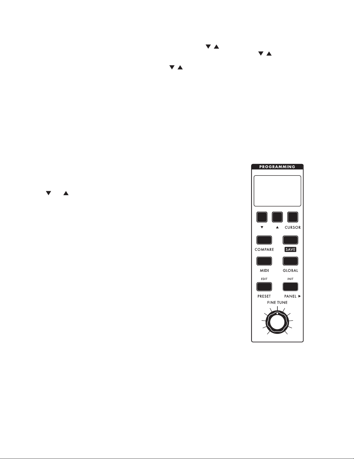
PROGRAMMING SECTION
The Subsequent 37 has a wealth of user-selectable features and functions not
found on its panel. The PROGRAMMING section allows you to easily access
and update any of these things expediently.
Dec , Inc , and CURSOR buttons: These buttons are used for selecting
presets, menu navigation, and editing parameters shown on the Subsequent
37’s LCD display panel.
COMPARE
This button allows you to load an existing preset without discarding any
changes you have made to a current sound. To alternate between a stored
preset and a currently modied sound simply press the COMPARE button.
When the COMPARE button is illuminated, you are listening to a stored preset
and no changes can be made to the sound. When in this mode you can,
however, audition different presets without discarding your currently modied
sound. When the COMPARE button is dark, you have exited COMPARE mode
and are listening to your currently edited sound.
NOTE: You can also press PRESET to exit compare mode.
SAVE
This button is used to initiate the saving of a preset.
MIDI / GLOBAL
These buttons allow you to access and edit system settings for your
Subsequent 37 including MIDI channel selection, pot modes, and keyboard note priority. This is also
where you nd useful operations like note calibration and exporting presets. To learn more about MIDI
and GLOBAL settings, go to page 35 (MIDI) and page 43 (GLOBAL).
13
Page 14
PROGRAMMING SECTION (CONTINUED)
PRESET / PANEL
These buttons select the performance mode of your Subsequent 37. In PRESET mode, the sound
you hear reects the position that the panel knobs and buttons were in when the preset was saved,
regardless of their current position. In PANE L mode, the sound you hear reects the current position
of the front-panel knobs and buttons. Parameters in this mode (other than the knobs) are saved in a
special buffer, so you can pre-set the panel to retain any non-knob settings you choose. Any sequence
data you have created before exiting the PAN EL mode will also be stored to this buffer. To load the
PANEL settings without loading its sequence, hold BANK while pressing PANE L to enter panel mode.
PRESET EDIT
Press and hold the PRESET / EDIT button to enter the PRESET EDIT MENU. This is where additional
preset parameters that would not t on the front panel are located. To learn more about the PRESET
EDIT MENU, go to page 39.
INITIALIZE PANEL
Press and hold the PANEL / INIT button to initialize the Subsequent 37 panel settings to a default
state. This is a great place to start when creating new sounds from scratch.
FINE TUNE
Use this knob to adjust the frequency of both oscillators as much as one semitone up or down from its
center position. Fine-tuning is useful for putting the Subsequent 37 in tune with any other instruments
that deviate slightly from standard pitch.
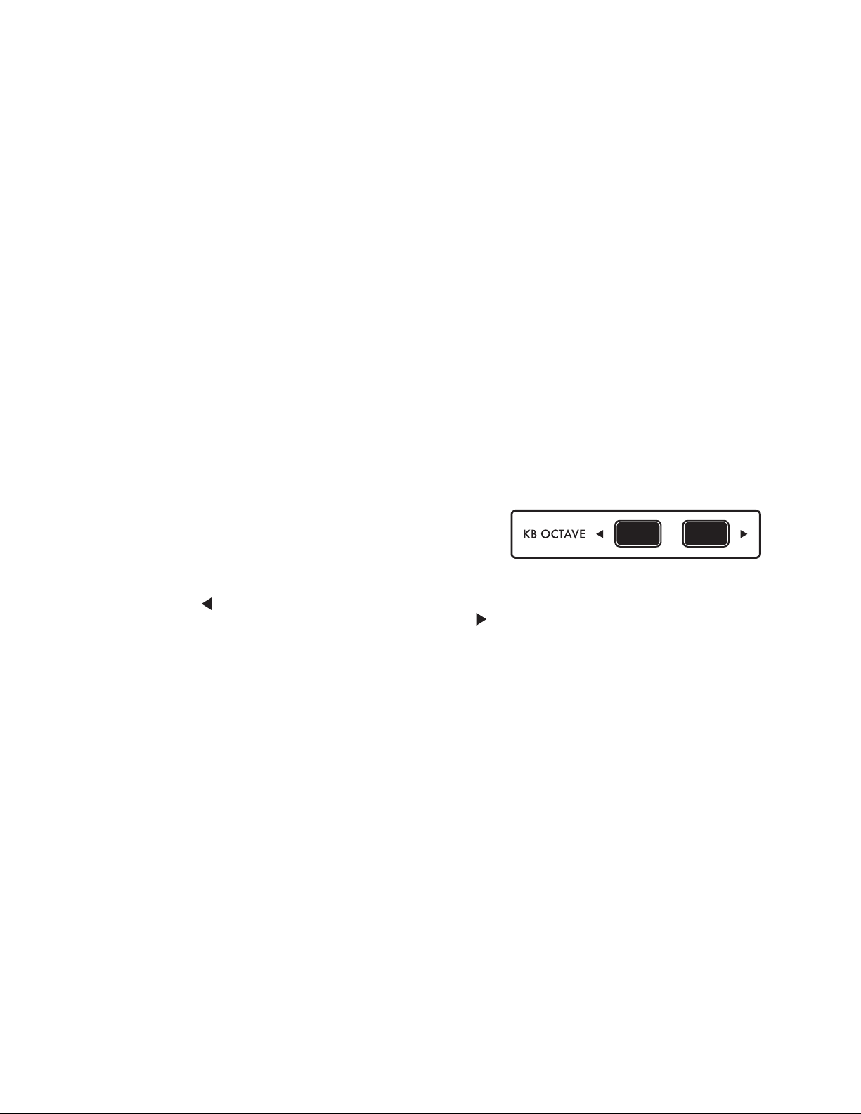
KEYBOARD OCTAVE BUTTONS
Use the K B OC TAV E buttons to extend the Subsequent
37’s keyboard from its normal three-octave range to a full
seven octaves.
Pressing the button once transposes the Subsequent 37’s pitch down an octave. Pressing it again
transposes it down another octave. Likewise, pressing the button transposes the pitch up an octave,
and pressing it again transposes it up another octave. When neither button is illuminated the Subsequent
37’s keyboard is playing in its standard octave. When a KB O C TAV E button is dimly lit, the keyboard is
transposed a single octave. When a KB OC TAV E button is brightly lit, the keyboard is transposed two
octaves.
NOTE: Since this is an analog synthesizer based on 1 volt-per-octave scaling, the extreme high and low
ranges of the keyboard may play notes that are not perfectly in tune.
The KB OC TAV E buttons also transpose the MIDI Note Numbers that the Subsequent 37 transmits by
corresponding amounts.
DEFAULT KB OCTAVE
Briey pressing both K B OCTAVE buttons together will reset the Subsequent 37 to its standard octave
regardless of current octave selection.
QUICK KEYBOARD TRANSPOSE
While holding both the K B OCTAVE UP and DOWN at the same time, play any single note in the lower
two octaves of keys to transpose the entire Subsequent 37 keyboard from -12 half-steps to +12 halfsteps. Pressing Middle C will set the transposition to +0 (default). Keys to the left of Middle C will
transpose downward, and keys above Middle C will transpose upwards. The KB TRNSPOSE value will
be reected in the PRESET EDIT 1.5 parameter as well. This is stored as part of the preset.
MIDI PANIC
Holding both KB O CTAVE buttons at the same time for about one second will send a MIDI Panic (All
Notes and Controllers Off) message.
14
Page 15

ARPEGGIATOR SECTION
With the Arpeggiator ON button lit, any note or group of notes you
play will be sequenced according to the settings in the Arpeggiator
section and menu. You can also record and playback a 1 to 64 note step
sequence, which can be stored with each preset.
LATCH
When ON, the Arpeggiator will keep looping in its current state without
the need to hold a physical note. A new note or group of notes will initiate
a new note sequence based on the Arpeggiator Menu settings. If notes
are played and held while L ATCH is ON, playing additional notes will add
to the current list of notes to be arpeggiated. If all notes are released, the
rst new note played will initiate a new note sequence.
RATE
This knob sets the rate of the arpeggiator from 2 BPM (beats-per-minute)
to 280 BPM. When the SYNC button is illuminated the R AT E knob is
used to select clock divisions of the Subsequent 37’s internal clock or an
external MIDI clock. For more information on MIDI clock divisions, go to
page 52.
SYNC
When ON this button synchronizes the arpeggiator to external MIDI
clock messages. MIDI clock messages are 24 ppq (pulses-per-quarternote) messages that can be sent via MIDI computer sequencers, drum
machines, etc... To enable the sending of these messages, consult the user manual for your external
MIDI device. When the arpeggiator is synchronized to a MIDI clock tempo, the arpeggiator can be set
to time divisions of this tempo using the arpeggiator’s RATE knob. (Time divisions range from 4 whole
notes up to a 64th note triplet).
WARNING: When SYNC is ON, and you are not in TAP TEMPO mode, the arp/sequencer will not play
unless MIDI clock is received.
[TAP]
The SYNC button can also be used to set the arpeggiator’s rate to a desired tempo. To initiate Tap
Tempo of the arpeggiator, press and hold the SYNC button for 1 second. You can now tap the SYNC
button switch at the tempo you want (1/4 notes). On the third tap, the Subsequent 37’s internal clock
will change rates to match the timing of the switch presses. If you continue to tap the SYNC switch,
the internal clock will be set by a running average of the time between switch presses. To start over,
wait ve seconds and then tap the SYNC switch three times to set a new tempo. To exit the Tap Tempo
mode press and hold the SYNC button for 1 second.
RANGE
Use the RANGE buttons to choose how many octaves the arpeggiator will play above or below the
actual notes pressed. The LEDs will indicate -2 octaves, -1 octave, 0 octaves, +1 octave, or +2 octaves.
If you press either RANGE button more than two times you will light up both the 0 and the -2 or +2
LEDs. In this mode the arpeggiator will play all the notes in the original octave, the 2nd octave, the 3rd
octave, and then back to the 2nd octave before returning to the original octave.
15
Page 16

ARPEGGIATOR SECTION (CONTINUED)
BACK / FORTH
When the BACK / FORTH button is illuminated the arpeggiator will play the UP or DWN patterns in a
bi-directional fashion, making UP play up then down, and making DWN play down then up.
For example, if you choose the UP pattern without the BACK / FORTH button and hold C-E-G, you’ll
get C-E-G-C-E-G etc. But, if the BACK / FORTH button is lit you’ll get C-E-G-E-C. If the PATTERN
switch is set to ORDR the arpeggiator will play notes in order and then in reverse order. The
BACK /FORTH setting has no effect on the RND pattern.
NOTE: There is a parameter in the PRESET EDIT MENU (Page 39) called END NOTES that determines if
the beginning and ending notes of the arpeggiation are played once (ONCE) or twice (TWICE) when they
change direction. For example, if you’re arpeggiating C-E-G using the UP Pattern with the BACK / FORTH
button lit, you get C-E-G-E-C etc. if you choose ONCE. If you choose TWICE you’ll get C-E-G-G-E-C-C etc.
INVERT
When the INVERT button is lit the arpeggiator will play each note in two or three successive octaves
before moving to the next note. If the RANGE parameter is set to +1 with INVERT lit, and you hold
C-E-G, you will get C, C up one octave, E, E up one octave, G, and G up one octave. Because this
function is octave based, the INVERT button will have no effect if the arpeggiation RANGE is set to 0.
PAT TE R N
Use the PAT T E R N knob to choose the manner in which notes are played back by the Subsequent 37
arpeggiator. When UP is selected, held notes will play back in order of pitch from lowest to highest.
When DWN is selected, held notes will play back in order of pitch from highest to lowest. When ORDR
is selected, held notes will play back in the order they were held. When RND is selected, held notes
will play back in a completely random order.
You can also use the PATTE R N knob to select the Subsequent 37’s built-in Step Sequencer. If the
arpeggiator is not running, setting the PATTERN knob to REC and playing a new note will clear any
existing sequencer data. This allows you to record a new Step Sequence containing up to 64 notes.
If you turned the PATTERN knob to REC by mistake, that’s okay. Simply turn it back to the desired
position and your original sequence will still be there. Learn more about the step sequencer on page 17.
ON / REST
The ON button is used to engage or disengage the arpeggiator, allowing you to pre-set the arpeggiator and
then turn it on as needed. When in Step Sequence Record mode, the ON button becomes RE ST. Pressing the
REST button will advance to the sequencer to the next step and add a silent REST to your Sequence.
LATCH / TIE
When ON, the L AT CH button allows the Subsequent 37 to continue playing an arpeggio or sequence
even after all the keys have been released. When in Step Sequence Record mode, pressing the
LATC H button becomes TIE, which will connect your previous note to the next note you play without
advancing to the next step in a sequence.
16
Page 17

STEP SEQUENCER BASICS
With the arpeggiator disengaged (ON button is darkened), turn the PATTE R N knob to REC. The next
key you press will erase any existing step sequence data and enter a note for step 1. The LCD display
will also show REC 01 / 01, indicating that you have recorded step 1 of a (so far) 1-step sequence. Each
successive key press (or REST) will advance you to the next step number for up to 64 steps.
After entering a note, pressing the TIE button will tie (connect) your previous note to the next note
you play. If you play a different note from the previous one using a tie, you will hear the new pitch
without triggering the envelopes. If you play the same note as the previous one using a tie, you will
effectively double the length of the note.
NOTE: With Glide set to ON and the LEGATO button illuminated, the glide effect will only occur between
the tied notes.
You can also create a tie between two different notes by pressing a second note before releasing the
previous note. This shortcut will not work if you are in DUO MODE.
After recording your step sequence, turn the PAT TERN knob to SEQ. Then press the Arpeggiator ON
button. Now you can play back your step sequence in any transposition by pressing a key. The key you
press will be the starting note of your step sequence.
NOTE: In the GLOBAL MENU, if you set REF NOTE to be MID C, then pressing Middle C will play back
your step sequence exactly as you recorded it. Playing C# will play back your sequence a half step up.
Playing the Bb below Middle C will play your sequence a whole step lower.
STEP SEQUENCING IN DUO MODE
With DUO MODE engaged, you can choose (per step) whether
to enter one or two notes together. When two notes are played
simultaneously, the sequencer captures two separate pitches.
The KB CONTROL settings determine which oscillator follows
which note.
When you play the sequence back you will hear both notes on steps that were recorded with two
notes, and both oscillators playing together on steps in which only one note was pressed.
During playback, if you hold down two notes, all of the recorded duo notes will play back normally. Any
single recorded notes, however, will follow your two keys as dictated by KB CTRL settings. This allows you
to play real-time pitches along with a step sequence any time there is only one note recorded in a step.
If your step sequence consists only of single notes you can play along with your own melody. If your step
sequence consists only of duo notes, then playing a second key during playback will have no effect.
NOTE: A step sequence can be stored with each preset. This means you can store multiple versions of a
single preset, allowing you to switch between different sequences while continuing with the same sound.
17
Page 18
STEP EDIT MODE
Using the Step Edit mode you can edit everything about every step of a sequence (in real or
non-real time). For each step, this includes the note number of either one or two notes, the velocity
of the step, whether there’s a rest or a tie, and the per-step SEQ MOD value. You can also decide
(non-destructively) which step is the rst step, and which step is the last step of the sequence. You
can ROTATE (shift) the pattern relative to the downbeat, SKIP any desired steps, and add a rapid
note subdivision to any step via R ATCH E T.
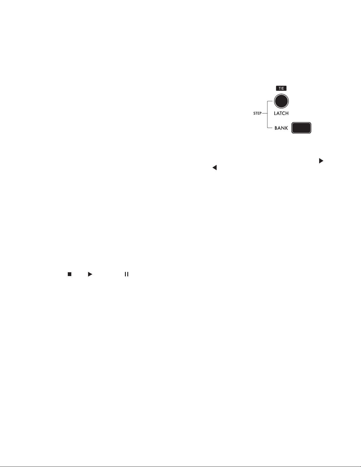
ENTER / EXIT STEP EDIT MODE
Set the ARPEG G IATOR PAT T E R N knob to either SEQ or REC. Then hold
the BANK button and press the L AT CH button to enter or exit STEP EDIT
MODE. You can also exit Step Edit mode by moving the PAT TERN
knob away from REC and SEQ (UP, DWN, ORDER, or RND).
In STEP EDIT MODE, the PRESET buttons (1 - 16) are used to show and edit the pattern’s step data.
Steps 1 through 64 are displayed as four pages, with each page representing 16 of the steps at a time. To
change which sequence page is currently displayed, hold the BANK button and press the KB O CTAVE
button to increment the sequence page, and the KB OCTAVE button to decrement the sequence
page. The page number is indicated (P1 - P4) in the bottom right corner of the LCD display.
SEQ PG CHASE (Located in GLOBAL MENU 2)
Toggles the page-chase behavior for the sequence page display. When ON (default) the step buttons
(PRESET 1 - 16) will rst show steps 1 - 16, and then steps 17 - 32, then 33 - 48, etc. When SEQ PG
CHASE is OFF, the step buttons will remain on the sequence page selected by the user.
VISUAL INDICATIONS OF STEP EDIT MODE
When the BANK button is pulsating slowly, it indicates that you are in Step Edit mode. These pulses
also indicate that no specic step has been chosen for editing.
The bottom line of the LCD gives four pieces of information (from left to right):
• Stop , Play , and Pause show the sequence’s play status.
• EDIT indicates that you are in Step Edit mode.
• CURRENT STEP (1/XX) shows which step of a sequence you are on.
• LAST STEP (X/64) shows the last step number; after playing the last step, the sequence will
repeat from the beginning.
The PRESET buttons are lit dimly for active steps, dark for rests, and dark for all steps after the last step.
Ex. For an 8-step sequence with a rest on step 5, steps 1 - 4 and 6 - 8 would be dimly lit. Steps 5 and
steps 9 - 64 would be dark.
During playback, the current step is lit at full brightness. This brightness will chase across the
PRESET 1 - 16 buttons in sync with the sequence playback.
EDITING A STEP
To select a specic step for editing, hold the BANK button and press a step button [PRESET 1 - 16].
The BANK button will go dark, and the selected step button now pulsates. Now that you’ve selected a
step for editing, you can choose any other step to edit by simply pressing that desired step’s button.
To exit this mode (and deselect any step for individual editing), simply press the BANK button. The
BANK button will resume pulsing, and the previously selected step button will return to its specied
state (active, rest, currently playing, etc.) as described above.
18
Page 19

EDITING A STEP (CONTINUED)
While a step is selected for editing:
REST [ON] and TIE [LATCH] buttons show and toggle the rest or tie state for the selected step.
Note entry (via keyboard or MIDI) edits the pitch of the selected step as follows:
• Any non-legato note sets Pitch 1 and clears the Rest, Tie, and Ratchet data.
• Any legato note sets Pitch 2.
NOTE: If the DUO MODE button is held when a note is entered, then the note entry sets Pitch 2 without
modifying Pitch 1.
If, during step editing, the PATTE R N knob is set to REC (instead of SEQ), then the selected step also
determines the step from which step recording will commence. After the release of all notes, the step
is deselected and the sequence is advanced to the next step. The Subsequent 37 is now ready to
record all further notes in the normal fashion for step recording.
TIE GROUPS OF STEPS
Hold a step button and press another step button to Tie these steps and any steps in-between
together. If the last step of this new Tie group was already set with a Tie, then the original Tie will be
cleared. Press the same two step buttons together a second time to un-Tie all the notes in the group.
TOGGLE STEP REST STATE
Press and release a single step button to toggle Rest on/off.
SET FIRST STEP/LAST STEP
To set a certain step as the sequence’s rst step, press and hold the desired step button and press the
KB O C TAVE button. To set a certain step as the sequence’s last step, press and hold the desired
step button, and press the KB OCTAVE button.
NOTE: You can also CURSOR to the last step number displayed on the LCD and dictate a new last step
using the buttons.
ROTAT E PAT T E R N
You can shift the entire sequence’s step data “left” or “right” (relative to the downbeat) by holding
BANK and pressing the ARPEGGIATOR RANGE [<] and [>] buttons.
BANK + RANGE [<] shifts the pattern to the left by one step per press.
BANK + RANGE [>] shifts the pattern to the right by one step per press.
NOTE: When rotating patterns, there are two Sequencer Transpose modes found in the GLOBAL MENU
2.2/SEQ OPTIONS sub menu. The options are FIRST (First Note - default) or MID C (Middle C plays
recorded pitch). If transposition is based on “First Note” and you rotate a pattern, this will affect how
the sequence is transposed when you play a new key on the keyboard. The new rst note becomes the
new root note for transposing from the keyboard. In MID C mode, playing Middle C on the keyboard
(note 48) will cause the sequence to play in its recorded key, regardless of which pitch has been rotated
to be the rst in the sequence. If you plan on Rotating your patterns while playing live, it’s best that you
choose MID C in the GLOBAL MENU 2.2/SEQ OPTIONS sub menu.
SKIP
To toggle SKIP on/off for a step, hold the desired step’s button and then press the ARP ON [REST]
button. Skip allows you to temporarily remove a step from a sequence. The note prior to the Skipped
note will proceed directly to the note after the Skipped note.
19
Page 20

STEP EDIT MODE (CONTINUED)
RATCHET
To toggle R ATCHET on/off for a certain step, hold a step button and then press the ARP LATCH [TIE]
button. Ratchet causes a step to repeat multiple times within a single step-duration. You can set the
ratchet multiple from 1x (no repeats) to 8x. The RATCHET CNT multiple can be edited in the PRESET
EDIT / SEQUENCER sub menu.
NOTE: RTCHT CT is also a MOD destination.
There is also a panel button-combo to change RATCHET CNT. Hold the BANK button and press ARP
BACK/FORTH to decrease, or hold the BANK button and press the ARP INVERT button to increase
the ratchet multiple.
NOTE: The RATCHET CNT multiplier is universal for the entire sequence. You cannot have different
Ratchet Counts per step, however, you can assign the SEQ MOD value (see below) directly to the
RTCHT CT parameter so that every step can, effectively, have its own Ratchet Count.
TRY THIS: Go to GLOBAL MENU > CV MAPPING and map VOLUME to RTCHT CT. Now, plug a Foot
Controller with a TRS plug into the VOL CV jack on the left side of the Subsequent 37. Toggle Ratchet
On for some (or all) of your steps. Now you can sweep the Ratchet count on those Ratcheted steps
from 1x to 8x, in real time.
SEQ MOD VALUES W/ MOD WHEEL
Whether you are recording a sequence in step time, or editing a step, the current position of the MOD
WHEEL (SEQ MOD value) is recorded for each step. These per-step SEQ MOD values can be used in two
ways: directly via the MOD DST parameter, and as a MOD 1 or MOD 2 SOURCE (the source is called SEQ MOD).
The SEQ MOD values can be assigned to a specic parameter via the PRESET EDIT > SEQUENCER >
MOD DST parameter. The amount of modulation to the specied MOD DST can be scaled using the
SEQ MOD AMT parameter directly below the MOD DST parameter. The SEQ MOD AMT parameter
values go from OFF (0%) to 100%. The total amount of modulation can also be scaled by the MOD
WHEEL during sequence playback by setting the MODWHL CTRL parameter to ON.
It is crucial to understand that the SEQ MOD values are bi-polar, meaning that when the MOD WHEEL
is all the way down, it records a value of -100%. When the MOD WHEEL is all the way up, it records a
value of +100%. When the MOD WHEEL is centered, it records a SEQ MOD value of 0% (and has no
effect on the destination).
It is equally important to understand that the bi-polar SEQ MOD value is added to the current setting of
whatever parameter it is modulating. For example, if the MOD DST is OSC2 LEV, and the OSC 2 value in
the MIXER section is set to 5, then the bi-polar SEQ MOD values could move the OSC 2 level to either
silence or to full volume. But, if the OSC 2 value in the MIXER was set to 0, then the bi-polar SEQ MOD
values would have no effect on the OSC 2 level until those values were greater than 0. This is a complex
tool, and should be explored in simple settings to fully appreciate its function and applications.
Rests, Ties, Seq Start, Seq End, Ratcheted and Skipped steps, as well as the SEQ MOD values, are all
saved with each sequence.
SEQUENCE QUICK-ERASE
Hold BANK while turning the PATTERN knob to the REC position. If the sequence is stopped it will be
completely erased. If the sequence is running, it will continue to run and the sequence length (number
of steps) will remain the same, but all of the steps will be blank (silent).
20
Page 21

GLIDE SECTION
Glide, also called portamento or glissando, is used to cause smooth changes in
pitch between notes.
TIME
Use this knob to specify how much time it takes to transition from one pitch to
the next when you play the keyboard.
OSC
The OSC button assigns the glide effect to Oscillator 1, Oscillator 2, or Both
Oscillators at the same time. The LEDs marked 1 and 2 will indicate which
oscillators have glide assigned to them.
TYPE
Use the TYPE button to choose from three different types of glide: linear
constant rate (LCR), linear constant time (LCT), and exponential (EXP).
LCR: The glide rate will depend on the size of the interval between notes. The
larger the interval, the longer the glide time will be. This is the most commonly
used type of glide.
LC T: The glide time will stay the same between notes, regardless of the interval.
EXP: The glide rate follows an exponential curve that begins with a fast rate and
slows as it approaches the target note.
GATE D
Activating GAT ED glide causes the gradual gliding between notes to be started and stopped by the
keyboard gate. When the GATE D button is illuminated, the pitch CV only glides while a key is held.
When the G ATED button is off, the pitch CV will continue gliding to the target pitch at the current
glide rate, regardless of whether or not a key is held on the Subsequent 37. The different behaviors are
more distinct at longer glide times.
LEGATO GLIDE
Although glide is normally applied to every note you play when engaged, the LEGATO GLIDE function
causes glide to occur only when you press a key while still holding a previous key. LEGAT O and ON
must both be illuminated for LEGATO GLIDE to take effect.
GLIDE ON
Pressing the ON button allows you to engage or disengage the glide effect without having to change
your GLIDE TIME setting. This button must be illuminated for the glide effect to occur.
21
Page 22

MODULATION
Controlling modulation (abbreviated as MOD) is an important
aspect of programming and playing synthesizers. When
you modulate a synthesizer’s audio signal, you are changing
something about the way it sounds. When you modulate a
control signal, you are changing something about its effect on
whatever it’s controlling. Synthesizers route their control signals
from modulation sources to modulation destinations. On the
Subsequent 37, a changing control signal can modulate pitch, lter
cutoff, waveform shape, VCA level, LFO rate, noise level, EG time,
and a variety of additional destinations available via the PRESET
EDIT MENU.
The Subsequent 37 has two modulation busses labeled MOD 1 and
MOD 2. They are nearly identical except that, by default, the overall
depth of MOD 1 is determined by the MODULATION wheel. You can
access and edit this, and other extended modulation parameters by
pressing the CONTROLLERS button.
Low-frequency oscillators generate repeating waveforms in the
sub-audio frequency range. The Subsequent 37’s LFOs also have a
HI RANGE button, which allows the LFOs to generate frequencies
well into the audio range as well. At sub-audio rates, the LFOs are
useful for generating repeating effects. At audio rates, the LFOs add
harmonic complexity to their destinations.
When an LFO modulates an oscillator’s frequency, the oscillator’s
pitch follows the shape of the modulating waveform. If the
LFO’s output is a triangle wave, the pitch rises and falls at a regular rate. At the proper rate and
depth, this type of modulation is called vibrato. Many performers rely on vibrato to add expression
to their performances. A violinist or guitarist employs vibrato with a shaking motion of the hand as it
applies pressure to the string. A singer subtly uctuates their vocal pitch. A synthesist uses an LFO
to modulate an oscillator’s frequency. The LFO R ATE knob controls the rate of modulation, and the
MODULATION wheel controls its depth.
MODULATION CONTROLS
LFO RATE
By default, the LFO RATE knob varies the low-frequency oscillator’s modulation rate from 0.1Hz (one cycle
every 10 seconds) to 100Hz (100 cycles per second). This can be multiplied 10x by using the HI RANGE button.
SOURCE
Use this knob to specify whether the modulation source is one of 5 LFO waveforms, the lter envelope,
or a programmed source. At its most counterclockwise position, the LFO generates a triangle wave,
which is particularly useful for vibrato. Turning the knob clockwise, the next position generates a
square wave, which is useful for performing trills and tremolo effects. The next two positions generate
sawtooth and ramp (reverse sawtooth) waves. Applied to pitch, sawtooth-wave modulation is useful
for simulating alarms, ray guns, and other ascending and descending effects.The fth position uses
sample-and-hold as a modulation source. Think of sample-and-hold as a source of random control
signals. (Think 1970’s Hollywood sound effects of a computer “thinking”.)
When SOURCE is set to F. EG/PGM, the LFO is bypassed and by default, the lter’s envelope settings
are used as a source of modulation. A variety of additional modulation sources are also available to
you by pressing the CONTROLLERS button. To learn more about the MOD CONTROLLERS menu, go
to page 50.
22
Page 23

MODULATION CONTROLS (CONTINUED)
HI RANGE
When engaged, the rate of the LFO is increased by 10x. In this mode, the LFO range is from 1Hz (one
cycle per second) through 1,000Hz (1,000 cycles per second).
NOTE: No matter which range you choose, modulation at normal vibrato rates (between 5 and 10Hz) is possible.
SYNC
When the SYNC button is illuminated, the LFO rate is synchronized to the Subsequent 37’s internal
clock, or external MIDI clock. In this mode, the LF O RATE knob selects between clock divisions of the
internal or external MIDI clock.
KB RESET
When the Keyboard LFO Reset button is illuminated, the LFO will restart its cycle at zero each time a
new note is played. With KB RESET off, the LFO will run freely, and will not reset at the start of any notes.
PITCH AMT
Use this knob to specify the depth of pitch modulation applied to Oscillator 1, Oscillator 2, or Both of
the oscillators. The PITCH AMT knob is bipolar, meaning that its control value is positive when turned
up beyond 12 o’clock, and negative (or inverted) when turned down below 12 o’clock.
OSC
The OSC button is directly tied to the PITCH AMT knob, and is used to toggle between modulating
the pitch of oscillator 1 only, oscillator 2 only, or modulating both oscillator 1 and oscillator 2
simultaneously.
FILTER AMT
Use this knob to specify the positive or negative depth of variation applied to the lter’s cutoff
frequency. Applying LFO modulation to the lter is useful for generating slow lter sweeps, wobbles,
and repeating effects. This knob is bipolar, meaning that its control value is positive when turned up
beyond 12 o’clock, and negative (or inverted) when turned down below 12 o’clock.
CONTROLLERS
Pressing this button takes you to the MOD 1 or MOD 2 CONTROL menu on the LED display
screen. Here you can determine the amount of effect that the MODULATION wheel, VELOCI T Y,
AFTERTOUCH, and an assignable CONTROLLER 4, have on the modulation destinations. To learn
more about the MOD CONTROLLERS menu, got to page 50.
MOD AMT
Use this knob to assign positive or negative amounts of modulation to your selected destination
(DEST). This knob is bipolar, meaning that its control value is positive when turned up beyond 12
o’clock, and negative (or inverted) when turned down below 12 o’clock.
MOD DEST
This switch toggles through seven various modulation destinations, including LFO rate (of the other
LFO), VCA level, oscillator 1 waveshape, oscillator 2 waveshape, both oscillators’ waveshapes, noise
level, EG times, or other various destinations assigned via the MOD CONTROLLERS menu. To learn
more about the MOD CONTROLLERS menu, got to page 50.
23
Page 24

MODULATION CONTROLS (CONTINUED)
LFO R ATE
This destination modulates the rate of the other LFO (MOD 1 modulates the rate of LFO 2; MOD 2
modulates the rate of LFO 1).
VCA LEVEL
This destination allows you to modulate the amplitude level of the VCA. This is useful for creating
tremolo effects at lower LFO rates, and ring modulation effects at higher LFO rates.
OSC 1 WAVE, OSC 2 WAVE, BOTH
When any of these destinations are chosen, modulation is applied to the shape of the oscillator’s
waveform. As the waveform is modulated, the amplitudes, frequencies, and phase of the harmonics
change dynamically. Waveform modulation has no effect on the sub oscillator, which always generates
a square wave.
NOISE LEVEL
This destination modulates the noise’s mixer volume. This amount is added to or subtracted from the
NOISE level in the MIXER section.
EG TIME/PGM
This destination by default allows you to modulate the relative time of the envelope generator settings,
without affecting the envelope shape. A negative modulation amount will cause the envelope time to
shorten, while a positive modulation amount will cause the envelope time to lengthen.
This destination is also used in conjunction with the CONTROLLERS button to select from an additional
variety of programmable modulation destinations. To learn more about the MOD CONTROLLERS menu
go to page 50.
PERFORMANCE NOTE: You can quickly assign the PGM modulation destination by holding the square
MOD (1/2) DEST button while turning the knob or pressing the button of the parameter you want to set
as the mod dest.
24
Page 25

OSCILLATORS SECTION
Oscillator 1 and oscillator 2 are the Subsequent 37’s primary
sound sources. They generate four basic waveforms: triangle,
sawtooth, square, and pulse. Since the WAVE knob is
continuous, you can interpolate between these shapes.
The triangle wave consists of odd-numbered harmonics only.
Its fundamental is very strong, and its overtones are very weak,
making it less harmonically complex than other waveforms. By
mixing a triangle from one oscillator with a more complex wave
from the other, you can emphasize one particular harmonic
without mucking things up with unwanted overtones.
An unltered sawtooth wave is much brighter, because it contains
all the natural harmonics. As the harmonics ascend in frequency,
they grow weaker in amplitude. Sawtooth waves are useful for
synthesizing bass, simulating brass instruments, and more.
Although a pulse wave contains only odd-numbered
harmonics, it offers the most exibility because you can
change the balance of those odd-numbered harmonics by
changing its shape. Think of a pulse-wave oscillator as a
switch you can turn on and off hundreds or thousands of
times per second. In a single pulse wave, the “switch” is either
on or off. Its pulse width is the proportion of the wave that’s
on, usually expressed as a percentage. A square wave is
simply a pulse wave with 50% pulse width, meaning that in
a single cycle, it is on half the time and off half the time. If its
frequency is 440Hz, that means it goes on and off 440 times every second, and the result you hear is
the pitch A above middle C. Every pulse width has its own characteristic sound, because each has a
unique harmonic structure, making a variety of basic timbres possible.
Unlike most synths, which simply switch between basic waveforms, the Subsequent 37 allows
you to gradually change the oscillator’s output from one waveform to another, so it can generate
something partway between a sawtooth and a square wave, for example. We refer to such controls as
continuously variable because there are no discrete steps between settings.
In normal operation the keyboard, pitch wheel, arpeggiator, step sequencer, or external MIDI data control
oscillator pitch. You can also apply MOD 1, and MOD 2 to modulate oscillator pitch and waveform.
OSCILLATOR CONTROLS
OCTAVE
Use this knob to control either oscillator’s pitch range. Pitch range is expressed in feet, a reference
to the age of pipe organs, when a pipe’s physical length determined its pitch. The Subsequent 37’s
OCTAVE knobs cover four pitch ranges corresponding to four octaves. The lowest setting is 16’, and
the highest setting is 2’.
WAVE
Use this knob to vary either oscillator’s waveform from triangle to sawtooth to square to narrow
pulse wave. Turning the WAVE knob clockwise from the triangle to sawtooth position increases the
oscillator’s harmonic content. Continuing to turn it to the square-wave position weakens and then
eliminates even-numbered harmonics while strengthening odd-numbered harmonics. Turning it from
the square to narrow-pulse position changes its harmonic content further by weakening the overtones
relative to the fundamental frequency. This parameter can be modulated via MOD 1 or MOD 2 to create
interesting harmonic motion.
25
Page 26

OSCILLATOR CONTROLS (CONTINUED)
HARD SYNC
This button locks oscillator 2’s phase to oscillator 1, eliminating any phase differences between them.
When both oscillators are in sync, each time that oscillator 1 begins a new cycle, it forces oscillator
2 to begin its cycle at the same instant, regardless of whether its previous cycle is complete. As a
result, hard sync forces oscillator 2’s waveform to take on a different shape, typically one with greater
harmonic complexity. Because oscillator 2 is in sync with oscillator 1, their combined harmonic content
depends on their pitch relationship, so that changing oscillator 2’s frequency will have an immediate
effect on timbre. For that reason, modulating oscillator 2’s frequency opens up some outstanding
waveshaping opportunities when HARD SYNC is engaged.
NOTE: If oscillator 1’s frequency is higher than oscillator 2’s, oscillator 2 will be unable to complete its
cycle, resulting in little or no output from oscillator 2.
KB RESET
When engaged, the keyboard reset function forces the audio oscillators to simultaneously begin their cycles
whenever you play a new note. The result is a well-dened leading edge to sounds with a hard attack. This can
cause a small click or pop in the sound. To minimize this effect, set a short Release time on the Amp Envelope.
DUO MODE
When DUO MODE is engaged, the Subsequent 37 has the ability to control the pitch of OSC 1
independently of OSC 2. This behavior is based on oscillator KB CTRL settings.
KB CTRL
This button is used to determine how OSC 2 responds to the keyboard when in DUO MODE.
HI: OSC 2 follows the highest note played, while OSC 1 follows the lowest note.
LO: OSC 2 follows the lowest note played, while OSC 1 follows the highest note.
OFF: OSC 2 drones and does not follow the keyboard. The FREQUENCY control knob’s range is
extended to +/- 3 octaves, so you can set a constant pitch for OSC 2 across a wider range.
FREQUENCY
This knob is used to ne-tune oscillator 2’s pitch within its selected range. The FREQUENCY knob’s range
is seven semitones lower or higher than its center position. At its center position, oscillator 2 is tuned to
oscillator 1. Turning it just slightly out of tune with oscillator 1 can yield interesting detuned or phasing
effects. Turning the knob fully clockwise will create a perfect fth interval against oscillator 1 (assuming
that they’re both on the same octave) allowing you to play “power chords” with just one nger.
BEAT FREQ : Use the BE AT knob to set the beat frequency of oscillator 2 against oscillator 1. The
range is plus or minus 3.5Hz with no detuning (0Hz) in the middle. This parameter creates a linear
constant detuning of oscillator 2 relative to oscillator 1 so that oscillator 2 is always detuned by
the same number of cycles per second (Hz) regardless of the musical pitch. The result is a musical
detuning effect which phases or “beats” at a consistent rate on every note.
By contrast, the OSCILLATOR 2 FREQUENCY knob detunes oscillator 2 by musical cents, where the
rate of beating between oscillators is halved or doubled as you play an octave lower or higher in pitch.
NOTE: For this reason, if you want a constant beat frequency at all pitches, make sure that the
OSCILLATOR 2 FREQUENCY control is centered. If you want near-absolute unison between oscillator 2
and oscillator 1, make sure that the BEAT FREQUENCY control is also centered.
26
Page 27

MIXER SECTION
The mixer lets you combine audio signals from each of the
Subsequent 37’s four internal audio sources as well as an external
audio source or mixer feedback. Each mixer source has a dedicated
knob for controlling its relative level as well as a mute button. The
beauty of having dedicated mute buttons is that you can leave
an audio source’s level at a pre-set amount and instantly bring it
in or out with the push of a button. When a level knob is turned
fully counterclockwise, its input is effectively turned off. Turning it
clockwise from 0 increases the level until it reaches its maximum
at 10. Mixer settings higher than 5 will overdrive the input of the
lter, meaning that you can specify which sources are distorted
and which simply pass through the lter.
MIXER CONTROLS
OSC 1
Use this knob to control oscillator 1’s level. Settings higher than 5
push the level beyond unity, imparting gentle lter distortion. A
setting of 5 or below delivers a clean signal to the lter.
SUB OSC
Use this knob to control the sub oscillator’s level. Settings higher than 5
push the level beyond unity, imparting gentle lter distortion. A setting
of 5 or below delivers a clean signal to the lter. The Subsequent 37’s
sub oscillator is always tuned exactly one octave below oscillator 1’s
pitch, and its waveform is always a square wave. Typically, the sub oscillator adds a solid foundation to the
Subsequent 37’s sound. It is especially useful for crafting monstrous Moog bass patches.
OSC 2
Use this knob to control oscillator 2’s level. Settings higher than 5 push the level beyond unity,
imparting gentle lter distortion. A setting of 5 or below delivers a clean signal to the lter.
NOISE
Use this knob to control the Subsequent 37’s pink noise generator level. Settings higher than 5 push
the level beyond unity, imparting gentle lter distortion. Noise is useful for programming punchy
percussion and other non-pitched sounds.
Whereas an oscillator generates a pitched waveform, noise is a non-pitched sound source. The two
most common types of noise are white noise and pink noise. Just as white light contains all colors
of the visual spectrum in equal proportion, white noise contains a random distribution of all audible
frequencies. Every frequency has equal amplitude. We hear white noise as a constant ssshh sound,
like an FM radio between stations. Because of the way our brains respond to white noise, the higher
frequencies sound more prominent than the lower ones.
The Subsequent 37’s noise generator produces a signal called pink noise. Pink noise has equal
amplitudes in every octave, making it sound deeper than white noise - more like the sound of a
waterfall. Many synthesists consider pink noise more useful than white noise.
FDBK / EXT IN:
When nothing is plugged into the EXT IN jack on the left side of the Subsequent 37, the FDBK / EXT
IN knob takes the output of the mixer and feeds it back into this mixer channel, resulting in a variety of
distorted, sometimes chaotic, sometimes mellow qualities.
Warning: This control can increase the output volume considerably!
27
Page 28

FILTE R SEC TI ON
The number and relative strengths of a sound’s harmonic
frequencies determine its tone color or timbre. The Subsequent
37 contains a lter for removing certain frequencies from audio
signals. Because ltering gives you control over an audio signal’s
harmonic content, it physically alters the waveform being ltered.
The Subsequent 37 has a classic Moog Lowpass Ladder Filter
with four selectable slopes. Lowpass lters pass all frequencies
up to a point called the cutoff frequency and gradually roll off,
or attenuate, frequencies above that point. You can change the
cutoff manually using the knob, or you can change it by applying
a signal from a control source such as an envelope or LFO.
Turning the cutoff all the way down closes the lter so that
nothing passes through it. Raising the cutoff opens the lter. As
you turn the CUTOFF knob clockwise from its lowest position,
rst you’ll hear only the audio signal’s lowest frequencies, and
then the timbre will grow gradually brighter. The lter envelope,
in combination with the CUTOFF knob’s setting, is the lter’s
primary control source.
Another characteristic of the Subsequent 37’s lter is resonance.
Resonance increases the level of audio frequencies closest to
the cutoff frequency by making the lter roll off frequencies less
gradually. It regenerates those frequencies by feeding them back
to the lter. Turning up the resonance emphasizes harmonics
closest to the cutoff frequency and exaggerates any changes to
the cutoff frequency.
FILTER CONTROLS
CUTOFF
Use this knob to change the lter’s cutoff frequency. Its lowest setting is 20Hz, which effectively closes
the lter and doesn’t allow any audio to pass through. Its highest setting is 20kHz, which opens the
lter completely and allows all audio to pass through.
RESONANCE
Use this knob to control how much signal is routed from the lter’s output back to its input. Turning
it clockwise increases the resonance, causing a peak in amplitude at the cutoff frequency. Settings
above 7 cause the lter to self-oscillate.
MULTIDRIVE
MultiDrive is the Subsequent 37’s distortion processor, offering effects ranging from asymmetrical,
tube-like warmth to aggressive hard clipping, with a smooth continuous transition in between. The
MULTIDRIVE knob controls how hard you drive the OTA and FET stages, which are located between
the lter and the amplier in the signal path. The higher the setting, the more aggressive the clipping
effect. Varying amounts of MultiDrive can give your sounds a distinct tonal edge, as well as make them
more responsive to changes in lter resonance, waveform, and oscillator levels.
28
Page 29

FILTER CONTROLS (CONTINUED)
SLOPE
Pressing the SLOPE button selects between a 1-pole lter slope (-6dB-per-octave), a 2-pole lter slope
(-12dB-per-octave), a 3-pole lter slope (-18dB-per-octave), or the classic Moog 4-pole lter slope
(-24dB-per-octave). You can also change this setting in real time as you play.
EG AMOUNT
Use this knob to control how much the lter envelope modulates the lter’s cutoff frequency. In other
words, EG AMOUNT controls the depth of the envelope generator’s effect on the lter.
The EG AMOUNT knob is bipolar, meaning that its control value is positive when it’s turned up and
negative when it ’s turned down. Turning it clockwise from center causes the envelope to raise the
cutoff frequency from the CUTOFF knob’s setting. Turning it counterclockwise from center causes
the envelope to lower the cutoff frequency from the CUTOFF knob’s setting. The depth of the
envelope’s effect on the cutoff frequency also depends a lot on the CUTOFF setting. If the setting is
very high and you adjust the EG AMOUNT to raise it further, then the envelope will have little effect.
The lower the cutoff frequency, then the more the envelope will be able to modulate it. On the other
hand, if the setting is very low and you adjust the EG AMOUNT to lower it further by turning the knob
counterclockwise, again, the envelope will have little effect.
KB TRACK
Use this knob to specify how much the lter cutoff tracks the keyboard; that is, how much the
keyboard pitch affects the lter’s lowpass frequency. With KB TRACK turned fully counter clockwise
keyboard track will have no effect on the lter’s cutoff frequency. With KB TR ACK turned up halfway,
the lter cutoff will follow the keyboard pitch at a 1:1 ratio centered around C3 (MIDI note 48).
KB TRACK at maximum sets a 2:1 ratio for lter keyboard tracking.
ENVELOPES
amplitude
delay
When you make any sound, it may take a moment for that sound to reach its maximum amplitude and
brightness. This initial moment is called the sound’s attack. An attack may be gradual (like a cymbal
roll), abrupt (like a cymbal crash), or anything in between. The attack often tells us more about how
an instrument is played than any other characteristic. Likewise, when the sound ends, it may take a
attack
hold
decay
time
sustain
release
29
Page 30

ENVELOPES (CONTINUED)
moment to die away completely, or it may stop suddenly. This nal drop in amplitude and brightness
is called its release. The attack and release, along with variations in amplitude and timbre that occur
between the attack and release, make up the sound’s envelope.
The Subsequent 37 shapes electronic sounds using two envelope generators (abbreviated EG). One
envelope affects the Subsequent 37’s lter, which controls timbre, and the other affects its amplier,
which controls amplitude. When you press a key on the keyboard, it sends a signal that tells the
envelope generator to begin the attack. In voltage-controlled synthesizers like the Subsequent 37, this
signal is called a gate. The gate ends when you release the key, telling the envelope generator to begin
the release.
Both of the Subsequent 37’s envelope generators have six stages: delay, attack, hold, decay, sustain,
and release (abbreviated DAHDSR). In the default mode, the four front-panel envelope generator
knobs are assigned to control the attack, decay, sustain, and release (ADSR). Just as attack is the
time it takes a level to peak, the decay is the time it takes to fall to a steady level, called the sustain.
The sustain level is held until the key is released. At that point, the signal returns to zero at a rate
determined by the release setting. Whereas the attack, decay, and release stages are specied as
lengths of time, sustain is a control-signal level.
When you play the Subsequent 37, your keyboard technique determines how the envelope generators
respond, which impacts your musical expression and articulation. If you release the key before the
envelope reaches either its maximum or sustain level, the release stage immediately takes effect. When
you play staccato (very short notes), the envelope may never reach its decay stage, depending on its
attack setting. Playing legato—holding down each key for the note’s full duration without lifting your
ngers between notes—prevents the envelope from retriggering its attack stage on subsequent notes. In
that case, the envelope maintains its sustain level until you trigger the release stage by lifting your nger.
When the KNOB SHIFT button (between the lter and amplitude attack knobs) is pressed and blinking,
the rst two envelope generator knobs become D E L AY and HOLD knobs while the third and fourth
knobs adjust the amount that keyboard velocity and keyboard tracking affect the envelope amounts.
FILTER ENVELOPE CONTROLS
ATTAC K
Use this knob to specify the time it takes
the lter frequency to ascend from the
CUTOFF knob’s manual setting to its
maximum level, which is determined by
the lter’s EG AMOUNT setting. Its value
ranges from 1 millisecond to 10 seconds.
When you use the lter envelope to
modulate pitch or wave amount, the
ATTACK knob species the time it
takes the control level to ascend to its
maximum value.
DECAY
Use this knob to specify the time it takes
the lter frequency to descend from its
maximum level to its sustain level. Its
value ranges from 1 millisecond to 10
seconds. When you use the lter envelope
to modulate pitch or wave amount, the
DEC AY knob species the time it takes
the control level to descend from its
maximum value to its sustain level.
30
Page 31

FILTER ENVELOPE CONTROLS (CONTINUED)
SUSTAI N
Use this knob to specify the lter cutoff frequency once the decay stage is complete. The sustain stage
is held until the envelope receives a Note Off command or the gate ends. Its value ranges from 0% to
100%, calibrated 1 to 10. Note that the lter’s EG AMOUNT determines the depth of its effect. When
you use the lter envelope to modulate pitch or wave amount, the S USTAI N knob species the control
value that is held once the decay stage is complete.
RELEASE
Use this knob to specify the time it takes the lter cutoff to descend from its current value to the
CUTOFF knob’s manual setting. Its value ranges from 1 millisecond to 10 seconds. When you use the
lter envelope to modulate pitch or wave amount, the RELEASE knob species the time it takes the
control level to descend from the current value to zero.
MULTI TR IG
By default, playing legato on the Subsequent 37 prevents envelopes from retriggering on subsequent
notes; this is called single triggering. You can change this behavior by pressing the MULTI TRIG button.
When lit, a new gate occurs each time you play a note on the keyboard, regardless of whether you’ve
released the previous key; this is called multiple triggering.
RESET
By default, with envelope reset turned off, an envelope Attack sweeps the envelope output only from its
current level to maximum. When the RESET button is lit the Attack starts from minimum regardless of
the level at the time of the key press. This effect is more prominent with longer attack and release times.
SYNC
When the SYNC button is lit the envelope will retrigger at every unit of the beat. The FILTER EG
CLOCK DIV parameter in the PRESET EDIT menu allows you to determine the clock division at which
the envelope will retrigger. (See MIDI Table on page 52 for available units of the beat.)
LOOP
Normally, an envelope occurs just once when you play a note. When LOOP is illuminated, an envelope’s
delay, attack, hold, decay, and release stages will loop continuously for as long as a note is held.
Because of this, it is possible to use the lter’s envelope generator as a multistage LFO. The shorter the
envelope times, the faster the loop will repeat.
LATCH ON
When the L AT CH O N button is lit the FILTER ENVELOPE will remain at its SUS TAIN level, as if the gate was on.
FILTER ENVELOPE CONTROLS (KNOB SHIFT ON)
DELAY
When the KNOB SHIFT button is blinking you can use the FILTE R AT TAC K knob (now FILTER DELAY)
to specify a timed pause before the onset of the lter envelope’s attack, effectively turning the ADSR
envelope into a DADSR envelope. To increase the time before the onset of attack, engage the KNOB
SHIFT button and turn up the lter envelope’s ATTACK knob. The envelope’s delay time ranges from a
minimum of 0 millisecond to a maximum of 10 seconds.
31
Page 32

FILTER ENVELOPE CONTROLS (KNOB SHIFT ON) (CONTINUED)
HOLD
When the KNOB SHIFT button is blinking you can use the FILTER DECAY knob (now FILTER HOLD)
to add a hold stage to the lter envelope allowing you to specify a xed delay between the attack and
decay stages, effectively turning an ADSR envelope into an AHDSR envelope. During this stage, the
lter’s cutoff frequency is held at its maximum level, which is determined by the lter’s EG AMOUNT
setting. To increase the hold time before the onset of envelope’s decay, engage the KNOB SHIFT
button and turn up the lter envelope’s DEC AY knob. You can vary the envelope’s hold time from a
minimum of 0 to a maximum of 10 seconds.
VEL AMT
When the KNOB SHIFT button is blinking you can use the FILTER DECAY knob (now FI LTER
VELOCITY AMOUNT) to make your sounds get darker as you press the keys slower on the keyboard,
and brighter as you press the keys faster. The knob’s range varies from 0% to 100%. Note that the
highest velocity always gives the full amount, and that higher knob values affect the softer velocities,
which makes them deliver lower amounts.
KB TRACK
When the KNOB SHIFT button is blinking you can use the FILTER RELEASE knob (now FI LT E R
KEYBOARD TRACKING AMOUNT knob) to specify how much keyboard tracking affects the lter
envelope’s decay and release times. To change the decay and release times in response to where you
play on the keyboard, engage the KNOB SHIFT button and turn the lter envelope’s RELEASE knob.
The knob’s range is 0 to 2:1 with 1:1 tracking at 12 o’clock. As you turn the knob clockwise you will
shorten the envelope times as you go higher up the keyboard.
AMPLIFIER ENVELOPE CONTROLS
ATTAC K
Use this knob to specify the time it takes the mixer output’s amplitude to ascend from zero to its
maximum value. Its value ranges from 1 millisecond to 10 seconds.
DECAY
Use this knob to specify the time it takes the mixer output’s amplitude to descend from its maximum
level to its sustain level. Its value ranges from 1 millisecond to 10 seconds.
SUSTAI N
Use this knob to specify the mixer output’s amplitude once the decay stage is complete. The sustain
stage is held until the envelope receives a Note Off command or the gate ends. Its value ranges from
0% to 100%, calibrated 1 to 10.
RELEASE
Use this knob to specify the time it takes the mixer output’s amplitude to descend from its current value
to zero after a key is released or the gate is turned off. Its value ranges from 1 millisecond to 10 seconds.
MULTI TR IG
By default, playing legato on the Subsequent 37 prevents envelopes from retriggering on subsequent
notes; this is called single triggering. You can change this behavior by pressing the MULTI TRIG button.
When illuminated, a new gate occurs each time you play a note on the keyboard, regardless of whether
you’ve released the previous key; this is called multiple triggering.
RESET
By default, with envelope reset turned off, an envelope Attack sweeps the envelope output only from its
current level to maximum. When the RESET button is lit the Attack starts from minimum regardless of
the level at the time of the key press. This effect is more prominent with longer attack and release times.
32
Page 33

AMPLIFIER ENVELOPE CONTROLS (CONTINUED)
SYNC
When the SYNC button is lit the envelope will restart at every unit of the beat. The AMP EG CLOCK
DIV parameter in the PRESET EDIT menu allows you to determine the clock division at which the
envelope will reset. (See MIDI Table on page 52 for available units of the beat.)
LOOP
Normally, an envelope occurs just once when you play a note. When LOOP is illuminated, an envelope’s
delay, attack, hold, decay, and release stages will loop continuously for as long as a note is held.
Because of this, it is possible to use the amp’s envelope generator as a multistage LFO. The shorter the
envelope times, the faster the loop will repeat.
LATCH ON
When the L AT CH O N button is illuminated, the AMPLIFIER ENVELOPE will remain at its S U S TAIN level
as if the gate was on.
AMPLIFIER ENVELOPE CONTROLS (KNOB SHIFT ON)
DELAY
When the KNOB SHIFT button is blinking you can use the AMP AT TACK knob (now AM P DELAY) to
specify a timed pause before the onset of the amplier envelope’s attack, effectively turning an ADSR
envelope into a DADSR envelope. To increase the time before the onset of attack, engage the KNOB
SHIFT button and turn up the amplier envelope’s ATTACK knob. The envelope’s delay time ranges
from a minimum of 0 millisecond to a maximum of 10 seconds.
NOTE: The delay parameter for the AMPLIFIER ENVELOPE only works when envelope LOOP is ON.
HOLD
When the KNOB SHIFT button is blinking you can use AMP D E CAY knob (now AMP HOLD) to add
a hold stage to the amplier envelope allowing you to specify a xed delay between the attack and
sustain stages, effectively turning an ADSR envelope into an AHDSR envelope. During this stage,
the amplier’s amplitude is held at its maximum level, which is determined by the mixer settings. To
increase the hold time before the onset of envelope’s decay, engage the KNOB SHIFT button and turn
up the amplitude envelope’s DE CAY knob. You can vary the envelope’s hold time from a minimum of 0
to a maximum of 10 seconds.
VEL AMT
When the KNOB SHIFT button is blinking you can use the AMP S U STAIN knob (now AMP VELOCITY
AMOUNT) to make your sounds get quieter as you press the keys slow on the keyboard, and louder
as you press the keys faster. The knob’s range varies from 0% to 100%. Note that the highest velocity
always gives the full amount, and that higher knob values affect the softer velocities, which makes
them deliver lower amounts.
KB TRACK
When the KNOB SHIFT button is blinking you can use the AMP RELEASE knob (now AMP KEYBOARD
TRACKING AMOUNT knob) to specify how much keyboard tracking affects the amplier envelope’s
decay and release times. To change the decay and release times in response to where you play on the
keyboard, engage the KNOB SHIFT button and turn the amplitude envelope’s RELEASE knob. The
knob’s range is 0 to 2:1 with 1:1 tracking at 12 o’clock. As you turn the knob clockwise you will shorten
the envelope times as you go higher up the keyboard.
33
Page 34

OUTPUT SECTION
VOLUME
This knob is the main volume control for the AUDIO OUT jack on the left side of
the Subsequent 37. Rotating the control fully clockwise produces the maximum
output. Rotating the control fully counterclockwise silences the Subsequent
37. A volume setting can be stored with each preset. The PRESET VOLUME
parameter is located in the PRESET EDIT menu. Learn more about this on page
42. If it is set to OFF the volume remains at whatever value the knob is left at
regardless of which preset is selected.
NOTE: The PRESET VOLUME parameter is independent of the MASTER VOLUME knob.
MUTE
This button controls the audio that appears at the AUDIO OUT jack. This switch
has no effect on the HEADPHONES jack. This arrangement allows you to monitor
and adjust the sound of the Subsequent 37 using headphones, while silencing
the signal at the AUDIO OUT jack. You can also use the MUTE button to turn off
the output if you are using the Subsequent 37 as a controller and wish to control
external gear without hearing the Subsequent 37. The output is muted when this
button is illuminated.
HEADPHONES VOLUME
This control balances the level of the headphones jack with the main VOLUME
setting. If you change the level of the main VOLUME knob, you will hear a similar
change in the headphones volume.
HEADPHONES
The HEADPHONE jack is a 1/4” TRS headphone output for use with standard headphones. Although it
will drive both sides of the headphones it is still a monaural signal as it is identical on both sides.
34
Page 35

MIDI MENU
MIDI MENU 1.X
IN CHANNEL: 1 - 16, ALL
OUT CHANNEL: 1 - 16, ALL
SEND PGM CHG: ON, OFF
RCV PGM CHG: ON, OFF
MIDI MENU 2.X
IN PORTS: BOTH, DIN, USB, OFF
OUT PORTS: BOTH, DIN, USB, OFF
ECHO DIN IN: OFF, BOTH, DIN, USB
ECHO USB IN: OFF, BOTH, DIN, USB
MIDI MENU 3.X
POLY NUMBER: OFF, 1 - 16
POLY MAX: 1 - 16
OUT FILTERS >>
CLOCK OPTIONS >>
SYSEX >>
1
2
3
MIDI OUTPUT
KEYS: OFF, ON
WHEELS: OFF, ON
PANEL: OFF, ON
KNB NRPN/CC: CC, NRPN
CC FORMAT: 7-BIT, 14-BIT
CLOCK OPTIONS
SEND CLOCK: OFF, ARP, ON
SEND ST/STP: OFF, ON
FOLLOW SPP: OFF, ON
MIDI SYSEX
BUFFER SND: SEND
SEQUENCE: SEND
CUR PRESET: SEND
ALL PRESETS: SEND
BULK DUMP: SEND
Press the MIDI button to open the MIDI MENU. This menu contains parameters associated with the
sending and receiving of MIDI signals. When the MIDI button is illuminated the top right of the LED
display will indicate which page you are on, followed by a decimal point, and then which parameter
line you currently have selected. Use the buttons to choose a parameter for editing, and the
FINE TUNE knob to scroll through a selected parameter’s available options.
NOTE: You can also use the CURSOR button to select a parameter and the buttons to step
through the selected parameter’s available options. To exit a parameter, simply press CURSOR again.
If more than one page of parameters exists, continuing to press the button will take you
through the additional parameters and pages. If the MENU WRAP parameter (GLOBAL MENU) is
OFF, the button will stop working at the last parameter of the last page.
SUB MENU PARAMETERS
Some parameter types have multiple sub parameters, which are indicated by “>>”. If you have one
of these menu titles highlighted, you can jump to the sub menu by pressing the CURSOR button. To
exit a sub menu highlight the “(BACK)<<” parameter and press the CURSOR button. This will take
you back to the previous menu.
35
Page 36

MIDI MENU PARAMETERS
IN CHANNEL (MIDI MENU 1.1)
This determines the Subsequent 37’s MIDI Receive Channel. The choices are 1 - 16 and ALL which
puts the Subsequent 37 in Omni Mode. The default MIDI In channel is 1.
OUT CHANNEL (MIDI MENU 1.2)
This determines the Subsequent 37’s MIDI Transmit Channel. The choices are 1 - 16. The default MIDI Out
channel is 1.
SEND PGM CHG (MIDI MENU 1.3)
This determines if MIDI Program Changes are sent from the Subsequent 37 to other devices. The
choices are ON (default) and OF F.
RCV PGM CHG (MIDI MENU 1.4)
This determines if MIDI Program Changes sent from external devices are received by the
Subsequent 37. The choices are ON (default) and OFF.
IN PORTS (MIDI MENU 2.1)
This determines which MIDI ports receive MIDI data sent from other devices. The choices are OFF,
DIN, USB, or BOTH (default).
OUT PORTS (MIDI MENU 2.2)
This determines which MIDI ports transmit MIDI data sent from the Subsequent 37 to other devices.
The choices are OFF, DIN, USB, or BOTH (default).
ECHO DIN IN (MIDI MENU 2.3)
This parameter takes incoming MIDI data from the 5-pin DIN MIDI Input jack and merges it with
the data being sent from the Subsequent 37 to the selected MIDI OUT port(s). This allows the MIDI
Output (5-pin DIN and/or USB) to also act as a MIDI THRU. The choices are OFF (default), DIN, USB,
or BOTH.
ECHO USB IN (MIDI MENU 2.4)
This parameter takes incoming MIDI data from the USB PORT and merges it with the data being
sent from the Subsequent 37 to the selected MIDI OUT port(s). This allows the MIDI Output (5-pin
DIN and/ or USB) to also act as a MIDI Merge. The choices are OFF (default), DIN, USB, or BOTH.
POLY NUMBER (MIDI MENU 3.1)
This parameter species the Subsequent 37 as a single polyphonic voice for use with other
compatible Moog synthesizers. Additional synthesizers must be connected via MIDI in order to add
polyphony. No two synthesizers should be assigned to the same voice. When no other synthesizers
are connected, this value should be set to OFF.
POLY MAX (MIDI MENU 3.2)
This parameter species the number of connected voices in a poly chain. This number should not
exceed the number of connected units. The default is 3.
OUT FILTERS (MIDI MENU 3.3)
Highlight OUT FILTERS >> and press the CURSOR button to enter the OUT FILTERS sub menu.
KEYS
When set to ON (default) the keys transmit MIDI note data including channel pressure
(aftertouch) messages. When set to OFF this data is not transmitted.
WHEELS
When set to ON (default) the Pitch Bend and Mod Wheel MIDI data is transmitted. When
set to OFF this data is not transmitted.
36
Page 37

MIDI MENU PARAMETERS (CONTINUED)
OUT FILTERS (CONTINUED)
PANEL
When set to ON (default) MIDI data from all the panel knobs and buttons is transmitted. When
set to OFF this data is not transmitted.
KNB NRPN/CC
Determines if the knobs and buttons on the Subsequent 37’s panel are transmitted via MIDI as
Non Registered Parameter Numbers or as CC messages. The choices are CC (default) and NRPN.
CC FO R MAT
Chooses whether Continuous Controller data is sent using 7-bits or 14-bits (for greater precision). If
this level of MIDI precision is not needed, use 7-bit (default) as it requires less MIDI bandwidth.
CLOCK OPTIONS (MIDI MENU 3.4)
Highlight CLOCK OPTIONS >> and press the CURSOR button to enter the CLOCK OPTIONS sub menu.
SEND CLOCK
Dictates when the Subsequent 37 sends MIDI clock. OFF never sends MIDI clock. ARP sends
MIDI clock only when the Arp or Seq is running. ON sends MIDI clock all the time.
SEND ST/STP
When ON (default) MIDI Start and Stop messages are sent when starting and stopping the
sequencer. When OFF the Subsequent 37 will not send MIDI Start and Stop messages.
FOLLOW SPP
When ON the Subsequent 37 will follow the MIDI Song Position Pointer if MIDI Sync is active.
MIDI SPP allows a DAW to set the sequencer step to match the DAW’s song position, so that
you can start from beats other than the rst beat and (in theory) stay in sync.
SYSEX (MIDI MENU 3.5)
Highlight SYSEX >> and press the CURSOR button to enter the SYSEX sub menu.
NOTE: During a SysEx dump the MIDI button will blink red until the transmission is nished.
BUFFER SEND
This command will send a MIDI SysEx Dump of the edit buffer’s current settings (this is the
preset or newly created sound as you have currently edited it, not the stored preset). To send
the buffer’s settings, press the CURSOR button highlighting the SEND parameter, and then
press either of the buttons to start the MIDI dump.
NOTE: When you send this type of SysEx le into a Subsequent 37, the data will go into its edit buffer,
but not yet be stored into a Preset location. You will still have go through the SAVE procedure
as outlined on page 13, which allows you to choose where you want to save this newly loaded Preset.
SEQUENCE SEND
This command will send a MIDI SysEx Dump of the edit buffer’s current sequence data (this
is the sequence as you have currently edited it, not the stored sequence). To send the buffer’s
sequence data, press the CURSOR button highlighting the SEND parameter, and then press
either of the buttons to start the MIDI dump.
NOTE: When you send this type of SyEex le into a Subsequent 37, the data will go into its
edit buffer, but not yet be stored into a Preset location. You will still have go through the
SAVE procedure as outlined on page 13. The advantage of this is that you can send Sequence
dumps to any preset without overwriting the saved preset’s sequence. To permanently save the
sequence, just save the preset.
37
Page 38

CURRENT PRESET
This command will send a MIDI SysEx Dump of the currently selected Preset’s settings. To send the
current Preset’s settings, press the CURSOR button highlighting the SEND parameter, and then press
either of the buttons to send the MIDI data.
WARNING: When you send this type of SysEx le into any Subsequent 37 the Preset will automatically
be stored to the current Preset location. Loading a SysEx le like this WILL overwrite the Preset in that
particular location. Always back up your Presets before loading others’ SysEx les.
ALL PRESETS
This command will send a MIDI SysEx Dump containing the settings of all 256 of the Subsequent 37’s
onboard Presets. To send all Presets, press the CURSOR button highlighting the SEND parameter, and
then press either of the buttons to send the MIDI data.
WARNING: When you send this type of SysEx le into any Subsequent 37 the Presets will automatically
be stored to all of the locations they were at when the SysEx was originally dumped. Loading a SysEx
le like this WILL overwrite any Presets at those particular locations. Always back up your Presets before
loading others’ SysEx les.
BULK DUMP
This command will send a MIDI SysEx Dump containing the settings of everything in the Subsequent
37, including presets, MIDI, and global settings. To send all data, press the CURSOR button highlighting
the SEND parameter, and then press either of the buttons to send the MIDI data.
NOTE: When you send this type of SysEx le into any Subsequent 37, all existing MIDI MENU and
GLOBAL MENU settings will be overwritten by the settings contained in this SysEx le, and all Presets
will be stored in the locations they were at when the SysEx was originally dumped. Always back up your
Presets and system settings before loading others’ SysEx les.
38
Page 39

PRESET MENU
PRESET EDIT 1.X
ARPEGGIATOR >>
SEQUENCER >>
FILTER EG >>
AMP EG >>
KB TRANSPOSE: -12 ... OFF ... +12
ARPEGGIATOR
1
GATE LENGTH: OFF ... 100%
CLOCK DIV: SEE PAGE 52
SWING: 0.0% ... 100.O%
STEP 1 RESET: OFF, ON
END NOTES: ONCE, TWICE
PRESET EDIT 2.X
2
*
KB PRIORITY: LOW, HIGH, LAST
BEND UP: +0 ... +24
BEND DOWN: -0 ... -24
BEND DEST: NONE, OSC1, OSC2, BOTH
PRESET VOL: OFF ... 100%
SEQUENCER
MOD DST: SEE PAGE 51
SEQ MOD AMT: OFF ... 100%
SEQ MOD ONLY: OFF, ON
MODWHL CTRL: OFF, ON
RATCHET CNT: 1 - 8
FILTER EG
GATE SRC: BOTH, NOTES, EXT
EXP. ATTACK: ON, OFF
CLOCK DIV: SEE PAGE 52
AMP EG
GATE SRC: BOTH, NOTES, EXT
EXP. ATTACK: ON, OFF
CLOCK DIV: SEE PAGE 52
To enter the Subsequent 37’s PRESET EDIT MENU press and hold the PRESET button for one second.
This menu contains per-preset parameters that are not represented by the front panel knobs and
buttons. The top right of the LED display will indicate which page you are on, followed by a decimal
point, and then which parameter line you currently have selected. Use the buttons to choose
a parameter for editing, and the FINE TUNE knob to scroll through a selected parameter’s available
options.
NOTE: You can also use the CURSOR button to select a parameter and the buttons to step
through the selected parameter’s available options. To exit a parameter, simply press CURSOR again.
If more than one page of parameters exists, continuing to press the button will take you through
the additional parameters and pages. If the MENU WRAP parameter (GLOBAL MENU) is OFF, the
button will stop working at the last parameter of the last page.
SUB MENU PARAMETERS
Some parameter types have multiple sub parameters, which are indicated by “>>”. If you have one of
these menu titles highlighted, you can jump to the sub menu by pressing the CURSOR button. To exit a
sub menu highlight the “(BACK)<<” parameter and press the CURSOR button. This will take you back
to the previous menu.
39
Page 40

PRESET EDIT MENU PARAMETERS
ARPEGGIATOR (PRESET EDIT 1.1)
Highlight ARPEGGIATOR >> and press the CURSOR button to enter the ARPEGGIATOR sub menu.
GATE LENGTH
This parameter species how long the arpeggiator’s gate stays on for each note. The default
is 50%, which means that each note of an arpeggiation is held for half of the length of that
note. After 50% of the time has passed, the lter and amplitude envelopes will go into the
release portion of their envelope settings. The available range is from OFF (no gate at all) to
100% (all notes are played legato with no space in between).
CLOCK DIV
This determines the arpeggiator’s note relationship to the internal or MIDI clock. The rst value
is 4, which means a single arpeggiation note is 4 whole notes long (384 MIDI clocks). The
highest value is 1/64T, which means that each arpeggiation note is a 1/64th-note triplet (1 MIDI
clock). Please refer to the chart on page 52 for a list of available clock divisions.
SWING
This parameter allows you to “swing” your sequence data. The range is from 0% to 100%.
When SWING is set to 50% (default) all quarter notes are played with equal time (or
“straight”). When SWING is set to a value below 50%, it will move the off-beats earlier in time.
When SWING is set to a value above 50%, it will move the off-beats later in time. At 0% swing,
only the off-beats will play; at 100% swing, only the on-beats will play.
NOTE: Each of the CONTROLLER edit pages for MOD BUS 1 and MOD BUS 2 have a parameter
called LFO1 SWING (OFF/ON) and LFO2 SWING (OFF/ON), respectively. When these are set to
ON (default) and when SYNC for that LFO is ON, the respective LFO will swing in accordance
with the SWING value set above.
STEP 1 RESET
This is used to determine the behavior of the various KB RESET parameters (MOD 1 & 2,
Oscillators) when the Arpeggiator is running. If STEP 1 RESET is ON, then KB RESET will only
occur on the rst note of the arpeggiator pattern or sequence. If STEP 1 RESET is OFF, then
KB RESET will happen on every note of the arpeggiation or sequence.
END NOTES
This parameter is only valid when the BACK/FORTH button is illuminated. It determines
if the beginning and ending notes of an arpeggiation are played once or twice during the turnaround.
EXAMPLE: If you’re arpeggiating C-E-G using the UP Pattern with the BACK/FORTH button
illuminated, you get C-E-G-E-C etc. if you choose ONCE. If you choose TWICE you’ll get C-E G-G-E-C-C etc.
SEQUENCER (PRESET EDIT 1.2)
Highlight SEQUENCER >> and press the CURSOR button to enter the SEQUENCER sub menu.
MOD DST
This is a dedicated mod destination for the sequencer. The position of the MOD WHEEL is
recorded for each step in a sequence as a bi-polar value (with the MOD WHEEL centered
equaling 0). You can use the MOD DST parameter to directly assign the SEQ MOD values
to virtually any parameter in the Subsequent 37. The default is OFF.
SEQ MOD AMT
This parameter scales the amount of sequence modulation to a selected destination. The
values range from OFF (default) to 100%.
40
Page 41

PRESET EDIT MENU PARAMETERS (CONTINUED)
SEQUENCER (PRESET EDIT 1.2) (CONTINUED)
SEQ MOD ONLY
When set to ON, this parameter prevents the sequencer from playing notes, but continues
transmission of sequence mod values. It effectively turns your sequencer into a 1-64 step
modulation source. The default is OFF.
MODWHL CTRL
When set to ON, the Mod Wheel provides real-time scaling of sequence modulation values,
where the maximum value is set by the SEQ MOD AMT parameter. The default is O FF.
NOTE: The modulation value for a step is set using the Mod Wheel, either while Recording
a sequence or while a step is selected for editing in Step Edit. The mod value is bipolar, so
setting the Mod Wheel to its lowest position sends the maximum “negative” modulation value,
while the highest position sends the maximum “positive” modulation value. Setting the Mod
Wheel at its center position sends “no modulation”.
EXAMPLE: To use the per-step modulation to set a switched parameter from (normally) OFF
to (modulated) ON, move the Mod Wheel all the way up when setting the SEQ MOD value for
the sequence step. To set a switched parameter from (normally) ON to (modulated) OFF, move
the Mod Wheel all the way down when recording to set a negative mod value for the sequence step.
RAT CHET C T
When Ratchet is selected for a specic step in a sequence, the Ratchet Count causes that step
to repeat multiple times within a single step-duration. You can set the ratchet multiple from 1x
(no repeats) to 8x. The default is 2x.
FILTE R EG (PRESET EDIT 1.3)
Highlight FILTER E G >> and press the CURSOR button to enter the FILTER E G sub menu.
GATE SR C
This is used to select which gate sources trigger the lter envelope. With NOTES selected,
only key presses and arpeggiations will trigger the lter envelope. The KB GATE jack on
the left side of the Subsequent 37 will not affect the lter envelope. With EXT selected, only
trigger voltages received at the K B GAT E jack will trigger the lter envelope. Neither key
presses nor arpeggiations will affect the lter envelope. With BOTH selected, the keyboard,
arpeggiations and the KB GATE will trigger the lter envelope.
EX P. ATTAC K
This parameter determines if the lter envelope’s attack curve is linear (OFF) or exponential
(ON). The default is OFF. An exponential attack will have a steeper slope on its way to the
maximum value. Each slope has its own sonic advantages, which vary depending on whether
you’re using very fast or very slow attack times.
CLOCK DIV
This species the lter envelope’s repeating relationship to the internal or MIDI clock when
the envelope SYNC button is illuminated. The rst value is 4, which means that the lter
envelope is triggered every 4 whole notes (384 MIDI clocks). The highest value is 1/64T,
which means that the lter envelope is re-triggered every 1/64th-note triplet (1 MIDI clock).
Please refer to the chart on page 52 for a list of available clock divisions.
41
Page 42

AMPLIFIER EG (PRESET EDIT MENU 1.4)
Highlight AMPLIFIER EG >> and press the CURSOR button to enter the AMPLIFIER EG sub menu.
GATE SR C
This is used to select which gate sources trigger the amplier envelope. With NOTES selected,
only key presses and arpeggiations will trigger the amplier envelope. The K B GATE jack
on the left side of the Subsequent 37 will not affect the amplier envelope. With EXT selected,
only trigger voltages received at the K B GATE jack will trigger the amplier envelope. Neither
key presses nor arpeggiations will affect the amplier envelope. With BOTH selected, the
keyboard, arpeggiations and the KB GATE will trigger the amplier envelope.
EX P. ATTAC K
This parameter determines if the amplier envelope’s attack curve is linear (OFF) or
exponential (ON). Default is OFF. An exponential attack will have a steeper slope on its way
to the maximum value. Each slope has its own sonic advantages, which vary depending on
whether you’re using very fast or very slow attack times.
CLOCK DIV
This species the amplier envelope’s repeating relationship to the internal or MIDI clock when
the envelope’s button is illuminated. The rst value is 4, which means that the amplier
envelope is triggered every 4 whole notes (384 MIDI clocks). The highest value is 1/64T, which
means that the amplier envelope is re-triggered every 1/64th-note triplet (1 MIDI clock).
Please refer to the chart on page 52 for a list of available clock divisions.
KB TRANSPOSE (PRESET EDIT MENU 1.5)
This parameter allows you to transpose the Subsequent 37’s keyboard from -12 half steps to +12 half
steps. The default is OFF. To transpose the keyboard from the front panel, hold both the KB OCTAVE
UP and DOWN buttons at the same time, and play any single note in the lower two octaves of keys.
Pressing Middle C will set the transposition to +0 (default). Keys to the left of Middle C will transpose
downward, and keys above Middle C will transpose upwards. This is stored as part of the preset.
KB PRIORITY (PRESET EDIT MENU 2.1)
Because the Subsequent 37 is monophonic (unless in DUO MODE), it will play only one note at a
time. By default, when you press two keys at the same time, it plays the most recent key you pressed,
regardless of its position. This is called last-note priority. You can change that behavior, however, so
that it will play either the lowest or the highest note when you press more than one key. The choices
are LOW (low-note priority), HIGH (high-note priority), or LAST (last-note priority). When the DUO
MODE button is lit, oscillator two will follow the low key, high key, or no keys, as indicated by the LO
and HI LEDs in the oscillator section. There is a global override of per-preset keyboard note priority in
the GLOBAL MENU. If LOW, H IGH, or LAST is chosen there, all KB PRIORITY settings will be ignored.
BEND UP (PRESET EDIT MENU 2.2)
This species the maximum upward pitch bend amount of the PITCH wheel in half-step (100 cent)
intervals. The default is +2 (one whole step, 200 cents). The range is from +0 to +24 (two octaves).
BEND DOWN (PRESET EDIT MENU 2.3)
This species the maximum downward pitch bend amount of the PITCH wheel in half-step (100 cent)
intervals. The default is -2 (one whole step down, -200 cents). The range is from -0 to -24 (two octaves).
BEND DEST (PRESET EDIT MENU 2.4)
This selects which of the two oscillators will respond to the PITCH wheel. NONE will send no pitch
bend control to either oscillator. This allows you to use the PITCH wheel for other MOD destinations.
OSC 1 sends pitch bend control only to oscillator 1. OSC 2 sends pitch bend control only to oscillator 2.
And BOTH sends pitch bend control to both oscillators.
PRESET VOL (PRESET EDIT MENU 2.5)
This allows you to scale the total volume of each preset individually for level matching loud and soft
patches. The default is 100% with a value range of OFF (0%) to 100%.
42
Page 43

GLOBAL MENU
GLOBAL MENU 1.x
TUNING SCALE >>
VARIANCE: 0.0C - 40.0C (CENTS)
KB PRIORITY: LOW, HIGH, LAST, PRST
POT MODE: ABS, THRU, RLTV
LOCAL CONTROL >>
GLOBAL MENU 2.X
CV MAPPING >>
SEQ OPTIONS >>
SEQ PG CHASE: OFF, ON
FINE TUNE: TUNE, EDIT
PRESET MWHL: OFF, ON
GLOBAL MENU 3.x
CALIBRATION >>
INIT SETTINGS >>
CONTRAST: 0% ... 100%
MENU WRAP: OFF, ON
LIGHT SHOW: OFF, ON
FIRMWARE & PANEL VERSION
TUNING SCALES
SCALE NUMBER: 0 - 31
LOCAL CONTROL
1
2
3
ALL: ...
KEYS: ON, OFF
WHEELS: ON, OFF
PANEL: ON, OFF
CV MAPPING
PITCH: XXX (DEFAULT)
VOLUME: XXX (DEFAULT)
GATE: XXX (DEFAULT)
GATE INVERT: OFF, ON
PER PRESET: OFF, ON
SEQ OPTIONS
REF NOTE: FIRST, MID, C
PHASE RESET: OFF, ON
LATCH RSTRT: OFF, ON
DLAY PGM CHG: OFF, ON
MIDI OUTPUT: SEQ, KEYS
N
NOTE CALIBRATION
START NOTE: 0 - 127
END NOTE: 0 - 127
PRESS [SAVE]
TO BEGIN
CALIBRATION
NOTE CAL >>
PRESSURE CAL >>
PITCH CV CAL >>
VOL CV CAL >>
INIT SETTINGS
HOLD [SAVE] TO
RESTORE DEFAULT
MIDI & GLOBAL
SETTINGS
ULT
PRESSURE CALIBRATION
SENSOR: XX
MINIMUM: 0 - 16380
M
AXIMUM: 0 - 16380
SLEW: 0 - 16380
PI
PITCH CV CAL
CORD 1V >>
RE
CORD 4V >>
RE
SET DEFAULT >>
PI
VOL CV CAL
CORD 1V >>
RE
CORD 4V >>
RE
SET DEFAULT >>
RECORD 1V
APPLY 1V TO PITCH CV INPUT
THEN PRESS [SAVE]
RECORD 4V
APPLY 4V TO PITCH CV INPUT
THEN PRESS [SAVE]
SET DEFAULT
PRESS [SAVE] TO RESTORE
PITCH CV DEFAULT CALIBRATION
RECORD 1V
APPLY 1V TO VOL CV INPUT
THEN PRESS [SAVE]
RECORD 4V
APPLY 4V TO VOL CV INPUT
THEN PRESS [SAVE]
SET DEFAULT
PRESS [SAVE] TO RESTORE
VOL CV DEFAULT CALIBRATION
Pressing the GLOBAL button takes you to the GLOBAL MENU, which contains parameters that affect
all presets. When the GLOBAL button is illuminated the top right of the LED display will indicate which
page you are on, followed by a decimal point, and then which parameter line you have selected. Use
the buttons to choose a parameter for editing, and the FINE TUNE knob to scroll through a
selected parameter’s available options.
NOTE: You can also use the CURSOR button to select a parameter and the buttons to step
through the selected parameter’s available options. To exit a parameter, simply press CURSOR again.
43
Page 44

If more than one page of parameters exists, continuing to press the button will take you through
the additional parameters and pages. If the MENU WRAP parameter (GLOBAL MENU) is OFF, the
button will stop working at the last parameter of the last page.
SUB MENU PARAMETERS
Some parameter types have multiple sub parameters, which are indicated by “>>”. If you have one of
these menu titles highlighted, you can jump to the sub menu by pressing the CURSOR button. To exit a
sub menu highlight the “(BACK)<<” parameter and press the CURSOR button. This will take you back
to the previous menu.
GLOBAL MENU PARAMETERS
TUNING SCALES (GLOBAL MENU 1.1)
The Subsequent 37 can store up to 31 custom 1-octave tuning scales in its memory. Scale number 0
(default) is a 12 tone equal tempered tuning. You can create and load custom scales using the Phatty
Tuner application for Mac or Windows, available as a free download from Moogmusic.com.
Highlight TUNING SCALE >> and press the CURSOR button to enter the TUNING SCALES sub menu.
Now you can use the FINE TUNE knob to select a scale number. You can also change tuning scale via
MIDI, using RPN [Registered Parameter Number*] MSB 0, LSB 3. After setting RPN #3, send Data Entry
(CC #39) value 0 -31 to select the corresponding numbered scale, or send CC #96 [Increment] or CC #97
[Decrement] to select the next/previous scale. RPN MSB is set using CC #101, RPN LSB is set using CC # 100.
The Subsequent 37 also supports the MIDI tuning standards for Single-Note Tuning Change and Bulk
Tuning Dump (full 128-note tunings), in addition to the Scale/Octave format. The Subsequent 37 holds
a single 128-note tuning table in its active memory, which is not saved on power-down.
Additional documentation about MIDI SINGLE NOTE TUNING CHANGE can be found here:
http://www.midi.org/techspecs/midituning.php
You can also use computer software called Scala to send thousands of pre-made full tuning tables to
the Subsequent 37: http://www.huygens-fokker.org/scala/
VARIANCE (GLOBAL MENU 1.2)
This parameter allows you to add a small random tuning offset to each note. The offset is updated at
each note-on event. Oscillators 1 and 2 are offset symmetrically; if Oscillator 1 is offset 3.1 cents sharp,
Oscillator 2 will be 3.1 cents at. The VARIANCE parameter sets the maximum amount of detuning,
using increments of 0.1 cents.
KB PRIORITY (GLOBAL MENU 1.3)
Because the Subsequent 37 is monophonic (unless in DUO MODE), it will play only one note at a time.
By default, it plays a note in response to the most recent key you pressed, regardless of its position.
This is called last-note priority. You can change this behavior so that it will play either the lowest or the
highest note when you press more than one key. The choices are LOW (low-note priority), HIGH (highnote priority), LAST (last-note priority) and PRST (as dictated by each preset’s specication in the
PRESET EDIT menu). When the DUO MODE button is illuminated, oscillator two will follow the low key,
high key, or no keys, as indicated by the LO and HI LEDs in the oscillator section.
NOTE: Any selection other than PRST will override ALL per-preset KB PRIORITY settings.
44
Page 45

GLOBAL MENU PARAMETERS (CONTINUED)
POT MODE (GLOBAL MENU 1.4)
When changing presets, the physical positions of the panel knobs will not match the values saved in a
preset. POT MODE allows you to specify how a knob responds when you make changes to its position.
ABS: In absolute mode (default) the value of a parameter jumps to the knob’s current position as soon
as you begin turning it.
THRU: In pass through mode turning a knob has no effect until it reaches its preset value and then
takes effect.
RLTV: In relative mode turning a knob up or down slightly causes a minor change in value, while
turning it further causes an increasingly greater change in value. This allows the value to “catch up”
with the knob’s position and prevents any sudden jumps in sound.
NOTE: Relative and pass through modes are recommended for live performance, while absolute mode is
recommended for creating new sounds.
LOCAL CONTROL (GLOBAL MENU 1.5)
Highlight LOCAL CONTROL >> and press the CURSOR button to enter the LOCAL CONTROL sub menu.
Sometimes it’s useful to disable the keyboard and/or other physical controllers on the Subsequent 37
when using it as a MIDI controller or when recording tracks into a DAW.
ALL
When ON, all of the Subsequent 37 controls, features, and functions send MIDI data to the
Subsequent 37 as well as the specied MIDI OUTs. When OFF, no physical controls, features,
or functions have any impact on the Subsequent 37, but all MIDI data is still transmitted to the
specied MIDI outputs.
KEYS
When ON, the Subsequent 37 keyboard sends MIDI data both to the internal sound engine as well as
the specied MIDI OUTs. When OFF, the keyboard data is not transmitted internally meaning it has no
effect on the Subsequent 37, but keyboard MIDI data is still transmitted to the specied MIDI outputs.
WHEELS
When ON, the Subsequent 37 PITCH bend and MODULATION wheels send MIDI data both to
the internal sound engine as well as the specied MIDI OUTs. When OFF, the pitch bend and
modulation data is not transmitted internally meaning it has no effect on the Subsequent 37,
but their MIDI data is still transmitted to the specied MIDI outputs.
PANEL
When ON, all of the Subsequent 37 knobs and buttons send MIDI data to the Subsequent
37 as well as the specied MIDI OUTs. When OFF, no physical knobs or panel buttons
have any impact on the Subsequent 37, but their MIDI data is still transmitted to the specied
MIDI outputs.
CV MAPPING (GLOBAL MENU 2.1)
The CV MAPPING submenu allows you to map the external PITCH CV, VOLUME CV and KB GATE
inputs to various parameters and functions. The CV mapping of PITCH CV and VOLUME CV to a
desired parameter allows you to connect a continuous controller pedal (with a 1/4” TRS plug) to
one of the CV inputs and then directly control the mapped parameter. The K B GAT E input is similar
but uses a 1/4” TS footswitch and typically controls switch-based parameters.
PITCH
Maps an external PITCH CV controller to virtually any Subsequent 37 sound parameter, as well as
three special functions, SQMODAMT, RTCHT CT, and ST1 RESET.
SQ M ODAMT: Sequence Mod Amount scales the SEQ MOD values stored in each step
of the Sequence.
45
Page 46

GLOBAL MENU PARAMETERS (CONTINUED)
PITCH (CONTINUED)
RTCHT CT
Ratchet Count allows you to change, in real time, the Ratchet Count from 1x - 8x. All steps
that have Ratchet On will respond to these changes.
ST1 RESET
Step 1 Reset causes the Arp or Sequencer to restart at step 1 any time a voltage
trigger (voltage rising from below 2.5 volts to greater than 2.5 volts) is detected at
the CV input. Using both the ST1 RESET and STEP ADV mappings, you can sync the
Subsequent 37 sequencer to external trigger control in a number of creative ways.
VOLUME
Maps the external VOL CV controller to virtually any Subsequent 37 sound parameters,
including SQMODAMT, RTCHT CT, and ST1 RESET.
GAT E
The KB GATE external input can be mapped to any on/off type parameter, as well as two
special functions, STEP ADV and SUST PED.
STEP ADV
Uses a voltage trigger at the KB GATE input to advance the arpeggiator or sequencer
step. While the STEP ADV mapping is active, the internal clock and MIDI clock sync
are overridden for the Arpeggiator and Sequencer (although the LFOs and Envelopes
continue to sync to Internal or MIDI clock according to the SYNC setting in the
Arpeggiator section).
SUST PED
Sets the KB GATE input to work as a simple Sustain pedal, without triggering the
Subsequent 37 gate/envelopes directly.
GATE INVERT
A setting of ON reverses the effect of the K B GATE input. This allows the Subsequent 37 to
accommodate normally-open or normally-closed footswitches. The default is OFF.
PER PRESET
When set to ON, this function loads CV Mapping settings for each preset. If PER PRESET is
OFF (default), then the Global CV MAPPING settings will persist when changing presets.
SEQUENCER OPTIONS (GLOBAL MENU 2.2)
Highlight SEQ OPTIONS >> and press the CURSOR button to enter the SEQUENCER OPTIONS sub menu.
REF NOTE
When playing a step sequence in the ARPEGGIATOR section, you can change the key of
that sequence by playing different notes. When REF NOTE is set to FIRST (default), the note you
press to start the sequence dictates the actual rst note of that sequence. When you choose
the MID C parameter, pressing Middle C on the keyboard will start the sequence on the same
pitch it was recorded. Playing any other key above or below Middle C will result in a transposition
(up or down) equal to that key’s distance from Middle C.
46
Page 47

GLOBAL MENU PARAMETERS (CONTINUED)
SEQUENCER OPTIONS (CONTINUED)
PHASE RESET
When set to ON, the sequencer timing (the downbeat) is reset the moment a new note is
played. If PHASE RESET is OFF (default), then the timing of the sequencer is set by the
arpeggiator or in response to a MIDI Start message, but the downbeat is not reset when a
new note is played.
NOTE: When PHASE RESET is OFF and you play a new note before the downbeat, the arp or
sequence will not start until the next beat.
LAT CH RS TRT
Latch Restart determines the sequencer behavior when the LATC H button is illuminated. If
LAT CH RS TRT is ON, then each new note press (with no notes held) will restart the sequence
from its rst step. If L AT CH R S TRT is OFF (default), then new note presses will not restart
the sequence; it will transpose as appropriate without resetting to the rst step. In either
case, if a new note is played while a previous note is still held, the sequence will transpose
without restarting.
DLAY PGM CHG
If Delay Program Change is ON, then a preset change made while a sequence is playing
will be delayed until the end of the sequence. At the downbeat of the rst step, it will switch
to the newly selected preset. If the new preset also contains an active sequence, it should also
begin playing seamlessly at this time. If DLAY PGM CHG is set to OFF (default) the preset
will change instantly.
MIDI OUT
This determines if the notes coming from the Subsequent 37’s MIDI Output are the actual keys
being played (KEYS) or the notes being generated by the arpeggiator’s sequence (SEQ).
SEQ is the default setting.
SEQ PG CHASE (GLOBAL MENU 2.3)
Sequence Page Chase controls the display of pages 1 through 4 of step data while in Step Edit mode.
If SEQ PG CHASE is ON (default), then the step display (PRESET BUTTONS 1-16) will automatically
“chase” during playback, always showing the page of steps that is currently playing. When you want
to edit a multi-page sequence while it is playing, it can be helpful to turn SEQ PG CHASE to OFF, in
which case you can manually specify which page is displayed, even while the sequence is playing
steps on other sequence pages.
FINE TUNE (GLOBAL MENU 2.4)
This parameter determines the function of the FINE TUNE knob while you are navigating through the
edit menus and naming presets. When TUNE is selected the FINE TUNE knob always adjusts the ne-
tuning of the Subsequent 37. When EDIT (default) is selected the FINE TUNE knob can be used to adjust
a highlighted parameter’s value without having to rst press the CURSOR button. When you exit the edit
menus the FINE TUNE knob resumes its primary function.
PRESET MWHL (GLOBAL MENU 2.5)
Determines whether a preset’s initial modulation depth is controlled by the mod wheel’s current
position or the position that was current when the patch was saved. The choices are ON (default)
which loads the MOD WHEEL position when the preset was last saved, and OFF which globally follows
the current MOD WHEEL position.
CALIBRATION (GLOBAL MENU 3.1)
When this is highlighted, pressing the CURSOR button takes you into the CA LIBRATI O N sub menu,
which allows you to run calibration routines for the oscillators, aftertouch, and Pitch CV Input.
47
Page 48

GLOBAL MENU PARAMETERS (CONTINUED)
NOTE CAL
When NOTE CAL is highlighted, pressing the CURSOR button takes you into the NOTE
CAL IBRATIO N menu. Note calibration allows you to run a full-range calibration procedure,
which ensures the oscillators remain in tune for every playable note. During note calibration,
the Subsequent 37 “listens” to each note the oscillators produce and then adjusts them to the
expected pitch. The control voltage required to produce that pitch is recorded and saved in
the Subsequent 37’s internal memory.
NOTE: Note calibration is not the same as the FINE TUNE knob on the front panel. FINE
TUNE adjusts the overall reference pitch for the synthesizer, allowing you to quickly bring the
synthesizer in tune with other instruments. The two operations do not depend on each other.
Because the oscillators in the Subsequent 37 are extremely stable, note calibration should
rarely need to be performed.
To run note calibration, choose the range of notes you wish to calibrate, and press SAVE .
The standard note range is the full range of notes the Subsequent 37’s oscillators can produce
(MIDI notes 15 through 116). Because calibration is a slow process, if you only need to calibrate
a few notes, you can save time by choosing a smaller note range. Normally, however, you
should calibrate the full range.
STAR T NOT E
This chooses the lowest note number to be calibrated. It is best left at 15 unless you
have a very specic reason for doing otherwise.
END NOTE
This chooses the highest note number to be calibrated. It is best left at 116 unless you
have a very specic reason for doing otherwise.
PRESSURE CAL
When this is highlighted, pressing the CURSOR button takes you into the PRESSURE
CAL IBRATIO N sub menu which allows you to set values for the precise tracking of aftertouch.
SENSOR
This is a real-time readout of the aftertouch sensor’s current value. You can press any
or no keys to observe the typical minimum value (no pressure) and maximum value (a
lot of pressure). Some keys may have higher values than others.
MINIMUM
To achieve the full range of response to aftertouch set this value to the lowest SENSOR
value while not touching any keys. (If you want aftertouch to work only when you press
the keys signicantly harder, set this value higher than the lowest SENSOR value.)
Press CURSOR to highlight the numeric value for MINIMUM. While this value is
highlighted, press the SAVE button to capture the current SENSOR value as
the MINIMUM value.
MAXIMUM
To achieve the full range of response to aftertouch you will want to set this value to
the highest SENSOR value while applying full pressure to multiple keys simultaneously.
Press CURSOR to highlight the numeric value for MAXIMUM. While this value is
highlighted, press the SAVE button to capture the current SENSOR value as the
MAXIMUM value.
48
Page 49

GLOBAL MENU PARAMETERS (CONTINUED)
PRESSURE CAL (CONTINUED)
SLEW
This parameter adds a glide time between aftertouch amounts. Increasing the number
will give you a smoother aftertouch response. Lower values will give you a more precise
response. Experiment to nd the setting that’s right for you. The default value is 200.
PITCH CV CAL
When this is highlighted, pressing the CURSOR button takes you into the PITCH CV
CAL IBRATIO N sub menu which allows you to run a calibration routine for incoming pitch CV’s.
RECORD 1V
Apply 1 Volt DC to the PITCH CV Input jack and then press SAVE.
RECORD 4V
Apply 4 Volt DC to the PITCH CV Input jack and then press SAVE.
USE DEFAULT
If you are not happy with your own calibration. Press S AVE and the default 1V and 4V
calibration is restored.
VOL CV CAL
When this is highlighted, pressing the CURSOR button takes you into the VOL CV
CALIBRATION SUB MENU which allows you to run a calibration routine for incoming volume CV’s.
RECORD 1V
Apply 1 Volt DC to the VOL CV Input jack and then press SAVE .
RECORD 4V
Apply 4 Volt DC to the VOL CV Input jack and then press SAVE .
USE DEFAULT
If you are not happy with your own calibration. Press S AVE and the default 1V and 4V
calibration is restored.
INIT SETTINGS (GLOBAL MENU 3.2)
When this is highlighted you can press CURSOR to enter a page that allows you to reset the system
settings (everything in the MIDI MENU and GLOBAL MENU) to their default values. To initialize,hold
the SAV E button until it counts down from 5 to 1. If you let go before it passes 1 it will abort the
initialization. If you hold SAVE for the full 5 count the display will conrm that you have initialized the
system settings. NOTE: INIT SETTINGS will NOT erase the factory or user presets, only the MIDI and
GLOBAL settings.
CONTRAST (GLOBAL MENU 3.3)
This parameter changes the display screen’s contrast level. At lower settings the text will appear fainter.
At higher settings the text will appear darker. The appropriate setting is dictated by your viewing angle,
the ambient lighting in the room, and even the temperature of the room. The default is 64%.
MENU WRAP (GLOBAL MENU 3.4)
When set to ON (default) the very last parameter in any menu will then lead back to the very rst
menu parameter. When MENU WRAP is set to OFF, then pressing the button will have no effect
once you’ve reached the very last parameter in a menu.
LIGHT SHOW (GLOBAL MENU 3.5)
Amuse your friends and confound your enemies. When set to ON, the front panel LEDs ash in a 1960s
“futuristic” manner. While perfect for breaks, between sets, and television appearances, the default is OFF
since you can’t see any of your button choices when it is animating (although everything is fully functional
when LIGHT SHOW is ON). Use the ARP E G GIATO R RATE knob to change the speed of the light show.
FIRMWARE AND PANEL VERSIONS
The bottom line of this display page shows the current rmware versions installed on your Subsequent 37.
49
Page 50

CONTROLLERS MENU
MOD x CONTROL
MOD WHEEL: -100%...OFF..+100%
VELOCITY: -100%...OFF...+100%
AFTERTOUCH: -100%...OFF...+100%
CTRL4 AMT: -100%...OFF...+100%
CTRL4 SRC: BREATH, FLT EG,
AMP EG, LFO 1, LFO2
MOD x EDIT >>
Pressing this button takes you to the MOD 1 or MOD 2 CONTROL MENU on the LED display screen. Here
you can determine the amount of effect that the MODULATION wheel, VELOCITY, AFTERTOUCH, and
an assignable CONTROLLER 4, have on the modulation destinations. Use the buttons to choose a
parameter for editing, and the FINE TUNE knob to scroll through a selected parameter’s available options.
NOTE: You can also use the CURSOR button to select a parameter and the buttons to step
through the selected parameter’s available options. To exit a parameter, simply press CURSOR again.
1
MOD BUS x
PGM SRC: (See MOD PGM SRC list)
PGM DST: (See MOD PGM DST list)
LFO K
BTRACK: OFF...100%
SWING LFO: OFF, ON
CONTROL MENU PARAMETERS
MOD WHEEL
This parameter sets the modulation depth caused when the MODULATION wheel is raised to its
maximum position. The values range from -100% to +100%.
VELOCITY
This parameter sets the modulation depth caused when the keyboard velocity is played at its fastest
speed. The values range from -100% to +100%.
AFTERTOUCH
This parameter sets the modulation depth caused when the keyboard aftertouch is pressed fully. The
values range from -100% to +100%.
CTRL4 AMT
This parameter sets the modulation depth caused when a designated external MIDI CC (currently
xed as CC#2) or other CTRL4 SRC is sent to the Subsequent 37. The values range from -100% to +100%.
CTRL4 SRC
This parameter allows you to choose the source of the fourth modulation depth controller. It had been
previously xed to CC# 2 BREATH , but can now also be assigned to FLT EG (Filter EG), AMP EG, LFO 1, or
LFO 2. If you choose FLT E G as the source, you can set the E G ’s DE L AY parameter to receive a delayed
LFO onset, for example.
MOD (1 OR 2) EDIT
Highlight MOD (1 OR 2) EDIT >> and press the CURSOR button to enter the MOD EDIT sub menu.
PGM SRC
This parameter allows you to change the MOD’s sixth modulation source from FILT E R EG to:
AMP EG: Amplitude Envelope Generator CONST ON: Constant On
SINE LFO: Extra Sine Wave LFO NOISE LFO: Extra Noise LFO
OSC1 PCH: Oscillator 1’s Pitch OSC2 PCH: Oscillator 2’s Pitch
SEQ NOTE: Current Note of the Sequencer SEQ VEL: Current Velocity of the Sequencer
SEQ MOD: Mod Wheel Amount Stored In PRESSURE: Current Aftertouch Amount
Sequence Step KB TRACK: The current Key Tracking value
VELOCIT Y: Latest Note On velocity (bi-polar, centered on MIDI Note 48, Middle C)
50
Page 51

CONTROLLERS MENU (CONTINUED)
PGM DST
This parameter allows you to specify the MOD’s sixth modulation destination from the
default of EG TIME to:
FI LT RES: Filter Resonance Amount FI LT DRV : Filter Multidrive Amount
FI LT SLP: Filter poles slope (-6, -12, -18, -24) F EG AMT: Filter Envelope Generator Amount
F KB AMT: Filter Keyboard Tracking Amount OSC1 LEV: Oscillator 1 Level
SUB LEV: Sub Oscillator Level OSC2 LEV: Oscillator 2 Level
EXFB LEV: External Input /Feedback Level OSC1 ON: Oscillator 1 ON/OFF Control
SUB ON: Sub Oscillator ON/OFF Control OSC2 ON: Oscillator 2 ON/OFF Control
NOISE ON: Noise Generator ON/OFF Control EXFB ON: External Input/Feedback ON/OFF
AR P RATE: Arpeggiator Rate ARP CLKDV: Arpeggiator Clock Divisions
ARP RNGE: Arpeggiator Range ARP BKFD: Arpeggiator Backwards/Forwards
ARP BFMD: Arpeggiator Back/Forth Ends ARP INV: Arpeggiator Invert
ARP GLEN: Arpeggiator Gate Length ARP RUN: Arpeggiator Run/Stop
GLD TIME: Glide Time GLD OSC: Glide Oscillator Assignment
GLD TYPE: Glide Type (LCR, LCT, or EXP) GLD GATE : Glide Gated Control ON/OFF
GLD LGTO: Glide Legato GLD ON: Glide ON/OFF
LFO1CKDV: LFO 1 Clock Divisions (When Synced) LFO1RNGE: LFO 1 Range (LOW, MED, HIGH)
LFO1SYNC: LFO 1 Arp Sync ON/OFF LFO1KBRS: LFO 1 Keyboard Reset ON/OFF
LFO1KBTRK: LFO 1 Keyboard Tracking Amount MOD1PAMT: Mod Bus 1 Pitch Amount
MOD1FAMT: Mod Bus 1 Filter Amount MOD1PGMA: Mod Bus 1 Programmable
MOD1PDST: Mod Bus 1 Programmable Destination Amount
Destination LFO2CKDV: LFO 2 Clock Divisions (When Synced)
LFO2RNGE: LFO 2 Range (LOW, MED, HIGH) LFO2SYNC: LFO 2 Arp Sync ON/OFF
LFO2KRS T: LFO 2 Keyboard Reset ON/OFF LFO2KTRK: LFO 2 Keyboard Tracking Amount
MOD2 PA MT: Mod Bus 2 Pitch Amount MO D2FAMT: Mod Bus 2 Filter Amount
MOD2PGMA: Mod Bus 2 Programmable MOD2PDST: Mod Bus 2 Programmable
Destination Amount Destination
OSC1 OCT: Oscillator 1 Octave (16’, 8’, 4’, 2’) OSC2 SYNC: Oscillator 2 Hard Sync ON/OFF
OSCK BRST: Oscillators Keyboard Reset OSC2 OCT: Oscillator 2 Octave (16’, 8’, 4’, 2’)
OSC2KCTL: Oscillator 2 Keyboard Control for OSC 2 DUO: Oscillator 2 Duophonic mode ON/OFF
Duo Mode (DRONE, LOW NOTE, HIGH NOTE) OSC2FREQ: Oscillator 2 Frequency Offset
OSC2BEAT: Oscillator 2 Beat Frequency Offset F EG ATK: Filter Envelope Generator Attack
F EG DCY: Filter Envelope Generator Decay F EG SUS: Filter Envelope Generator Sustain
F EG REL: Filter Envelope Generator Release F EG DLY: Filter Envelope Generator Delay
F EG HLD: Filter Envelope Generator Hold FEG VAMT: Filter Envelope Generator Velocity
FEG KTRK: Filter Envelope Generator FEG MTRG: Filter Envelope Generator Multi-
Keyboard Tracking Amount trigger ON/OFF
FEG RST: Filter Envelope Generator Reset FEG SYNC: Filter Envelope Generator Sync to
ON/OFF Arpeggiator Clock
FEG LOOP: Filter Envelope Generator Loop FEG LT CH: Filter Envelope Generator Latch
ON/OFF ON/OFF
A EG ATK: Amplitude Envelope Generator Attack A EG DCY: Amplitude Envelope Generator Decay
A EG SUS: Amplitude Envelope Generator Sustain A EG REL: Amplitude Envelope Generator Release
A EG HLD: Amplitude Envelope Generator Hold AEG VAMT: Amplitude Envelope Generator Velocity
AEG KTRK: Amplitude Envelope Generator AEG MTRG: Amplitude Envelope Generator
Keyboard Tracking Amount Multi-trigger ON/OFF
AEG RST: Amplitude Envelope Generator AEG SYNC: Amplitude Envelope Generator
Reset ON/OFF Sync to Arpeggiator Clock
AEG LOOP: Amplitude Envelope Generator AEG LT CH: Amplitude Envelope Generator
Loop ON/OFF Latch ON (always ON) /OFF
OUT VOL: Master Volume Level BEND UP: Pitch Bend Up Max Amount
BEND DOWN: Pitch Bend Down Max Amount ARP SWING: Arpeggiator Swing Amount
LFO1SWNG: LFO 1 Swing Amount LFO2SWNG: LFO 2 Swing Amount
SQMODAM T: Seq Mod Amount To Destination RTCHT C T: Ratchet Count (1 - 8)
51
Page 52

CONTROLLERS MENU CONT.
LFO KBTRACK
This parameter allows you to change the L FO R AT E based on the key number. The values
range from 0% to 200%. When this value is increased the LFO will speed up as you go higher
up the keyboard.
LFO (1 OR 2) SWING
This parameter, when ON (default) causes the LFO to swing at the amount set in the PRESET
EDIT / APREGGIATOR sub menu.
MIDI OPERATIONS
MIDI CHANNEL
By default, the Subsequent 37 is set to receive and send MIDI on Channel 1, but it can be congured to
send and receive on MIDI Channel (1 - 16).
MIDI CONTROL CHANGE (CC) MESSAGES
The tables on the following pages list all MIDI CC messages for the Subsequent 37.
MIDI CC VALUES FOR THE LFO 1 CLOCK DIVIDER (CC #3), LFO 2 CLOCK DIVIDER (CC #8)
TI M E VALUE DIVISION VAL UE
4 WHOLE NOTES 4 WHOLE 0-6
3 WHOLE NOTES 3 WHOLE 7-12
2 WHOLE NOTES 2 WHOLE 13-18
WHOLE NOTE + HALF NOTE WH + 1/2 19 -24
WHOLE NOTE WH 25-40
DOTTED 1/2 NOTE 1/2 DOT 31-36
WHOLE NOTE TRIPLET WH T 37-42
1/2 NOTE 1/2 43-48
DOTTED 1/4 NOTE TRIPLET 1/4 DOT 49-54
1/2 NOTE TRIPLET 1/2 T 55-60
1/4 NOTE 1/4 61-67
DOTTED 1/8 NOTE 1/8 DOT 6 8 -73
1/4 NOTE TRIPLET 1/4 T 74-7 9
1/8 NOTE 1/8 80-85
DOTTED 1/16 NOTE 1/16 DOT 86-91
1/8 NOTE TRIPLET 1/8 T 92-97
1/16 NOTE 1/16 98-103
1/16 NOTE TRIPLET 1/16 T 104-109
1/32 NOTE 1/32 110-115
1/32 NOTE TRIPLET 1/32 T 116-121
1/64 NOTE TRIPLET 1/64 T 122-127
52
Page 53
CONTROL/PARAMETER MIDI CC # CC VALUE RANGE
BANK SELECT 0
MOD WHEEL 1 [MSB], 33 [LSB] 0-127 [MSB], 0-16383[MSB,LSB]
<RESERVED - MIDI BREATH CTRL> 2 [MSB], 34 [LSB] 0-127 [MSB], 0-16383[MSB,LSB]
LFO 1 RATE 3 [MSB], 35 [LSB] 0-127 [MSB], 0-16383[MSB,LSB]
MOD 1 PITCH AMT 4 [MSB], 36 [LSB] 0-127 [MSB], 0-16383[MSB,LSB]
GLIDE TIME 5 [MSB], 37 [LSB] 0-127 [MSB], 0-16383[MSB,LSB]
<RESERVED - DATA ENTRY> 6 [MSB], 38 [LSB]
MASTER VOLUME 7 [MSB], 39 [LSB] 0-127 [MSB], 0-16383[MSB,LSB]
LFO 2 RATE 8 [MSB], 40 [LSB] 0-127 [MSB], 0-16383[MSB,LSB]
OSC 1 WAVE 9 [MSB], 41 [LSB] 0-127 [MSB], 0-16383[MSB,LSB]
<RESERVED - MIDI PAN > 10 [MSB], 42 [LSB]
MOD 1 FILTER AMT 11 [MSB], 43 [LSB] 0-127 [MSB], 0-16383[MSB,LSB]
OSC 2 FREQ 12 [MSB], 44 [LSB] 0-127 [MSB], 0-16383[MSB,LSB]
OSC 2 BEAT FREQ 13 [MSB], 45 [LSB] 0-127 [MSB], 0-16383[MSB,LSB]
OSC 2 WAVE 14 [MSB], 46 [LSB] 0-127 [MSB], 0-16383[MSB,LSB]
MOD 2 PITCH AMT 15 [MSB], 47 [LSB] 0-127 [MSB], 0-16383[MSB,LSB]
MOD 2 FILTER AMT 16 [MSB], 48 [LSB] 0-127 [MSB], 0-16383[MSB,LSB]
MOD 2 PGM DEST AMT 17 [MSB], 49 [LSB] 0-127 [MSB], 0-16383[MSB,LSB]
FILTER MULTIDRIVE 18 [MSB], 50 [LSB] 0-127 [MSB], 0-16383[MSB,LSB]
FILTER CUTOFF 19 [MSB], 51 [LSB] 0-127 [MSB], 0-16383[MSB,LSB]
ALWAYS TRANSMITS 0, SHOULD ALWAYS
SEND 0 WHEN SENDING THIS CC
MOD 1 PGM DEST AMT 20 [MSB], 52 [LSB] 0-127 [MSB], 0-16383[MSB,LSB]
FILTER RESONANCE 21 [MSB], 53 [LSB] 0-127 [MSB], 0-16383[MSB,LSB]
FILTER KB AMT 22 [MSB], 54 [LSB] 0-127 [MSB], 0-16383[MSB,LSB]
FILTER EG ATTACK TIME 23 [MSB], 55 [LSB] 0-127 [MSB], 0-16383[MSB,LSB]
FILTER EG DECAY TIME 24 [MSB], 56 [LSB] 0-127 [MSB], 0-16383[MSB,LSB]
FILTER EG SUSTAIN TIME 25 [MSB], 57 [LSB] 0-127 [MSB], 0-16383[MSB,LSB]
FILTER EG RELEASE TIME 26 [MSB], 58 [LSB] 0-127 [MSB], 0-16383[MSB,LSB]
FILTER EG AMT 27 [MSB], 59 [LSB] 0-127 [MSB], 0-16383[MSB,LSB]
AMP EG ATTACK TIME 28 [MSB], 60 [LSB] 0-127 [MSB], 0-16383[MSB,LSB]
AMP EG DECAY TIME 29 [MSB], 61 [LSB] 0-127 [MSB], 0-16383[MSB,LSB]
AMP EG SUSTAIN TIME 30 [MSB], 62 [LSB] 0-127 [MSB], 0-16383[MSB,LSB]
AMP EG RELEASE TIME 31 [MSB], 63 [LSB] 0-127 [MSB], 0-16383[MSB,LSB]
BANK SELECT [LSB] 32 0 = PRESET BANKS 1...8,
1 = PRESET BANKS 9...16
HOLD PEDAL/SUSTAIN 64 0 = OFF / 64 = ON
GLIDE 65 0 = OFF / 64 = ON
ARPEG G I ATOR L ATCH 69 0 = OFF / 64 = ON
MOD 1 OSC 1/2 SEL 70 0 = OSC1 + OSC2, 43 = OSC1, 85 = OSC2
MOD 1 SOURCE 71 0 = TRIANGLE LFO, 21 = SQUARE LFO,
43 = SAW LFO, 64 = RAMP LFO,
85 = S&H LFO, 107 = F.EG/PGM
MOD 2 SOURCE 72 0 = TRIANGLE LFO, 21 = SQUARE LFO,
43 = SAW LFO, 64 = RAMP LFO,
85 = S&H LFO, 107 = F.EG/PGM
53
Page 54

CONTROL/PARAMETER MIDI CC # CC VALUE RANGE
ARP ON/OFF 73 0 = OFF / 64 = ON
OSC 1 OCTAVE 74 0 = 16’, 32 = 8’, 64 = 4’, 96 = 2’
OSC 2 OCTAVE 75 0 = 16’, 32 = 8’, 64 = 4’, 96 = 2’
LFO 1 RANGE 76 0 = Low Range, 43 = Med Range, 85
= Hi Range
OSC 2 HARD SYNC ON/OFF 77 0 = OFF / 64 = ON
LFO 2 RANGE 78 0 = Low Range, 43 = Med Range, 85
= Hi Range
FILTER EG KB AMT 79 0 - 127
AMP EG KB AMT 80 0 - 127
OSC KB RESET ON/OFF 81 0 = OFF / 64 = ON
FILTER EG RESET 82 0 = OFF / 64 = ON
AMP EG RESET 83 0 = OFF / 64 = ON
<RESERVED PORTAMENTO CONTROL> 84
GLIDE TYPE 85 0 = LCR, 43 = LCT, 85 = EXP
FILTER EG VEL AMT 86 0 - 127
AMP EG VEL AMT 87 0 - 127
MOD 2 OSC 1/2 SEL 88 0 = OSC1 + OSC2, 43 = OSC1,
85 = OSC2
KB OCTAVE 89 0 = -2 Oct, 26 = -1 Oct, 51 = +0 Oct,
77 = +1 Oct, 102 = +2 Oct
MOD 1 DEST 91 0 = LF02 Rate, 18 = VCA Level,
37 = OSC1 Wave, 55 = OSC1 + OSC2
Wave, 73 = OSC2 Wave,
91 = Noise Level, 110 = EG Time/PGM
MOD 2 DEST 92 0 = LF01 Rate, 18 = VCA Level,
37 = OSC1 Wave, 55 = OSC1 + OSC2
Wave, 73 = OSC2 Wave,
91 = Noise Level, 110 = EG Time/PGM
LFO 1 KB RESET 93 0 = OFF / 64 = ON
GLIDE LEGATO 94 0 = OFF / 64 = ON
LFO 2 KB RESET 95 0 = OFF / 64 = ON
<RESERVED DATA INCREMENT> 96
<RESERVED DATA DECREMENT> 97
<RESERVED NRPN LSB> 98
<RESERVED NRPN MSB> 99
<RESERVED RPN LSB> 100
<RESERVED RPN MSB> 101
GLIDE DEST OSC 1/2/BOTH 102 0 = OSC1 + OSC2, 43 = OSC1,
85 = OSC2
FILTER EG DELAY 103 0-127
AMP EG DELAY 104 0-127
FILTER EG HOLD 105 0-127
54
Page 55

CONTROL/PARAMETER MIDI CC # CC VALUE RANGE
AMP EG HOLD 106 0-127
PITCH BEND UP AMOUNT 107 0..+24 SEMITONES
PITCH BEND DOWN AMOUNT 108 0..+24 SEMITONES
FILTER SLOPES (POLES) 109 0 = -6dB, 32 = -12dB, 64 = -18dB,
96 = -24dB
OSC DUO MODE ON/OFF 110 0= OFF / 64 = ON
KB CTRL LO/HI 111 0 = NEITHER, 32 = LO, 64 = HI
FILTER EG MULTI TRIG 112 0 = OFF / 64 = ON
AMP EG MULTI TRIG 113 0 = OFF / 64 = ON
OSC 1 LEVEL 114 0-127
OSC 1 SUB LEVEL 115 0-127
OSC 2 LEVEL 116 0-127
NOISE LEVEL 117 0-127
FEEDBACK/EXT LEVEL 118 0-127
KB TRANSPOSE 119 RECEIVE ONLY: -12…+13 SEMITONES
LOCAL CONTROL ON/OFF 122 0 = OFF / 127 = ON
ALL NOTES OFF 123
55
Page 56

NRPN CHART
Non Registered Parameter Numbers allow for a much higher number of unique control messages (16,000+).
Since the Subsequent 37 has over 150 parameters saved with each sound, it is not possible to assign a
standard MIDI CC to every parameter. For complete MIDI output from every panel knob and button, you will
need to set the KNB NRPN/CC parameter to NRPN mode.
NOTE: Not every audio production software allows easy editing of NRPN messages, so you may prefer CC
output for ease of use.
PARAMETER NAME VALUE RANGE NRPN NRPN MSB (CC 99) NRPN LSB(CC 98)
MOD WHEEL 16384 402 3 18
ARP RATE 16384 403 3 19
ARP SYNC 2 404 3 20
ARP RANGE 7 405 3 21
ARP BACK FORTH 2 406 3 22
ARP BF MODE 2 407 3 23
ARP INVERT 2 408 3 24
ARP PATTERN 6 409 3 25
ARP RUN 2 410 3 26
ARP L ATCH 2 411 3 27
ARP GATE LEN 16384 412 3 28
ARP CLK DIV 21 413 3 29
(RESERVED) 414 3 30
(RESERVED) 415 3 31
ARP STEP 1 RESET 2 416 3 32
GLIDE TIME 16384 417 3 33
GLIDE OSC 3 418 3 34
GLIDE TYPE 3 419 3 35
GLIDE GATE 2 420 3 36
GLIDE LEGATO 2 421 3 37
GLIDE ON 2 422 3 38
LFO 1 RATE 16384 423 3 39
LFO 1 RANGE 3 424 3 40
LFO 1 SYNC 2 425 3 41
LFO 1 KB RESET 2 426 3 42
LFO 1 CLK DIV 21 427 3 43
LFO 1 CLK SRC 2 428 3 44
(RESERVED) 429 3 45
LFO 1 KB TRACK 16384 430 3 46
(RESERVED) 431 3 47
(RESERVED) 432 3 48
(RESERVED) 433 3 49
434 3 50
56
Page 57

PARAMETER NAME VALUE RANGE NRPN NRPN MSB (CC 99) NRPN LSB(CC 98)
(RESERVED) 434 3 50
MOD 1 MWHL AMT 16384 435 3 51
MOD 1 VELOCITY AMT 16384 436 3 52
MOD 1 PRESSURE AMT 16384 437 3 53
MOD 1 CTL4 AMT 16384 438 3 54
(RESERVED) 439 3 55
MOD 1 SOURCE 6 440 3 56
MOD 1 PGM SRC 8 441 3 57
MOD 1 DEST 7 442 3 58
MOD 1 PGM DEST 89 443 3 59
MOD 1 PGM AMT 16384 444 3 60
MOD 1 PITCH AMT 16384 445 3 61
MOD 1 FILTER AMT 16384 446 3 62
MOD 1 PITCH DEST 3 447 3 63
LFO 2 RATE 16384 448 3 64
LFO 2 RANGE 3 449 3 65
LFO 2 SYNC 2 450 3 66
LFO 2 KB RESET 2 451 3 67
LFO 2 CLK DIV 21 452 3 68
LFO 2 CLK SRC 2 453 3 69
(RESERVED) 454 3 70
LFO 2 KB TRACK 16384 455 3 71
(RESERVED) 456 3 72
(RESERVED) 457 3 73
(RESERVED) 458 3 74
(RESERVED) 459 3 75
MOD 2 MWHL AMT 16384 460 3 76
MOD 2 VELOCITY AMT 16384 461 3 77
MOD 2 PRESSURE AMT 16384 462 3 78
MOD 2 CTL4 AMT 16384 463 3 79
(RESERVED) 464 3 80
MOD 2 SOURCE 6 465 3 81
MOD 2 PGM SRC 8 466 3 82
MOD 2 DEST 7 467 3 83
MOD 2 PGM DEST 89 468 3 84
MOD 2 PGM AMT 16384 469 3 85
MOD 2 PITCH AMT 16384 470 3 86
MOD 2 FILTER AMT 16384 471 3 87
MOD 2 PITCH DEST 3 472 3 88
(RESERVED) 473 3 89
57
Page 58

PARAMETER NAME VALUE RANGE NRPN NRPN MSB (CC 99) NRPN LSB(CC 98)
(RESERVED) 474 3 90
(RESERVED) 475 3 91
(RESERVED) 476 3 92
(RESERVED) 477 3 93
(RESERVED) 478 3 94
OSC 1 OCTAVE 4 479 3 95
OSC 1 WAVE 16384 480 3 96
OSC 2 HARD SYNC 2 481 3 97
OSC KB RESET 2 482 3 98
OSC 2 OCTAVE 4 483 3 99
OSC 2 WAVE 16384 484 3 100
OSC 2 KB CTRL 3 485 3 101
OSC 2 DUO MODE 16384 486 3 102
OSC 2 FREQUENCY 3 487 3 103
OSC 2 BEAT 2 488 3 104
OSC 1 LEVEL 2 489 3 105
OSC 1 ON 21 490 3 106
SUB OSC ON 2 491 3 107
SUB OSC LEVEL 16384 492 3 108
OSC 2 LEVEL 16384 493 3 109
OSC 2 ON 2 494 3 110
NOISE ON 2 495 3 111
NOISE LEVEL 16384 496 3 112
FB EXT LEVEL 16384 497 3 113
FB EXT ON 2 498 3 114
FILTER CUTOFF 16384 499 3 115
FILTER RESONANCE 500 3 116
FILTER DRIVE 16384 501 3 117
FILTER SLOPE 4 502 3 118
FILTER EG AMT 16384 503 3 119
FILTER KB AMT 16384 504 3 120
F EG ATTACK 16384 505 3 121
F EG DECAY 16384 506 3 122
F EG SUSTAIN 16384 507 3 123
F EG RELEASE 16384 508 3 124
F EG DELAY 16384 509 3 125
F EG HOLD 16384 510 3 126
F EG VEL AMT 16384 511 3 127
F EG KB TRACK 16384 512 4 0
F EG MULTI TRIG 2 513 4 1
58
Page 59

PARAMETER NAME VALUE RANGE NRPN NRPN MSB (CC 99) NRPN LSB(CC 98)
F EG RESET 2 514 4 2
F EG SYNC 2 515 4 3
F EG LOOP 2 516 4 4
F EG LATCH 2 517 4 5
F EG CLK DIV 2 518 4 6
(RESERVED) 519 4 7
F EG ATTK EXP 2 520 4 8
(RESERVED) 521 4 9
(RESERVED) 522 4 10
(RESERVED) 523 4 11
(RESERVED) 524 4 12
59
Page 60

SERVICE AND SUPPORT INFORMATION
MOOG LIMITED WARRANTY
Moog warrants its products to be free of defects in materials or workmanship and conforming to
specications at the time of shipment. The Warranty Period is one year from the date of purchase.
During the Warranty Period, any defective products will be repaired or replaced, at Moog’s option,
on a return-to-factory basis. This warranty covers defects that Moog determines are no fault of the
user. If a product is no longer in production, and it has been more than ve years since the product
shipped from the Moog factory, it will be at Moog’s discretion whether or not to honor the warranty
without regard to customer’s date of purchase.
The Moog Limited Warranty applies to USA purchasers only. Outside the USA the warranty policy and
associated service is determined by the laws of the country of purchase and supported by our local
authorized distributor. In countries outside of the USA, contact a Moog authorized distributor listed on
our website (www.moogmusic.com) for service.
RETURNING YOUR PRODUCT TO MOOG MUSIC
You must obtain prior approval in the form of an RMA (Return Material Authorization) number from
Moog Music before returning any product. To request an RMA number call us at (828) 251-0090 or
email techsupport@moogmusic.com. The Subsequent 37 must be returned in its original packing. The
warranty will not be honored if the product is not properly packed. Send the product to Moog Music
Inc. with transportation and insurance charges paid.
MOOG MUSIC
160 Broadway St.
Asheville NC, 28801
WHAT WE WILL DO
Once received, we will examine the product for any obvious signs of user abuse or damage as a result
of transport. If the product has been abused, damaged in transit, or is out of warranty, we will contact
you with an estimate of the repair cost.
HOW TO INITIATE YOUR WARRANTY
Please initiate your warranty online at www.moogmusic.com/register. If you do not have web access
please call (828) 251-0090 to register your instrument. Registering your instrument initiates your
warranty, ensures you receive the latest software updates, and gets you the free editor/librarian.
CARING FOR THE SUBSEQUENT 37
Clean the Subsequent 37 with a soft, slightly moist cloth only – do not use solvents or abrasive
detergents. Heed the safety warnings at the beginning of the manual. Don’t drop the unit. If you are
shipping your Subsequent 37 to the factory for servicing, we recommend using the original shipping
carton, or an ATA approved road case.
AN IMPORTANT NOTE ABOUT SAFETY: Do not open the chassis. There are no user serviceable parts in
the Subsequent 37. Maintenance of the Subsequent 37 synthesizer should be referred to qualied service
personnel only.
60
Page 61

SPECIFICATIONS
TYPE: Programmable Paraphonic Analog Synthesizer
SOUND ENGINE: 100% Analog
NUMBER OF KEYS: 37
TYPE OF KEYS: Semi-Weighted with After Pressure
CONTROLLERS: Pitch Bend, Mod Wheel, After Pressure, Velocity
POLYPHONY: Selectable Monophonic or Duophonic
SOUND SOURCES: 2 Variable Waveshape Oscillators, 1 Square Wave Sub Oscillator, 1 Analog Noise
Generator, 1 External Input/Filter Feedback
OSCILLATOR CALIBRATION RANGE: 22Hz-6.8kHz. Guaranteed note range at 8’ of Note 18 to 116
MOD SOURCES: Triangle, Square, Saw, Ramp, Sample & Hold, Filter EG/PGM
MOD DESTINATIONS: Osc 1 Pitch, Osc 2, Osc 1 & 2 Pitch, Filter, LFO Rate, VCA Level, Osc 1 Wave, Osc
2 Wave, Osc 1 & 2 Wave, Noise Level, EG Time, and Programmable Destinations
FILTE R : 20Hz-20kHz Moog Ladder Filter w/ 6/12/18/24 dB/Oct Filter Slopes and MultiDrive
AUDIO INPUT: 1xTS
AUDIO OUTPUT: 1xTS, 1xTRS Headphone
PRESETS: 256 Presets - 16 Banks, 16 Patches per Bank
MIDI I/O: DIN In, Out, and MIDI over USB
CV/GATE INPUTS: Filter CV, Pitch CV, Volume CV, KB Gate
TRANSPOSITION: +/- 2 Octaves
LFO: 0.01Hz - 1000Hz
WE IGHT: 22LBS / 10KG
DIMENSIONS: 6.75” H x 26.375” W x 14.75 D / 17cm H x 68cm W x 37.5cm D
NOMINAL OPERATING TEMPERATURE: 10 - 35 C (50 - 95 F)
OPERATIONAL TEMPERATURE RANGE: 10 - 50 C (50 - 122 F)
INPUT VOLTAGE: 100 VAC - 240 VAC / 50 - 60 HZ / 13W
Specications Subject To Change Without Notice
6161
Page 62

©2017 MOOG MUSIC INC.
Moog is a registered trademark of Moog Music Inc.
The Moog Wordmark is a registered trademark of Moog Music Inc.
The Moog Icon is a registered trademark of Moog Music Inc.
Subsequent 37 is a trademark of Moog Music Inc.
Copyright 8.24.2014 - 2017 Moog Music Inc. All rights reserved.
Moog Music Inc.
160 Broadway St.
Asheville, NC 28801
Phone: 828.251.0090
Email: info@moogmusic.com
Website: www.moogmusic.com
Page 63

Moog Music Is An Employee-Owned Company Located In Asheville, NC
60
 Loading...