

Page 1
Page 2
Page 3
3
Page 4

IMPORTANT SAFETY INSTRUCTIONS
WARNING - WHEN USING ELECTRIC PRODUCTS, THESE BASIC PRECAUTIONS SHOULD ALWAYS
BE FOLLOWED:
1. Read all the instructions before using the product.
2. Do not use this product near water - for example, near a bathtub, washbowl, kitchen sink, in a wet
basement, or near a swimming pool or the like.
3. This product, in combination with an amplifier and headphones or speakers, may be capable of
producing sound levels that could cause permanent hearing loss. Do not operate for a long period
of time at a high volume level or at a level that is uncomfortable.
4. The product should be located so that its location does not interfere with its proper ventilation.
5. The product should be located away from heat sources such as radiators, heat registers, or other
products that produce heat. No naked flame sources (such as candles, lighters, etc.) should be
placed near this product.
6. Do not operate in direct sunlight.
7. The product should be connected to a power supply only of the type described in the operating
instructions or as marked on the product.
8. The power supply cord of the product should be unplugged from the outlet when left unused for
a long period of time or during lightning storms.
9. Care should be taken so that objects do not fall, and liquids are not spilled, into the enclosure
through openings.
There are no user serviceable parts inside. Refer all servicing to qualified personnel only.
NOTE: This equipment has been tested and found to comply with the limits for a Class B digital
device, pursuant to Part 15 of the FCC rules. These limits are designed to provide reasonable protection
against harmful interference in a residential installation. This equipment generates, uses, and can
radiate radio frequency energy and, if not installed and used in accordance with the instructions, may
cause harmful interference to radio communications. However, there is no guarantee that interference
will not occur in a particular installation. If this equipment does cause harmful interference to radio
or television reception, which can be determined by turning the equipment o and on, the user is
encouraged to try to correct the interference by one or more of the following measures:
— Reorient or relocate the receiving antenna.
— Increase the separation between the equipment and receiver.
— Connect the equipment to an outlet on a circuit dierent from
that to which the receiver is connected.
— Consult the dealer or an experienced radio/TV technician for help.
CAUTION: Please note that any changes or modifications made to this product not expressly approved
by Moog Music, Inc. could void the user’s authority granted by the FCC to operate the equipment.
Page 5

TABLE OF CONTENTS
OVERVIEW
6
UNPACKING & INSPECTION
8
SETUP & CONNECTIONS
8
ABOUT SUBHARMONICON
9
INTRODUCTION
10
A BRIEF HISTORY
10
UNDERSTANDING SUBHARMONICS
10
UNDERSTANDING POLYRHYTHMS
11
EXPLORING YOUR SUBHARMONICON
12
CREATING A SEQUENCE
13
PLAYING YOUR SEQUENCE
15
UNDERSTANDING TUNING SYSTEMS AND TEMPERAMENT
17
PANEL CONTROLS & FUNCTIONS
18
THE OSCILLATORS
18
THE MIXER
21
THE FILTER
23
THE AMPLIFIER (VCA)
23
THE ENVELOPE GENERATORS (EG)
24
TEMPO
25
THE SEQUENCERS
26
TRANSPORT CONTROLS
28
POLYRHYTHM GENERATORS
30
THE PATCHBAY
31
USING SUBHARMONICON TO CLOCK DFAM
38
SYNCING SUBHARMONICON TO MOTHER-32
39
USING SUBHARMONICON AS A EURORACK MODULE
40
GLOBAL PARAMETERS
41
MIDI OPERATIONS
42
PRESETS
45
BLANK PRESETS
50
SIGNAL FLOW
56
SPECIFICATIONS
58
ACCESSORIES
58
WARRANTY
59
SERVICE & SUPPORT INFORMATION
59
Page 6
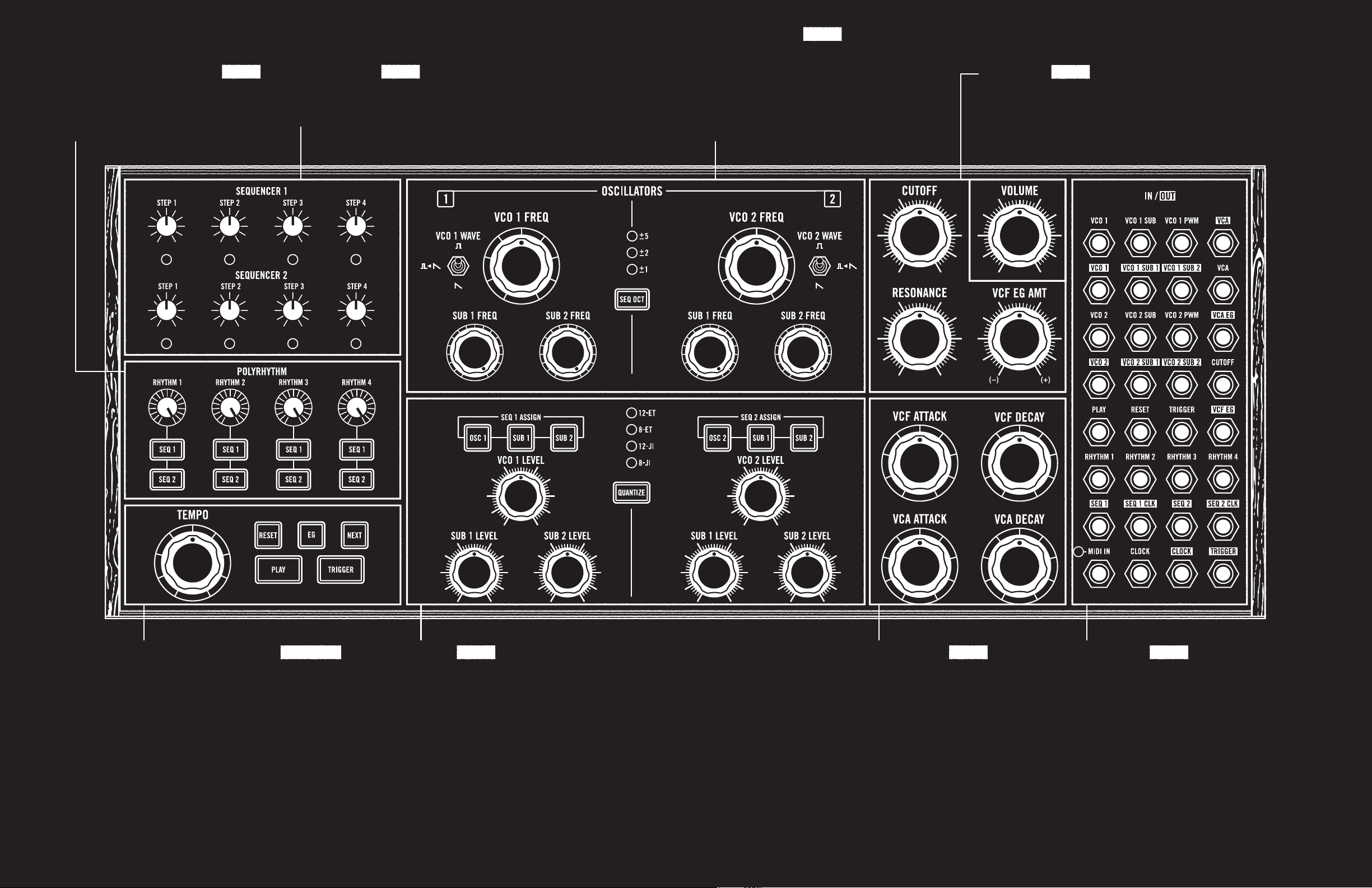
RHYTHM GENERATORS
Dividing the tempo creates a new rhythm.
Each of the four rhythm generators can drive
one or both sequencers. Combine rhythms
for exciting polyrhythms.
PAGE 30 PAGE 26
SEQUENCER
Sequencer 1 controls VCO 1 (and its subs).
Sequencer 2 controls VCO 2 (and its subs).
Each sequencer has four tunable steps.
OSCILLATORS
Two analog oscillators (VCO 1, VCO 2) form the
foundation of the sound. Change the waveform to
select a new timbre. Each VCO can be continuously
tuned over a specific range, or quantized to the steps
in one of four scales. Two subharmonic oscillators
per VCO are individually tunable to one of the first
16 undertones of the VCO’s current pitch.
PAGE 18
FILTERS
The famous Moog ladder filter provides
excellent timbre control. This VCF operates
as a low-pass, four-pole (-24dB/octave) filter.
Resonance control is provided.
PAGE 23
TEMPO & TRANSPORT
The tempo drives the rhythm generators, which in
turn drive the sequencers. The transport controls
start and stop the sequencers, advance to the
next step, and more.
SUBHARMONICON
MIXER
The mixer allows the levels of all six Subharmonicon
sound sources (VCO 1, SUB 1, SUB 2 and VCO 2,
SUB 1, SUB 2) to be set individually to create the
perfect mix. The combined signal is sent from the
mixer to the filter for further sound-shaping. (This
section is also home to the quantize and sequencer
assign functions.)
6 7
PAGE 21 PAGE 24 PAGE 31PAGE 25 & 28
ENVELOPES
Two envelope generators define how
the sound changes over time. The VCF
EG controls the attack time and decay
time of the filter (VCF); the VCA EG
controls the volume (VCA).
PATCHBAY
This patchbay offers 32 connections
(17 inputs and 15 outputs) for connecting to
other modular or semi-modular synthesizers
and audio equipment. MIDI data can be received
at the MIDI IN jack using the included Type A
MIDI adapter at the MIDI IN jack.
Page 7
UNPACKING & INSPECTION
Check the contents of the shipping carton. Be careful when unpacking your new Moog Subharmonicon
so that nothing is lost or damaged. We recommend saving the carton and all packing materials in case
you ever need to ship the instrument for any reason.
Subharmonicon ships with the following items:
Subharmonicon Semi-Modular Analog Polyrhythmic Synthesizer
1.
Power Supply
2.
DIN Socket to 3.5mm Plug (Type A) MIDI Adapter
3.
Patch Sheet Overlays
4.
Owner’s Manual
5.
Patch Cables
6.
Registration Card
7.
What you will need:
1.
Headphones with a 1/4” TRS plug, or a 1/4” TS instrument cable and an amplified speaker
2.
A properly wired AC outlet
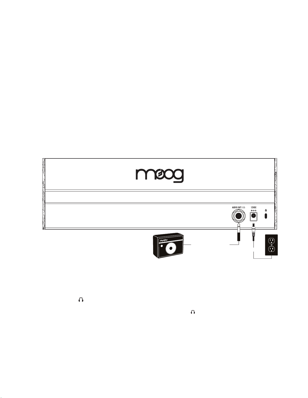
SETUP & CONNECTIONS
POWER
Plug the included power adapter into the
12VDC power jack on the rear panel of your
Subharmonicon.
NOTE: There is no power switch on your Subharmonicon. Once connected to the power supply, the unit is On.
Subharmonicon is an analog instrument and should be allowed a few minutes to warm up before use. In cases
where it has been left in a cold car overnight, for example, it may take even longer for the oscillator tuning to
stabilize. For optimized tuning do not operate your Subharmonicon in direct sunlight.
Amplifier or Headphones
Power Supply
AUDIO OUT /
With the Subharmonicon VOLUME knob turned all the way down (counterclockwise), plug one end
of a 1/4” instrument cable into the Subharmonicon AUDIO OUT / jack on the rear panel. Then plug
the other end into an amplified speaker or mixing console input. This jack can also be used with a set
of mono or stereo headphones, providing the same signal to each ear. Now, raise the VOLUME knob
(clockwise) to bring the sound to an appropriate level.
WARNING: Do not use a TRS (balanced) cable for line output applications, as this will cause phase cancellation
and can produce a very weak signal.
KENSINGTON SECURITY SLOT
Your Subharmonicon can be securely attached to a desk, stand, or other fixture by connecting a
Kensington security device to this slot.
8
Page 8
ABOUT SUBHARMONICON
Subharmonicon is an intensely creative semi-modular analog polyrhythmic synthesizer that uses
mathematical ratios to tune its four subharmonic oscillators, and to control the timing of its four
rhythm generators. Because these tuning and timing values are integer-derived, there is something
uniquely coherent about how patterns and phrases created using Subharmonicon blend together
musically. As with Mother-32 and DFAM, Subharmonicon conforms to the 60HP Eurorack format;
features aluminum rails, finished wood side pieces, an extensive patchbay; and can perform as
a standalone electronic instrument.
2 VOLTAGE CONTROLLED
OSCILLATORS (VCOs)
Each VCO features two
additional subharmonic
oscillators
POLYRHYTHM SECTION:
4 RHYTHM GENERATORS
Each rhythm generator can be
set to drive a single sequencer –
or both
TWO 4-STEP SEQUENCERS
Each sequencer controls any
combination of its associated
VCO, SUB 1, and SUB 2
2 ENVELOPE GENERATORS
Two Attack/Decay envelope
generators control the VCF
and VCA
RESONANT MOOG FILTER
4-pole (-24 db/octave) low-pass
Moog ladder filter
PATCHIN G
32-point modular patchbay
oering 17 inputs and 15 outputs
9
Page 9
INTRODUCTION
A BRIEF HISTORY
Throughout the 1960s and 70s, groundbreaking artists like Herb Deutsch, Wendy Carlos, and Keith
Emerson were looking for new ways to explore electronic sound, and found themselves collaborating
with electronic instrument pioneer Bob Moog to create the instruments of their dreams. If we set our
clocks back to the 1930s, we find a similar situation. Cutting-edge musicians and composers such
as Henry Cowell, Joseph Schillinger, Paul Hindemith, and Oskar Sala were teaming up with the likes
of Leon Theremin (of Theremin fame) and Freidrich Trautwein to create the instruments needed to
bring their musical visions to life. These were heady times for composers, performers, and instrument
creators. Electricity and electrical circuitry held the promise of a mechanical prowess that could
enhance and extend existing compositional and performance abilities.
Freidrich Trautwein’s Trautonium was a vacuum tube electronic instrument that created a rich sawtooth
wave, tamed by a resonant low-pass filter, to create an early model of subtractive synthesis. Oskar Sala
eventually took over development of the Trautonium (later renamed the Mixtur-Trautonium), adding a
series of subharmonic oscillators that generated undertones pitched at fractions of the original pitch
(and not the overtones created at multiples of the original pitch, such as in Laurens Hammond’s tonewheel organ). Around the same time, Henry Cowell and Joseph Schillinger collaborated with Leon
Theremin on the Rhythmicon, an instrument capable of sounding up to 16 polyrhythm generators
simultaneously. Schillinger’s theories included combining rhythmic “generators” occurring at integerrelated durations.
Their work contained the seeds of today’s algorithmic composition software. The subharmonic
oscillators of the Mixtur-Trautonium were derived from the oscillator’s initial pitch, while the
Rhythmicon created polyrhythms that were derived from the original tempo. It is these concepts
of subharmonics and polyrhythms that form the historic roots of your Moog Subharmonicon, an
inspiring and innovative semi-modular analog polyrhythmic synthesizer.
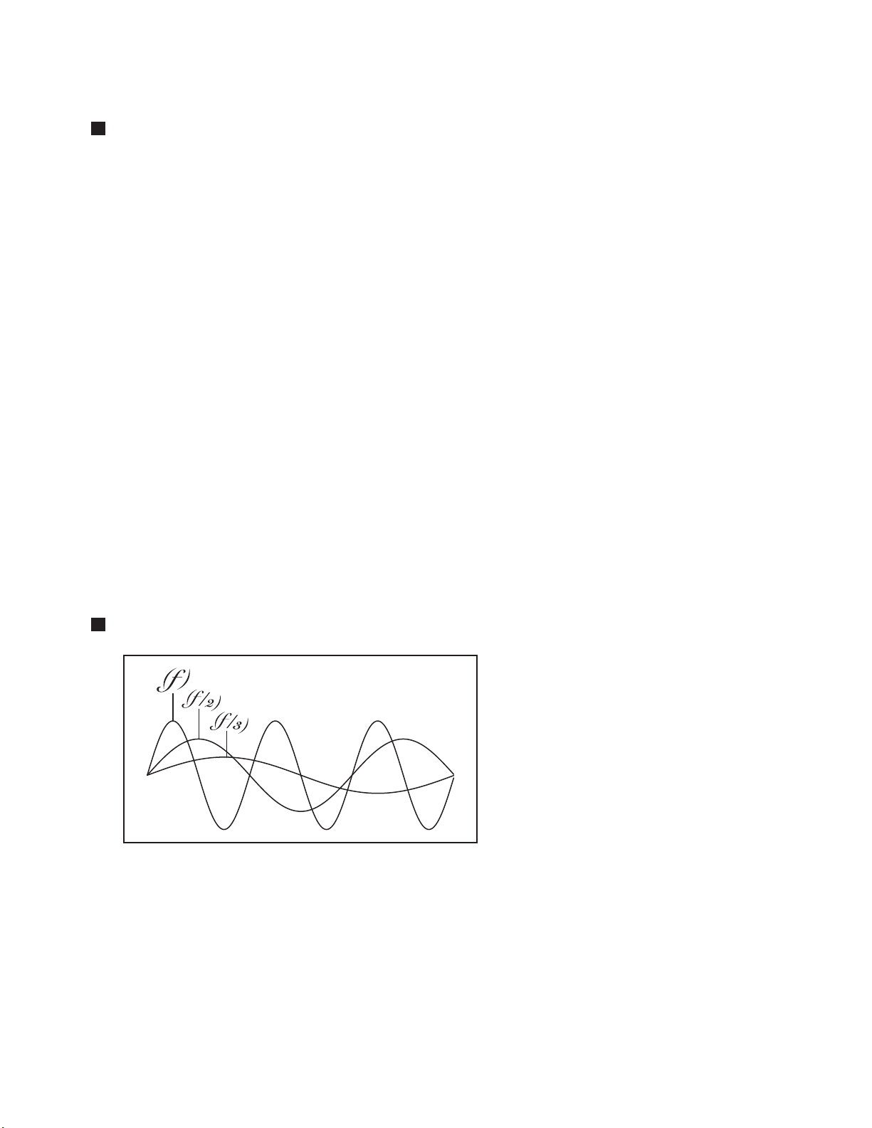
UNDERSTANDING SUBHARMONICS
In the world of synthesizers and electronic
keyboards, we often refer to harmonics
– a series of overtones occurring at
fixed mathematical intervals above the
fundamental pitch that are responsible
for a wave’s shape and timbre. A wave
shape may contain certain harmonics in
a particular pattern of relative strength,
for example. We know that pitch can be
modified by changing the length of an
organ pipe, a guitar string, the column
of air in a trumpet, etc. The remarkable
thing is that the ratio between the original pitch and the altered pitch always follows the same pattern
– the harmonic series. So if we have a guitar string vibrating at a frequency (ƒ) of 440 Hz, and we halve
its length by playing at the 12th fret, the string sounds one octave higher (ƒ*2) at 880 Hz, or double
the original frequency. One-third the length produces the fifth above that (ƒ*3), etc. In every case,
multiplying the original frequency by an integer creates a specific harmonic.
Creating an undertone, or a subharmonic, is more challenging in the physical world. Instead of
multiplying the original frequency by an integer value, we must divide by an integer value. We cannot
simply build a guitar that becomes twice as large in order to play the first subharmonic, one octave
down in pitch at 220 Hz (ƒ/2) from the original pitch (ƒ) of 440 Hz.
10
Page 10
UNDERSTANDING SUBHARMONICS (Continued)
Fortunately, electronic circuits can create subharmonics quite easily. Regardless of whether the initial
frequency (ƒ) is being multiplied by an integer to create an overtone, or divided by an integer to create
a subharmonic undertone, the ratios and intervals will remain the same, as in the following examples:
Original Note
2nd Harmonic
3rd Harmonic
4th Harmonic
5th Harmonic
6th Harmonic
...
15th Harmonic
16th Harmonic
Overtones
(f)
(f) * 2
(f) * 3
(f) * 4
(f) * 5
(f) * 6
Continued
(f) * 15
(f) * 16
Original Note
2nd Subharmonic
3rd Subharmonic
4th Subharmonic
5th Subharmonic
6th Subharmonic
...
15th Subharmonic
16th Subharmonic
Undertones
(f)
(f) / 2
(f) / 3
(f) / 4
(f) / 5
(f) / 6
Continued
(f) / 15
(f) / 16
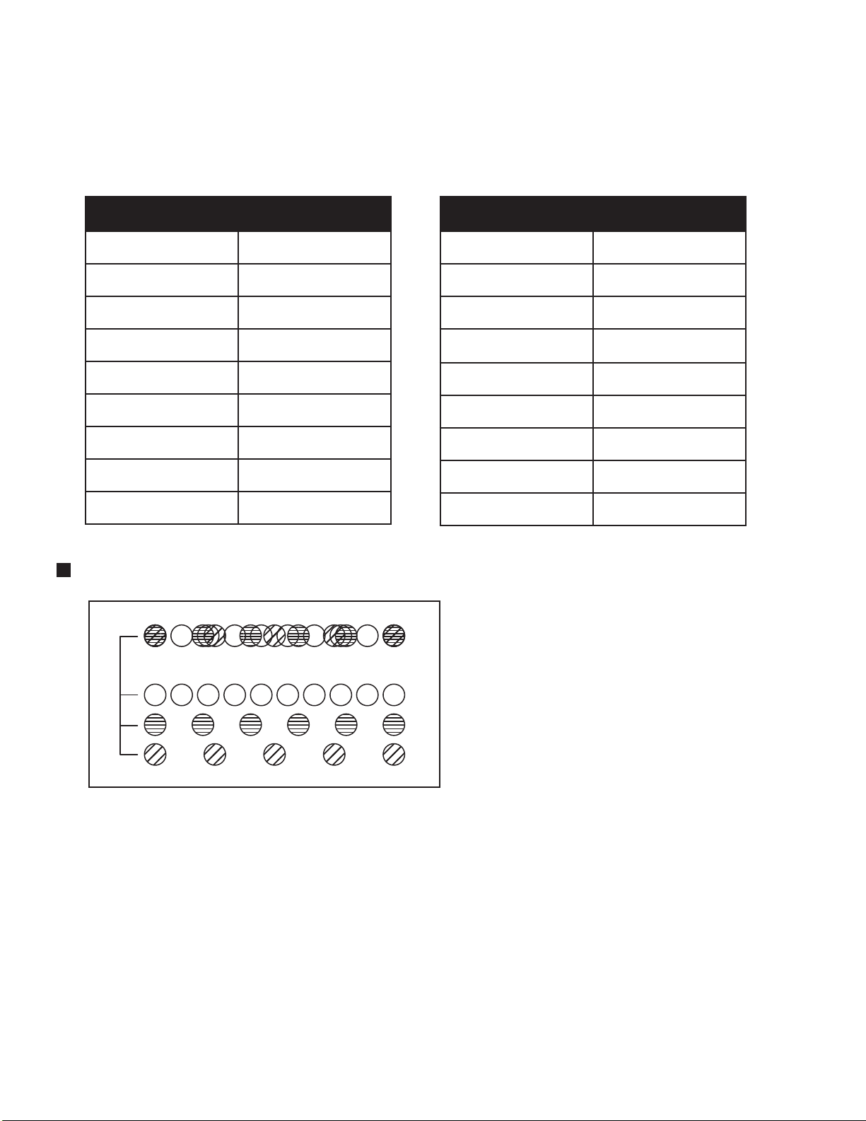
UNDERSTANDING POLYRHYTHMS
Polyrhythms employ multiple rhythms
playing at once to create complex,
interweaving phrases. In the same
way that a subharmonic oscillator uses
an integer value to modify the initial
pitch (ƒ) of an oscillator to create a
musically related subharmonic, each
Subharmonicon rhythm generator uses
an integer value to divide the current
clock value (t) to create a new rhythm.
These individual rhythm generators
are used to drive one or both of the
Subharmonicon’s sequencers. Once you engage more than one rhythm generator, you will hear how
the dierent clock divisions can play o or against one another to synthesize a polyrhythm. Because
each rhythm generator references the same clock, they will eventually re-sync to the same downbeat,
causing the overarching polyrhythm to finally repeat. In this way, you can think of the rhythm
generators as combining to create one larger, cyclic pattern. Rhythm generators can be switched on
and o and assigned to dierent sequencers as you perform, creating complex polyrhythmic content –
as well as some truly unique phrasing and grooves.
11
Page 11
EXPLORING YOUR SUBHARMONICON
If you are new to synthesizers, or if you just want a deeper understanding of your new instrument
before you get started, join us for a quick hands-on Subharmonicon tour. Knowing what to expect as you
explore the controls will make it easier to achieve your musical goals. You can also begin by following
some of the patch examples (beginning on page 45) and tweaking them to suit your own taste.
START YOUR EXPLORATION
To begin, connect Subharmonicon to either a set of headphones or a monitoring system, and set the
controls on your Subharmonicon to match the settings shown above.
LISTENING TO VCO 1
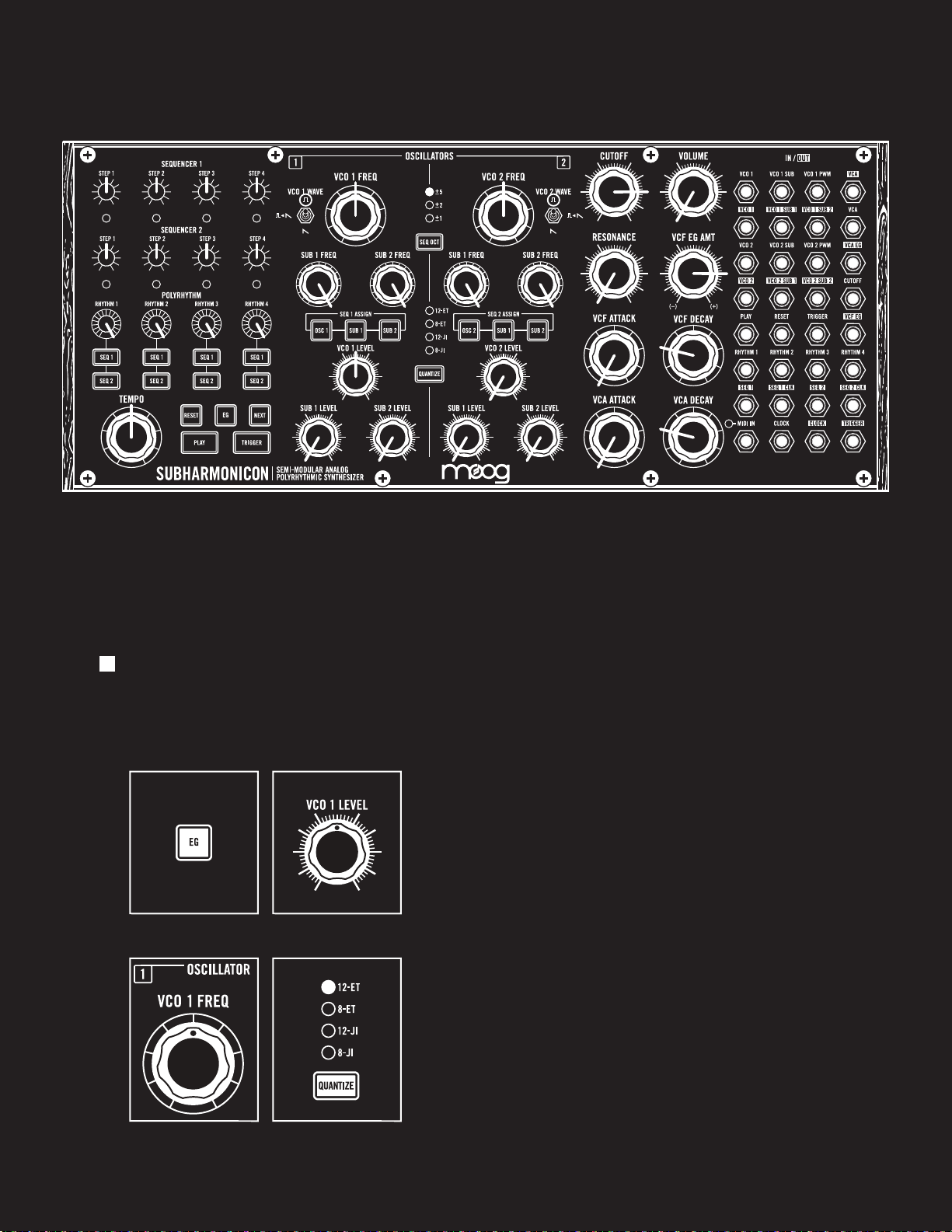
Hold the EG button until it begins to blink. This locks the
VCF EG and VCA EG at their highest values, allowing you
to hear what is happening as you experiment. Raise the
VCO 1 LEVEL knob to the halfway (or center) point, and
then raise the VOLUME knob to a comfortable listening
level. You are now hearing VCO 1.
TUNING VCO 1
Press the QUANTIZE button until no lights are lit
(unquantized), and rotate the VCO 1 FREQ knob to listen
to the tuning range of VCO 1, and you will hear the pitch
change smoothly over a wide range. Next, press the
QUANTIZE button until the 12-ET LED indicator is lit.
Now, as you rotate the VCO 1 FREQ knob, you will hear
the frequency step from note to note, following the steps
of a 12-tone equal tempered scale.
12
12
Page 12
EXPLORING YOUR SUBHARMONICON (Continued)
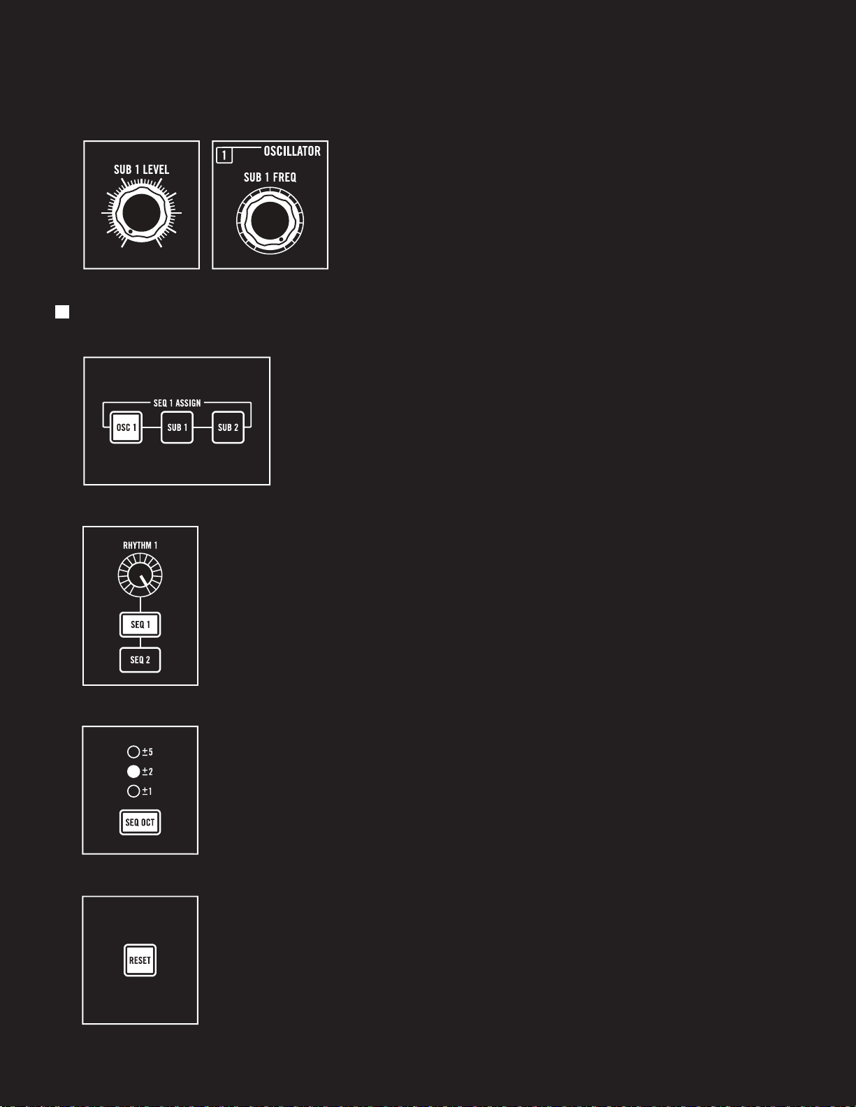
ADDING IN A SUBHARMONIC OSCILLATOR
Rotate the SUB 1 LEVEL knob clockwise and you will hear
the sound of the first subharmonic oscillator associated
with VCO 1 mixed in with the sound of VCO 1. With the
SUB 1 FREQ knob all the way clockwise, VCO 1 and SUB 1
are playing in unison. As you rotate the SUB 1 FREQ knob
slowly counter-clockwise, you will hear the pitch of SUB 1
step through the available undertones.
CREATING A SEQUENCE
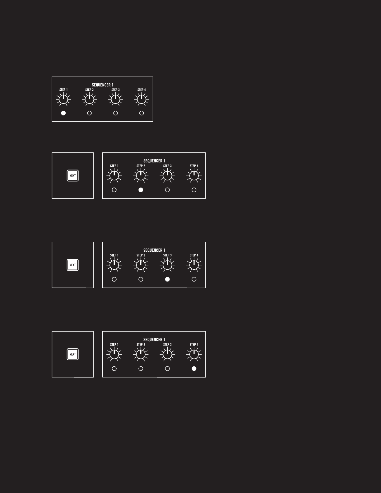
INTRODUCTION
Before we can create a sequence, we need to let Subharmonicon
know what our intentions are. First, press the OSC 1 button (located
in the SEQ 1 ASSIGN buttons) so that it is lit. This allows the
individual STEP knobs of Sequencer 1 to modify the pitch of VCO 1.
Next, press the SEQ 1 button (located under the RHYTHM 1 knob) so that it is
lit. This step attaches a rhythm source to Sequencer 1, so that we can use the
NEXT and RESET buttons to navigate the individual steps of Sequencer 1.
Finally, use the SEQ OCT button to select the range, in octaves, of the
sequencer STEP knobs. An LED will indicate the current selection. Use the
SEQ OCT button to cycle through the available options. For now, let’s use
the ±2 option.
Press the RESET button to return the sequencer(s) to Step 1.
This will also reset the rhythm generators to their starting position.
13
13
Page 13
EXPLORING YOUR SUBHARMONICON (Continued)
CREATING A SEQUENCE (Continued)
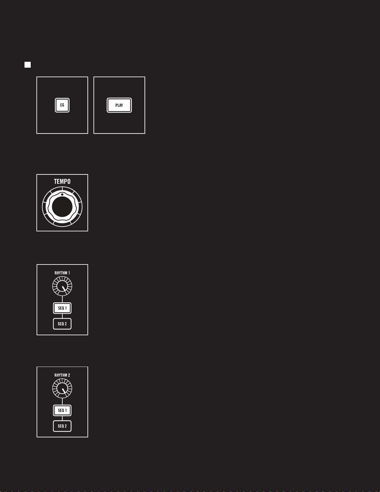
TUNING STEP 1
Step 1 is now selected, and the LED indicator located under
the STEP 1 knob will be lit. As you listen, rotate the STEP 1
knob to set a pitch for Step 1 of your sequence.
ADVANCING TO STEP 2
Press the NEXT button to advance to Step 2
of the sequence. The LED indicator located
under the STEP 2 knob will be lit. As you
listen, rotate the STEP 2 knob to set a pitch
for Step 2 of your sequence.
ADVANCING TO STEP 3
Press the NEXT button to advance to Step 3
of the sequence. The LED indicator located
under the STEP 3 knob will be lit. As you
listen, rotate the STEP 3 knob to set a pitch
for Step 3 of your sequence.
ADVANCING TO STEP 4
Press the NEXT button to advance to
Step 4 of the sequence. The LED indicator
located under the STEP 4 knob will be lit.
As you listen, rotate the STEP 4 knob to set
a pitch for Step 4 of your sequence.
NOTE: You can use the NEXT button to
continually cycle through the steps, so you
can change the STEP knob values until you
have a pattern you like.
14
14
Page 14
EXPLORING YOUR SUBHARMONICON (Continued)
PLAYING YOUR SEQUENCE
Press the blinking EG button so that it remains lit. This
releases the envelope generators from their held state, so
that each step of the sequencer will now trigger the EGs.
Now, press the PL AY button. Your sequence will begin
to play.
ADJUSTING THE TIMING
Rotate the TEMPO knob to see how the sequencer and rhythm generator
tempos are aected.
Rhythm Generator 1 is currently producing a division of the master tempo to
drive Sequencer 1, indicated by the illuminated SEQ 1 button. Notice that as
you turn the RHYTHM 1 knob, you are selecting one of 16 discrete steps. These
steps are produced by dividing the tempo by an integer value of 1 through 16.
NOTE: This is the same method (dividing by an integer value of 1 through 16) that is
used for deriving the pitch of a subharmonic oscillator.
CREATING A POLYRHYTHM
As your sequence continues to play, press the SEQ 1 button associated with
Rhythm Generator 2. You are now using the output of two rhythm generators
to drive Sequencer 1, creating a polyrhythm. As you rotate the RHYTHM 2 knob
further from and closer to the RHYTHM 1 knob position, you can hear how the
complexity of this polyrhythm changes.
TIP: As you are trying new polyrhythm settings, you can use the RESET button to
instantly set the sequencer(s) and the rhythm generators to their initial starting
position, inviting you to explore how the polyrhythm unfolds and cycles back.
15
15
Page 15

EXPLORING YOUR SUBHARMONICON (Continued)
EXPLORING THE FILTER
As your sequence continues to play, you can rotate the
CUTOFF and RESONANCE knobs and listen to how changing
the filter settings can aect the timbre of your sequenced
sound. The VCF EG AMT knob defines how much eect the
VCF Envelope Generator (VCF EG) will have on the filter
settings. By turning the RESONANCE knob toward maximum
and experimenting with the CUTOFF knob, you can coax the
filter to “chirp” as it approaches a self-resonant state. Try it!
CHANGING THE WAVE
As you explore the ways dierent filter settings aect the timbre of each note,
you can also use the VCO 1 WAVE switch to hear how dierent waves aect the
overall sound.
TWEAKING THE ENVELOPES
As your sequence continues to play, you can change the
Attack and Decay rates for both the VCF EG and the VCA EG.
The VCF EG changes the Cuto Frequency of the Voltage
Controlled Filter (VCF) over time; the VCA EG changes
the Voltage Controlled Amplifier (VCA) setting, or output
volume, over time. Using relatively quick attack and decay
rates can be best for percussive eects and punchy basses
or leads. Slower decay times can add more of a drone or
atmospheric feel to the sound.
And don’t forget, the VCF EG AMT knob is bi-directional,
with the center position creating no eect. Rotating the
VCF EG AMT clockwise adds a positive amount of envelope
control, while rotating this knob counter-clockwise adds a
negative amount of envelope control, creating some very
useful and unusual eects.
16
16
Page 16
EXPLORING YOUR SUBHARMONICON (Continued)
SUMMARY
In this exploration of your Subharmonicon, we have used only one VCO, one subharmonic oscillator,
one sequencer, and two rhythm generators — working with each to become familiar with how they
contribute to your overall sound.
This is only scratching at the surface of the sound design potential and rhythmic phrases that are
possible within this instrument once all of its oscillators, sequencers, and rhythm generators are
dialed up. We hope that this exercise provides you with a foundation from which you can continue
your experimentations.
Keep in mind that Subharmonicon is a performance instrument. Changing the rhythm generator
assignment in real time, using the RESET button, pushing the SEQ ASSIGN buttons, and tweaking
the filter controls and mix levels can result in an engaging and fluid electronic music event.
UNDERSTANDING TUNING SYSTEMS & TEMPERAMENT
When talking about musical instruments, tuning systems are the method
used to determine which frequencies or pitches an instrument is able to play.
Subharmonicon’s sequencer section is unique in its ability to easily work within
two dierent tuning systems: just intonation (JI) and equal temperament (ET).
Just intonation is an older approach to generating musical scales based around
whole number ratios (i.e. the harmonic series). So, if we wanted to work in the
“just scale” of C major, we’d be determining our note values based on whole
number fractions related to C’s frequency (e.g. C=1/1, D=9/8, E=5/4, F=4/3,
G = 3/2, A=5/3, B=15/8, C=2/1, etc.). Working in just intonation becomes
complicated when you want to play music in more than one key. Because a just scale’s note values are
based around a root note’s frequency, the moment you try and modulate to a dierent key, all of your
notes will sound incorrect since they were derived from the original root note; this is when the idea of
a temperament becomes important. A temperament is a tuning system that compromises the pure
intervals of just intonation in order to achieve better harmonic relationships between diering keys.
The most commonly used temperament is equal temperament.
Equal temperament is based around the idea of dividing an octave into 12 evenly spaced semitones,
so that scale intervals will be the same in any key. This creates scales in which all intervals are imperfect
(when compared to just intonation) but still tolerable to the ear, and by making all the note values
equally ‘incorrect’ you can easily write music that jumps between keys without needing to retune
your instrument. Equal temperament has been the standard tuning system in western music since
the 18th century, and is what most people will consider as sounding “in tune,” despite the fact that
just intonation is technically more in tune due to its basis in the harmonic series.
As a listening exercise, try building up a complex chord using the VCO FREQ and SUB FREQ
knobs, and use the QUANTIZE button to listen to how your chord voicing changes with the dierent
quantization settings. One aspect that should be especially noticeable in just intonation, is the lack
of frequency beating typically heard in minor chords.
17
Page 17
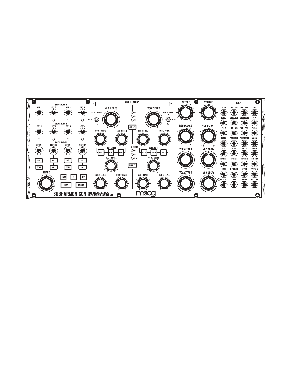
PANEL CONTROLS & FUNCTIONS
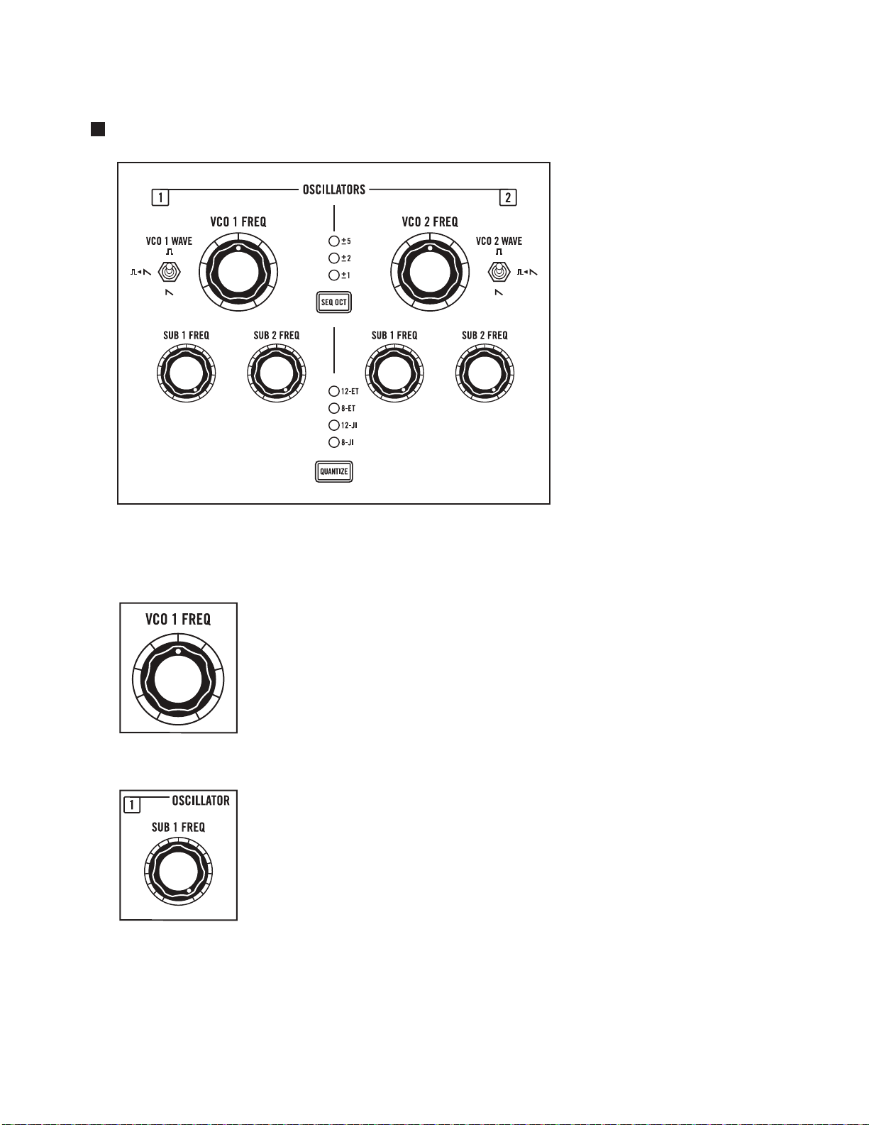
THE OSCILLATORS
In the synthesizer world, the
primary role of an oscillator is
to generate sound. Oscillators
can be assigned a wave shape
to determine the initial timbre
of the sound, oscillators
can be tuned to specific
frequencies, and an oscillator
can be played — its pitch
varied by a control voltage
source such as a keyboard
or sequencer.
Each voltage controlled
oscillator (VCO 1 and
VCO 2) is equipped with two
subharmonic oscillators.
These subharmonic oscillators
can be independently set to a
specific note, or subharmonic,
of the undertone series.
OSCILLATOR 1 PARAMETERS
VCO 1 FREQ
Rotating this knob will set the initial frequency, or pitch, of VCO 1. The range
of this knob is four octaves. Rotating the VCO 1 FREQ knob fully counterclockwise will specify the initial pitch as Middle C (262 Hz) on a piano. Rotating
this knob fully clockwise will specify the initial pitch as the highest C (4186 Hz)
on a piano.
NOTE: Engaging the QUANTIZE settings will limit the available values for the VCO 1
FREQ knob to the specific scale steps set by the current value of the QUANTIZE button.
SUB 1 FREQ (VCO 1)
The pitch or frequency of SUB 1 (the first subharmonic oscillator of VCO 1) is
derived from the initial frequency (ƒ) of VCO 1. The SUB 1 frequency is equal to
the initial pitch of VCO 1, divided by a whole number integer value from 1 to 16.
As you rotate the SUB 1 FREQ knob, you are actually selecting the integer value
used. You can hear the pitch of SUB 1 change in stepped values, starting with 1
[unison tuning to VCO 1: (ƒ)/1 = (ƒ)] when this knob is rotated fully clockwise,
and proceeding in steps to a value of 16 as this knob is rotated counterclockwise. Each one of these values produces a note on the undertone scale
derived from the initial pitch of VCO 1.
18
Page 18
THE OSCILLATORS (Continued)
OSCILLATOR 1 PARAMETERS (Continued)
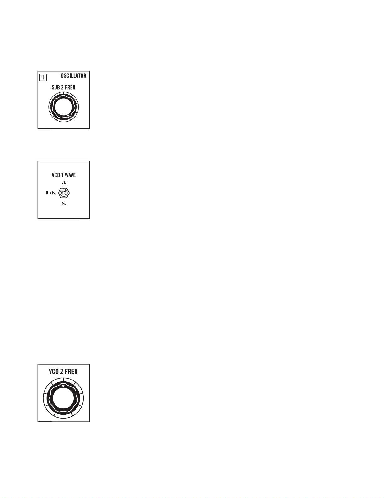
SUB 2 FREQ (VCO 1)
The pitch or frequency of SUB 2 (the second subharmonic oscillator of VCO 1) is
derived from the initial frequency (ƒ) of VCO 1. The SUB 2 frequency is equal
to the initial pitch of VCO 1, divided by a whole number integer value from
1 to 16. As you rotate the SUB 2 FREQ knob, you are actually selecting the
integer value used. You can hear the pitch of SUB 2 change in stepped values,
starting with 1 [unison tuning to VCO 1: (ƒ)/1 = (ƒ)] when this knob is rotated
fully clockwise; and proceeding in steps to a value of 16 as this knob is rotated
counter-clockwise. Each one of these values produces a note on the undertone
scale derived from the initial pitch of VCO 1.
WAVEFORM (VCO 1)
The waveform being output by VCO 1, SUB 1, and SUB 2 is determined by this
three-position switch.
UP: In this highest position, a square wave is output from VCO 1, SUB 1, and
SUB 2. Square waves produce a hollow sound, providing a rich starting point
for nasal clarinet and bass sounds.
MIDDLE: The middle position is a special case. With the switch in this position,
SUB 1 and SUB 2 will both output sawtooth waves. However, VCO 1 will output a square (pulse) wave.
By default, the sawtooth output of SUB 1 is normalled for use as a PWM (Pulse Width Modulation)
source for the square wave of VCO 1. PWM can change the width of the pulse wave, altering its timbre
which is popular for creating string-type sounds.
DOWN: In this lowest position, a sawtooth wave is output from each. In addition to creating thick,
brassy sounds, the sawtooth wave also lends itself to powerful lead and bass sounds.
TIP: In the middle position, the PWM of VCO 1, caused by the audio-rate frequency of SUB 1, can appear to add
a second pitched component to VCO 1, even when the SUB 1 LEVEL knob is at its minimum position.
NOTE: The normalled connection described above can be overridden by connecting a control signal to the
VCO 1 PWM input jack of the patchbay.
OSCILLATOR 2 PARAMETERS
The Oscillator 2 parameters function in the same way as the Oscillator 1 parameters.
VCO 2 FREQ
Rotating this knob will set the initial frequency, or pitch, of VCO 2. The range
of this knob is four octaves. Rotating the VCO 2 FREQ knob fully counter-
clockwise will specify the initial pitch as Middle C (262 Hz) on a piano. Rotating
this knob fully clockwise will specify the initial pitch as the highest C (4186 Hz)
on a piano.
NOTE: Engaging the QUANTIZE settings will limit the available values for the
VCO 2 FREQ knob from continuous to the specific scale steps set by the current
value of the QUANTIZE button.
19
Page 19

THE OSCILLATORS (Continued)
OSCILLATOR 2 PARAMETERS (Continued)
SUB 1 FREQ (VCO 2)
The pitch, or frequency of SUB 1 (the first Subharmonic Oscillator of VCO 2) is
derived from the initial frequency (ƒ) of VCO 2. The SUB 1 frequency is equal to
the initial pitch of VCO 2, divided by a whole number integer value from 1 to 16.
As you rotate the SUB 1 FREQ knob, you are actually selecting the integer value
used. You can hear the pitch of SUB 1 change in stepped values, starting with 1
[unison tuning to VCO 2: (ƒ)/1 = (ƒ)] when this knob is rotated fully clockwise,
and proceeding in steps to a value of 16 as this knob is rotated counterclockwise. Each one of these values produces a note on the undertone scale
derived from the initial pitch of VCO 2.
SUB 2 FREQ (VCO 2)
The pitch, or frequency of SUB 2 (the second Subharmonic Oscillator of VCO 2)
is derived from the initial frequency (ƒ) of VCO 2. The SUB 2 frequency is equal
to the initial pitch of VCO 2, divided by a whole number integer value from 1 to 16.
As you rotate the SUB 2 FREQ knob, you are actually selecting the integer
value used. You can hear the pitch of SUB 2 change in stepped values, starting
with 1 [unison tuning to VCO 2: (ƒ)/1 = (ƒ)] when this knob is rotated fully
clockwise, and proceeding in steps to a value of 16 as this knob is rotated
counter-clockwise. Each one of these values produces a note on the undertone
scale derived from the initial pitch of VCO 2.
WAVEFORM (VCO 2)
The waveform being output by VCO 2, SUB 1, and SUB 2 is determined by this
three-position switch.
UP: In this highest position, a square wave is output from VCO 2, SUB 1, and
SUB 2. Square waves produce a hollow sound, providing a rich starting point
for nasal clarinet and bass sounds.
MIDDLE: The middle position is a special case. With the switch in this position,
SUB 1 and SUB 2 will both output sawtooth waves. However, VCO 2 will output a square (pulse) wave.
By default, the sawtooth output of SUB 1 is normalled for use as a PWM (Pulse Width Modulation)
source for the square wave of VCO 2. PWM can change the width of the pulse wave, altering its timbre
which is popular for creating string-type sounds.
DOWN: In this lowest position, a sawtooth wave is output from each. In addition to creating thick,
brassy sounds, the sawtooth wave also lends itself to powerful lead and bass sounds.
TIP: In the middle position, the PWM of VCO 2 caused by the audio-rate frequency of SUB 1 can appear to add a
second pitched component to VCO 2, even when the SUB 1 LEVEL knob is at its minimum position.
NOTE: The normalled connection described above can be overridden by connecting a control signal to the VCO 2
PWM input jack of the patchbay.
20
Page 20

THE OSCILLATORS (Continued)
SHARED OSCILLATOR PARAMETERS
Quantizing focuses the continuous sweep of an oscillator into stepped voltages th at, in the case
of Subharmonicon, generate either a 12-tone or 8-tone division of the octave (with just or equal
temperaments). Learn more about tuning systems and tempe rament on page 17. W hen the Quantize
function is engaged, rotating the VCO 1 FREQ knob or the VCO 2 FR EQ knob will se lect steps of the
scale, as defined by the current Quantize setting. The Quantize function is shared by both oscillators;
it cannot be set individually.
NOTE: By default, the SEQ 1 and SEQ 2 output jacks will output a control voltage that reflects the current
Quantize settings. This behavior can be disengaged by pressing and holding the QUANTIZE button until the
LED flashes, at which point the Oscillators will continue to respect the current Quantize settings, while the
SEQ 1 and SEQ 2 output jacks will remain unquantized at the patchbay.
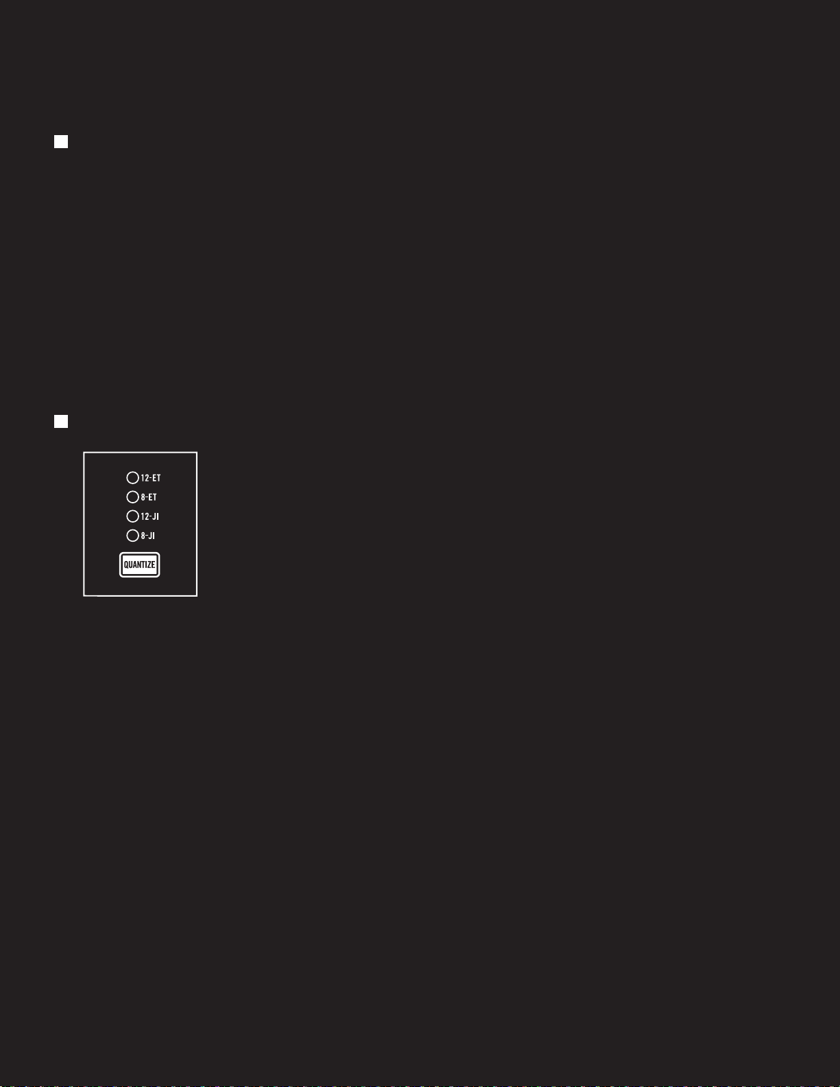
QUANTIZE
There are four quantized settings. Pressing the QUANTIZE button will cycle
through the available settings, with an LED indicating the current selection.
With all LEDs o, no Quantization value is selected, and the Quantize
function is o.
12 - E T: This option selects a Chromatic (12-step) scale using Equal Temperament
(ET), which is the basis for Western keyboard music.
8-ET: This option selects a Diatonic (8-step) scale using Equal Temperament (ET).
12-JI: This quantize option uses a Chromatic (12-step) scale using Just
Intonation (JI).
8-JI: This quantize option uses a Diatonic (8-step) scale using Just Intonation (JI).
THE MIXER
The mixer sets the
individual levels of all six
Subharmonicon sound
sources. The combined
signal exits the mixer and
enters the filter section.
NOTE: The mixer can be pushed
into a warm distortion by
setting the sound sources near
their maximum levels. Setting
the mixer to moderate levels
will produce a cleaner sound.
VCO 1 LEVEL
This knob sets the level of the VCO 1 signal. Rotating this knob clockwise
will raise the level; rotating this knob counter-clockwise will lower the level.
21
Page 21

THE MIXER (Continued)
SUB 1 LEVEL (VCO 1)
This knob sets the level of SUB 1 — the first subharmonic oscillator associated
with VCO 1. Rotating the knob clockwise raises the level; rotating it counter-
clockwise lowers the level.
SUB 2 LEVEL (VCO 1)
This knob sets the level of SUB 2 — the second subharmonic oscillator
associated with VCO 1. Rotating the knob clockwise raises the level; rotating it
counter-clockwise lowers the level.
VCO 2 LEVEL
This knob sets the level of the VCO 2 signal. Rotating this knob clockwise will
raise the level; rotating this knob counter-clockwise will lower the level.
SUB 1 LEVEL (VCO 2)
This knob sets the level of SUB 1 — the first subharmonic oscillator associated
with VCO 2. Rotating the knob clockwise raises the level; rotating it counter-
clockwise lowers the level.
SUB 2 LEVEL (VCO 2)
This knob sets the level of SUB 2 — the second subharmonic oscillator
associated with VCO 2. Rotating the knob clockwise raises the level; rotating it
counter-clockwise lowers the level.
22
Page 22

THE FILTER
The combined output signal from the mixer is internally wired to the input of the filter. Subharmonicon
relies on a Voltage Controlled Filter (VCF) to dynamically shape the timbre of a sound by selectively
removing frequencies above the Filter’s Cuto Frequency. This low-pass filter is of the famous Moog
ladder type.
NOTE: Technically, this is a four-pole low-pass ladder filter providing 24 dB of attenuation per octave above the
Cutoff Frequency.
CUTOFF
This knob sets the Cuto Frequency for the Filter, from 20 Hz to 20k Hz.
Frequencies below the Cuto Frequency will be allowed to pass; frequencies
above the Cuto Frequency will be attenuated at a rate of 24 dB per octave.
Turning the CUTOFF knob clockwise opens the filter by raising the Cuto
Frequency, resulting in a brighter and more articulate sound.
Turning the CUTOFF knob counter-clockwise closes the filter by lowering the
Cuto Frequency, resulting in a thicker or darker sound.
RESONANCE
Resonance allows a certain amount of signal from the filter’s output to be
routed back to the filter’s input. This action gives added sonic emphasis via
a resonant peak that occurs at the Filter Cuto Frequency.
Turn the RESONANCE knob clockwise to increase the level of this resonant
peak. Turn the RESONANCE knob counter-clockwise to decrease the level
of this resonant peak. Pushing the RESONANCE level to its maximum and
lowering the CUTOFF value can cause the filter to self-oscillate.
THE AMPLIFIER (VCA)
Before the sound leaves your Subharmonicon, it passes through the Voltage Controlled Amplifier to
attain the desired level. It is here that the Subharmonicon volume can be controlled.
VOLUME
The output level of the AUDIO OUT / jack is controlled via this knob.
Rotating this knob clockwise increases the Volume, rotating this knob counterclockwise decreases the Volume.
23
Page 23

THE ENVELOPE GENERATORS (EG)
An envelope generator creates a control voltage that changes in value over time. Subharmonicon
contains two envelope generators, each with an Attack stage and a Decay stage. The first EG adds
control to the Cuto Frequency of the VCF, or filter; the second EG adds control to the output level
of the VCA.
VCF EG
The VCF EG produces a time-variant control voltage that modulates the setting of the
VCF Cuto Frequency.
VCF ATTACK
The VCF ATTACK knob determines how much time is required for the Attack
stage of the VCF EG to rise (or fall) from the level specified by the CUTOFF
knob to the maximum Cuto Frequency achieved using the VCF EG AMT knob,
with a range of 1 millisecond to 10 seconds. Once a trigger or gate is received
by Subharmonicon — either from the internal sequencer or from an external
keyboard, via MIDI, etc. — the VCF EG will begin its cycle.
NOTE: The Subharmonicon VCF EG is unique in that, while in the Attack phase, the VCF
EG will not restart even when a new trigger or gate is received. Only once the Attack
phase has been completed can a new trigger or gate be received to restart the VCF EG.
VCF DECAY
The VCF DECAY knob determines how much time is required for the Decay
stage of the VCF EG to fall or rise from the Cuto Frequency achieved using
the VCF EG AMT knob to the level specified by the CUTOFF knob, with a range
of 5 milliseconds to 10 seconds. When a trigger is received, the VCF EG will
complete the Attack stage, and then proceed to the Decay stage. When a gate
is received, the VCF will complete the Attack stage and hold at the maximum
level until the gate ends, at which point the Decay stage will begin.
VCF EG AMT
This knob controls the amount, or depth, of change to the Cuto Frequency
caused by the VCF EG. Also note that this knob is bi-directional, with both
positive (clockwise) and inverse (counter-clockwise) values. In the center
position, the VCF EG has no eect. Positive (+) values will cause the VCF EG
to open the filter on the Attack stage, and close the filter on the Decay stage.
Inverse (–) values will close the filter during the Attack stage, and open the
filter on the Release stage.
VCA EG
The VCA EG produces a time-variant control voltage that modulates the attack and decay of the
Volume level.
VCA ATTACK
The VCA ATTACK knob determines how much time is required for the Attack
stage of the VCA EG to rise from zero to the level specified by the VOLUME
knob, from 1 millisecond to 10 seconds. Once a trigger or gate is received
by Subharmonicon — either from the internal sequencer or from an external
keyboard, via MIDI, etc. — the VCA EG will begin its cycle.
NOTE: The Subharmonicon VCA EG is unique in that while in the Attack phase, the
VCA EG will not restart even when a new trigger or gate is received. Only after the Attack
phase has been completed can a new trigger, or gate, be received to restart the VCA EG.
24
Page 24

THE ENVELOPE GENERATORS (EG) (Continued)
VCA DECAY
The VCF DECAY knob determines how much time is required for the Decay
stage of the VCA EG to fall from the level specified by the VOLUME knob
to zero, from 5 milliseconds to 10 seconds. When a trigger is received, the
VCA EG will complete the Attack stage, and then proceed to the Decay stage.
When a gate is received, the VCA will complete the Attack stage and hold at
the maximum level until the gate ends, at which point the Decay stage will begin.
TEMPO
Much of the Subharmonicon performance is derived from the TEMPO setting. This knob sets a base
clock rate that drives the timing of the four rhythm generators, which in turn drives the timing of the
two sequencers.
TEMPO
The TEMPO knob sets the initial clock rate for the sequencers and the rhythm
generators. The range of the TEMPO knob is from .333 Hz to 50 Hz. In the more
musical measure of tempo, this equates to a range of 20 BPM to 3,000 BPM
(Beats Per Minute), assuming 1 PPQ (Pulse Per Quarter-note).
NOTE: An analog clock signal connected to the CLOCK input jack of the patchbay will
override the internal clock and this TEMPO knob. A MIDI clock signal connected to the
MIDI IN input jack of the patchbay (using a five-pin DIN socket to 1/8” plug TYPE A MIDI
connector, such as the one provided with your Subharmonicon) will override both the
internal clock and any analog clock signals connected to the CLOCK input jack.
NOTE: Internal clock is 1 PPQ until a MIDI clock is detected. When MIDI clock is present,
the PPQ is 4 (16th notes).
25
Page 25

THE SEQUENCERS
Subharmonicon contains two identical sequencers. Each sequencer features four individual steps.
Each step includes a variable tuning knob and an LED to indicate the current active step. Sequencer 1 is
tied internally to OSC 1 and the subharmonic oscillators associated with OSC 1, and Sequencer 2 is tied
internally to OSC 2 and the subharmonic oscillators associated with OSC 2. In order for a sequencer
to play, it must receive clock information from at least one of the rhythm generators. Each sequencer
may be driven by any or all of the rhythm generators — opening the instrument up to a wide variety of
rhythmic possibilities.
NOTE: The patchbay allows the creation of new control paths to augment or replace the normalled sequencer
connections. For example, connecting the SEQ 1 output jack to the VCO 2 input jack would allow Sequencer 1
to modify the pitch of VCO 2, either alone (SEQ 2 ASSIGN OSC 2 button off/unlit), or in conjunction with
Sequencer 2 (SEQ 2 ASSIGN OSC 2 button on/lit).
NOTE: Clock information is assigned from the rhythm generators to the sequencers using the corresponding
SEQ 1 or SEQ 2 buttons (page 30).
SEQUENCER 1
STEP 1 THROUGH STEP 4
The STEP knobs individually aect the values
set by the VCO 1 FREQ knob, and the associated
SUB 1 FREQ, and/or SUB 2 FREQ knobs, based
on the SEQ 1 ASSIGN buttons defined below.
In the center position, no change is applied.
Rotating the STEP knob clockwise will add a
positive control voltage to the selected frequency
settings, producing a higher pitch for this step.
Rotating the STEP knob counter-clockwise will
subtract (by adding a negative control voltage)
from the selected frequency settings, producing
a lower pitch for this step.
NOTE: The behavior of the individual STEP knobs is also
determined by the current setting of the QUANTIZE
button and the SEQ OCT button.
SEQ 1 ASSIGN (VCO 1)
These buttons allow the output of Sequencer 1 to be assigned to
control the pitch of OSC 1 (VCO 1), the integer value of SUB 1, the
integer value of SUB 2, or any combination of the three.
OSC 1: When this button is engaged (lit), the output of Sequencer 1,
as defined by the positions of the four STEP knobs, will modify the
value of the VCO 1 FREQ knob. The pitch of SUB 1 and SUB 2 will
also change, as they maintain their constant harmonic relationship
to VCO 1.
SUB 1: When this button is engaged (lit), the output of Sequencer 1,
as defined by the positions of the four STEP knobs, will modify
the integer value of the SUB 1 FREQ knob. When this button is o
(unlit), SUB 1 will continue to play using the setting of the SUB 1
FREQ knob, maintaining a constant harmonic relationship to VCO 1.
26
Page 26

THE SEQUENCERS (Continued)
SEQ 1 ASSIGN (VCO 1) (Continued)
SUB 2: When this button is engaged (lit), the output of Sequencer 1, as defined by the positions of the
four STEP knobs, will modify the integer value of the SUB 2 FREQ knob. When this button is o (unlit),
SUB 2 will continue to play using the setting of the SUB 2 FREQ knob, maintaining a constant harmonic
relationship to VCO 1.
SEQUENCER 2
STEP 1 THROUGH STEP 4
The STEP knobs individually aect the values
set by the VCO 2 FREQ knob, and the associated
SUB 1 FREQ, and/or SUB 2 FREQ knobs, based on
the SEQ 2 ASSIGN buttons defined below. In the
center position, no change is applied. Rotating the
STEP knob clockwise will add a control signal to
the selected frequency settings, producing a higher
pitch for this step. Rotating the STEP knob counterclockwise will subtract (by adding a negative
control signal) from the selected frequency
settings, producing a lower pitch for this step.
NOTE: The behavior of the individual STEP knobs is also
determined by the current setting of the QUANTIZE
button and the SEQ OCT button.
SEQ 2 ASSIGN (VCO 2)
These buttons allow the individual steps of Sequencer 2 to be
assigned to control the pitch of OSC 2 (VCO 2), the integer value of
SUB 1, the integer value of SUB 2, or any combination of the three.
OSC 2: When this button is engaged (lit), the output of Sequencer 2,
as defined by the positions of the four STEP knobs, will modify the
value of the VCO 2 FREQ knob. The pitch of SUB 1 and SUB 2 will
also change as they maintain their constant harmonic relationship
with VCO 2.
SUB 1: When this button is engaged (lit), the output of Sequencer 2,
as defined by the positions of the four STEP knobs, will modify the
value of the SUB 1 FREQ knob. When this button is o (unlit), SUB
1 will continue to play using the setting of the SUB 1 FREQ knob,
maintaining a constant harmonic relationship to VCO 2.
SUB 2: When this button is engaged (lit), the output of Sequencer 2,
as defined by the positions of the four STEP knobs, will modify
the value of the SUB 2 FREQ knob. When this button is o (unlit),
SUB 2 will continue to play using the setting of the SUB 2 FREQ
knob, maintaining a constant harmonic relationship to VCO 2.
27
Page 27

THE SEQUENCERS (Continued)
SHARED SEQUENCER PARAMETERS
The setting of the SEQ OCT function is shared by both Sequencers; it cannot be set individually.
SEQ OCT
This function specifies the octave range available for each of the STEP knobs in
the sequencers. There are three values for this parameter. Repeatedly pressing
the SEQ OCT button will cycle through the available options, with an LED
indicating the current selection.
±
5: This option provides five octaves above and five octaves below the current
VCO FREQ knob value for each individual step.
±
2: This option provides two octaves above and two octaves below the current
VCO FREQ knob value for each individual step.
±
1: This option provides one octave above and one octave below the current
VCO FREQ knob value for each individual step.
NOTE: The sequencers cannot internally modulate the frequency of the VCOs any higher than 10k Hz (approximately).
For full use of the ±5 Sequencer Octave range, set the VCO 1 FREQ and VCO 2 FREQ knobs fully counter-clockwise
at the Middle C position. In addition, subharmonic content cannot be accurately generated above 10k Hz. It is
important to be aware of these details because the VCO frequency setting and individual Sequencer Step values
are summed with the VCO CV inputs, which can drive the VCOs far above 10k Hz.
NOTE: By default, the SEQ 1 and SEQ 2 output jacks will output a control voltage that reflects the current Seq Oct
settings. This behavior can be disengaged by pressing and holding the SEQ OCT button until the LED flashes, at
which point the SEQ 1 and SEQ 2 output jacks will output at ±5, regardless of the Seq Oct setting. In this mode,
the oscillators will continue to respect the Seq Oct settings. Press and hold the SEQ OCT button until the LED
stops flashing to return to the default.
TRANSPORT CONTROLS
This set of controls aect the sequencers, the rhythm generators,
envelope behavior, as well as handling of internal and external
clock signals.
PLAY
The PL AY button starts and stops the playback of the sequencers. When the
PLAY button is lit, the sequencers are playing. When the P L AY button is unlit,
playback has stopped.
NOTE: This button will also start and stop the rhythm generators, and will stop (when
unlit) the clock signal sent from the CLOCK output jack.
TRIGGER
The function of the TRIGGER button is determined by the EG button (page 29).
If the EG button is On (lit), pressing the TRIGGER button will instantly restart
the envelope generators (VCF EG and VCA EG) without waiting for the next
step of the sequencer(s). Note that the EGs will NOT restart if they are currently
in the Attack stage.
28
Page 28

TRANSPORT CONTROLS (Continued)
TRIGGER (Continued)
If the EG button is O (unlit), the TRIGGER button behaves as a gate, and the envelopes are held to
their maximum levels (based on their current settings) as long as the TRIGGER button is held down.
When the TRIGGER button is released, the Decay phase of the EGs will begin, allowing an extra degree
of control over the EG. If the EG button is in the Held position (blinking), then the EGs are already being
held to their maximum levels, and the TRIGGER button will have no eect.
NOTE: This button is also linked to the output of the rhythm generators and the trigger inputs. The combined
signal is sent to the TRIGGER output jack.
RESET
Pressing the RESET button will instantly reset the sequencers to Step 1, and
will reset the rhythm generators to their initial phase or starting point. If the
PLAY button is lit when the RESET button is pressed, the sequencers
will begin again on the next clock pulse. If the PL AY button was unlit when
the RESET button was pressed, the sequencers will not restart until the
PLAY button is pressed again.
Holding the RESET button down will act as a Hold function. The sequencers
will reset to Step 1, but will not advance to the next step. However, the EGs will continue to be triggered
by the rhythm generators assigned to that sequencer. Pressing the NEXT button while the RESET
button is being held down will advance the sequencer(s) to the next step, where the EGs will continue
to be triggered by the rhythm generators assigned to the sequencer(s). Normal playback will resume
when the RESET button has been released.
NOTE: This button is combined with the RESET input jack.
TIP: Using the RESET button is a handy way to bring everything (sequencers, rhythm generators, EGs, etc.) back
to a single starting point during performance in order to begin a second verse, move to the chorus, start a new
section, or even create a stuttered one-count, etc.
NEXT
Pressing the NEXT button will immediately advance to the next step of the
sequencer(s).
NOTE: Pressing the NEXT button will not cause the VCF EG or the VCA EG to re-trigger,
except as defined when holding down the RESET button (above), or if a gate signal is
being received at the RESET input jack.
EG
The EG (Envelope Generator) button has three settings; O (button is unlit), On
(button is lit), and Held (button blinks). Quickly press the EG button to toggle
between the On and O settings. Hold the EG button until it begins to blink to
select the Held setting.
OFF: This setting prevents the individual sequencer steps from triggering the
EGs. The TRIGGER button and external trigger pulses continue to trigger the
EGs, and are passed to the TRIGGER output jack.
ON: This setting allows the individual sequencer steps to trigger the EGs. All of the manual triggers,
external triggers, and triggers created by the sequencers are passed to the TRIGGER output jack.
29
Page 29

TRANSPORT CONTROLS (Continued)
EG (Continued)
HELD: Briefly hold the EG button until it begins to blink to select the Held
setting. When the EG button is blinking, the VCF EG and VCA EG are held
open at their maximum values until the EG button is pressed once again.
With playback stopped (P L AY button unlit), the NEXT button can be used to
advance to the next sequencer step. This allows you time to manually tune each
VCO and each subharmonic oscillator with precision, as well as each sequencer
step, based on the SEQ 1 ASSIGN and SEQ 2 ASSIGN buttons.
NOTE: When entering the Held option, the EGs will initiate and complete their respective Attack stages, and then
hold at their maximum values. When exiting the Held option, the EGs will complete their respective Decay stage.
THE POLYRHYTHM SECTION
Subharmonicon contains four independent,
but identical, rhythm generators. In short, each
rhythm generator creates a new rhythm by
dividing the current tempo by an integer value
from 1 to 16, selected by a dedicated RHYTHM
knob. This new rhythm is then superimposed
onto Sequencer 1, Sequencer 2, or both, via the
SEQ 1 and SEQ 2 buttons associated with each
Rhythm Generator.
Each rhythm generator creates one rhythm.
But as you begin to combine multiple rhythm
generators to drive the sequencers, you will start to explore the potential of polyrhythmic composition.
Changing the SEQ 1 and SEQ 2 assignments and using the RESET button as you play adds rich levels
of phrasing to your Subharmonicon performance.
NOTE: The rhythm generators can be based on the internal clock (TEMPO knob), an external analog clock signal,
or a MIDI clock signal.
Because each rhythm generator functions in an identical manner, we will use RHYTHM 1 as the example.
RHYTHM 1
Rotating this knob chooses an integer value from 1 (fully clockwise) to 16 (fully
counter-clockwise). This integer is used to divide the current clock/tempo
setting to create a new rhythm.
NOTE: Rotating the RHYTHM 1 knob fully clockwise divides the current tempo by 1,
which is equal to the current tempo. This allows you to hear the original rhythm at any
time by rotating the RHYTHM 1 knob fully clockwise.
SEQ 1
Engaging this button (lit) takes the tempo / rhythm created by the position of
the RHYTHM knob and uses it to advance through the steps of Sequencer 1.
SEQ 2
Engaging this button (lit) takes the tempo / rhythm created by the position of
the RHYTHM knob and uses it to advance through the steps of Sequencer 2.
30
Page 30

THE PATCHBAY
True to its semi-modular nature, Subharmonicon is
equipped with an extensive patchbay that allows creative
connections to other electronic music modules and
Eurorack synthesizer systems. These convenient patch
points also allow the creation of new control and signal
pathways within Subharmonicon itself. Subharmonicon
contains a total of 32 patch points. Of these, 17 are inputs,
identified by normal text on the panel. The remaining
15 are outputs, indicated by reversed-color text over an
inverse background. The Patchbay is designed to work
with 3.5mm patch cables only. A set of five is included in
your box. If you should need more, Moog patch cables are
available through authorized Moog Dealers.
ROW ONE
INPUTS:
VCO 1
VCO 1 SUB
VCO 1 PWM
VCA
VCO 2
VCO 2 SUB
VCO 2 PWM
CUTOFF
PLAY
RESET
TRIGGER
RHY THM 1
RHY THM 2
RHYTHM 3
RHYTHM 4
MIDI IN (page 37)
CLOCK
OUTPUTS:
VCA
VCO 1
VCO 1 SUB 1
VCO 1 SUB 2
VCA EG
VCO 2
VCO 2 SUB 1
VCO 2 SUB 2
VCF EG
SEQ 1
SEQ 1 CLK
SEQ 2
SEQ 2 CLK
CLOCK
TRIGGER
VCO 1 INPUT
This input accepts a 1-volt/octave control signal to modify the frequency of
VCO 1. The value of this signal is summed with the value set by the VCO 1 FREQ
knob and the individual Sequencer 1 STEP knobs.
CV INPUT: -5V to +5V
NOTE: The signal received here to control VCO 1 is normalled to control VCO 2 as well.
Connecting a patch cable to the VCO 2 input jack will disable this normalled connection.
VCO 1 SUB INPUT
This input accepts a control signal to choose the value (1-16) of the VCO 1
Subharmonic Oscillators; the SUB 1 FREQ and SUB 2 FREQ (VCO 1) knobs
should be centered to receive bi-directional (+/-) control voltages.
CV INPUT: -5V to +5V
31
Page 31

THE PATCHBAY (Continued)
ROW ONE (Continued)
VCO 1 PWM INPUT
Connect a control voltage to this input to modulate the Pulse Width of VCO 1
and of the SUB 1 and SUB 2 subharmonic oscillators associated with VCO 1.
In order to hear the eect, the Square wave must be selected using the VCO
1 WAVE switch. A connection made here overrides the internal connection
(subharmonic oscillator sawtooth 1) used to control PWM with the VCO 1 WAVE
switch in the center position.
CV INPUT: -5V to +5V
(1% Duty Cycle/Narrow Pulse to 99% Duty Cycle/Wide Pulse)
VCA OUTPUT
This output jack provides a Subharmonicon output signal at the Eurorack level.
AUDIO OUTPUT: 10V peak to peak
ROW TWO
VCO 1 OUTPUT
The audio output of VCO 1 is available at this jack.
AUDIO/CV OUTPUT: 10V peak to peak
VCO 1 SUB 1 OUTPUT
The audio signal of VCO 1, Subharmonic Oscillator 1 is available here.
AUDIO/CV OUTPUT: 10V peak to peak
VCO 1 SUB 2 OUTPUT
The audio signal of VCO 1, Subharmonic Oscillator 2 is available here.
AUDIO/CV OUTPUT: 10V peak to peak
32
Page 32

THE PATCHBAY (Continued)
ROW TWO (Continued)
VCA INPUT
Connecting a control signal to this input will raise or lower the output of the
VCA, or more simply, the volume. The control signal connected here is summed
with the output control signal of the VCA EG.
CV INPUT: 0V to +8V
ROW THREE
VCO 2 INPUT
This input accepts a 1-volt/octave control signal to modify the frequency
of VCO 2. The value of this signal is summed with the value set by the
VCO 2 FREQ knob and the individual Sequencer 2 STEP knobs.
CV INPUT: -5V to +5V
VCO 2 SUB INPUT
This input accepts a control signal to choose the value (1-16) of the VCO 2
Subharmonic Oscillators; the SUB 1 FREQ and SUB 2 FREQ (VCO 2) knobs
should be centered to receive bi-directional (+/-) control voltages.
CV INPUT: -5V to +5V
VCO 2 PWM INPUT
Connect a control voltage to this input to modulate the Pulse Width of VCO 2
and of the SUB 1 and SUB 2 subharmonic oscillators associated with VCO 2.
The Square wave must be selected using the VCO 2 WAVE switch. A connection
made here overrides the internal connection (subharmonic oscillator sawtooth 2)
used to control PWM with the VCO 2 WAVE switch in the center position.
CV INPUT: -5V to +5V
(1% Duty Cycle/Narrow Pulse to 99% Duty Cycle/Wide Pulse)
VCA EG OUTPUT
The control signal created by the VCA EG (Envelope) is available via this jack.
CV OUTPUT: 0V to +8V
33
Page 33

THE PATCHBAY (Continued)
ROW FOUR
VCO 2 OUTPUT
The audio output of VCO 2 is available at this jack.
AUDIO/CV OUTPUT: 10V peak to peak
VCO 2 SUB 1 OUTPUT
The audio signal of VCO 2, Subharmonic Oscillator 1 is available here.
AUDIO/CV OUTPUT: 10V peak to peak
ROW FIVE
VCO 2 SUB 2 OUTPUT
The audio signal of VCO 2, Subharmonic Oscillator 2 is available here.
AUDIO/CV OUTPUT: 10V peak to peak
CUTOFF INPUT
A control signal connected to this input jack can be used to control the Cuto
Frequency of the Subharmonicon Filter. With the CUTOFF knob centered, the
signal received here can sweep the Cuto Frequency through a range of up to
±
5 octaves.
CV INPUT: -5V to +5V
PLAY INPUT
A gate signal received here will toggle the status of the P L AY button.
The PL AY button is still available for manual operation. Pressing the P L AY
button will override the status of the P L AY button caused by a control signal
received here.
CV INPUT: 0V to +10V
(Rising edge = PLAY begins; Falling edge = PLAY stops)
34
Page 34

THE PATCHBAY (Continued)
ROW FIVE (Continued)
RESET INPUT
A trigger signal received here will reset the sequencers to Step 1, and will reset
the rhythm generators to their initial phase or starting point. If the PLAY button
was lit when the trigger was received, the sequencers will begin again on the
next clock pulse. If the P L AY button was unlit when the trigger was received,
the sequencers will not restart until the PLAY button is pressed again. A gate
signal received here will act as a Hold function. The sequencers will reset to
Step 1, but will not advance to the next step until the gate signal has ended.
However, the EGs will continue to be triggered by the rhythm generators
assigned to that sequencer. Pressing the NEXT button while the gate signal is being received will
advance the sequencers to the next step, where the EGs will continue to be triggered by the rhythm
generators assigned to that sequencer. Normal playback will resume when the gate signal has ended.
CV INPUT: 0V to +10V
(Rising edge = TRIGGER; Continuous high voltage = GATE)
TRIGGER INPUT
A control signal received here will trigger the VCF EG and the VCA EG
(Envelopes) to begin their cycles. Note that the EGs will NOT restart if
they are currently in the Attack stage.
ROW SIX
CV INPUT: 0V to +10V
(Rising edge = TRIGGER)
VCF EG OUTPUT
The control signal created by the VCF EG (Envelope) is available via this jack.
CV OUTPUT: 0V to +8V
RHYTHM 1 INPUT
A control signal connected to this input sets the timing of Rhythm Generator 1
by controlling the value of the RHYTHM 1 knob, thereby selecting the integer
value (1-16) used to divide the current tempo. RHYTHM 1 knob should be
centered for the best range.
CV INPUT: -5V to +5V
RHYTHM 2 INPUT
A control signal connected to this input sets the timing of Rhythm Generator 2
by controlling the value of the RHYTHM 2 knob, thereby selecting the integer
value (1-16) used to divide the current tempo. RHYTHM 2 knob should be
centered for the best range.
CV INPUT: -5V to +5V
35
Page 35

THE PATCHBAY (Continued)
ROW SIX (Continued)
RHYTHM 3 INPUT
A control signal connected to this input sets the timing of Rhythm Generator 3
by controlling the value of the RHYTHM 3 knob, thereby selecting the integer
value (1-16) used to divide the current tempo. RHYTHM 3 knob should be
centered for the best range.
CV INPUT: -5V to +5V
RHYTHM 4 INPUT
A control signal connected to this input sets the timing of Rhythm Generator 4
by controlling the value of the RHYTHM 4 knob, thereby selecting the integer
value (1-16) used to divide the current tempo. RHYTHM 4 knob should be
centered for the best range.
CV INPUT: -5V to +5V
ROW SEVEN
SEQ 1 OUTPUT
The control signal available via this output reflects the value of the control
voltage created by the current step of Sequencer 1 and respects the settings of
both the QUANTIZE button and the SEQ OCT button.
CV OUTPUT: -5V to +5V
NOTE: The Sequencer outputs can be de-coupled from the Quantize setting (page 21)
and/or the Seq Oct setting (page 28).
SEQ 1 CLK OUTPUT
A clock signal based on the tempo of Sequencer 1 is available here.
CV OUTPUT: 0V to +5V
SEQ 2 OUTPUT
The control signal available via this output reflects the value of the control
voltage created by the current step of Sequencer 2 and respects the settings of
both the QUANTIZE button and the SEQ OCT button.
CV OUTPUT: -5V to +5V
NOTE: The Sequencer outputs can be de-coupled from the Quantize setting (page 21)
and/or the Seq Oct setting (page 28).
36
Page 36

THE PATCHBAY (Continued)
ROW SEVEN (Continued)
SEQ 2 CLK OUTPUT
A clock signal based on the tempo of Sequencer 2 is available here.
CV OUTPUT: 0V to +5V
ROW EIGHT
MIDI IN INPUT
MIDI information is received via this jack using the five-pin DIN socket to
3.5mm MINI jack (MIDI Type A) adapter included with your Subharmonicon.
Specifically, Subharmonicon can receive master clock (TEMPO) information,
note data, and various CC (Control Change) messages via MIDI (see MIDI
Operations table on page 44). Clock information from a connected MIDI source
will override the internal clock setting and any connected external analog clock
source. The corresponding LED indicates that MIDI data is being received.
MIDI INPUT: MIDI data
CLOCK INPUT
A clock signal received via this jack will override the internal clock setting.
CLOCK/CV INPUT: 0V to +10V
(Rising edge = Clock Pulse)
CLOCK OUTPUT
The clock signal available from this jack reflects the current clock source,
be it internal, external, or MIDI. The clock signal is only present while the
sequencer(s) are playing and the PLAY button is lit.
CLOCK/CV OUTPUT: 0V to +10V
TRIGGER OUTPUT
Each time the VCA or VCF Envelope Generators (EG) are triggered – either by
the sequencers or by the TRIGGER button – a trigger signal will be sent from
this output.
TRIGGER/CV OUTPUT: 0V to +5V Pulse; 1 millisecond
37
Page 37

USING SUBHARMONICON TO CLOCK YOUR DFAM
Use a patch cable to connect the
Subharmonicon CLOCK output jack to
the DFAM ADV/CLOCK input jack.
This will allow Subharmonicon to serve
as the clock for both units.
TIP: You can also clock DFAM by using the
Subharmonicon TRIGGER output, or the
SEQ 1 CLK and SEQ 2 CLK outputs to clock
DFAM with a polyrhythm.
SUBHARMONICON
DFAM
Before you press the Subharmonicon P L AY button, press the RUN/STOP
button on your DFAM. This will ensure that it is ready to play when it begins
to receive the Subharmonicon clock signal.
Press the Subharmonicon PLAY button. Both units should now be playing
in sync.
38
Page 38

SYNCING SUBHARMONICON TO YOUR MOTHER-32
Use a patch cable to connect the
Mother-32 ASSIGN output jack
to the Subharmonicon CLOCK
input jack.
This will allow Mother-32 to serve
as the clock for both units.
NOTE: Setting the ASSIGN output
jack to CLOCK is described on
page 44 of the Mother-32 manual.
SUBHARMONICON MOTHER-32
Before you press the Mother-32 RUN/STOP (REC) button, press the P L AY
button on your Subharmonicon. This will ensure that it is ready to play when
it begins to receive a clock signal from your Mother-32.
Press the RUN/STOP (REC) button on the Mother-32. Both units should now be
playing in sync.
TIP: Mother-32 can transmit different clock divisions depending on its internal settings.
Experimenting with these clock divisions allows Subharmonicon to play in sync with
Mother-32, but at a division of the master tempo.
39
Page 39

USING SUBHARMONICON AS A EURORACK MODULE
Your Subharmonicon can be removed from its case and easily installed into a Eurorack system as a
60HP module. Before doing this, it is important to note that Subharmonicon draws a maximum of
360mA from a +12V rail. It does not use the -12V rail at all. Make sure there is enough headroom on the
+12V rail in your system to power the Subharmonicon.
NOTE: You will need to know the current rating of the system’s +12VDC rail and the current draw of
the +12VDC rail from all modules in the system combined. The sum of all current draw at +12VDC should
never exceed the power supply rating. Note that it is good practice to leave some headroom to reduce stress
on the power supply.
Moog accepts NO responsibility or liability for improperly installed modules.
TO INSTALL THE SUBHARMONICON IN A EURORACK SYSTEM
1. Disconnect external power from the unit.
2. Remove the eight black M3 screws on the front panel and keep them somewhere safe. You will need
them again.
3. Slowly lift the panel from the case, so that you can see the two cables going to the front panel module.
4. Disconnect these two cables from the front panel. The module is now free from its enclosure.
5. Look at the back of your Subharmonicon
module. There is a 10-pin power header on
the back of the PCB that accepts a 10-pin
Eurorack power ribbon cable (not included).
6. Connect PIN-1 (-12V) of the power ribbon
cable to PIN-1 of the Subharmonicon
Eurorack power header. The darkened wire
(typically red) on the ribbon cable indicates
the PIN-1 (-12V) side of the cable.
7. After power is connected, your
Subharmonicon may be installed into the
rails of the Eurorack system case with the
eight black M3 screws removed in Step 2.
8. Once fully installed, you may power up
your Eurorack system.
40
Page 40

GLOBAL PARAMETERS
These parameters aect the overall Subharmonicon operation.
FINE TUNE
Using the Fine Tune mode, the overall pitch of your Subharmonicon can be adjusted by ± 50 cents
(one-half semitone up or down). This allows Subharmonicon to be matched to your other equipment,
a particular piece of gear, an out-of-tune track, etc. The default value is zero. If you dial in a specific
Fine Tune value (an oset from the original pitch), this value will be stored and will be present every
time your Subharmonicon is powered up, or until a new value is set.
Press and hold the OSC 1 and OSC 2 buttons simultaneously until all four of the
QUANTIZE LEDs begin to flash. This indicates the Fine Tune mode.
Use the TEMPO knob to adjust the Fine Tune amount. The center position
provides no change in tuning. Rotating the TEMPO knob clockwise will increase
the Fine Tune setting by a maximum of 50 cents. Rotating the TEMPO knob
counter-clockwise will decrease the Fine Tune setting by a maximum of 50 cents.
Press the QUANTIZE button to exit the Fine Tune mode. The four QUANTIZE LEDs will stop blinking.
41
Page 41

MIDI OPERATIONS
In addition to receiving MIDI clock information, Subharmonicon can also respond to the following MIDI
CC (Control Change) messages.
MIDI note data received by Subharmonicon is referenced as an oset from the note C4 (middle C).
Rotating the VCO 1 FREQ knob and/or VCO 2 FREQ knob fully counter-clockwise will place the frequency
of each oscillator at C4, so that MIDI note data received by Subharmonicon will be received unchanged.
MIDI CONTROL CHANGE (CC) MESSAGES:
Parameter MIDI CC# Default Range Remarks
Provides ±2.5 octaves of
control, added to the VCO 1
VCO 1 Frequency
VCO 1
SUB 1 Frequency
4 [MSB]/
36 [LSB]
103
0
0
0 - 127 [MSB] / 0 - 127 [LSB]
(14- Bit)
0 - 7 = Integer Value 16
8 - 15 = Integer Value 15
16 - 23 = Integer Value 14
24 - 31 = Integer Value 13
32 - 39 = Integer Value 12
40 - 47 = Integer Value 11
48 - 55 = Integer Value 10
56 - 63 = Integer Value 9
64 - 71 = Integer Value 8
72 - 79 = Integer Value 7
80 - 87 = Integer Value 6
88 - 95 = Integer Value 5
96 - 103 = Integer Value 4
104 - 111 = Integer Value 3
112 - 119 = Integer Value 2
120 - 127 = Integer Value 1
FREQ knob setting. When the
VCO 1 FREQ knob is in the
center position, the MIDI CC
will sweep the same range as
the knob.
MIDI CC replaces the (VCO 1)
SUB 1 FREQ knob setting;
moving this knob overrides
the MIDI CC value.
VCO 1
SUB 2 Frequency
VCO 2 Frequency
104
12 [MSB]/
44 [LSB]
0 - 7 = Integer Value 16
8 - 15 = Integer Value 15
16 - 23 = Integer Value 14
24 - 31 = Integer Value 13
32 - 39 = Integer Value 12
40 - 47 = Integer Value 11
48 - 55 = Integer Value 10
0
0
56 - 63 = Integer Value 9
64 - 71 = Integer Value 8
72 - 79 = Integer Value 7
80 - 87 = Integer Value 6
88 - 95 = Integer Value 5
96 - 103 = Integer Value 4
104 - 111 = Integer Value 3
112 - 119 = Integer Value 2
120 - 127 = Integer Value 1
0 - 127 [MSB] / 0 - 127 [LSB]
(14- Bit)
MIDI CC replaces the (VCO 1)
SUB 2 FREQ knob setting;
moving this knob overrides
the MIDI CC value.
Provides ±2.5 octaves of
control, added to the VCO 2
FREQ knob setting. When the
VCO 2 FREQ knob is in the
center position, the MIDI CC
will sweep the same range as
the knob.
42
Page 42

MIDI OPERATIONS (Continued)
Parameter MIDI CC# Default Range Remarks
VCO 2
SUB 1 Frequency
VCO 2
SUB 2 Frequency
105
106
0 - 7 = Integer Value 16
8 - 15 = Integer Value 15
16 - 23 = Integer Value 14
24 - 31 = Integer Value 13
32 - 39 = Integer Value 12
40 - 47 = Integer Value 11
48 - 55 = Integer Value 10
56 - 63 = Integer Value 9
0
64 - 71 = Integer Value 8
72 - 79 = Integer Value 7
80 - 87 = Integer Value 6
88 - 95 = Integer Value 5
96 - 103 = Integer Value 4
104 - 111 = Integer Value 3
112 - 119 = Integer Value 2
120 - 127 = Integer Value 1
MIDI CC replaces the (VCO 2)
SUB 1 FREQ knob setting;
moving this knob overrides
the MIDI CC value.
MIDI CC replaces the (VCO 2)
SUB 2 FREQ knob setting;
moving this knob overrides
the MIDI CC value.
VCF (EG) ATTACK
VCF (EG) DECAY
VCA (EG) ATTACK
VCA (EG) DECAY
23 [MSB]/
55 [LSB]
24 [MSB]/
56 [LSB]
28 [MSB]/
60 [LSB]
29 [MSB]/
61 [LSB]
0 0 - 127 [MSB] / 0 - 127 [LSB]
0 0 - 127 [MSB] / 0 - 127 [LSB]
0 0 - 127 [MSB] / 0 - 127 [LSB]
0 0 - 127 [MSB] / 0 - 127 [LSB]
43
MIDI CC replaces the
VCF ATTACK knob setting;
moving this knob overrides
the MIDI CC value.
MIDI CC replaces the
VCF DECAY knob setting;
moving this knob overrides
the MIDI CC value.
MIDI CC replaces the
VCA ATTACK knob setting;
moving this knob overrides
the MIDI CC value.
MIDI CC replaces the
VCA DECAY knob setting;
moving this knob overrides
the MIDI CC value.
Page 43

MIDI OPERATIONS (Continued)
Parameter MIDI CC# Default Range Remarks
Play
(MIDI Transport)
Rhythm Generator
Logic
MIDI Channel
SysEx ON OFF; ON
113 0 0 - 63 OR / 64 - 127 XOR
SysEx 1 1 - 16, All
SysEx files can be found at
www.moogmusic.com
OR logic advances the
sequencer every time a clock
is received from one or both
Rhythm Generators. XOR logic
only advances the sequencer
when just a singular clock
is true — if both Rhythm
Generators are true, the
sequencer will not advance.
SysEx files can be found at
www.moogmusic.com.
44
Page 44

PRESETS
Your Subharmonicon has a 100% analog signal path and, as a result, each unit has subtle sonic
dierences due to component tolerances that make it unique. Two dierent units set the same way
may sound slightly dierent, which is normal. Due to Subharmonicon’s analog nature and mathematically
derived functions, small derivations in knob placement can make a big impact on the sound of your
patch. Use these presets as a starting point for your explorations and enjoy the journey!
AQUATIC CHORDS
NOTES:
Sequencer pitches are suggestions; adjust to taste.
MELLOW HARMONIES
AQUATIC CHORDS
MELLOW HARMONIES
NOTES:
Sequencer pitches are suggestions; adjust to taste.
Additional presets and blank patch sheets can be downloaded when you register your instrument at www.moogmusic.com.
45
Page 45

SLIP & FALL
NOTES:
Sequencer pitches are suggestions; adjust to taste.
SLIP & FALL
POINT ZERO
NOTES:
Tune SEQ 1 and SEQ 2 to desired pitches.
Tune all Subharmonic Oscillators to desired interval.
Adjust VCF ATTACK for length of filter sweep.
POINT ZERO
46
Page 46

THREE HANDS ON THE WHEEL
NOTES:
Sequencer pitches are suggestions; adjust to taste.
THREE HANDS ON THE WHEEL
BATERIA
NOTES:
Kick drum tuning is controlled via filter CUTOFF.
Adjust VCF DECAY and EG AMT knobs for dierent kick drum flavors.
BATERIA
47
Page 47

SPIRAL WAYS
NOTES:
Tune sequencers to desired pitches.
Tune SUB VCO 1 FREQ 1 to a Fifth. Tune SUB VCO 2 SUB 2 to a Major 3rd.
Adjust VCF ATTACK for crescendo depth.
SPIRAL WAYS
STAR- GATE
STAR-GATE
NOTES:
Tune SEQ 1 and SEQ 2 to desired hi-octave pitches.
For percolating clusters, adjust the RHYTHM 2, RHYTHM 3, and RHYTHM 4 SEQ 2 knob rates.
Adjust VCA DECAY for unique universal rhythmic clusters.
Reset and play sequence; perform on all mixer dials to bring dierent pitches in and out of the cosmic void.
48
Page 48

POLY ROCK
NOTES:
Tune SEQ 1 and SEQ 2 to desired pitches.
Tune SUB OSC 1, 2, 3, and 4 to desired chord shapes.
Patch CLOCK OUT to VCA IN for “drums.”
POLY ROCK
CLOUD PATH
NOTES:
Open VCO 1 LEVEL first.
Tune SEQ 1. Open VCO 2 LEVEL. Tune SEQ 2. Turn volume back down.
Repeat tuning for all SUB OSC; tune to desired intervals. Turn volume to zero.
Reset and play sequence. Slowly increase volumes of VCO 2 LEVEL and then all Sub levels.
Press RHYTHM 3 SEQ 1 for double-time feels (indicated by dotted line).
CLOUD PATH
49
Page 49

PRESET NAME:
NOTES:
PRESET NAME:
NOTES:
50
Page 50

PRESET NAME:
NOTES:
PRESET NAME:
NOTES:
51
Page 51

PRESET NAME:
NOTES:
PRESET NAME:
NOTES:
52
Page 52

PRESET NAME:
NOTES:
PRESET NAME:
NOTES:
53
Page 53

PRESET NAME:
NOTES:
PRESET NAME:
NOTES:
54
Page 54

PRESET NAME:
NOTES:
PRESET NAME:
NOTES:
55
Page 55

OSCILLATOR 1
VCO 1
SUB 1
RHYTHM 1
RHYTHM 2
RHYTHM 3
RHYTHM 4
SUB 1
VCF EG
VCA EG
OSCILLATOR 2
VCO 2
SUB 1
SIGNAL FLOW
SUB 1
Page 56

SPECIFICATIONS
ANALOG SOUND ENGINE
SOURCES: VCO 1, SUB 1, SUB 2 / VCO 2, SUB 1, SUB 2
FILTER: Self-Oscillating Ladder Filter, Low-Pass, 4-Pole (-24 dB/Octave)
ENVELOPES: VCA EG (Attack, Decay); VCF EG (Attack, Decay)
ANALOG SEQUENCERS (x2)
STEPS: 4 Steps per Sequencer, selectable Quantization
CLOCK: Driven by any and all of the Rhythm Generators
RHYTHM GENERATORS (x4)
RHYTHM: Derived by dividing the Tempo by an integer value (1-16)
CLOCK: 20 BPM to 3,000 BPM (Beats Per Minute; 1 Pulse Per Quarter-note), MIDI Clock, EXT CLOCK
PATCH B AY
JACKS: 32 x 3.5mm
INPUTS: 17 Input Jacks
OUTPUTS: 15 Output Jacks
REAR PANEL
AUDIO: 1⁄4” TRS Headphone or 1⁄4” TS Instrument
POWER: Power Supply connection
SECURIT Y: Kensington Lock slot
DIMENSIONS
SIZE (WxDxH): 12.57” x 4.21” x 5.24”
WE I G HT: 3.5 lbs
POWER SUPPLY (INCLUDED)
STYLE: Wall adapter; barrel connection; center-pin positive
IN P U T: 100 – 240VAC; 50 Hz – 60 Hz
OUTPUT: +12VDC; 1200mA
POWER CONSUMPTION
TYPICAL: 4. 8 Watts
EURORACK SPECS
CURRENT DRAW: 360mA (maximum) from +12VDC (10-pin header)
MOUNTING DIMS: 60HP (1”/26mm Module Depth)
ACCESSORIES
The following accessories are available for purchase at authorized Moog dealers:
2-TIER VERTICAL RACK KIT
3-TIER VERTICAL RACK KIT
GIG BAG
6” 3.5 mm CABLE PACK (QTY 5)
12” 3.5 mm CABLE PACK (QTY 5)
EMPTY 60HP CASE
EMPTY 104HP CASE
BACKUP POWER SUPPLY
58
Page 57

SERVICE & SUPPORT INFORMATION
MOOG’S STANDARD WARRANTY
Moog warrants its products to be free of defects in materials or workmanship and conforming to specifications at the
time of shipment. The Warranty Period is one year from the date of purchase. If, in Moog’s determination, it has been
more than five years since the product shipped from our factory, it will be at Moog’s discretion whether or not to
honor the warranty without regard to the date of the purchase. During the Warranty Period, any defective products
will be repaired or replaced, at Moog’s option, on a return-to-factory basis. This warranty covers defects that Moog
determines are no fault of the user.
The Moog Limited Warranty applies to USA purchasers only. Outside the USA the warranty policy and associated
service is determined by the laws of the country of purchase and supported by our local authorized distributor.
A listing of our authorized distributors is available at www.moogmusic.com.
If you purchase outside of your country, you can expect to be charged for warranty as well as non-warranty service
by the service center in your country.
RETURNING YOUR PRODUCT TO MOOG MUSIC
You must obtain prior approval in the form of an RMA (Return Material Authorization) number from Moog before
returning any product. Email techsupport@moogmusic.com for the RMA number or call us at +1 (828) 251-0090.
All products must be packed carefully and shipped with the Moog supplied power adapter. The Subharmonicon
must be returned in the original inner packing including the cardboard inserts. The warranty will not be honored
if the product is not properly packed. Once you have received the RMA number and carefully packed your Moog
Subharmonicon, ship the product to Moog Music, Inc. with transportation and insurance charges paid, and be sure
to include your return shipping address.
MOOG MUSIC, INC.
160 Broadway St.
Asheville, NC 28801
WHAT WE WILL DO
Once received, we will examine the product for any obvious signs of user abuse or damage as a result of transport.
If the product was abused, was damaged in transit, or is out of warranty, we will contact you with an estimate
of the repair cost. If warranty work is performed, Moog will ship and insure your product to your United States
address free of charge.
HOW TO INITIATE YOUR WARRANTY
Please initiate your warranty online at www.moogmusic.com/register. If you do not have web access, please call
(828) 251-0090 to register your product.
CARING FOR SUBHARMONICON
Clean Subharmonicon with a soft, dry cloth only – do not use solvents or abrasive detergents. Heed the safety
warnings at the beginning of the manual. Do not drop the unit.
AN IMPORTANT NOTE ABOUT SAFETY: There are no user serviceable parts in Subharmonicon. Refer all servicing
to qualified personnel only.
©2020 Moog Music, Inc. All rights reserved. Moog, Moog (stylized with design), and the Moog logo are trademarks
of Moog Music, Inc. Registered in U.S. Patent and Trademark Office and elsewhere. Subharmonicon is a trademark
of Moog Music, Inc. in the United States and elsewhere.
Subharmonicon User Manual Version 1
For the most up-to-date user manual and firmware updates, visit www.moogmusic.com/subharmonicon.
Phone: +1 (828) 251-0090 | Email: info@moogmusic.com | Website: www.moogmusic.com
59
Page 58

Moog Music Is An Employee-Owned Company Located In Asheville, NC
60
 Loading...