

Page 1

© 2012, Moog Videolarm, Inc. All Rights Reserved
With Sunshield
S t a i n l e s s S t e e l D o m e
Rugged Environmental Camera Enclosure Housings
Installation and Operation Instructions for the following models:
SSDP75C2NY Stainless steel dome, pendant mount, 24Vac input, heater and
blower, sunshield
SSDP75C2N Stainless steel dome, pendant mount, 24Vac input, heater and blower
SSDP75CN Stainless steel dome, pendant mount, no electronics
Before attempting to connect or operate this product, please read these instructions completely.
www.moogvideolarm.com
W81-IN5482
10-24-2012
Page 2
IMPORTANT SAFEGUARDS SAFETY PRECAUTIONS
1 Read these instructions.
2 Keep these instructions.
3 Heed all warnings
4 Follow all instructions.
5 Do not use this apparatus near water.
6 Clean only with damp cloth.
7 Do not block any of the ventilation openings. Install in accordance with the
manufacturers instructions.
8 Cable Runs- All cable runs must be within permissible distance.
9 Mounting - This unit must be properly and securely mounted to a supporting
structure capable of sustaining the weight of the unit.
Accordingly:
a. This installation should be made by a qualied service person and should conform
to all local codes.
b. Care should be exercised to select suitable hardware to install the unit, taking into
account both the composition of the mounting surface and the weight of the unit.
10 Do not install near any heat sources such as radiators, heat registers, stoves, or other
apparatus ( including ampliers) that produce heat.
11 Do not defeat the safety purpose of the polarized or grounding-type plug. A
polarized plug has two blades with one wider than the other. A grounding type
plug has two blades and a third grounding prong. The wide blade or the third
prong are provided for your safety. When the provided plug does not t into your
outlet, consult an electrician for replacement of the obsolete outlet.
12 Protect the power cord from being walked on or pinched particularly at plugs,
convenience receptacles, and the point where they exit from the apparatus.
13 Only use attachment/ accessories specied by the manufacturer.
14 Use only with a cart, stand, tripod, bracket, or table specied by the manufacturer,
or sold with the apparatus. When a cart is used, use caution when moving the cart/
apparatus combination to avoid injury from tip-over.
15 Unplug this apparatus during lighting storms or when unused for long periods of time.
16 Refer all servicing to qualied service personnel. Servicing is required when the
apparatus has been damaged in any way, such as power-supply cord or plug is
damaged, liquid has been spilled of objects have fallen into the apparatus, the
apparatus has been exposed to rain or moisture, does not operate normally, or
has been dropped.
Be sure to periodically examine the unit and the supporting structure to make sure that the integrity
of the installation is intact. Failure to comply with the foregoing could result in the unit separating
from the support structure and falling, with resultant damages or injury to anyone or anything struck
by the falling unit.
CAUTION: TO REDUCE THE RISK OF
ELECTRIC SHOCK, DO NOT REMOVE
COVER ( OR BACK). NO USER- SERVICE-
ABLE PARTS INSIDE. REFER SEVICING
TO QUALIFIED SERVICE PERSONNEL.
The lightning ash with an arrowhead symbol,
within an equilateral triangle, is intended to
alert the user to the presence of non-insulated
“dangerous voltage” within the product’s
enclosure that may be of sufcient magnitude
to constitute a risk to persons.
Este símbolo se piensa para alertar al usuario a la presencia
del “voltaje peligroso no-aisIado” dentro del recinto de los
productos que puede ser un riesgo de choque eléctrico.
Ce symbole est prévu pour alerter I’utilisateur à la presence
“de la tension dangereuse” non-isolée dans la clôture de
produits qui peut être un risque de choc électrique.
Dieses Symbol soll den Benutzer zum Vorhandensein der
nicht-lsolier “Gefährdungsspannung” innerhalb der
Produkteinschließung alarmieren die eine Gefahr des
elektrischen Schlages sein kann.
Este símbolo é pretendido alertar o usuário à presença “di
tensão perigosa non-isolada” dentro do cerco dos produtos
que pode ser um risco de choque elétrico.
Questo simbolo è inteso per avvertire I’utente alla presenza
“di tensione pericolosa” non-isolata all’interno della
recinzione dei prodotti che può essere un rischio di scossa
elettrica
.
The exclamation point within an equilateral
triangle is intended to alert the user to
presence of important operating and
maintenance (servicing) instructions in the
literature accompanying the appliance.
UNPACKING
Unpack carefully. Electronic components can be
damaged if improperly handled or dropped. If an item
appears to have been damaged in shipment, replace
it properly in its carton and notify the shipper.
Be sure to save:
1 The shipping carton and packaging material.
They are the safest material in which to make future
shipments of the equipment.
2 These Installation and Operating Instructions.
Este símbolo del punto del exclamation se piensa para
alertar al usuario a la presencia de instrucciones importantes
en la literatura que acompaña la aplicación.
Ce symbole de point d’exclamation est prévu pour alerter
l’utilisateur à la presence des instructions importantes dans
la littérature accompagnant l’appareil.
Dieses Ausruf Punktsymbol soll den Benutzer zum
Vorhandensein de wichtigen Anweisungen in der Literatur
alarmieren, die das Gerät begleitet.
Este símbolo do ponto do exclamation é pretendido alertar o
usuário à presença de instruções importantes na literatura
que acompanha o dispositivo.
Questo simbolo del punto del exclamaton è inteso per
avvertire l’utente alla presenza delle istruzioni importanti nella
letteratura che accompagna l'apparecchio.
SERVICE
CAUTION
RISK OF ELECTRIC SHOCK
DO NOT OPEN
If technical support or service is needed, contact us at
the following number:
TECHNICAL SUPPORT
AVAILABLE 24 HOURS
1- 800 - 554 -1124
Page 3

Limited Warranty for Moog Videolarm Products
Moog Videolarm warrants these products to be free from defects in material or workmanship as follows:
PRODUCT CATEGORY PARTS \ LABOR
All Enclosures and Electronics* Five (5) Years
Poles/PolEvators™/CamEvator Three (3) Years
Warrior Series™/Q-View™/IR Illuminators Five (5) Years
SView Series™ Five (5) Years **6 months if used in auto scan/tour operation
Controllers Five (5) Years
Power Supplies Five (5) Years
EcoKit Three (3) Years
Accessory Brackets Five (5) Years
Liberty Dome Three (3) Years
*DeputyDome™, NiteTrac™, Igloo Dome, PurgeDome™ Three (3) Years **6 months if used in auto scan/tour operation
During the labor warranty period, to repair the Product, Purchaser will either return the defective product, freight prepaid, or deliver it to Moog Videolarm
Inc. Decatur GA. The Product to be repaired is to be returned in either its original carton or a similar package affording an equal degree of protection with
a RMA # (Return Materials Authorization number) displayed on the outer box or packing slip. To obtain a RMA# you must contact our Technical Support
Team at 800.554.1124, extension 101. Moog Videolarm will return the repaired Product freight prepaid to Purchaser. Moog Videolarm is not obligated to
provide Purchaser with a substitute unit during the warranty period or at any time. After the applicable warranty period, Purchaser must pay all labor and/or
parts charges.
The limited warranty stated in these product instructions is subject to all of the following terms and conditions.
TERMS AND CONDITIONS
1. NOTIFICATION OF CLAIMS: WARRANTY SERVICE: If Purchaser believes that the Product is defective in material or workmanship, then written notice with an
explanation of the claim shall be given promptly by Purchaser to Moog Videolarm. All claims for warranty service must be made within the warranty period.
If after investigation Moog Videolarm determines the reported problem was not covered by the warranty, Purchaser shall pay Moog Videolarm for the cost of
investigating the problem at its then prevailing per incident billable rate. No repair or replacement of any Product or part thereof shall extend the warranty period
of the entire Product. The speci c warranty on the repaired part only shall be in effect for a period of ninety (90) days following the repair or replacement of that
part or the remaining period of the Product parts warranty, whichever is greater.
2. EXCLUSIVE REMEDY: ACCEPTANCE: Purchaser’s exclusive remedy and Moog Videolarm’s sole obligation is to supply (or pay for) all labor necessary to repair any
Product found to be defective within the warranty period and to supply, at no extra charge, new or rebuilt replacements for defective parts.
3. EXCEPTIONS TO LIMITED WARRANTY: Moog Videolarm shall have no liability or obligation to Purchaser with respect to any Product requiring service during the
warranty period which is subjected to any of the following: abuse, improper use, negligence, accident, lightning damage or other acts of God (i.e., hurricanes,
earthquakes), modi cation, failure of the end-user to follow the directions outlined in the product instructions, failure of the end-user to follow the maintenance
procedures recommended by the International Security Industry Organization, written in product instructions, or recommended in the service manual for the
Product. Furthermore, Moog Videolarm shall have no liability where a schedule is speci ed for regular replacement or maintenance or cleaning of certain parts
(based on usage) and the end-user has failed to follow such schedule; attempted repair by non-quali ed personnel; operation of the Product outside of the
published environmental and electrical parameters, or if such Product’s original identi cation (trademark, serial number) markings have been defaced, altered,
or removed. Moog Videolarm excludes from warranty coverage Products sold AS IS and/or WITH ALL FAULTS and excludes used Products which have not
been sold by Moog Videolarm to the Purchaser. All software and accompanying documentation furnished with, or as part of the Product is furnished “AS IS”
(i.e., without any warranty of any kind), except where expressly provided otherwise in any documentation or license agreement furnished with the Product. Any
cost associated with removal of defective product and installation of replacement product is not included in this warranty.
4. PROOF OF PURCHASE: The Purchaser’s dated bill of sale must be retained as evidence of the date of purchase and to establish warranty eligibility.
DISCLAIMER OF WARRANTY
EXCEPT FOR THE FOREGOING WARRANTIES, Moog Videolarm HEREBY DISCLAIMS AND EXCLUDES ALL OTHER WARRANTIES, EXPRESS OR IMPLIED,
INCLUDING, BUT NOT LIMITED TO ANY AND/OR ALL IMPLIED WARRANTIES OF MERCHANTABILITY, FITNESS FOR A PARTICULAR PURPOSE AND/OR
ANY WARRANTY WITH REGARD TO ANY CLAIM OF INFRINGEMENT THAT MAY BE PROVIDED IN SECTION 2-312(3) OF THE UNIFORM COMMERCIAL
CODE AND/OR IN ANY OTHER COMPARABLE STATE STATUTE. Moog Videolarm HEREBY DISCLAIMS ANY REPRESENTATIONS OR WARRANTY THAT
THE PRODUCT IS COMPATIBLE WITH ANY COMBINATION OF NON-Moog Videolarm PRODUCTS OR NON-Moog Videolarm RECOMMENDED PRODUCTS
PURCHASER MAY CHOOSE TO CONNECT TO THE PRODUCT.
LIMITATION OF LIABILITY
THE LIABILITY OF Moog Videolarm, IF ANY, AND PURCHASER’S SOLE AND EXCLUSIVE REMEDY FOR DAMAGES FOR ANY CLAIM OF ANY KIND
WHATSOEVER, REGARDLESS OF THE LEGAL THEORY AND WHETHER ARISING IN TORT OR CONTRACT, SHALL NOT BE GREATER THAN THE ACTUAL
PURCHASE PRICE OF THE PRODUCT WITH RESPECT TO WHICH SUCH CLAIM IS MADE. IN NO EVENT SHALL Moog Videolarm BE LIABLE TO PURCHASER
FOR ANY SPECIAL, INDIRECT, INCIDENTAL, OR CONSEQUENTIAL DAMAGES OF ANY KIND INCLUDING, BUT NOT LIMITED TO, COMPENSATION,
REIMBURSEMENT OR DAMAGES ON ACCOUNT OF THE LOSS OF PRESENT OR PROSPECTIVE PROFITS OR FOR ANY OTHER REASON WHATSOEVER.
Page 4
SS Dome
24 VAC
92 Watts
Accessories: Heater: 50 Watts, Blower: 2 Watt
Camera Power: (See Camera Specifications): 40 Watts Max
Tools Required: .100” Flat Head Screwdriver
Phillips Head Screwdriver
24 VAC
92 Vatios
De Accesorios: Calentador: 50 Watts, Blower: 2 Vatio
Energía De la Cámara fotográfica De : (Véase Las
Especificaciones De la Cámara fotográfica): 40 Vatios
De Herramientas Máximas
Requeridas: Destornillador Principal Phillips Del Destornillador
Principal Plano Del 100"
24 VCA
92 Watts
D'Accessoires : Réchauffeur : 50 Watts, Ventilateur : 2 watts.
Puissance D'Appareil-photo : (Voir Les Caractéristiques
D'Appareil-photo) : 40 Watts De Maximum
Les Outils Ont exigé : Tournevis Principal Phillips De Tournevis
Principal Plat De 100".
24 VAC
92 Watt
Zusatzgerät-: Heizung: 50 Watts, Blower: 2
Watt-Kamera-Energie: (Sehen Sie Kamera-Spezifikationen):
40 Watt Maximale Werkzeug-Erfordert: 100"Flacher
Hauptschraubenzieher-Kreuzkopfhauptschraubenzieher
24 VAC
92 Watts
De Acessórios: Calefator: 50 Watts, Blower: 2 Watt
Poder Da Câmera De : (Veja Especificações Da Câmera):
40 Watts De Ferramentas Máximas Requereram: Chave de
fenda Principal Phillips Da Chave de fenda Principal Lisa Do 100"
24 VCA
92 Watt
Di Accessori: Riscaldatore: 50 Watts, Blower: 2 Watt
Alimentazione Della Macchina fotografica Da :
(Veda Le Specifiche Della Macchina fotografica): 40 Watt
Di Attrezzi Massimi Hanno richiesto: Cacciavite Capo "phillips"
Del Cacciavite Capo Piano Del 100"
Electrical Specifications
Power 24VAC
Class 2 Only
!!
Français
Deutsch
Italiano
Portuguese
Español
English
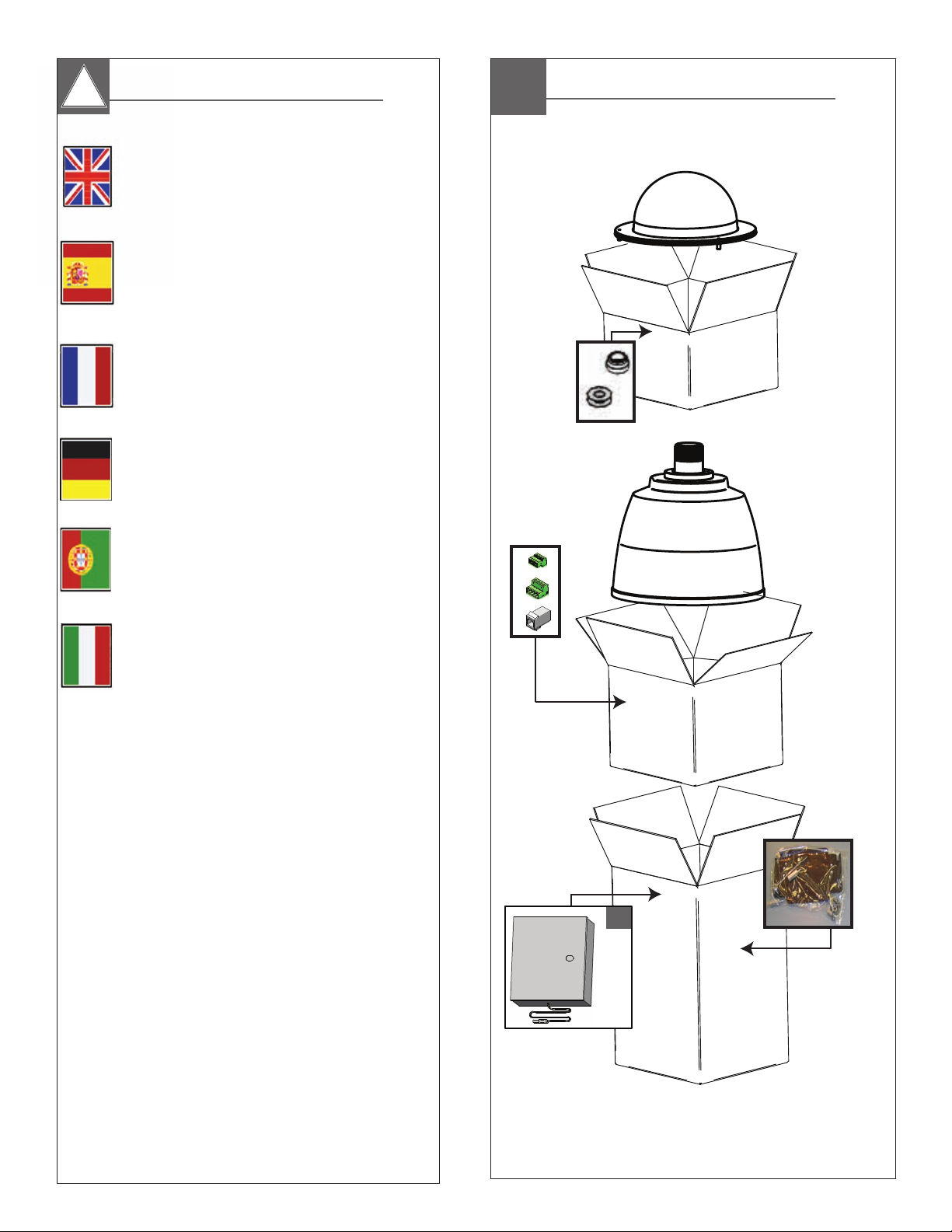
Contents of Box
*
* NOT included with E or 12V models
Page 5
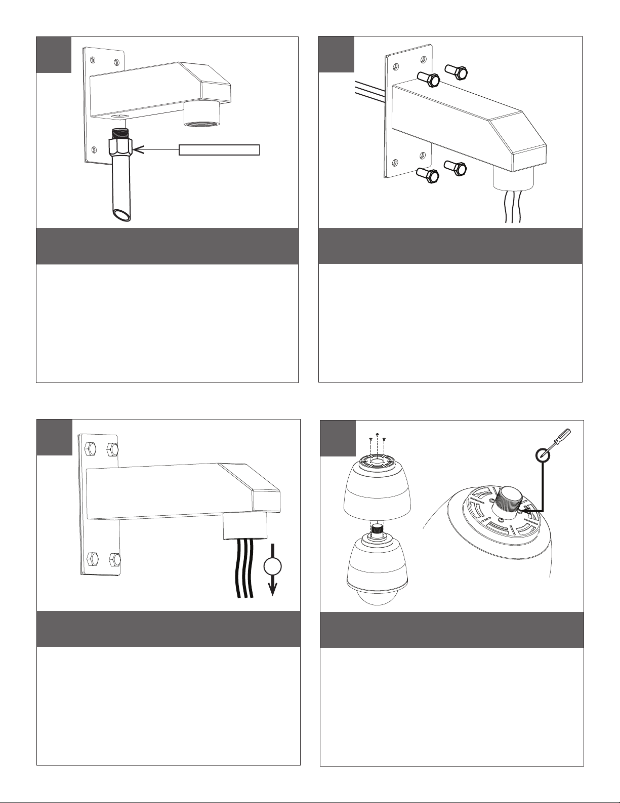
Wall mount bracket is designed for straight conduit. If
this tting is desired, install it rst.
• El soporte del montaje de la pared se diseña para el conducto recto.
Si se desea esta guarnición, instálela primero.
• La parenthèse de bâti de mur est conçue pour le conduit droit. Si cet
ajustage de précision est désiré, installez-le d'abord.
• Wandeinfassungshaltewinkel ist für gerades Rohr bestimmt. Wenn
diese Befestigung gewünscht wird, bringen Sie sie zuerst an.
• O suporte da montagem da parede é projetado para a canalização
reta. Se este encaixe é desejado, instale-o primeiramente.
• La staffa del supporto della parete è progettata per il condotto diritto.
Se questo montaggio è voluto, installilo in primo luogo.
1” Straight Conduit
1
2
Mount Sold Separately
Run connection wires through mount and attach to wall
with suitable mounting hardware.
• Funcione con los alambres de la conexión a través del montaje y
átelos a la pared con hardware de montaje conveniente.
• Courez les ls de raccordement par le bâti et les attachez au mur
avec le matériel de support approprié.
• Lassen Sie Anschlussdrähte durch Einfassung laufen und bringen
Sie zur Wand mit verwendbarer Montage-Hardware an.
• Funcione os da conexão através da montagem e una-os à parede
com ferragem de montagem apropriada.
• Faccia funzionare i legare del collegamento tramite il supporto ed
attacchi alla parete con i ssaggi di montaggio adatti.
3
Trim wires no longer than 5” outside mount.
• Alambres del ajuste no más que” montaje del exterior 5.
• Fils d'équilibre plus que » bâti de l'extérieur 5.
• Ordnungsdrähte nicht mehr als“ Einfassung der Außenseite 5.
• Fios da guarnição já não do que da” montagem parte externa 5.
• Legare della disposizione più che„ supporto della parte esterna 5.
4
X3 PLACES
5”
If required, install provided sunshield with
phillips screwdriver.
• Si procede, instale el sunshield proporcionado con
destornillador Phillips.
• S'il y a lieu, installez le sunshield fourni avec le tournevis Phillips.
• Wenn erforderlich bringen Sie zur Verfügung gestelltes sunshield
mit Kreuzkopfschraubenzieher an.
• Se requerido, instale o sunshield fornecido com chave de fenda Phillips.
• A richiesta, installi il sunshield fornito con il cacciavite "phillips".
Page 6
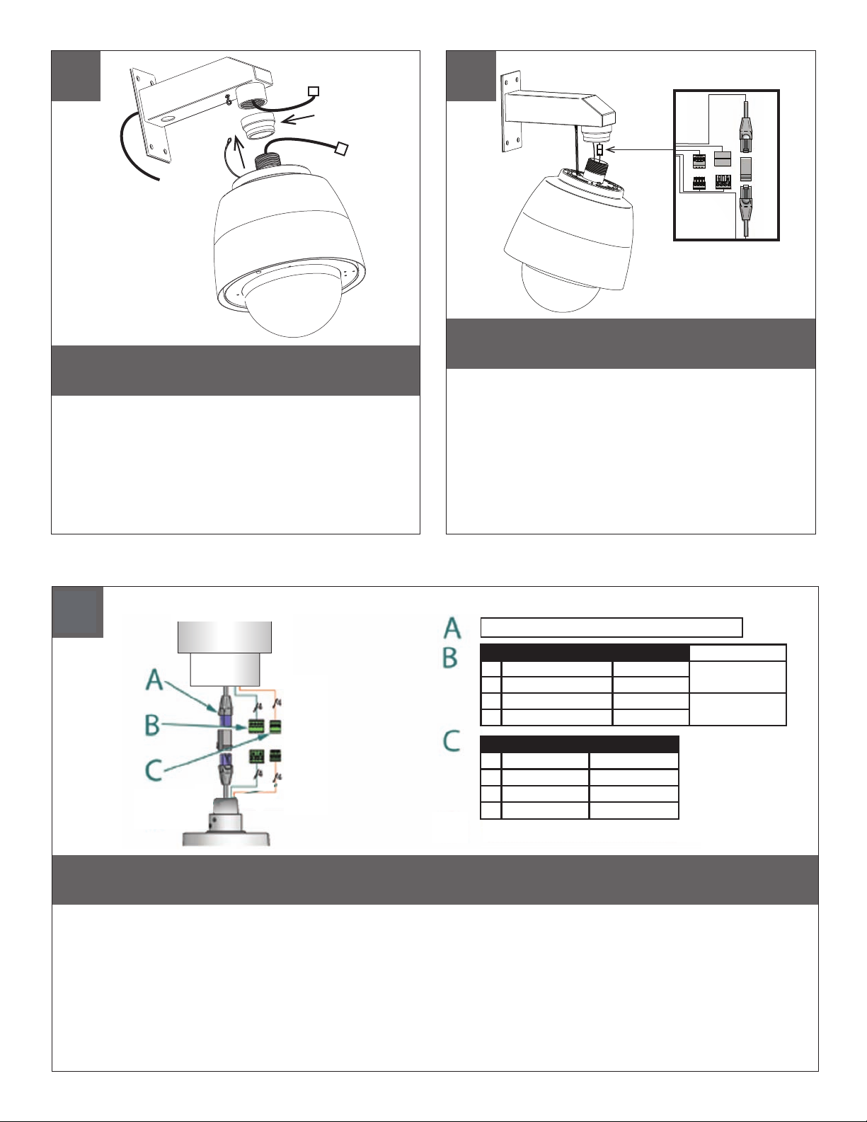
5
Gasket
Secure lanyard from dome housing to clip on
wall mount.
• Acollador seguro de la bóveda que contiene al clip en el
montaje de la pared.
• Lanière bloquée du dôme logeant à l'agrafe sur le bâti de mur.
• Sichere Abzuglinie von der Haube, die zum Klipp auf Wandeinfassung
unterbringt.
• Colhedor seguro da abóbada que abriga ao grampo na montagem
da parede.
• Cordicella sicura dalla cupola che alloggia alla clip sul supporto
della parete.
6
Complete all wiring connections.
• Termine todas las conexiones del cableado.
• Accomplissez tous les raccordements de câblage.
• Schließen Sie alle Verdrahtungsanschlüsse ab.
• Termine todas as conexões da ação.
• Completi tutti i collegamenti dei collegamenti.
7
RJ45
1
2
3
4
24VAC
Camera
Camera
Heater/Blower
Heater/Blower
Red
Orange
Yellow
Green
POWER
Max 25 Watts
Max 52 Watts
1/0
Alarm 1
1
2
Alarm 2
3
Alarm 3
4
Common
Make the appropriate male and female connections. Indoor model does not include pre-run cables.
• Haga las conexiones masculinas y femeninas apropiadas. El modelo de interior no incluye pre-funciona los cables.
• Établissez les rapports masculins et femelles appropriés. Le modèle d'intérieur n'inclut pas pré-courent des câbles.
• Stellen Sie die passenden männlichen und weiblichen Beziehungen her. Innenmodell schließt nicht vor-laufen lassen
Kabel ein.
• Faça as conexões masculinas e fêmeas apropriadas. O modelo indoor não inclui pre-funciona cabos.
Violet
Gray
Blue
White
• Faccia i collegamenti maschii e femminili adatti. Il modello dell'interno non include pre-fa funzionare i cavi.
Page 7

8
9
Total vA
consumed
5.5
10
20
30
40
50
60
70
80
Wire Gauge
,75201,0181,5162,514412610MM
600
960
121
54.9
43.0
27.4
21.3
17.1
14.3
12.2
10.3
300
225
130
112
90
75
64
55
182
91.4
68.6
39.6
34.1
27.4
22.9
19.5
16.8
480
358
225
179
143
119
102
85
292
146
109
68.6
54.6
43.6
36.2
31.1
25.9
- - -
800
243
571
174
350
106
285
86.9
228
69.5
190
57.9
163
49.7
140
42.7
ft
120
86
65
44
35
29
25
31
,5
22
36.5
27.1
19.8
13.4
10.6
9.4
8.8
7.6
400
m
180
141
90
70
56
47
40
34
1300
905
525
452
362
301
91.7
258
78.6
215
65.5
396
275
160
138
110
1440
830
720
576
480
411
340
-
438
252
219
175
146
125
103
2
AWG
On board power supply provides 12VDC power
for camera
• A bordo fuente de alimentación proporciona la energía
12VDC para la cámara
• À bord de l'alimentation d'énergie fournit la puissance
12VDC pour l'appareil-photo
• An Bord des Spg.Versorgungsteils stellt Energie 12VDC für
Kamera zur Verfügung
• A bordo da fonte de alimentação fornece o poder 12VDC
para a câmera
• A bordo dell'alimentazione elettrica fornisce il potere 12VDC
per la macchina fotografica
10
These are recommended maximum distances
for 24VAC with a 10% voltage drop.
• Éstos se recomiendan las distancias máximas para
24VAC con una caída de voltaje del 10%.
• Ceux-ci sont recommandés des distances maximum
pour 24VAC avec une chute de tension de 10%.
• Diese werden maximale Abstände für 24VAC mit
einem 10% Spannungsabfall empfohlen.
• Estes são recomendados distâncias máximas para
24VAC com uma queda de tensão de 10%.
• Questi sono suggeriti distanze massime per 24VAC con
una differenza de potenziale di 10%.
11
81-IN5481
Rotate housing assembly clockwise into wall
mount tting.
• Gire el montaje de la cubierta a la derecha en la guarnición del
montaje de la pared.
• Tournez le logement dans le sens des aiguilles d'une montre dans
l'ajustage de précision de bâti de mur.
• Drehen Sie Gehäuse nach rechts in Wandeinfassungsbefestigung.
• Gire o conjunto da carcaça no sentido horário no encaixe da
montagem da parede.
• Giri l'assemblea dell'alloggiamento in senso orario nel montaggio
del supporto della parete.
Refer to manual #81-IN5481 for camera
installation instructions.
• Reera a #81-IN5481 manual para las instrucciones de instalación
de la cámara.
• Référez-vous à #81-IN5481 manuel pour des instructions d'installation
d'appareil-photo.
• Beziehen Sie sich auf manuelles #81-IN5481 für
KameraMontagevorschriften.
• Rera #81-IN5481 manual para instruções de instalação da câmera.
• Riferisca a #81-IN5481 manuale per le istruzioni di installazione della
macchina fotograca.
Page 8

After Camera installation. Attach lanyard to the
trim ring assembly.
• Después de la instalación de la cámara. Ate el acollador al montaje
del anillo del ajuste.
• Après installation d'appareil-photo. Attachez la lanière à l'anneau
d'équilibre.
• Nach Kamerainstallation. Bringen Sie Abzuglinie zum OrdnungsRing an.
• Após a instalação da câmera. Una o colhedor ao conjunto do anel
da guarnição.
• Dopo l'installazione della macchina fotograca. Attacchi la cordicella
all'assemblea dell'anello della disposizione.
12
13
X3 PLACES
Fasten trim ring assembly to main housing
with a phillips screwdriver.
• Sujete el montaje del anillo del ajuste a la cubierta principal
con un destornillador Phillips.
• Attachez l'anneau d'équilibre au logement principal avec un
tournevis Phillips.
• Befestigen Sie OrdnungsRing am Hauptgehäuse mit einem
Kreuzkopfschraubenzieher.
• Prenda o conjunto do anel da guarnição à carcaça principal
com uma chave de fenda Phillips.
• Fissi l'assemblea dell'anello della disposizione ad alloggiamento
principale con un cacciavite "phillips".
Replacement Parts List
Part Number Description
N/S
RPRH713
Packet Assembly-Hardware-Fixed Housings
N/S
RP46PKH2012
Packet Assembly-Hardware-PTZ Housings
N/S
RPPKE1100
Packet Assembly-Electrical
N/S
RPBRRN2102
Camera Bracket Electronics Assembly-PTZ Housings
N/S
RPBRRH2110
Camera Bracket Electronics Assembly-fixed Housings
SILICON GASKET
RPVL4029 - STAINLESS SUNSHIELD
RPPC4075 - 16 PIN SEALED CONNECTOR
RPVL4025 - STAINLESS HOUSING MAIN ASSEMBLY
RP96RSORG23 - OUTER SILICONE O-RING 9”
RP96RSORG16 - INNER SILICONE O-RING 8”
RPVL4028 - STAINLESS UPPER CLAMP RING
RPDC3369NY - CLEAR REPLACEMENT NYLON DOME
RPVL4024 - STAINLESS LOWER TRIM RING
Page 9

C a m e r a M o u n t i n g I n s t r u c t i o n s
10-24-2012
!!
English
Español
Français
For all RHP, RHW, SSD and IGDW models, add
an additional ½” (13mm) spacer to heights
shown below.
Para todos los modelos de RHP, RHW, SSD y
IGDW, agregar un adicional de ½ "(13mm)
espaciador a las alturas se muestran a
continuación.
Pour tous les modèles RHP, RHW, SSD
et IGDW, ajouter un ½ supplémentaires
"(13mm) d'écartement à des hauteurs
indiquées ci-dessous.
NOTE:
Für alle RHP, RHW, SSD und IGDW Modelle,
fügen Sie einen zusätzlichen ½ "(13mm)
Abstandhalter zu Höhen unten gezeigt.
Deutsch
Para todos os modelos RHP, RHW, SSD e
IGDW, adicionar um adicional de ½ "(13mm)
espaçador para alturas abaixo.
Portuguese
Per tutti i modelli RHP, RHW, SSD e IGDW,
aggiungere un ulteriore ½ "(13mm)
spacer ad altezze indicate di seguito.
Italiano
(HARDWARE) (SPACING)
(1) (1) (88mm)
(1)
ACTi: ACM 8511
• Mounting holes
½”
1”
2”
(4-M3) (4) (88mm)
½”
1”
2”
Page 10

ARECONT: AV8185 / AV8365 / AV20185 / AV20365
• Mounting holes
(4-#8 x ¾”) (75mm)
(4)
(4)
AVIGILON: HD-Dome Series
• Mounting holes
(3-#8) (3) (100mm)
(3)
1”
1”
2”
1”
2”
Page 11

AXIS: 215
• Mounting holes
(4-#8) (4) (100mm)
(4)
AXIS: 233D
• Mounting holes
(4-#8) (4) (25mm)
(4)
1”
1”
1”
2”
BASLER: BIP2-1000C-DN / BIP2-1300C-DN / BIP-D1000C-DN / BIP-D1300C-DN
• Mounting holes
(3-#8) (3) (100mm)
(3)
1”
1”
2”
Page 12

CANON: VB-C60
• Mounting holes
(1)
CANON: VB-M40
• Mounting holes
(1)
(1)
(1)
(1)
(1)
(64mm)
(64mm)
½”
½”
2”
2”
CANON: VB-C300
• Mounting holes
(1)
(1)
(1)
(88mm)
½”
1”
2”
Page 13

ELMO: PTC 400C
• Mounting holes
(4-#8) (4) (100mm)
(4)
JVC: VN-V686BU / VN-V685U
• Mounting holes
(3-#8) (3) (38mm)
½”
½”
½”
1”
1”
2”
PANASONIC: BB-HCM580/581
• Mounting holes
x
(1)
(1)
(1)
(88mm)
½”
1”
2”
Page 14

PANASONIC: WV-CS580 Series
• Mounting holes
(4-#8)
PANASONIC: SC386
• Mounting holes
(4-#8) (4) (25mm)
(4)
(38mm)
½”
1”
1”
PANASONIC: WV-CS574
• Mounting holes
(4-#8) (4) (50mm)
(4)
2”
Page 15

PANASONIC: WV-CS954 / WV-NS954
• Mounting holes
(4-#8)
(4)
PANASONIC: WV-NS202 / WV-SC385 / WV-SC384
• Mounting holes
(4-#8) (4) (75mm)
(4)
(13mm)
½”
1”
2”
PIXORD: P-463
• Mounting holes
(3-#8) (3) (25mm)
(3)
1”
Page 16

SAMSUNG: SNP-6200, 3371,3302,3370,3301*
• Mounting holes
(4-#8) (4)
(4)
(* NOT FOR FDW/FDP MODELS )
SANYO: VCC-HD 5400
• Mounting holes
(2-#8) (2) (64mm)
½”
2”
SONY: EP / ER Series (520 / 550 / 580)
• Mounting holes
(4-#8) (4) (4) (38mm)
½”
1”
Page 17

SONY: RX Series (RX530 / RX550 / RX570)
• Mounting holes
(4-M3) (4)
SONY: SNC RH/RS Series (RH124 / RS44 / RS46)
• Mounting holes
(4-#8)
SONY: SNC-RZ25
• Mounting holes
(2-M3)
(2)
(4)
(1)
(1)
(1)
(25mm)
1”
(13mm)
½”
Page 18

SONY: SNC-RZ50
• Mounting holes
(2-M3)
(2)
TOSHIBA: IK-WB16A
• Mounting holes
(1)
(1)
(1)
(1)
(1)
(1)
(88mm)
(50mm)
½”
2”
1”
2”
TOSHIBA: IK-WB21A
• Mounting holes
(4-#8) (4) (75mm)
(4)
1”
2”
Page 19

VIDEO IQ: VIQ-CT / CID / CRD / HD-CRD
• Mounting holes
(4-M4x10) (4) (75mm)
1”
2”
Page 20

Product Registration/Warranty
Thank you for choosing Moog Videolarm. We value your patronage and are solely committed to providing you with the highest
quality products available and superior customer service.
Should a problem arise, rest assured that Moog Videolarm stands behind its products by offering impressive 3 Year and 5 Year warranties, depending on the product
purchased. See full warranty details at www.moogvideolarm.com/technical-support/warranty-plan/
Register Your Products Online
Please take a few moments to register your purchase via the Online Product Registration Form at:
www.moogvideolarm.com/technical-support/product-registration
Register your recent Moog Videolarm purchase and benet from the following:
• Simple and Trouble-Free RMA process
• Receive product updates, and special promotion
• Eliminate the need to archive original purchase documents:
Receipts, Purchase Orders, etc…
 Loading...