

Moog Song Producer Service Manual
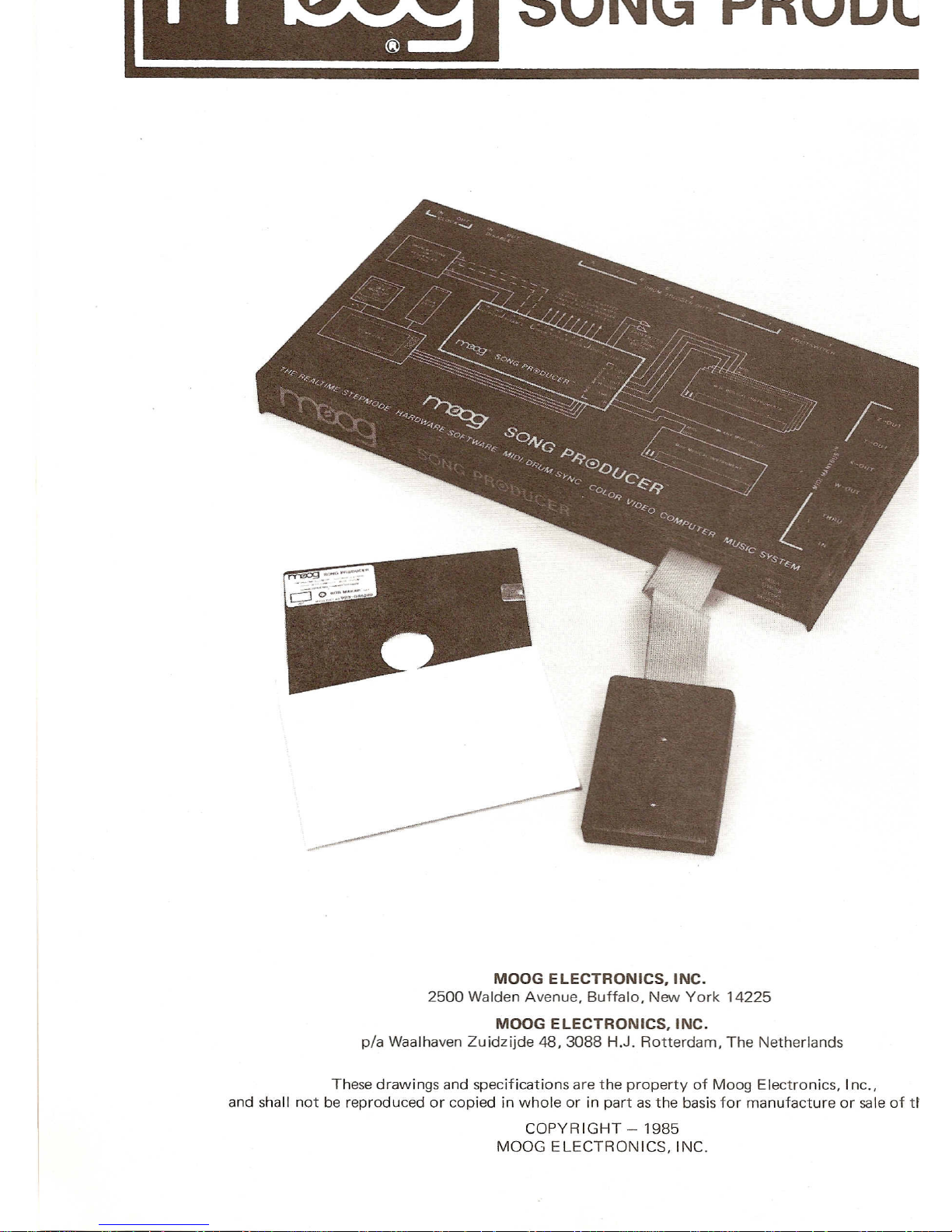
SONG PRODUCER
MOOG
ELECTRONICS. INC.
2500 Walden Avenue. Buffalo. New York 14225
MOOG
ELECTRONICS. INC.
pia Waalhaven Zuidzijde 48, 3088 H.J. Rotterdam, The Netherlands
These drawings and specifications are the property of Moog Electronics. Inc.•
a
nd shall not be reproduced or copied in whole or in part asthe basisfor manufacture or sale of the items.
COPYRIGHT - 1985
MOOG EL
ECTRONICS. INC.
www.bleeps-and-peeps.com
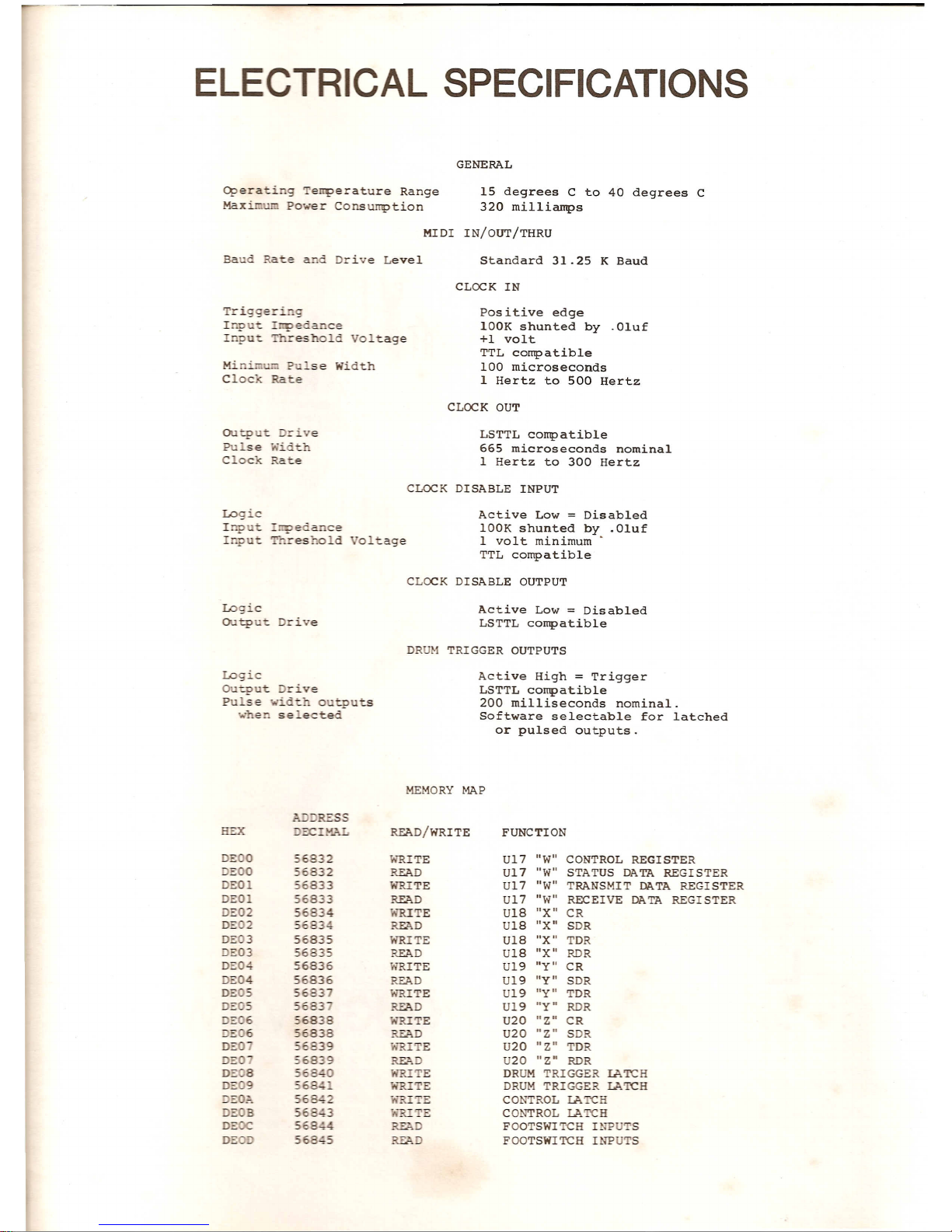
ELECTRICAL SPECIFICATIONS
O
perati.g Temperature Range
Max' Power Consurtption
15 degrees C to 40 degrees C
320 millia
rtps
Triggeri: 9
Inn
t
_lIDedance
Input Threshold Voltage
Positive edge
l
OOK shunted by .Oluf
+1 volt
TTL cortpatible
100 microseconds
1 Hertz to 500 Hertz
Mini.:::! se Width
Clod< Rate
outp
t
D::-
':ve
Pu se
~;i
'th
Clock Rate
LSTTL cortpatible
665 microseconds nominal
1
Hertz to 300 Hertz
Logic
Inp ~
Ir:;>eeance
I ut esr.old oltage
L
ogic
O
Utput Drive
Active Low=Disabled
l
OOK shunted by .Oluf
1
volt minimum'
TTL compatible
Active Low=Disabled
LSTTL cortpatible
Logic
Output rive
Pu se "dd-=."
0
tp
ts
••.•.he se_ected
A
ctive High=Trigger
LST
TL cortpatible
200 milliseconds nominal.
Software selectable for latched
or pulsed outputs
.
MEMORY MAP
;,
RESS
HEX
=:c
MAL
READ/WRITE
F
UNCTION
WRITE
U17
IlW
Il
CONTROL
RE
GISTER
READ
Ul7
IIW
ll
STATUS DATA
REGISTER
WRITE
U
17
"WI!
TRANSMIT
DATA
REGISTER
R
EAD
U17
"
WI!
RECEIVE DATA REGISTER
'f."RITE
U
18
"XII
CR
READ
U18
"X
II
S
DR
WRITE U18
"X"
TDR
READ
U18
IIX"
RDR
WRITE U19
"yll
CR
READ U19
"yl1
SDR
w"RITE
U19
"yll
TDR
~D U19
llyn
RDR
i'l'TITE
U20
"Zll
CR
READ U20
IIZI1
SDR
I'.XI
E U
20
"ZI1
TDR
REA
U20
HZ"
RDR
WRITE DRUM TRIGGER lATCH
WRI E DRUM
TRIGGER lATCH
'f.~':'E
CONTROL lATCH
'3L E
CONTROL lATCH
~D FOOTSWITCH INPU
S
Ri'7I. D
FOOTSWITCH INPUTS
www.bleeps-and-peeps.com
SONG PRODUCER
TESTIADJUSTMENT ITROUBLESHOOTING
Included on the master diskette is a
complete menu-driven program for testing
the Song Producer hardware module. All
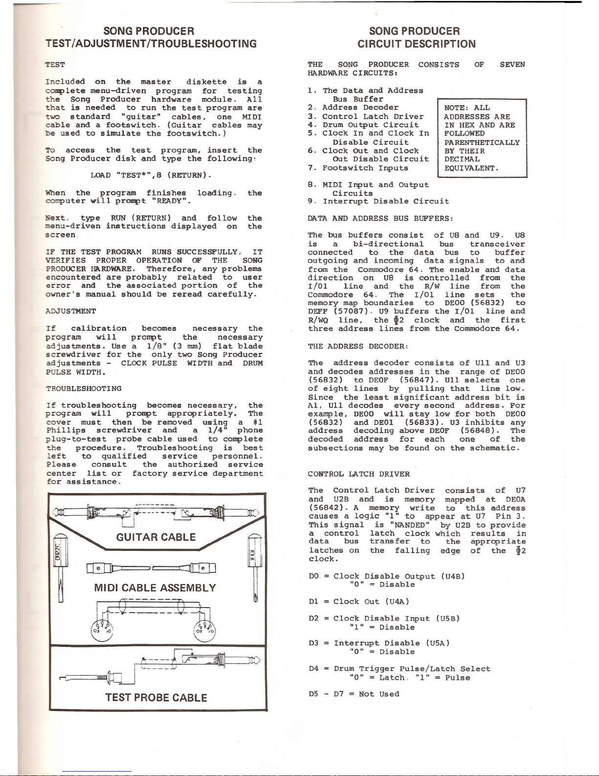
that is needed to run the test program are
~wo standard "guitar" cables, one MIDI
cable and a footswitch. (Guitar cables may
be used to simulate the footswitch.)
To access the test program, insert the
SOng Producer disk and type the following,
When the program finishes loading. the
computer will proMPt "READY".
N
ext. type RUN (RETURN) and follow the
enu-driven instructions displayed on the
screen
.
IF THE TEST PROGRAM RUNS SUCCESSFULLY. IT
VERIFIES PROPER OPERATION OF THE SONG
PRODUCER HARDWARE. Therefore, any problems
encountered are probably related to user
error and the associated portion of the
o
wner's manual should be reread carefully.
If calibration becomes necessary the
program will prompt the necessary
a
djustments. Use a 1/8" (3 mm) flat blade
screwdriver for the only two Song Producer
adjustments - CLOCK PULSE WIDTH and DRUM
P
ULSE WI DTH •
If troubleshooting becomes necessary, the
program will proMPt appropriately
. The
co
ver must then be removed using a #1
P
hillips screwdriver and a 1/4" phone
plug-to-test probe cable used to complete
the procedure. Troubleshooting is best
left to qualified service personnel.
Please consult the authorized service
center list
or factory service department
for assistance
.
lif-G~=-::-::
1L
it!)
0J ~
!':----C~==n"0
I '-"
.:..J
.-~-~~
TEST PROBE CABLE
SONG PRODUCER
C
IRCUIT DESCRIPTION
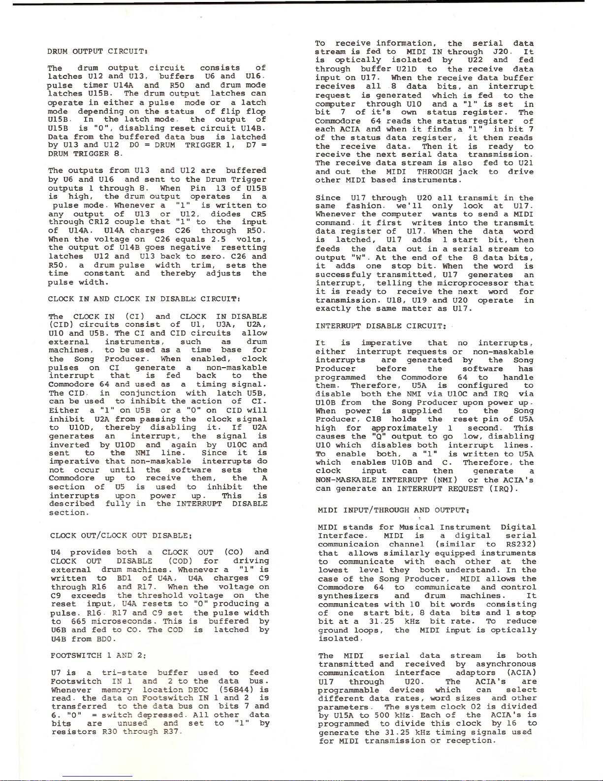
THE SONG PRODUCER CONSISTS
HARDWARE CIRCUITS
:
1. The Data and Address
Bus Buffer
2
. Address Decoder
3
. Control Latch Driver
4. Drum Output Circuit
5. Clock In and Clock In
Disable Circuit
6. Clock Out and Clock
OUt Disable Circuit
7. Fo
otswitch Inputs
NOTE
: ALL
ADDRESSES ARE
IN HEX AND ARE
FOLLO
WED
PARENTHETICALLY
BY THEIR
DECIMAL
EQUIVALENT.
8
. MIDI Input and Output
Circuits
9. Interrupt Disable Circuit
The bus buffers consist of U8 and U9. U8
is a bi-directional bus transceiver
connected to the data bus to buffer
outgoing and incoming data signals to and
from the Commodore 64. The enable and data
direction on U8 is controlled from the
1/01 line and the R/W line from the
Commodore 6
4. The 1/01 line sets the
memory map boundaries to DEOO
(56832) to
DEFF (5708
7). U9 buffers the 1/01 line and
R/WQ line, the
~2 clock and the first
three address lines from the Commodore 64.
The address decoder consists of UII and U3
and decodes addresses in the range of DEOO
(56832) to DEOF (568
47). UII selects one
of eight lines by pulling that line low.
Since the least significant address bit is
AI
, UII decodes every second address. For
example, DEOO will stay low for both DEOO
(56832) and DEO
I (56833). U3 inhibits any
address decoding above DEOF (568
48). The
decoded address for each one of the
subsections may be found on the schematic.
The Co
ntrol Latch Driver consists of U7
and U2B a
nd is memory mapped at DEOA
(56842). A me
mory write to this address
causes a logic "1" to appear at U7 Pin 3.
T
his signal is "NANDED" by U2B to provide
a control latch clock which results in
data bus transfer to the appropriate
latches on the falling edge of the
~2
clock.
DO
=
Clock Disable Output (U4B)
"0"
=
Dis able
Clock Disable Inp
ut (USB)
"1"=Disable
Interrupt Disable (USA)
"0"
=
Disable
Drum Trigger Pulse
/Latch Select
"
0"=Latch. "1"=Pulse
www.bleeps-and-peeps.com
The drum output circuit consists of
latches U12 and U13, buffers U6 and U16.
pulse timer U14A and R50 and drum mode
latches U15B.
The drum output latches can
operate in eit
her a pulse mode or a latch
mode depending on the status of flip flop
U15B. In the latch mode. the output of
U15B
is "0", disabling reset circuit U14B.
Data f
rom the buffered data bus is latched
by U13 and U12 D
O=DRUM TRIGGER 1. D7
=
DRUM TRIGGER 8.
The outputs from U13 and U12 are buffered
by U6 and U16 and sent to t
he Drum Trigger
outputs 1 through 8
. When Pin 13 of UlsB
is high. the drum output operates i
n a
pulse mode
. Whenever a "1" is written to
a
ny output of U13 or U12, diodes CRS
through CR12 coup
le that "1" to the input
of U1
4A. U14A charges C26 through RSO.
When the voltage on C26 equals 2.5 volts,
the output of U14B goes negative resetting
latc
hes U12 and U13 back to zero. C26 and
R50
. a drum pulse width trim, sets the
time constant and
thereby adjusts the
pulse
width.
The CLOCK IN (CI) and CLOCK IN DISABLE
(CID) circuits consist
of U1, U3A. U2A,
UIO and USB.
The CI and CID circuits allow
external instruments, such as drum
machi
nes. to be used as a time base for
the So
ng Producer. When enabled, clock
pu
lses on CI generate a non-maskable
i
nterrupt that is fed back to the
Commodore 6
4 and used as a timing signal.
The CID
.. in conjunction with latch USB.
can be used t
o inhibit the action of CI.
Either a "1" on USB or a "0" on CID will
inhibit U2A from passing the clock signal
to UIOD, thereby disabling it. If U2A
gene
rates an interrupt, the signal is
inverted by UIOD and again by U10C and
se
nt to the NMI line. Since it is
impe
rative that non-maskable interrupts do
no
t occur until the software sets the
Commodore
up to receive them, the A
section of US is used to inhibit the
interrupt
s upon power up. This is
described fully in the INTERRUPT DISABLE
section
.
U4
provides both a CLOCK OUT (CO) and
CLOCK OUT DISABLE (COD) for driving
e
xternal drum machines. Whenever a "1" is
written to BDI of U4A, U4A charges C9
throug
h R16 and R17. When the voltage on
C9 e
xceeds the threshold voltage on the
reset input, U4A resets to "0" producing a
pulse. R16. R17 and C9 set the pulse width
to 665 microseconds. This is buffered by
U6B and fed to CO. The COD is latched by
U4
B from BDO.
U
7 is a tri-state buffer used
F
ootswitch IN 1 and 2 to the
Whenever memory location DEOC
read. the data on Footswitch IN
transferred to the data bus on
6.
"0"
=
switch depressed. All
bits are unused and set
resistors R30 through R37.
to feed
da
ta bus.
(5
6844) is
1 and 2 is
bits 7 and
othe
r data
to
"1" by
To receive information. the serial data
stream
is fed to MIDI IN through J20. It
is optically isolated by U22 and fed
t
hrough buffer U21D to the receive data
i
nput on U17. When the receive data buffer
rece
ives all 8 data bits. an interrupt
request
is generated which is fed to the
computer through UIO and a
"1" is set in
bit 7 of it
's own status register. The
Commodore 64 reads the status register of
each
ACIA and when it finds a "1" in bit 7
of th~ status data register, it then reads
the rece
ive data. Then it is ready to
recei
ve the next serial data transmission.
The receive data stream is also fed to U21
and out the
MIDI THROUGH jack to drive
other MIDI based instruments.
Since U17 through U20 all transmit in the
same fash
ion. we'll only look at U17.
Whenever the computer wants to send a MIDI
command
. it first writes into the transmit
data register of U17
. When the data word
is latched. U17 adds 1 start bit, then
feeds the data out in a serial stream to
output
"W". At the end of the 8 data bits.
it adds one stop bit. When the word is
successfu
ly transmitted, U17 generates an
interrupt. telling the microprocessor that
it is ready to
receive the next word for
transmission
. U18, U19 and U20 operate in
exactly the same matter as U17.
It is imperative that no interrupts,
either interrupt requests or non-maskable
interrupts are generated by the Song
Producer before the sof
tware has
programmed the Commodore 6
4 to handle
them
. Therefore, USA is configured to
disable both
the NMI via UIOC and IRQ via
UIOB from t
he Song Producer upon power up.
When power is supplied to the Song
Producer, Cl8 holds the reset pin of USA
high fo
r approximately 1 second. This
causes the "Q" output to go low, disabling
U
IO which disables both interrupt lines.
To enable both. a "1" is written to USA
which enables UIOB and C. Therefore, the
clock input can then generate a
NON-MASKABLE INTERRUPT (NMI) or the ACIA's
can generate an INTERRUPT REQUEST (IRQ
).
MIDI stands for Musical Instrument Digital
Interface. MIDI is a digital serial
communicaion c
hannel (similar to RS232)
that allo
ws similarly equipped instruments
to communicate
with each other at the
lo
west level they both understand. In the
case of the So
ng Producer, MIDI allows the
C
ommodore 64 to communicate and control
s
ynthesizers and drum machines. It
communic
ates with 10 bit words consisting
of one star
t bit, 8 data bits and 1 stop
bit at a 31.25 kHz bit rate. To reduce
ground
loops, the MIDI input is optically
isolated.
The MIDI serial data stream is both
transmitted
and received by asynchronous
com
munication interface adaptors (ACIA)
U17 through U20. The ACIA's are
programmable devices which can select
different data rates, word sizes and other
parameters. The system clock 02 is divided
by U15A to 500 kHz. Each of the ACIA's is
programmed to divide this clock by 16 to
g
enerate the 31.25 kHz timing signals us~d
for MIDI transmission or reception.
www.bleeps-and-peeps.com
 Loading...