

Page 1
Developer’s
Guide
Class 5 & Later SmartMotor
Technology with
TM
Page 2

Copyright Notice
©2001–2018, Moog Inc., Animatics.
Moog Animatics SmartMotor™ Developer's Guide, Rev. L, PN:SC80100003-002.
This manual, as well as the software described in it, is furnished under license and may be
used or copied only in accordance with the terms of such license. The content of this manual is
furnished for informational use only, is subject to change without notice and should not be
construed as a commitment by Moog Inc., Animatics. Moog Inc., Animatics assumes no
responsibility or liability for any errors or inaccuracies that may appear herein.
Except as permitted by such license, no part of this publication may be reproduced, stored in a
retrieval system or transmitted, in any form or by any means, electronic, mechanical,
recording, or otherwise, without the prior written permission of Moog Inc., Animatics.
The programs and code samples in this manual are provided for example purposes only. It is
the user's responsibility to decide if a particular code sample or program applies to the
application being developed and to adjust the values to fit that application.
Moog Animatics and the Moog Animatics logo, SmartMotor and the SmartMotor logo,
Combitronic and the Combitronic logo, and SMI are all trademarks of Moog Inc., Animatics.
Other trademarks are the property of their respective owners.
Please let us know if you find any errors or omissions in this manual so that we can improve it
for future readers. Such notifications should contain the words "Developer's Guide" in the
subject line and be sent by e-mail to: animatics_marcom@moog.com. Thank you in advance
for your contribution.
Contact Us:
Americas - West
Moog Animatics
2581 Leghorn Street
Mountain View, CA 94043
USA
Tel: 1 650-960-4215 Tel: 1 610-328-4000 x3999
Support: 1 888-356-0357
Website: www.animatics.com
Email: animatics_sales@moog.com
Americas - East
Moog Animatics
750 West Sproul Road
Springfield, PA 19064
USA
Fax: 1 610-605-6216
Page 3

Table Of Contents
Introduction 27
Overview 28
Combitronic Support 28
Communication Lockup Wizard 30
Safety Information 30
Safety Symbols 30
Other Safety Considerations 31
Motor Sizing 31
Environmental Considerations 31
Machine Safety 31
Documentation and Training 32
Additional Equipment and Considerations 33
Safety Information Resources 33
Additional Documents 34
Related Guides 34
Other Documents 34
Additional Resources 35
Part 1: Programming the SmartMotor 36
Beginning Programming 47
Setting the Motor Firmware Version 48
Setting the Default Firmware Version 48
Checking the Default Firmware Version 49
Opening the SMIWindow (Program Editor) 49
Understanding the Program Requirements 50
Creating a "Hello World" Program 51
Entering the Program in the SMI Editor 51
Adding Comments to the Code 52
Checking the Program Syntax 52
Saving the Program 52
Downloading a Program to the SmartMotor 52
Syntax Checking, Compiling and Downloading the Program 53
Additional Notes on Downloaded Programs 53
Running a Downloaded Program 54
Moog Animatics SmartMotor™ Developer's Guide,Rev. L
Page 3 of 909
Page 4

Using the Program Download Window 55
Using the Terminal Window and Run Program Button 55
Using the RUN Command in the Terminal Window 55
Creating a Simple Motion Program 56
SMISoftware Features 57
Introduction 58
Menu Bar 58
Toolbar 59
Configuration Window 61
Terminal Window 63
Initiating Motion from the Terminal Window 65
Information Window 65
Program Editor 66
Motor View 68
SMI Trace Functions 70
Monitor Window 73
Serial Data Analyzer 75
Chart View 76
Chart View Example 77
Macros 80
Tuner 82
SMIOptions 86
SMIHelp 87
Context-Sensitive Help Using F1 87
Context-Sensitive Help Using the Mouse 87
Help Buttons 87
Hover Help 87
Table of Contents 87
Projects 88
SmartMotor Playground 89
Opening the SmartMotor Playground 90
Moving the Motor 91
Communication Details 93
Introduction 95
Connecting to a Host 96
Daisy Chaining Multiple D-Style SmartMotors over RS-232 97
ADDR=formula 98
Moog Animatics SmartMotor™ Developer's Guide,Rev. L
Page 4 of 909
Page 5

SLEEP, SLEEP1 99
WAKE, WAKE1 99
ECHO, ECHO1 100
ECHO_OFF, ECHO_OFF1 100
Serial Commands 101
OCHN(type,channel,parity,bit rate,stop bits,data bits,mode,timeout) 101
CCHN(type,channel) 102
BAUDrate, BAUD(channel)=formula 102
PRINT(), PRINT1() 102
SILENT, SILENT1 103
TALK, TALK1 103
a=CHN(channel) 103
a=ADDR 104
Communicating over RS-485 104
Using Data Mode 104
CAN Communications 107
CADDR=formula 107
CBAUD=formula 107
=CAN, =CAN(arg) 107
CANCTL(function,value) 107
SDORD(...) 108
SDOWR(...) 108
NMT 109
RB(2,4), x=B(2,4) 109
Exceptions to NMT, SDORD and SDOWR Commands 109
I/O Device CAN Bus Master 110
Combitronic Communications 111
Combitronic Features 112
Other Combitronic Benefits 112
Program Loops with Combitronic 112
Global Combitronic Transmissions 113
Simplify Machine Support 113
Combitronic with RS-232 Interface 113
Other CANProtocols 115
CANopen - CAN Bus Protocol 115
DeviceNet - CAN Bus Protocol 115
I²C Communications (D-Style Motors) 115
Moog Animatics SmartMotor™ Developer's Guide,Rev. L
Page 5 of 909
Page 6

OCHN(IIC,1,N,baud,1,8,D) 117
CCHN(IIC,1) 117
PRINT1(arg1,arg2, … ,arg_n) 117
RGETCHR1, Var=GETCHR1 117
RLEN1, Var=LEN1 117
Motion Details 118
Introduction 120
Motion Command Quick Reference 121
Basic Motion Commands 122
Target Commands 122
PT=formula 122
PRT=formula 123
ADT=formula 123
AT=formula 123
DT=formula 123
VT=formula 123
Motion Mode Commands 124
MP 124
MV 124
MT 124
Torque Commands 125
TS=formula 125
T=formula 125
Brake Commands 125
BRKRLS 125
BRKENG 125
BRKSRV 126
BRKTRJ 126
Brake Command Examples 126
EOBK(IO) 127
MTB 127
Index Capture Commands 128
Other Motion Commands 129
G 129
S 129
X 130
O=formula 130
Moog Animatics SmartMotor™ Developer's Guide,Rev. L
Page 6 of 909
Page 7

OSH=formula 130
OFF 130
Commutation Modes 131
MDT 131
MDE 131
MDS 131
MDC 132
MDB 132
MINV(0), MINV(1) 132
Modes of Operation 133
Torque Mode 133
Torque Mode Example 133
Dynamically Change from Velocity Mode to Torque Mode 133
Velocity Mode 134
Constant Velocity Example 134
Change Commanded Speed and Acceleration 134
Absolute (Position) Mode 135
Absolute Move Example 135
Two Moves with Delay Example 135
Change Speed and Acceleration Example 135
Shift Point of Origin Example 136
Relative Position Mode 136
Relative Mode Example 136
Follow Mode with Ratio (Electronic Gearing) 137
Electronic Gearing and Camming over CANopen 137
Electronic Gearing Commands 138
SRC(enc_src) 138
MFR 138
MSR 138
MF0 138
MS0 138
MFMUL=formula, MFDIV=formula 138
MFA(distance[,m/s]) 139
MFD(distance[,m/s]) 139
MFSLEW(distance[,m/s]) 139
Follow Internal Clock Source Example 139
Follow Incoming Encoder Signal With Ramps Example 140
Moog Animatics SmartMotor™ Developer's Guide,Rev. L
Page 7 of 909
Page 8

Electronic Line Shaft 142
ENCD(in_out) 142
Spooling and Winding Overview 143
Relative Position, Auto-Traverse Spool Winding 143
MFSDC(distance,mode) 144
Dedicated, Absolute Position, Winding Traverse Commands 146
MFSDC(distance,2) 147
MFLTP=formula 147
MFHTP=formula 147
MFCTP(arg1,arg2) 147
MFL(distance[,m/s]) 148
MFH(distance[,m/s]) 148
ECS(counts) 148
Single Trajectory Example Program 150
Chevron Wrap Example 150
Other Traverse Mode Notes 152
Traverse Mode Status Bits 153
CamMode (Electronic Camming) 153
Electronic Camming Details 156
Understanding the Inputs 156
Should I choose Source Counts or Intermediate Counts? 157
Should I choose Variable or Fixed cam? 157
Electronic Camming Notes and Best Practices 159
Examples 161
Electronic Gearing and Camming over CANopen 161
Electronic Camming Commands 162
CTE(table) 162
CTA(points,seglen[,location]) 162
CTW(pos[,seglen][,user]) 162
MCE(arg) 163
MCW(table,point) 163
RCP 164
RCTT 164
MC 164
MCMUL=formula 164
MCDIV=formula 164
O(arg)=formula 164
Moog Animatics SmartMotor™ Developer's Guide,Rev. L
Page 8 of 909
Page 9

OSH(arg)=formula 164
Cam Example Program 165
Mode Switch Example 168
Position Counters 170
Modulo Position 171
Modulo Position Commands 171
Dual Trajectories 172
Commands That Read Trajectory Information 174
Dual Trajectory Example Program 175
Synchronized Motion 175
Synchronized-Target Commands 175
PTS(), PRTS() 175
VTS=formula 176
ADTS=formula, ATS=formula, DTS=formula 177
PTSS(), PRTSS() 177
A Note About PTS and PTSS 177
Other Synchronized-Motion Commands 178
GS 178
TSWAIT 179
Program Flow Details 181
Introduction 182
Flow Commands 182
RUN 183
RUN? 183
GOTO#, GOTO(label), C# 183
GOSUB#, GOSUB(label), RETURN 184
IF, ENDIF 184
ELSE, ELSEIF 185
WHILE, LOOP 186
SWITCH, CASE, DEFAULT, BREAK, ENDS 186
TWAIT 187
WAIT=formula 187
STACK 187
END 188
Program Flow Examples 189
IF, ELSEIF, ELSE, ENDIF Examples 189
WHILE, LOOPExamples 189
Moog Animatics SmartMotor™ Developer's Guide,Rev. L
Page 9 of 909
Page 10

GOTO(), GOSUB() Examples 190
SWITCH, CASE, BREAK, ENDS Examples 191
Interrupt Programming 192
ITR(), ITRE, ITRD, EITR(), DITR(), RETURNI 192
TMR(timer,time) 194
Variables and Math 195
Introduction 196
Variable Commands 196
EPTR=formula 196
VST(variable,number) 196
VLD(variable,number) 197
Math Expressions 197
Math Operations 197
Logical Operations 197
Integer Operations 197
Floating Point Functions 197
Math OperationDetails and Examples 198
Array Variables 198
Array Variable Examples 199
Error and Fault Handling Details 200
Motion and Motor Faults 201
Overview 201
Drive Stage Indications and Faults 201
Fault Bits 201
Error Handling 202
Example Fault-Handler Code 202
PAUSE 203
RESUME 203
Limits and Fault Handling 204
Position Error Limits 204
dE/dt Limits 204
Velocity Limits 204
Hardware Limits 204
Software Limits 205
Fault Handling 205
Monitoring the SmartMotor Status 206
System Status 208
Moog Animatics SmartMotor™ Developer's Guide,Rev. L
Page 10 of 909
Page 11

Introduction 209
Retrieving and Manipulating Status Words/Bits 209
System and Motor Status Bits 209
Reset Error Flags 211
System Status Examples 211
Timer Status Bits 212
Interrupt Status Bits 212
I/O Status 213
User Status Bits 213
Multiple Trajectory Support Status Bits 214
Cam Status Bits 215
Interpolation Status Bits 216
Motion Mode Status 216
RMODE, RMODE(arg) 216
I/OControl Details 217
I/O Port Hardware 218
I/O Connections Example (D-Style Motors) 219
I/O Voltage Spikes 219
Discrete Input and Output Commands 220
Discrete Input Commands 220
Discrete Output Commands 220
Output Condition and Fault Status Commands 221
Output Condition Commands 221
Output Fault Status Reports 221
General-Use Input Configuration 221
Multiple I/OFunctions Example 222
Analog Functions of I/O Ports 223
5 Volt Push-Pull I/O Analog Functions (D-Style Motors) 223
24 Volt I/O Analog Functions (D-Style AD1 Option Motors, M-Style Motors) 223
Special Functions of I/OPorts 224
Class 5 D-Style Motors: Special Functions of I/O Ports 225
I/O Ports 0 and 1 – External Encoder Function Commands 225
I/O Ports 2 and 3 – Travel Limit Inputs 225
I/O Ports 4 and 5 – Communications 225
I/O Port 6 – Go Command, Encoder Index Capture Input 226
Class 5 M-Style Motors: Special Functions of I/O Ports 227
COM Port Pins 4, 5, 6, and 8 – A-quad-B or Step-and-Direction Modes 227
Moog Animatics SmartMotor™ Developer's Guide,Rev. L
Page 11 of 909
Page 12

I/O Ports 2 and 3 – Travel Limit Inputs 227
I/O Port 5 – Encoder Index Capture Input 227
I/O Port 6 – Go Command 228
Class 6 M-Style Motors: Special Functions of I/O Ports 229
COM Port Pins 4, 5, 6, and 8 – A-quad-B or Step-and-Direction Modes 229
I/O Ports 2 and 3 – Travel Limit Inputs 229
I/O Port 4 and 5 – Encoder Index Capture Input 229
I/O Port 6 – Go Command 230
I/O Brake Output Commands 230
I²C Expansion (D-Style Motors) 230
Tuning and PIDControl 231
Introduction 232
Understanding the PID Control 232
Tuning the PID Control 233
Using F 233
Setting KP 234
Setting KD 234
Setting KI and KL 234
Setting EL=formula 235
Other PID Tuning Parameters 235
KG=formula 235
KV=formula 235
KA=formula 236
Current Limit Control 237
AMPS=formula 237
Part 2: SmartMotor Command Reference 238
(Single Space Character) 240
a...z 241
aa...zz 241
aaa...zzz 241
Ra...Rz 241
Raa...Rzz 241
Raaa...Rzzz 241
ab[index]=formula 245
Rab[index] 245
ABS(value) 248
Moog Animatics SmartMotor™ Developer's Guide,Rev. L
Page 12 of 909
Page 13

RABS(value) 248
AC 250
RAC 250
ACOS(value) 253
RACOS(value) 253
ADDR=formula 255
RADDR 255
ADT=formula 257
ADTS=formula 259
af[index]=formula 261
Raf[index] 261
Ai(arg) 264
Aij(arg) 266
Aj(arg) 268
Aji(arg) 270
al[index]=formula 272
Ral[index] 272
AMPS=formula 275
RAMPS 275
ASIN(value) 278
RASIN(value) 278
AT=formula 280
RAT 280
ATAN(value) 282
RATAN(value) 282
ATOF(index) 284
RATOF(index) 284
ATS=formula 286
aw[index]=formula 288
Raw[index] 288
B(word,bit) 291
RB(word,bit) 291
Ba 295
RBa 295
BAUD(channel)=formula 297
RBAUD(channel) 297
Be 299
Moog Animatics SmartMotor™ Developer's Guide,Rev. L
Page 13 of 909
Page 14

RBe 299
Bh 301
RBh 301
Bi(enc) 304
RBi(enc) 304
Bj(enc) 307
RBj(enc) 307
Bk 310
RBk 310
Bl 311
RBl 311
Bls 313
RBls 313
Bm 315
RBm 315
Bms 317
RBms 317
Bo 319
RBo 319
Bp 320
RBp 320
Bps 322
RBps 322
Br 324
RBr 324
BREAK 326
BRKENG 328
BRKRLS 330
BRKSRV 332
BRKTRJ 334
Brs 336
RBrs 336
Bs 338
RBs 338
Bt 340
RBt 340
Bv 342
Moog Animatics SmartMotor™ Developer's Guide,Rev. L
Page 14 of 909
Page 15

RBv 342
Bw 344
RBw 344
Bx(enc) 346
RBx(enc) 346
C{number} 348
CADDR=formula 350
RCADDR 350
CAN, CAN(arg) 352
RCAN, RCAN(arg) 352
CANCTL(function,value) 354
CASE formula 355
CBAUD=formula 358
RCBAUD 358
CCHN(type,channel) 360
CHN(channel) 361
RCHN(channel) 361
CLK=formula 363
RCLK 363
COMCTL(function,value) 364
COS(value) 366
RCOS(value) 366
CP 368
RCP 368
CTA(points,seglen[,location]) 370
CTE(table) 372
CTR(enc) 374
RCTR(enc) 374
CTT 376
RCTT 376
CTW(pos[,seglen][,user]) 377
DEA 380
RDEA 380
DEFAULT 382
DEL=formula 384
RDEL 384
DELM(arg) 386
Moog Animatics SmartMotor™ Developer's Guide,Rev. L
Page 15 of 909
Page 16

DFS(value) 387
RDFS(value) 387
DITR(int) 388
DT=formula 390
RDT 390
DTS=formula 392
EA 394
REA 394
ECHO 396
ECHO0 398
ECHO1 399
ECHO_OFF 400
ECHO_OFF0 401
ECHO_OFF1 402
ECS(counts) 403
EIGN(...) 405
EILN 408
EILP 410
EIRE 412
EIRI 414
EISM(6) 416
EITR(int) 417
EL=formula 419
REL 419
ELSE 421
ELSEIF formula 423
ENC0 425
ENC1 426
ENCCTL(function,value) 428
ENCD(in_out) 430
END 431
ENDIF 433
ENDS 435
EOBK(IO) 437
EOIDX(number) 439
EPTR=formula 440
REPTR 440
Moog Animatics SmartMotor™ Developer's Guide,Rev. L
Page 16 of 909
Page 17

ERRC 441
RERRC 441
ERRW 443
RERRW 443
ETH(arg) 444
RETH(arg) 444
ETHCTL(function,value) 445
F 446
FABS(value) 448
RFABS(value) 448
FSA(cause,action) 450
FSQRT(value) 452
RFSQRT(value) 452
FW 454
RFW 454
G 456
GETCHR 459
RGETCHR 459
GETCHR1 461
RGETCHR1 461
GOSUB(label) 463
GOTO(label) 465
GS 467
HEX(index) 469
RHEX(index) 469
I(enc) 471
RI(enc) 471
IDENT=formula 473
RIDENT 473
IF formula 475
IN(...) 478
RIN(...) 478
INA(...) 481
RINA(...) 481
IPCTL(function,"string") 484
ITR(Int#,StatusWord,Bit#,BitState,Label#) 486
ITRD 489
Moog Animatics SmartMotor™ Developer's Guide,Rev. L
Page 17 of 909
Page 18

ITRE 491
J(enc) 493
RJ(enc) 493
KA=formula 495
RKA 495
KD=formula 497
RKD 497
KG=formula 499
RKG 499
KI=formula 501
RKI 501
KII=formula 503
RKII 503
KL=formula 504
RKL 504
KP=formula 506
RKP 506
KPI=formula 508
RKPI 508
KS=formula 509
RKS 509
KV=formula 511
RKV 511
LEN 513
RLEN 513
LEN1 514
RLEN1 514
LFS(value) 516
RLFS(value) 516
LOAD 518
LOCKP 521
LOOP 522
MC 524
MCDIV=formula 527
RMCDIV 527
MCE(arg) 528
MCMUL=formula 530
Moog Animatics SmartMotor™ Developer's Guide,Rev. L
Page 18 of 909
Page 19

RMCMUL 530
MCW(table,point) 532
MDB 534
MDC 536
MDE 538
MDH 540
MDHV 542
MDS 544
MDT 546
MF0 548
MFA(distance[,m/s]) 550
MFCTP(arg1,arg2) 553
MFD(distance[,m/s]) 555
MFDIV=formula 558
MFH(distance[,m/s]) 560
MFHTP=formula 562
MFL(distance[,m/s]) 564
MFLTP=formula 566
MFMUL=formula 568
MFR 570
MFSDC(distance,mode) 573
MFSLEW(distance[,m/s]) 575
MINV(arg) 577
MODE 579
RMODE 579
MP 582
MS0 585
MSR 587
MT 589
MTB 591
MV 593
NMT 595
N/A 595
O=formula, O(trj#)=formula 597
OC(...) 599
ROC(...) 599
OCHN(...) 601
Moog Animatics SmartMotor™ Developer's Guide,Rev. L
Page 19 of 909
Page 20

OF(...) 603
ROF(...) 603
OFF 605
OR(value) 607
OS(...) 609
OSH=formula, OSH(trj#)=formula 611
OUT(...)=formula 613
PA 615
RPA 615
PAUSE 617
PC, PC(axis) 619
RPC, RPC(axis) 619
PI 622
RPI 622
PID# 623
PMA 626
RPMA 626
PML=formula 628
RPML 628
PMT=formula 630
RPMT 630
PRA 632
RPRA 632
PRC 635
RPRC 635
PRINT(...) 638
PRINT0(...) 642
PRINT1(...) 646
PRINT8(...) 649
PRT=formula 652
RPRT 652
PRTS(...) 654
PRTSS(...) 656
PT=formula 658
RPT 658
PTS(...) 660
PTSD 663
Moog Animatics SmartMotor™ Developer's Guide,Rev. L
Page 20 of 909
Page 21

RPTSD 663
PTSS(...) 664
PTST 666
RPTST 666
RANDOM=formula 667
RRANDOM 667
RCKS 669
RES 670
RRES 670
RESUME 672
RETURN 674
RETURNI 676
RSP 678
RSP1 680
RSP5 681
RUN 682
RUN? 684
S (as command) 686
SADDR# 688
SAMP 690
RSAMP 690
SDORD(...) 692
RSDORD 692
SDOWR(...) 694
SILENT 696
SILENT1 698
SIN(value) 700
RSIN(value) 700
SLD 702
SLE 704
SLEEP 706
SLEEP1 708
SLM(mode) 710
RSLM 710
SLN=formula 712
RSLN 712
SLP=formula 714
Moog Animatics SmartMotor™ Developer's Guide,Rev. L
Page 21 of 909
Page 22

RSLP 714
SNAME("string") 716
SP2 717
RSP2 717
SQRT(value) 718
RSQRT(value) 718
SRC(enc_src) 720
STACK 722
STDOUT=formula 725
SWITCH formula 727
T=formula 730
Read/write 730
TALK 732
TALK1 734
TAN(value) 736
RTAN(value) 736
TEMP, TEMP(arg) 738
RTEMP, RTEMP(arg) 738
TH=formula 740
RTH 740
TMR(timer,time) 743
RTMR(timer) 743
TRQ 745
RTRQ 745
TS=formula 747
RTS 747
TSWAIT 749
TWAIT(gen#) 750
UIA 752
RUIA 752
UJA 754
RUJA 754
UO(...)=formula 756
UP 758
UPLOAD 760
UR(...) 762
US(...) 764
Moog Animatics SmartMotor™ Developer's Guide,Rev. L
Page 22 of 909
Page 23

USB(arg) 766
RUSB 766
VA 768
RVA 768
VAC(arg) 771
VC 776
RVC 776
VL=formula 778
RVL 778
VLD(variable,number) 780
VST(variable,number) 784
VT=formula 788
RVT 788
VTS=formula 791
W(word) 793
RW(word) 793
WAIT=formula 795
WAKE 797
WAKE1 799
WHILE formula 801
X 804
Z 806
Z(word,bit) 808
Za 810
Ze 811
Zh 812
Zl 813
Zls 814
Zr 815
Zrs 816
Zs 817
ZS 818
Zv 821
Zw 822
Part 3: Example SmartMotor Programs 823
Move Back and Forth 824
Moog Animatics SmartMotor™ Developer's Guide,Rev. L
Page 23 of 909
Page 24

Move Back and Forth with Watch 824
Home Against a Hard Stop (Basic) 825
Home Against a Hard Stop (Advanced) 825
Home Against a Hard Stop (Two Motors) 826
Home to Index Using Different Modes 828
Maintain Velocity During Analog Drift 829
Long-Term Storage of Variables 830
Find Errors and Print Them 830
Change Speed on Digital Input 831
Pulse Output on a Given Position 831
Stop Motion if Voltage Drops 832
Camming - Variable Cam Example 833
Camming - Fixed Cam with Input Variables 834
Camming - Demo XYCircle 836
Chevron Traverse & Takeup 838
CAN Bus - Timed SDOPoll 840
CAN Bus - I/OBlock with PDOPoll 841
CAN Bus - Time Sync Follow Encoder 844
Text Replacement in an SMI Program 852
Appendix 854
Motion Command Quick Reference 856
Array Variable Memory Map 858
ASCIICharacter Set 860
Binary Data 861
Command Error Codes 864
Decoding the Error 864
Finding the Error Source 865
Glossary 866
Math Operators 873
Moment of Inertia 874
Matching Motor to Load 874
Improving the Moment of Inertia Ratio 874
RCAN, RCHN and RMODEStatus 875
RCAN Status Decoder 875
RCHN Status Decoder 875
Clearing Serial Port Errors 876
Moog Animatics SmartMotor™ Developer's Guide,Rev. L
Page 24 of 909
Page 25

RMODE Status Decoder 876
Mode Status Example 876
Scale Factor Calculation 877
Sample Rates 877
PID Sample Rate Command 877
Encoder Resolution and the RES Parameter 877
Native Velocity and Acceleration Units 878
Velocity Calculations 878
Acceleration Calculations 878
Status Words 879
Status Word: 0Primary Fault/Status Indicator 879
Status Word: 1Index Registration and Software Travel Limits 880
Status Word: 2Communications, Program and Memory 880
Status Word: 3PID State, Brake, Move Generation Indicators 881
Status Word: 4 Interrupt Timers 881
Status Word: 5 Interrupt Status Indicators 882
Status Word: 6 Drive Modes 882
Status Word 7: Multiple Trajectory Support 883
Status Word 8: Cam Support 884
Status Word 10: RxPDO Arrival Notification 884
Status Word 12: User Bits Word 0 885
Status Word 13: User Bits Word 1 885
Status Word: 16 On Board Local I/O Status: D-Style Motor 886
Status Word: 16 On Board Local I/O Status: M-Style Motor 886
Status Word: 17 Expanded I/O Status: D-Style AD1 Motor 887
Torque Curves 888
Understanding Torque Curves 888
Peak Torque 888
Continuous Torque 888
Ambient Temperature Effects on Torque Curves and Motor Response: 889
Supply Voltage Effects on Torque Curves and Motor Response: 889
Example 1: Rotary Application 890
Example 2: Linear Application 890
Dyno Test Data vs. the Derated Torque Curve 890
Proper Sizing and Loading of the SmartMotor 891
Moog Animatics SmartMotor™ Developer's Guide,Rev. L
Page 25 of 909
Page 26

Commands Listed Alphabetically 893
Commands Listed by Function 900
Communications Control 901
Data Conversion 902
EEPROM (Nonvolatile Memory) 902
I/OControl 902
Math Function 903
Motion Control 903
Program Access 906
Program Execution and Flow Control 906
Reset Commands 907
System 907
Variables 908
Moog Animatics SmartMotor™ Developer's Guide,Rev. L
Page 26 of 909
Page 27

Introduction
Introduction
Introduction
This chapter provides introductory reference material.
Overview 28
Combitronic Support 28
Communication Lockup Wizard 30
Safety Information 30
Additional Documents 34
Additional Resources 35
Moog Animatics SmartMotor™ Developer's Guide,Rev. L
Page 27 of 909
Page 28

Introduction
Introduction: Overview
Overview
The SmartMotor™ Developer's Guide is designed to be used by system developers and
programmers when developing applications for the SmartMotor. Before using the
SmartMotor™ Developer's Guide, it is strongly recommended that you first read the
SmartMotor™ Installation & Startup Guide for your SmartMotor, which describes how to
install and start up the SmartMotor, and test initial communications with the motor. After that,
use this guide to learn about advanced SmartMotor features, how to develop SmartMotor
applications, and the details of each command.
Part One of this guide provides information on basic to advanced programming, along with
related information on key SMIsoftware features, communications, motion control, program
flow control, error and fault handling, and more.
Part Two of this guide lists all the SmartMotor commands in alphabetical order. Each
command is described in detail. Code snippets and examples are provided where applicable.
These are shown in a Courier font. Comments are included and separated with a single
quotation mark as they would be in your own programs.
NOTE: The programs and code samples in this manual are provided for example
purposes only. It is the user's responsibility to decide if a particular code sample or
program applies to the application being developed and to adjust the values to fit
that application.
Also, where appropriate, a Related Commands section is included, which is located at the end
of the command page. It is designed to guide you to other commands that offer similar
functionality, and ensure you are aware of every programming option the SmartMotor
provides to address your specific application requirements.
Part Three of this guide provides a library of useful example SmartMotor programs. These can
be used as "how to" examples for using a particular SmartMotor feature or solving a particular
application problem, or as starting points for your application.
NOTE: The programs and code samples in this manual are provided for example
purposes only. It is the user's responsibility to decide if a particular code sample or
program applies to the application being developed and to adjust the values to fit
that application.
The Appendix of this guide contains additional topics such as an array map, ASCII character
set, command error codes, and other information that is useful to have handy during
application development.
A quick-reference command list is also included at the end of this guide.
Combitronic Support
A large number of the commands provide Combitronic™ support. Combitronic is a protocol
that operates over a standard "CAN" (Controller Area Network) interface. It may coexist with
either CANopen or DeviceNet protocols at the same time. Unlike these common protocols,
however, Combitronic requires no single dedicated master to operate. Each Integrated Servo
connected to the same network communicates on an equal footing, sharing all information,
and therefore, sharing all processing resources. For more details on Combitronic features,
see Combitronic Communications on page 111, and also see the overview on the Moog
Animatics website at:
http://www.animatics.com/supports/knowledge-base/smartmotorkb/130.html.
Moog Animatics SmartMotor™ Developer's Guide,Rev. L
Page 28 of 909
Page 29
Introduction
Introduction: Combitronic Support
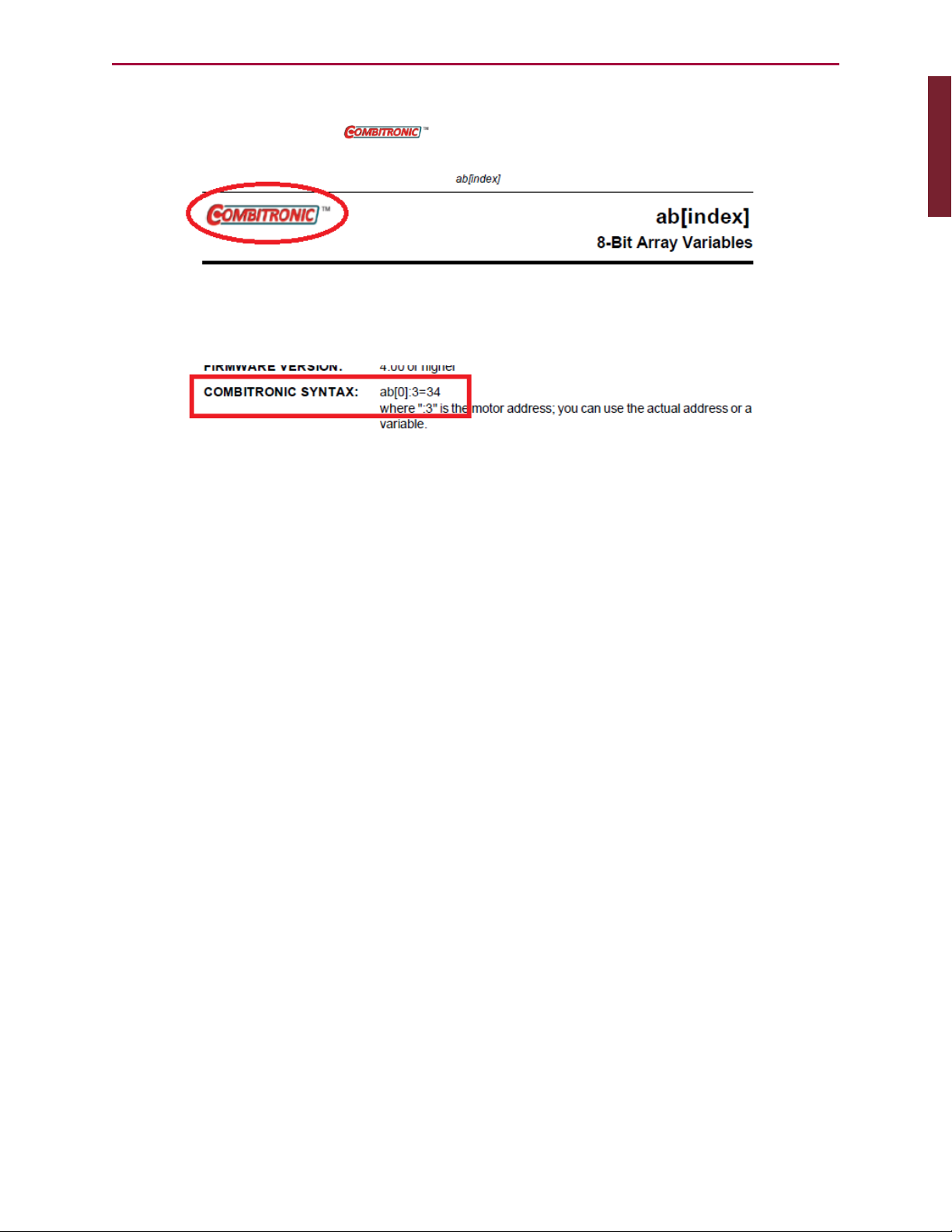
For applicable commands, a table row titled "COMBITRONIC:" provides the Combitronic
command syntax for addressing a specific SmartMotor in the network. Those commands also
display the Combitronic logo ( ) at the top of their reference pages.
Combitronic Logo Location
COMBITRONIC: Table Row
Moog Animatics SmartMotor™ Developer's Guide,Rev. L
Page 29 of 909
Page 30
Introduction
Introduction: Communication Lockup Wizard
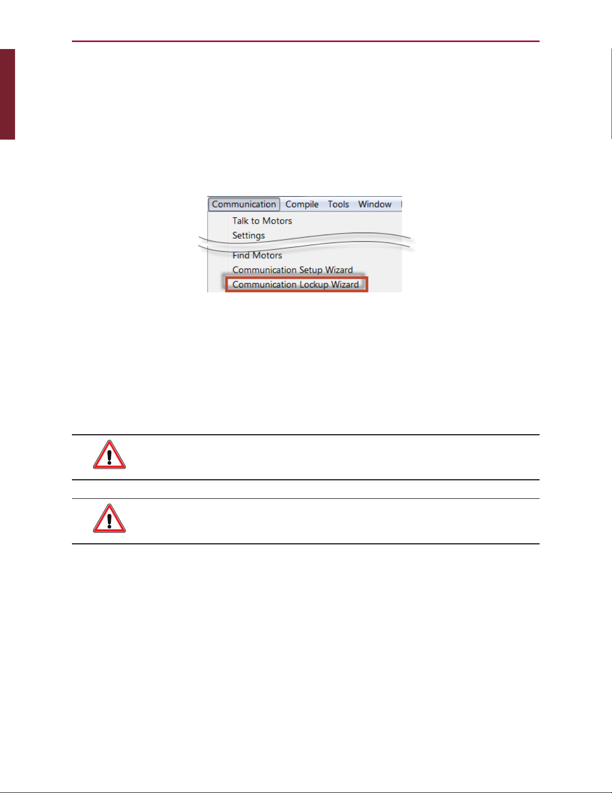
Communication Lockup Wizard
Improper use of some commands, like Z and OCHN, can lock you out of the motor and
prevent further communication. If you are unable to communicate with the SmartMotor, you
may be able to recover communications using the Communication Lockup Wizard, which is on
the SMI software Communications menu (see the following figure). This tool sends an "E"
character to the motor at startup, which prevents the motor from running its program. For
more details on the Communication Lockup Wizard, see the SMI software online help, which is
accessed by pressing the F1 key or selecting Help from the SMI software main menu.
Communication Menu - Communication Lockup Wizard
Safety Information
This section describes the safety symbols and other safety information.
Safety Symbols
The manual may use one or more of the following safety symbols:
WARNING: This symbol indicates a potentially nonlethal mechanical hazard,
where failure to follow the instructions could result in serious injury to the
operator or major damage to the equipment.
CAUTION: This symbol indicates a potentially minor hazard, where failure to
follow the instructions could result in slight injury to the operator or minor
damage to the equipment.
NOTE: Notes are used to emphasize non-safety concepts or related information.
Moog Animatics SmartMotor™ Developer's Guide,Rev. L
Page 30 of 909
Page 31

Introduction
Introduction: Other Safety Considerations
Other Safety Considerations
The Moog Animatics SmartMotors are supplied as components that are intended for use in an
automated machine or system. As such, it is beyond the scope of this manual to attempt to
cover all the safety standards and considerations that are part of the overall machine/system
design and manufacturing safety. Therefore, the following information is intended to be used
only as a general guideline for the machine/system designer.
It is the responsibility of the machine/system designer to perform a thorough "Risk
Assessment" and to ensure that the machine/system and its safeguards comply with the
safety standards specified by the governing authority (for example, ISO, OSHA, UL, etc.) for
the locale where the machine is being installed and operated. For more details, see Machine
Safety on page 31.
Motor Sizing
It is the responsibility of the machine/system designer to select SmartMotors that are
properly sized for the specific application. Undersized motors may: perform poorly, cause
excessive downtime or cause unsafe operating conditions by not being able to handle the
loads placed on them. The System Best Practices document, which is available on the Moog
Animatics website, contains information and equations that can be used for selecting the
appropriate motor for the application.
Replacement motors must have the same specifications and firmware version used in the
approved and validated system. Specification changes or firmware upgrades require the
approval of the system designer and may require another Risk Assessment.
Environmental Considerations
It is the responsibility of the machine/system designer to evaluate the intended operating
environment for dust, high-humidity or presence of water (for example, a food-processing
environment that requires water or steam wash down of equipment), corrosives or chemicals
that may come in contact with the machine, etc. Moog Animatics manufactures specialized
IP-rated motors for operating in extreme conditions. For details, see the Moog Animatics
Product Catalog.
Machine Safety
In order to protect personnel from any safety hazards in the machine or system, the
machine/system builder must perform a "Risk Assessment", which is often based on the ISO
13849 standard. The design/implementation of barriers, emergency stop (E-stop)
mechanisms and other safeguards will be driven by the Risk Assessment and the safety
standards specified by the governing authority (for example, ISO, OSHA, UL, etc.) for the
locale where the machine is being installed and operated. The methodology and details of
such an assessment are beyond the scope of this manual. However, there are various sources
of Risk Assessment information available in print and on the internet.
NOTE: The following list is an example of items that would be evaluated when
performing the Risk Assessment. Additional items may be required. The safeguards
must ensure the safety of all personnel who may come in contact with or be in the
vicinity of the machine.
In general, the machine/system safeguards must:
l
Provide a barrier to prevent unauthorized entry or access to the machine or system. The
barrier must be designed so that personnel cannot reach into any identified danger
Moog Animatics SmartMotor™ Developer's Guide,Rev. L
Page 31 of 909
Page 32

Introduction
Introduction: Documentation and Training
zones.
l
Position the control panel so that it is outside the barrier area but located for an
unrestricted view of the moving mechanism. The control panel must include an E-stop
mechanism. Buttons that start the machine must be protected from accidental
activation.
l
Provide E-stop mechanisms located at the control panel and at other points around the
perimeter of the barrier that will stop all machine movement when tripped.
l
Provide appropriate sensors and interlocks on gates or other points of entry into the
protected zone that will stop all machine movement when tripped.
l
Ensure that if a portable control/programming device is supplied (for example, a handheld operator/programmer pendant), the device is equipped with an E-stop mechanism.
NOTE: A portable operation/programming device requires many additional
system design considerations and safeguards beyond those listed in this
section. For details, see the safety standards specified by the governing
authority (for example, ISO, OSHA, UL, etc.) for the locale where the
machine is being installed and operated.
l
Prevent contact with moving mechanisms (for example, arms, gears, belts, pulleys,
tooling, etc.).
l
Prevent contact with a part that is thrown from the machine tooling or other parthandling equipment.
l
Prevent contact with any electrical, hydraulic, pneumatic, thermal, chemical or other
hazards that may be present at the machine.
l
Prevent unauthorized access to wiring and power-supply cabinets, electrical boxes, etc.
l
Provide a proper control system, program logic and error checking to ensure the safety
of all personnel and equipment (for example, to prevent a run-away condition). The
control system must be designed so that it does not automatically restart the
machine/system after a power failure.
l
Prevent unauthorized access or changes to the control system or software.
Documentation and Training
It is the responsibility of the machine/system designer to provide documentation on safety,
operation, maintenance and programming, along with training for all machine operators,
maintenance technicians, programmers, and other personnel who may have access to the
machine. This documentation must include proper lockout/tagout procedures for maintenance
and programming operations.
It is the responsibility of the operating company to ensure that:
l
All operators, maintenance technicians, programmers and other personnel are tested
and qualified before acquiring access to the machine or system.
l
The above personnel perform their assigned functions in a responsible and safe manner
to comply with the procedures in the supplied documentation and the company safety
practices.
l
The equipment is maintained as described in the documentation and training supplied by
the machine/system designer.
Moog Animatics SmartMotor™ Developer's Guide,Rev. L
Page 32 of 909
Page 33

Introduction
Introduction: Additional Equipment and Considerations
Additional Equipment and Considerations
The Risk Assessment and the operating company's standard safety policies will dictate the
need for additional equipment. In general, it is the responsibility of the operating company to
ensure that:
l
Unauthorized access to the machine is prevented at all times.
l
The personnel are supplied with the proper equipment for the environment and their job
functions, which may include: safety glasses, hearing protection, safety footwear,
smocks or aprons, gloves, hard hats and other protective gear.
l
The work area is equipped with proper safety equipment such as first aid equipment,
fire suppression equipment, emergency eye wash and full-body wash stations, etc.
l
There are no modifications made to the machine or system without proper engineering
evaluation for design, safety, reliability, etc., and a Risk Assessment.
Safety Information Resources
Additional SmartMotor safety information can be found on the Moog Animatics website; open
the file "109_Controls, Warnings and Cautions.pdf" located at:
http://www.animatics.com/support/moog-animatics-catalog.html
OSHA standards information can be found at:
https://www.osha.gov/law-regs.html
ANSI-RIA robotic safety information can be found at:
http://www.robotics.org/robotic-content.cfm/Robotics/Safety-Compliance/id/23
UL standards information can be found at:
http://ulstandards.ul.com/standards-catalog/
ISOstandards information can be found at:
http://www.iso.org/iso/home/standards.htm
EUstandards information can be found at:
http://ec.europa.eu/growth/single-market/european-standards/harmonisedstandards/index_en.htm
Moog Animatics SmartMotor™ Developer's Guide,Rev. L
Page 33 of 909
Page 34

Introduction
Introduction: Additional Documents
Additional Documents
The Moog Animatics website contains additional documents that are related to the information
in this manual. Please refer to the following list.
Related Guides
l
SmartMotor™ Installation & Startup Guide (select the guide for your SmartMotor)
http://www.animatics.com/install-guides
l
SmartMotor™ Fieldbus Guide (select the guide for your SmartMotor and fieldbus
protocol)
http://www.animatics.com/fieldbus-manuals
Other Documents
l
SmartMotor™ Product Certificate of Conformance
http://www.animatics.com/download/Declaration of Conformity.pdf
l
SmartMotor™ ULCertification
http://www.animatics.com/download/MA_UL_online_listing.pdf
l
SmartMotor Developer's Worksheet
(interactive tools to assist developer: Scale Factor Calculator, Status Words, CAN Port
Status, Serial Port Status, RMODE Decoder and Syntax Error Codes)
http://www.animatics.com/tools
l
Moog Animatics Product Catalog
http://www.animatics.com/support/moog-animatics-catalog.html
Moog Animatics SmartMotor™ Developer's Guide,Rev. L
Page 34 of 909
Page 35

Additional Resources
Additional Resources
The Moog Animatics website contains useful resources such as product information,
documentation, product support and more. Please refer to the following addresses:
l
General company information:
http://www.animatics.com
l
Product information:
http://www.animatics.com/products.html
l
Product support (Downloads, How To videos, Forums, Knowledge Base, and FAQs):
http://www.animatics.com/support.html
l
Sales and distributor information:
http://www.animatics.com/sales-offices.html
l
Application ideas (including videos and sample programs):
http://www.animatics.com/applications.html
Moog Animatics SmartMotor™ Developer's Guide,Rev. L
Page 35 of 909
Page 36

Part 1: Programming the SmartMotor
Part 1: Programming the SmartMotor
Part 1 of this guide provides information on programming, SMIsoftware features,
communications, variables, error and fault handling, I/Ocontrol, and other details required
for system and application development.
Beginning Programming 47
Setting the Motor Firmware Version 48
Setting the Default Firmware Version 48
Checking the Default Firmware Version 49
Opening the SMIWindow (Program Editor) 49
Understanding the Program Requirements 50
Creating a "Hello World" Program 51
Entering the Program in the SMI Editor 51
Adding Comments to the Code 52
Checking the Program Syntax 52
Saving the Program 52
Downloading a Program to the SmartMotor 52
Syntax Checking, Compiling and Downloading the Program 53
Additional Notes on Downloaded Programs 53
Running a Downloaded Program 54
Using the Program Download Window 55
Using the Terminal Window and Run Program Button 55
Using the RUN Command in the Terminal Window 55
Creating a Simple Motion Program 56
SMISoftware Features 57
Introduction 58
Menu Bar 58
Toolbar 59
Configuration Window 61
Terminal Window 63
Initiating Motion from the Terminal Window 65
Information Window 65
Moog Animatics SmartMotor™ Developer's Guide,Rev. L
Page 36 of 909
Page 37

Part 1: Programming the SmartMotor
Program Editor 66
Motor View 68
SMI Trace Functions 70
Monitor Window 73
Serial Data Analyzer 75
Chart View 76
Chart View Example 77
Macros 80
Tuner 82
SMIOptions 86
SMIHelp 87
Context-Sensitive Help Using F1 87
Context-Sensitive Help Using the Mouse 87
Help Buttons 87
Hover Help 87
Table of Contents 87
Projects 88
SmartMotor Playground 89
Opening the SmartMotor Playground 90
Moving the Motor 91
Communication Details 93
Introduction 95
Connecting to a Host 96
Daisy Chaining Multiple D-Style SmartMotors over RS-232 97
ADDR=formula 98
SLEEP, SLEEP1 99
WAKE, WAKE1 99
ECHO, ECHO1 100
ECHO_OFF, ECHO_OFF1 100
Serial Commands 101
OCHN(type,channel,parity,bit rate,stop bits,data bits,mode,timeout) 101
CCHN(type,channel) 102
BAUDrate, BAUD(channel)=formula 102
PRINT(), PRINT1() 102
Moog Animatics SmartMotor™ Developer's Guide,Rev. L
Page 37 of 909
Page 38

Part 1: Programming the SmartMotor
SILENT, SILENT1 103
TALK, TALK1 103
a=CHN(channel) 103
a=ADDR 104
Communicating over RS-485 104
Using Data Mode 104
CAN Communications 107
CADDR=formula 107
CBAUD=formula 107
=CAN, =CAN(arg) 107
CANCTL(function,value) 107
SDORD(...) 108
SDOWR(...) 108
NMT 109
RB(2,4), x=B(2,4) 109
Exceptions to NMT, SDORD and SDOWR Commands 109
I/O Device CAN Bus Master 110
Combitronic Communications 111
Combitronic Features 112
Other Combitronic Benefits 112
Program Loops with Combitronic 112
Global Combitronic Transmissions 113
Simplify Machine Support 113
Combitronic with RS-232 Interface 113
Other CANProtocols 115
CANopen - CAN Bus Protocol 115
DeviceNet - CAN Bus Protocol 115
I²C Communications (D-Style Motors) 115
OCHN(IIC,1,N,baud,1,8,D) 117
CCHN(IIC,1) 117
PRINT1(arg1,arg2, … ,arg_n) 117
RGETCHR1, Var=GETCHR1 117
RLEN1, Var=LEN1 117
Moog Animatics SmartMotor™ Developer's Guide,Rev. L
Page 38 of 909
Page 39

Part 1: Programming the SmartMotor
Motion Details 118
Introduction 120
Motion Command Quick Reference 121
Basic Motion Commands 122
Target Commands 122
PT=formula 122
PRT=formula 123
ADT=formula 123
AT=formula 123
DT=formula 123
VT=formula 123
Motion Mode Commands 124
MP 124
MV 124
MT 124
Torque Commands 125
TS=formula 125
T=formula 125
Brake Commands 125
BRKRLS 125
BRKENG 125
BRKSRV 126
BRKTRJ 126
Brake Command Examples 126
EOBK(IO) 127
MTB 127
Index Capture Commands 128
Other Motion Commands 129
G 129
S 129
X 130
O=formula 130
OSH=formula 130
OFF 130
Moog Animatics SmartMotor™ Developer's Guide,Rev. L
Page 39 of 909
Page 40

Part 1: Programming the SmartMotor
Commutation Modes 131
MDT 131
MDE 131
MDS 131
MDC 132
MDB 132
MINV(0), MINV(1) 132
Modes of Operation 133
Torque Mode 133
Torque Mode Example 133
Dynamically Change from Velocity Mode to Torque Mode 133
Velocity Mode 134
Constant Velocity Example 134
Change Commanded Speed and Acceleration 134
Absolute (Position) Mode 135
Absolute Move Example 135
Two Moves with Delay Example 135
Change Speed and Acceleration Example 135
Shift Point of Origin Example 136
Relative Position Mode 136
Relative Mode Example 136
Follow Mode with Ratio (Electronic Gearing) 137
Electronic Gearing and Camming over CANopen 137
Electronic Gearing Commands 138
SRC(enc_src) 138
MFR 138
MSR 138
MF0 138
MS0 138
MFMUL=formula, MFDIV=formula 138
MFA(distance[,m/s]) 139
MFD(distance[,m/s]) 139
MFSLEW(distance[,m/s]) 139
Follow Internal Clock Source Example 139
Moog Animatics SmartMotor™ Developer's Guide,Rev. L
Page 40 of 909
Page 41

Part 1: Programming the SmartMotor
Follow Incoming Encoder Signal With Ramps Example 140
Electronic Line Shaft 142
ENCD(in_out) 142
Spooling and Winding Overview 143
Relative Position, Auto-Traverse Spool Winding 143
MFSDC(distance,mode) 144
Dedicated, Absolute Position, Winding Traverse Commands 146
MFSDC(distance,2) 147
MFLTP=formula 147
MFHTP=formula 147
MFCTP(arg1,arg2) 147
MFL(distance[,m/s]) 148
MFH(distance[,m/s]) 148
ECS(counts) 148
Single Trajectory Example Program 150
Chevron Wrap Example 150
Other Traverse Mode Notes 152
Traverse Mode Status Bits 153
CamMode (Electronic Camming) 153
Electronic Camming Details 156
Understanding the Inputs 156
Should I choose Source Counts or Intermediate Counts? 157
Should I choose Variable or Fixed cam? 157
Electronic Camming Notes and Best Practices 159
Examples 161
Electronic Gearing and Camming over CANopen 161
Electronic Camming Commands 162
CTE(table) 162
CTA(points,seglen[,location]) 162
CTW(pos[,seglen][,user]) 162
MCE(arg) 163
MCW(table,point) 163
RCP 164
RCTT 164
Moog Animatics SmartMotor™ Developer's Guide,Rev. L
Page 41 of 909
Page 42

Part 1: Programming the SmartMotor
MC 164
MCMUL=formula 164
MCDIV=formula 164
O(arg)=formula 164
OSH(arg)=formula 164
Cam Example Program 165
Mode Switch Example 168
Position Counters 170
Modulo Position 171
Modulo Position Commands 171
Dual Trajectories 172
Commands That Read Trajectory Information 174
Dual Trajectory Example Program 175
Synchronized Motion 175
Synchronized-Target Commands 175
PTS(), PRTS() 175
VTS=formula 176
ADTS=formula, ATS=formula, DTS=formula 177
PTSS(), PRTSS() 177
A Note About PTS and PTSS 177
Other Synchronized-Motion Commands 178
GS 178
TSWAIT 179
Program Flow Details 181
Introduction 182
Flow Commands 182
RUN 183
RUN? 183
GOTO#, GOTO(label), C# 183
GOSUB#, GOSUB(label), RETURN 184
IF, ENDIF 184
ELSE, ELSEIF 185
WHILE, LOOP 186
SWITCH, CASE, DEFAULT, BREAK, ENDS 186
Moog Animatics SmartMotor™ Developer's Guide,Rev. L
Page 42 of 909
Page 43

Part 1: Programming the SmartMotor
TWAIT 187
WAIT=formula 187
STACK 187
END 188
Program Flow Examples 189
IF, ELSEIF, ELSE, ENDIF Examples 189
WHILE, LOOPExamples 189
GOTO(), GOSUB() Examples 190
SWITCH, CASE, BREAK, ENDS Examples 191
Interrupt Programming 192
ITR(), ITRE, ITRD, EITR(), DITR(), RETURNI 192
TMR(timer,time) 194
Variables and Math 195
Introduction 196
Variable Commands 196
EPTR=formula 196
VST(variable,number) 196
VLD(variable,number) 197
Math Expressions 197
Math Operations 197
Logical Operations 197
Integer Operations 197
Floating Point Functions 197
Math OperationDetails and Examples 198
Array Variables 198
Array Variable Examples 199
Error and Fault Handling Details 200
Motion and Motor Faults 201
Overview 201
Drive Stage Indications and Faults 201
Fault Bits 201
Error Handling 202
Example Fault-Handler Code 202
Moog Animatics SmartMotor™ Developer's Guide,Rev. L
Page 43 of 909
Page 44

Part 1: Programming the SmartMotor
PAUSE 203
RESUME 203
Limits and Fault Handling 204
Position Error Limits 204
dE/dt Limits 204
Velocity Limits 204
Hardware Limits 204
Software Limits 205
Fault Handling 205
Monitoring the SmartMotor Status 206
System Status 208
Introduction 209
Retrieving and Manipulating Status Words/Bits 209
System and Motor Status Bits 209
Reset Error Flags 211
System Status Examples 211
Timer Status Bits 212
Interrupt Status Bits 212
I/O Status 213
User Status Bits 213
Multiple Trajectory Support Status Bits 214
Cam Status Bits 215
Interpolation Status Bits 216
Motion Mode Status 216
RMODE, RMODE(arg) 216
I/OControl Details 217
I/O Port Hardware 218
I/O Connections Example (D-Style Motors) 219
I/O Voltage Spikes 219
Discrete Input and Output Commands 220
Discrete Input Commands 220
Discrete Output Commands 220
Output Condition and Fault Status Commands 221
Moog Animatics SmartMotor™ Developer's Guide,Rev. L
Page 44 of 909
Page 45

Part 1: Programming the SmartMotor
Output Condition Commands 221
Output Fault Status Reports 221
General-Use Input Configuration 221
Multiple I/OFunctions Example 222
Analog Functions of I/O Ports 223
5 Volt Push-Pull I/O Analog Functions (D-Style Motors) 223
24 Volt I/O Analog Functions (D-Style AD1 Option Motors, M-Style Motors) 223
Special Functions of I/OPorts 224
Class 5 D-Style Motors: Special Functions of I/O Ports 225
I/O Ports 0 and 1 – External Encoder Function Commands 225
I/O Ports 2 and 3 – Travel Limit Inputs 225
I/O Ports 4 and 5 – Communications 225
I/O Port 6 – Go Command, Encoder Index Capture Input 226
Class 5 M-Style Motors: Special Functions of I/O Ports 227
COM Port Pins 4, 5, 6, and 8 – A-quad-B or Step-and-Direction Modes 227
I/O Ports 2 and 3 – Travel Limit Inputs 227
I/O Port 5 – Encoder Index Capture Input 227
I/O Port 6 – Go Command 228
Class 6 M-Style Motors: Special Functions of I/O Ports 229
COM Port Pins 4, 5, 6, and 8 – A-quad-B or Step-and-Direction Modes 229
I/O Ports 2 and 3 – Travel Limit Inputs 229
I/O Port 4 and 5 – Encoder Index Capture Input 229
I/O Port 6 – Go Command 230
I/O Brake Output Commands 230
I²C Expansion (D-Style Motors) 230
Tuning and PIDControl 231
Introduction 232
Understanding the PID Control 232
Tuning the PID Control 233
Using F 233
Setting KP 234
Setting KD 234
Setting KI and KL 234
Setting EL=formula 235
Moog Animatics SmartMotor™ Developer's Guide,Rev. L
Page 45 of 909
Page 46

Part 1: Programming the SmartMotor
Other PID Tuning Parameters 235
KG=formula 235
KV=formula 235
KA=formula 236
Current Limit Control 237
AMPS=formula 237
Moog Animatics SmartMotor™ Developer's Guide,Rev. L
Page 46 of 909
Page 47

Part 1: Programming: Beginning Programming
Beginning Programming
This chapter provides information on beginning programming with the SmartMotor. It
introduces you to using the SMI™ Program Editor, understanding program requirements,
creating a program, downloading the program and then running it in the SmartMotor. It
concludes with a sample for creating your first motion program.
Setting the Motor Firmware Version 48
Setting the Default Firmware Version 48
Checking the Default Firmware Version 49
Opening the SMIWindow (Program Editor) 49
Understanding the Program Requirements 50
Creating a "Hello World" Program 51
Entering the Program in the SMI Editor 51
Adding Comments to the Code 52
Checking the Program Syntax 52
Saving the Program 52
Downloading a Program to the SmartMotor 52
Syntax Checking, Compiling and Downloading the Program 53
Additional Notes on Downloaded Programs 53
Running a Downloaded Program 54
Using the Program Download Window 55
Using the Terminal Window and Run Program Button 55
Using the RUN Command in the Terminal Window 55
Creating a Simple Motion Program 56
Moog Animatics SmartMotor™ Developer's Guide,Rev. L
Page 47 of 909
Page 48

Part 1: Programming: Setting the Motor Firmware Version
Setting the Motor Firmware Version
NOTE: In addition to the software information in this section, there is context-
sensitive help available within the SMI software interface, which is accessed by
pressing the F1 key or selecting Help from the SMI software main menu.
When programming the SmartMotor, it is important that the SMI software compiler's
firmware version setting matches the firmware version of the connected SmartMotor.
CAUTION: The compiler's firmware version must match the firmware version
of the connected motor. If it does not match, the SMI software may not catch
syntax errors and may download incompatible code to the SmartMotor.
This procedure assumes that:
l
The SmartMotor is connected to the computer. For details, see Connecting the System
in the SmartMotor Installation & Startup Guide for your motor.
l
The SmartMotor is connected to a power source. (Certain models of SmartMotors
require separate control and drive power.) For details, see Understanding the Power
Requirements in the SmartMotor Installation & Startup Guide for your motor.
l
The SMI software has been installed and is running on the computer. For details, see
Installing the SMISoftware in the SmartMotor Installation & Startup Guide for your
motor.
Setting the Default Firmware Version
To set the default firmware version, from the SMI software main menu, select:
Compile > Compiler default firmware version
Setting the Compiler’s Default Firmware Version
Moog Animatics SmartMotor™ Developer's Guide,Rev. L
Page 48 of 909
Page 49

Part 1: Programming: Checking the Default Firmware Version
From the list, select the firmware version that most closely matches the firmware version of
the connected SmartMotor, as shown in the previous figure. After the default firmware
version has been selected, the list closes.
Checking the Default Firmware Version
To check the default firmware version, from the SMI software main menu, select:
Compile > Compiler default firmware version
On the list, locate the blue dot to the left of the firmware version number. The dot indicates
the currently-selected default firmware version.
Opening the SMIWindow (Program Editor)
NOTE: In addition to the software information in this section, there is context-
sensitive help available within the SMI software interface, which is accessed by
pressing the F1 key or selecting Help from the SMI software main menu.
In addition to taking commands over the serial interface, the SmartMotor can run programs.
The SMI window is used to write and edit user programs for the SmartMotor(s). After the
program has been written, it can be checked and then downloaded to the desired SmartMotor
(s).
The SMI window is typically closed (default setting) when the SMI software is opened. To open
the window, click the New button ( ) on the toolbar, or select:
File > New
SMIWindow
After the SMI window opens, you can type your program directly into the editor, or you can
copy and paste existing code from any text-based software such as Windows Notepad.
Moog Animatics SmartMotor™ Developer's Guide,Rev. L
Page 49 of 909
Page 50

Part 1: Programming: Understanding the Program Requirements
NOTE: Some word-processing software, such as Microsoft Word, has an option for
"smart quotes", which use angled single (ˊ) and double (˝) quotation marks . The
angled quotation marks are not recognized by the SMI editor. Therefore, any
"smart quotes" option must be disabled before copying and pasting the program
code.
Understanding the Program Requirements
SmartMotors use a simple form of code called "AniBasic", which is similar to the BASIC
programming language. Various commands include means to create continuous loops, jump
to different locations on given conditions and perform general math functions.
Note the following AniBasic program requirements:
l
The code is case sensitive:
l
All commands begin with or use all UPPERCASE letters.
l
All variables are preassigned and must use lower case.
l
Command names are reserved and cannot be used as variables.
l
A space is a programming element.
l
Comments require an apostrophe or ASCII character 39 (') between the commands and
the comment text.
NOTE: When copying and pasting code from another text editor, make sure
that your text editor is not inserting "smart quotes" (angled single or double
quotation marks). These are not the same as ASCIIcharacters 39 (') and 34
("), and the SMI program editor doesn't recognize them.
l
Each program must contain at least one occurrence of the END statement.
l
Each subroutine call must have a label with a RETURN statement somewhere below it.
l
Each Interrupt subroutine must end with the RETURNI statement.
l
The default syntax colors for the SMIeditor are: commands (blue), program flow
controls (pink), and comments(green). All other program text is shown in black. You
can change the syntax colors through the Editor tab in the Options window. For details
on the Options window, see SMIOptions on page 86.
l
There is no syntax checking performed until you do one of the following:
l
From the main menu, select Compile > Scan file for errors
l
Select the Scan File for Errors button on the toolbar
l
Press Ctrl+F7
l
As in BASIC, you can use the PRINT command to print to the screen, as shown in the
"Hello World" example. For details, see Creating a "Hello World" Program on page 51.
Moog Animatics SmartMotor™ Developer's Guide,Rev. L
Page 50 of 909
Page 51

Part 1: Programming: Creating a "Hello World" Program
l
When the SmartMotor power is turned on, there is a 500 ms "pause" before any
program or command is processed:
l
For all industrial networks, every node (or motor) must immediately send out a
"Who am I?"info data packet when power is turned on, which tells the network
host who it's talking to. This is a requirement for all industrial communications
protocols (like CANopen, DeviceNet and PROFIBUS).
l
The stored program does not execute until the 500 ms pause expires. Any serial
commands sent during that time are buffered and then accepted after that pause
expires. Because incoming commands take priority over the internal program,
any buffered commands are executed before the internal program begins.
l
Commands coming in over the network have priority over the program running within
the SmartMotor. For example, while a program is running, you could issue a GOSUB
command from the terminal and send the program off to run the specified subroutine.
When the subroutine is done, the program would resume at the point where the GOSUB
command was issued.
l
The RUN? command can be used at the beginning of a program to prevent it from
automatically running when the SmartMotor power is turned on, as shown in the "Hello
World" example. For details, see Creating a "Hello World" Program on page 51.
l
The SmartMotor will not execute any code past the RUN? line until it receives a
RUN command through the serial port.
l
Using the serial port, the motor can be commanded to run subroutines even if the
stored program is not running.
Creating a "Hello World" Program
This procedure describes how to create and save a simple "Hello World" program.
NOTE: When copying and pasting code from another text editor, make sure that
your text editor is not inserting "smart quotes" (angled single or double quotation
marks). These are not the same as ASCIIcharacters 39 (') and 34 ("), and the SMI
program editor doesn't recognize them.
Entering the Program in the SMI Editor
To create the program, type the following code into the SMI software program editor:
RUN?
PRINT("Hello World",#13)
END
NOTE: The program will not run when the SmartMotor power is turned on (because
of the RUN? command on the first line).
When you run this program, it outputs the following text to the Terminal window:
Hello World
To run this program, you must download it to the SmartMotor and then enter the
RUNcommand in the Terminal window. For more details on downloading the program, see
Downloading a Program to the SmartMotor on page 52. For more details on running the
downloaded program, see Running a Downloaded Program on page 54.
Moog Animatics SmartMotor™ Developer's Guide,Rev. L
Page 51 of 909
Page 52

Part 1: Programming: Adding Comments to the Code
Adding Comments to the Code
You can add comments to the code by inserting a single quotation mark (') between the
commands and your comment text.
NOTE: Comments do not get sent to the SmartMotor.
RUN? 'The program stops here until it receives a RUNcommand
PRINT("Hello World",#13) '#13 is a carriage return
END 'The required ENDcommand
Checking the Program Syntax
You can syntax check the program by doing one of the following:
l From the main menu, select Compile > Scan file for errors
l Select the Scan File for Errors button on the toolbar
l Press Ctrl+F7
If errors are found, correct them and re-check the syntax.
The program will also be syntax checked as part of the download procedure. For details, see
Downloading a Program to the SmartMotor on page 52.
Saving the Program
After entering the program, you can save it as follows:
1.
From the main menu, select: File > Save As, or click the Save button ( ) on the
toolbar. The Save As window opens.
2.
Select a drive/folder on your PC or use the default location.
3.
Assign a name, such as "HelloWorld.sms".
4.
Click Save to write the program to the specified location and close the window.
If you attempt to syntax check or compile and download an unsaved program, the SMI
software automatically opens the Save As window, which requires you to save the program
before continuing.
Downloading a Program to the SmartMotor
NOTE: In addition to the software information in this section, there is context-
sensitive help available within the SMI software interface, which is accessed by
pressing the F1 key or selecting Help from the SMI software main menu.
After you've created a program, it must be downloaded to the SmartMotor. This section
explains how to syntax check and download the program.
NOTE: Comments do not get sent to the SmartMotor.
Moog Animatics SmartMotor™ Developer's Guide,Rev. L
Page 52 of 909
Page 53

Part 1: Programming: Syntax Checking, Compiling and Downloading the Program
Syntax Checking, Compiling and Downloading the Program
The program can be syntax checked, compiled and transmitted to the SmartMotor in one
operation.
To compile the program and then transmit it to the SmartMotor:
NOTE: SMI transmits the compiled version of the program to the SmartMotor.
1. Click the Compile and Download Program button ( ) on the toolbar or press the F5 key.
The Select Motor window opens, which is used to specify which motor(s) will receive the
program.
2.
Select the desired motor(s) from the list. The SMI software compiles the program
during this step and also checks for errors. If errors are found, make the necessary
corrections and try again.
3.
Click OK to close the window and transmit the program. A progress bar shows the status
of the transmission.
Because the SmartMotor's EEPROM (long-term memory) is slow to write, the terminal
software uses two-way communications to regulate the download of a new program.
Additional Notes on Downloaded Programs
Keep the following items in mind regarding programs that have been downloaded to the
SmartMotor:
l
After the program has been downloaded into the SmartMotor, it remains there until
replaced.
l
The downloaded program executes every time power is applied to the motor.
l
There is a 500 ms timeout before the motor will accept commands on the serial
port. Any commands sent during that time are buffered and then accepted once
the 500 ms timeout expires. Because incoming commands take priority over the
internal program, buffered commands run before the internal program begins.
l
If you do not want the program to execute every time power is applied, you must
add a RUN? command as the first line/command of the program. For an example,
see Creating a "Hello World" Program on page 51.
l
To get a program to operate continuously, write a loop. For details, see Program
Flow Details on page 181.
l
A program cannot be erased; it can only be replaced. To effectively replace a program
with nothing, download a program with only one command: END.
Remember that all programs, even "empty" ones, must contain at least one
ENDcommand. For more details on program requirements, see Understanding the
Program Requirements on page 50.
Moog Animatics SmartMotor™ Developer's Guide,Rev. L
Page 53 of 909
Page 54

Part 1: Programming: Running a Downloaded Program
Running a Downloaded Program
WARNING: The larger SmartMotors can shake, move quickly and exert great
force. Therefore, proper motor restraints must be used, and safety
precautions must be considered in the workcell design (see Other Safety
Considerations on page 31).
NOTE: In addition to the software information in this section, there is contextsensitive help available within the SMI software interface, which is accessed by
pressing the F1 key or selecting Help from the SMI software main menu.
After the program has downloaded to the SmartMotor, the Program Download window opens,
which contains options relating to running the program.
Program Download Window
Runwill run the program immediately. Reset will clear all user variables and run the program
as if it were power cycled. Close will close the window without running the newly-downloaded
program.
"Check to disable this message" will prevent the window from being shown after a program is
downloaded to the SmartMotor. Select that option if you always want to run the program using
the Terminal window and the Run Program in Selected Motor button ( ), which is on the SMI
software toolbar.
Moog Animatics SmartMotor™ Developer's Guide,Rev. L
Page 54 of 909
Page 55

Part 1: Programming: Using the Program Download Window
Using the Program Download Window
(Refer to the previous figure.)
To run the program on all motors:
1.
Select the All Motors on this channel option.
2.
Click Run.
To run the program on just the selected motor:
1.
Deselect the All Motors on this channel option.
2.
Click Run.
Using the Terminal Window and Run Program Button
To run the program using the Terminal window and the Run Program button:
1.
Use the motor selector in the Terminal window (see the following figure) to select the
motor—it must be the same motor that received the program.
2.
Click the Run Program in Selected Motor button ( ) to run the program in the selected
motor.
Selected Motor and Run Program Button
Using the RUN Command in the Terminal Window
To run the program using commands in the Terminal window, do one of the following:
l
Type RUN in the text box and click Send or press Enter
l
Type RUNdirectly on the terminal screen (blue) area and click Send or press Enter.
RUNCommand in the Terminal Window
Moog Animatics SmartMotor™ Developer's Guide,Rev. L
Page 55 of 909
Page 56

Part 1: Programming: Creating a Simple Motion Program
Creating a Simple Motion Program
WARNING: The larger SmartMotors can shake, move quickly and exert great
force. Therefore, proper motor restraints must be used, and safety
precautions must be considered in the workcell design (see Other Safety
Considerations on page 31).
Enter the following motion program in the SMIediting window. Pay close attention to spaces
and capitalization.
As described previously, it’s only necessary to enter text on the left side of the single quote,
as the text from the single quotation mark to the right end of the line is a comment and for
information only. That said, it is always good programming practice to create wellcommented code. Nothing is more frustrating than trying to debug or decipher code that is
sparsely commented.
NOTE: Comments do not get sent to the SmartMotor.
EIGN(2) 'Disable left limit
EIGN(3) 'Disable right limit
ZS 'Reset errors
ADT=100 'Set target accel/decel
VT=1000000 'Set target velocity
PT=100000 'Set target position
G 'Go, starts the move
TWAIT 'Wait for move to complete
PT=0 'Set buffered move back to home
G 'Start motion
END 'End program
After entering the program code, you can download it to the motor and then run it. For details
on downloading the program, see Downloading a Program to the SmartMotor on page 52. For
details on running the downloaded program, see Running a Downloaded Program on page 54.
Moog Animatics SmartMotor™ Developer's Guide,Rev. L
Page 56 of 909
Page 57

Part 1: Programming: SMISoftware Features
SMISoftware Features
This chapter provides information on SMI software features.
Introduction 58
Menu Bar 58
Toolbar 59
Configuration Window 61
Terminal Window 63
Initiating Motion from the Terminal Window 65
Information Window 65
Program Editor 66
Motor View 68
SMI Trace Functions 70
Monitor Window 73
Serial Data Analyzer 75
Chart View 76
Chart View Example 77
Macros 80
Tuner 82
SMIOptions 86
SMIHelp 87
Context-Sensitive Help Using F1 87
Context-Sensitive Help Using the Mouse 87
Help Buttons 87
Hover Help 87
Table of Contents 87
Projects 88
SmartMotor Playground 89
Opening the SmartMotor Playground 90
Moving the Motor 91
Moog Animatics SmartMotor™ Developer's Guide,Rev. L
Page 57 of 909
Page 58

Menu bar
Toolbar
Conguration
window
Terminal
window
Information
window
Program
editor
Part 1: Programming: Introduction
Introduction
NOTE: In addition to the software information in this section, there is context-
sensitive help available within the SMI software interface, which is accessed by
pressing the F1 key or selecting Help from the SMI software main menu.
The SMI software interface provides access to a variety of tools that are used to communicate
with, program and monitor the SmartMotor.
The interface can be accessed from the Windows Desktop icon or from the Windows Start
menu. For details, see Accessing the SMI Software Interface in the SmartMotor Installation &
Startup Guide for your motor.
Main Features of the SMISoftware
NOTE: Depending on your version of SMI software, your screens may look slightly
different than those shown.
The primary software features are briefly described in the following sections. In addition to
this information, there are detailed descriptions of all SMI software features in the software's
online help, which can be accessed from the software's Help menu or by pressing the F1 key.
Menu Bar
NOTE: In addition to the software information in this section, there is context-
sensitive help available within the SMI software interface, which is accessed by
pressing the F1 key or selecting Help from the SMI software main menu.
Moog Animatics SmartMotor™ Developer's Guide,Rev. L
Page 58 of 909
Page 59

Part 1: Programming: Toolbar
The SMI software menu bar provides access to all SMI software features, which are grouped
by functional area.
The Menu Bar
NOTE: Frequently-used features are also available from the SMI software's
Toolbar. For details, see Toolbar on page 59.
Each functional area is described in the following table.
Menu Description
File Access standard file commands (New, Open, Close, etc.).
Edit
View
Communication
Compile
Tools
Window
Help
Edit an SMI program (Cut, Copy, Paste, etc.). Note that an SMI Program
Editor window must be open to use these features.
Show or hide windows or items in the SMI software interface (Toolbar,
Status bar, Terminal window, etc.).
Control communications with motors (Settings, Detect Motors, Upload
Program, Communication Setup Wizard, etc.).
Scan a program for errors and compile SMX or project files (Scan for
errors, Compile Downloadable SMX file, Compile and Transmit SMXfile,
Compile Project, etc.).
Access SmartMotor tools, monitoring features and options (Macro,
Tuner, Motor View, Monitor View, Options, etc.)
Control the appearance of the SMI software windows (Cascade, Tile Horizontally/Vertically, Arrange Icons, etc.).
Access online help features of the SMI software (Contents, Index,
SmartMotor Programmer's Guide, etc.).
Each menu item is described in detail in the SMI software's online help file, which can be
accessed from the Help menu or by pressing the F1 key.
Toolbar
NOTE: In addition to the software information in this section, there is context-
sensitive help available within the SMI software interface, which is accessed by
pressing the F1 key or selecting Help from the SMI software main menu.
The SMI software toolbar provides quick access to the SMI software's frequently-used
features. Each item is represented by an icon, as shown in the following figure.
The Toolbar
NOTE: The entire set of SMI software features can be accessed from the menu bar.
For details, see Menu Bar on page 58.
Moog Animatics SmartMotor™ Developer's Guide,Rev. L
Page 59 of 909
Page 60

Part 1: Programming: Toolbar
Each icon is described in the following table.
Icon
Menu
Command
New Create a new document.
Open Open an existing document.
Save Save the active document.
Save All Save the Project and all open documents.
Cut Cut the selection and put it on the Clipboard.
Copy Copy the selection and put it on the Clipboard.
Paste Insert Clipboard contents.
Configuration Show or hide the Configuration window.
Terminal Show or hide the Terminal window.
Information Show or hide the Information window.
Serial Data
Analyzer
Find Motors
Detect Motors
Compile and
Download Project
Compile and
Transmit SMX
File
Description
Show or hide the Serial Data Analyzer ("sniffer").
Detect all available motors connected to the defined serial ports
of the computer.
Detect motors connected to the currently-selected port in the Terminal window.
Compile and download all user programs defined in the project to
their associated motors.
Compile and download the program in the active view to its associated motor.
Scan for errors Scan the program in the active view.
Upload Program
Run Program
Stop Running
Program
Stop Motors Send an END and then an S command to all motors.
Decelerate
Motors to Stop
SmartMotor
Playground
Context Help Opens the context help for the selected item.
Moog Animatics SmartMotor™ Developer's Guide,Rev. L
Upload the program in a motor to an SMI file.
Send a RUN command to the selected motor in the Terminal window.
Send an END command to the selected motor in the Terminal window.
Send an END and then an X command to all motors.
Opens the SmartMotor Playground, where you can monitor and
jog a single motor in Position, Velocity and Torque modes.
Page 60 of 909
Page 61

Part 1: Programming: Configuration Window
Each item is described in detail in the SMI software's online help file, which can be accessed
from the Help menu or by pressing the F1 key.
Configuration Window
NOTE: In addition to the software information in this section, there is context-
sensitive help available within the SMI software interface, which is accessed by
pressing the F1 key or selecting Help from the SMI software main menu.
The Configuration window shows the current configuration and allows access to specific ports
and motors. The Configuration window is essential to keeping multiple SmartMotor systems
organized, especially in the context of developing multiple programs and debugging their
operation.
The Configuration window is typically visible when the SMI software opens. If the window has
been closed, you can open it from the SMI software main menu by selecting:
View > Configuration
NOTE: When the window is visible, the menu item will have a check mark next to
it.
Configuration Window
The Configuration window is essential to keeping multiple SmartMotor systems organized.
To use the Configuration window:
l
Click Find Motors to analyze your system, or
Right-click on an available port to display a menu, and select either "detect motors" or
"address motors" to find motors attached to that port.
Moog Animatics SmartMotor™ Developer's Guide,Rev. L
Page 61 of 909
Page 62

Part 1: Programming: Configuration Window
l
You can double-click on any port to view its properties, as shown in the following figure.
Port Properties Window
l
You can also double-click on any motor to open the Motor View tool for that motor, as
shown in the following figure.
Motor View Window
Moog Animatics SmartMotor™ Developer's Guide,Rev. L
Page 62 of 909
Page 63

Part 1: Programming: Terminal Window
l
By right-clicking the motor, you can access its properties along with other tools, as
shown in the following figure.
Motor Tools Menu
Terminal Window
NOTE: In addition to the software information in this section, there is context-
sensitive help available within the SMI software interface, which is accessed by
pressing the F1 key or selecting Help from the SMI software main menu.
The Terminal window acts as a real-time portal between you and the SmartMotor. By typing
commands in the Terminal window, you can set up and execute trajectories, execute
subroutines of downloaded programs and report data and status information to the window.
The Terminal window is typically shown (default setting) when the SMI software is opened.
However, if the Terminal window is closed, select:
View > Terminal
NOTE: When the window is visible, the menu item will have a check mark next to
it.
To use the Terminal window:
Moog Animatics SmartMotor™ Developer's Guide,Rev. L
Terminal Window
Page 63 of 909
Page 64

Part 1: Programming: Terminal Window
l
Specific communication ports can be selected using the tabs.
l
Commands can be entered in the white text box or directly on the blue screen. If data is
flooding back from the motor, then the white text box will be more convenient, as the
incoming data may cause the text to scroll out of view.
l
When motor power is activated, there is a 500 ms timeout before the motor will accept
commands on the serial port. Any commands sent during that time are buffered and
then accepted once the 500 ms timeout expires. Because incoming commands take
priority over the internal program, buffered commands run before the internal program
begins.
l
Because multiple SmartMotors are on a single communication port are individually
addressed, commands can be routed to any or all of them by making the appropriate
selection from the drop-down list, which is located just below the tabs. The SMI
program automatically sends the appropriate codes to the network to route the data to
the specified motor(s).
l
You can double-click a previous command to resend the command (see the following
figure). However,
l
If that command has a motor address in it (for example, 1RPA, where "1" = serial
bus Motor 1), the command will resend to that motor.
l
If that command does not have an address, the command will be sent to the lastaddressed motor. For example, if you previously sent the command 2RPA, which
addresses serial bus Motor 2, an un-addressed command that you double-click (or
issue) will go to serial bus Motor 2, even if it's on the list before the point where
you started addressing Motor 2.
An example of commands sent to
the last-addressed motor. Notice
that double-clicking the first RPA
command reports the position of
motor 3 because it was the lastaddressed motor.
l
PRINT commands containing data can be sprinkled in programs to send data to the
Terminal window as an aid in debugging.
l
What is typed on the screen is not what goes to the motor. For example, 1RPAdoes not
send a "1" to the motor — it is sending an Extended ASCII code for "1"(Hex 0x81). Then
it sends ASCII "R", 'P" and "A", and a SPACE (Hex 20) as the delimiter (not a carriage
return). Note that the terminal window uses a space as the delimiter; the motor uses a
carriage return (Hex 0x0D) as the delimiter.
Moog Animatics SmartMotor™ Developer's Guide,Rev. L
Page 64 of 909
Page 65

Part 1: Programming: Initiating Motion from the Terminal Window
l
Data that has associated report commands, such as Position, which is retrieved using
the RPA command, can be easily reported by simply including the report command
directly in the program code.
NOTE: Be careful when using report commands within tight loops because they can
bombard the Terminal window with too much data.
l
If a program is sending too much data to the Terminal window, try adding a WAIT=50
command to the program, which will slow down the flow.
l
Use the right-hand scroll bar to review the Terminal window history.
Initiating Motion from the Terminal Window
WARNING: The larger SmartMotors can shake, move quickly and exert great
force. Therefore, proper motor restraints must be used, and safety
precautions must be considered in the workcell design (see Other Safety
Considerations on page 31).
To initiate motion from the terminal window, enter the following commands (do not enter the
comments, which are the right-hand portion of each line).
MP 'Initialize Position mode
ADT=100 'Set target accel/decel
VT=1000000 'Set target velocity
PT=300000 'Set target position
G 'Go, starts the move
NOTE: Acceleration, velocity and position fully describe a trapezoidal-motion
profile.
After the final G command has been entered, the SmartMotor accelerates to speed, slows and
then decelerates to a stop at the absolute target position. The progress can be seen in the
Motor View window. For details on the Motor View window, see Monitoring the SmartMotor
Status on page 206.
Information Window
NOTE: In addition to the software information in this section, there is context-
sensitive help available within the SMI software interface, which is accessed by
pressing the F1 key or selecting Help from the SMI software main menu.
The Information window shows the program status. When a program is scanned and errors
are found, they are listed in the Information window preceded by a red "E" along with the
program path and line number where the error was found, as shown in the following figure.
Example Error Message
Moog Animatics SmartMotor™ Developer's Guide,Rev. L
Page 65 of 909
Page 66

Part 1: Programming: Program Editor
The Information window is typically visible when the SMI software opens. If the window has
been closed, you can open it from the SMI software main menu by selecting:
View > Information
NOTE: When the window is visible, the menu item will have a check mark next to
it.
To use the Information window:
l
Double-click on the error in the Information window—the specific error will be located in
the Program Editor.
In the following example, the scanner does not recognize the command TWAITS. The
correct command is TWAIT.
TWAITS Error
Correct the error and scan the program again. After all errors are corrected, the
program can be downloaded to the SmartMotor.
l
Warnings may appear in the Information window to alert you to potential problems.
However, warnings will not prevent the program from being downloaded to the
SmartMotor. It is the programmer’s responsibility to determine the importance of
addressing the warnings.
Program Editor
NOTE: In addition to the software information in this section, there is context-
sensitive help available within the SMI software interface, which is accessed by
pressing the F1 key or selecting Help from the SMI software main menu.
SmartMotor programs are written in the SMI software Program Editor before being scanned
for errors and downloaded to the motor.
Moog Animatics SmartMotor™ Developer's Guide,Rev. L
Page 66 of 909
Page 67

Part 1: Programming: Program Editor
To open the Program Editor, from the SMI software main menu, select:
File > New
Or click the New button ( ) on the toolbar. The Program Editor opens, as shown in the
following figure.
To use the Program Editor:
l
Type the program code directly into the Program Editor. As you write the program, the
editor applies syntax highlighting to the code, which makes it easier to read and debug.
l
Every program requires an END command, even if the program is designed to run
indefinitely and the END is never reached. For more details on program requirements,
see Understanding the Program Requirements on page 50.
l
The first time you write a program, you must save it before you can download it to the
motor.
l
Every time a program is downloaded, it is automatically saved to that file name. This
point is important to note, as most Windows applications require a "save" action. If you
want to set aside a certain revision of the program, it should be copied and renamed, or
you should simply save the continued work under a new name.
l
Once a program is complete, you can scan it for errors by pressing the Scan File button
( ) on the toolbar, or scan and download it in one operation by pressing the Compile
and Download Program button ( ), which is also located on the toolbar.
If errors are found, the download will be aborted and the problems will be identified in
the Information window located at the bottom of the screen.
Program Editor
Moog Animatics SmartMotor™ Developer's Guide,Rev. L
Page 67 of 909
Page 68

Part 1: Programming: Motor View
l
Programs are scanned using a language file that is related to different motor firmware
versions. If Compile and Download Program is selected, the language file will be chosen
based on the version read from the motor. If Scan File is selected, the default language
file will be used. To change the default language file, from the SMI software main menu,
select
Compile > Compiler default firmware version > [select the desired version]
For more details, see Setting the Motor Firmware Version on page 48.
Motor View
NOTE: In addition to the software information in this section, there is context-
sensitive help available within the SMI software interface, which is accessed by
pressing the F1 key or selecting Help from the SMI software main menu.
The SMI Motor View window allows you to view multiple parameters related to the motor.
To open the Motor View window, from the SMI software main menu, select:
Tools > Motor View
and select the motor you want to view. Or, in the Configuration window, double-click the
motor you want to view.
Motor View Window
Moog Animatics SmartMotor™ Developer's Guide,Rev. L
Page 68 of 909
Page 69

NOTE: The Motor View window provides a real-time view into the inner workings of
a SmartMotor.
To use the Motor View window:
l
Click Poll to initiate real-time scanning of motor parameters.
l
A program can be running in the motor while the Motor View window is polling. The
program must not print text to the serial channel being used for polling.
l
In addition to the standard items displayed, two fields allow you to select from a list of
additional parameters to display.
For example, in the previous figure, Voltage and Current are being polled. This
information can be useful when setting up a system for the first time, or debugging a
system in the field. Temperature is also useful to monitor in applications with
demanding loads.
l
All seven of the user-configurable onboard I/O points are shown. Any onboard I/O that
is configured as an output can be toggled by clicking on the dot below the designating
number.
l
The SmartMotor has built-in provisions allowing it to be identified by the SMI software.
When a motor is identified, a picture of it appears in the lower left corner of the Motor
View window.
Part 1: Programming: Motor View
l
Tabs across the top of the window provide access to additional information.
Moog Animatics SmartMotor™ Developer's Guide,Rev. L
Page 69 of 909
Page 70

Part 1: Programming: SMI Trace Functions
SMI Trace Functions
The Trace tab provides a set of functions that are useful for debugging a SmartMotor program.
To access Trace functions, open the Motor View window and click the Trace tab.
Motor View Trace Functions
Moog Animatics SmartMotor™ Developer's Guide,Rev. L
Page 70 of 909
Page 71

To use Trace functions:
1.
Open the Trace window. When first opened with no program loaded, the following
message appears:
2.
Right-click the SmartMotor in the Configuration window and select Upload Program. The
program is uploaded to the SMIEditor.
3.
Double-click anywhere in the program to load it into the Trace window.
4.
Select the desired Mode.
5.
Double-click on desired line in the Editor window, if needed.
6.
Press the desired button in the Trace/Step box. The program must run before anything
will happen.
Part 1: Programming: SMI Trace Functions
Moog Animatics SmartMotor™ Developer's Guide,Rev. L
Page 71 of 909
Page 72

Part 1: Programming: SMI Trace Functions
The following table describes the items in the Trace window:
Item Description
Status box Shows the current state of the Trace program and Motor Program.
This becomes active after a command is executed on the Trace
tab and remains active until the Motor View is closed. Possible
Status messages are:
Not Connected – Not connected to motor
Program Running or Program Stopped – If at a breakpoint or the
program is stopped.
Trace Active or Trace Inactive – If a trace is currently in progress
or waiting to hit a breakpoint in progress. If a trace is active it
must be canceled before selecting a new Mode.
At Break Point – Program execution halted because a breakpoint
was reached or a step was completed.
Motor Program box Shows the name of the program contained in the motor.
Trace Program box Shows the name of the program that was doubled-clicked.
Clear Display button Clears the highlighted text in the editor window and removes any
information in the Trace List window.
Program group End Program – Stops program execution by writing the END
command
Run from Beginning – Issues a RUN command.
Run Continue – Release firmware from the current breakpoint.
(Only available when at a breakpoint.)
Mode group: For any trace information to be retrieved from the motor, a mode must be
selected and the program must run.
Current Captures the first 20 points encountered.
About, Before, After Requires the user to select a line from the program in the Editor
window by double-clicking on it. The program trace responds
based on the option selected in the Trace/Step group (see below).
About – Captures 9 points before and 10 points after desired line.
Before – captures 20 points before the desired line.
After – Captures 20 points following the desired line.
Continuous Polls the motor for commands that are executing. Because of
bandwidth, not all executed lines are shown in the Trace view or
highlighted in the program.
Step Enables step mode. The program trace responds based on the
option selected in the Trace/Step group (see below).
Break at Command Requires the user to select a line in the program by double-
clicking on it in the Editor window. The program trace responds
based on the option selected in the Trace/Step group (see
descriptions following this table).
Trace/Step group Various options are available based on other selections (see
descriptions following this table).
Moog Animatics SmartMotor™ Developer's Guide,Rev. L
Page 72 of 909
Page 73

Part 1: Programming: Monitor Window
Trace/Step group – Options for trace selections (when Step mode is not selected):
l
Start Trace and Run from Beginning button – Sets trace information in the motor and
issues a RUN command.
l
Start Trace button – Sets trace information in the motor.
l
Start Trace and Run from Current button – Available when at a break point. The trace
information is set in the motor and the program continues from the current break point.
l
Cancel Trace button – Available when a trace is active to cancel the current trace.
Trace/Step group – Options for Step (when Step mode is selected):
l
Step from Beginning button – Sets a breakpoint in the motor and issues a RUN
command. The program executes the first line of code and then stops.
l
Step from Current button – Sets a breakpoint in the motor. If the program is running,
the motor stops at the next command. If the program is at a breakpoint, the motor
executes the next command and then stops.
Trace/Step group – Options for Break (when Break at command mode is selected):
l
Set Breakpoint and Run from Beginning button – Sets the breakpoint and runs the
program from the beginning.
l
Set Breakpoint button – Sets a breakpoint in the motor.
l
Set Breakpoint and Run from Current button – If at a breakpoint, this sets the new
breakpoint and runs the program from the current location.
l
Remove Breakpoint button – Removes a breakpoint that was set and not reached.
Monitor Window
NOTE: In addition to the software information in this section, there is context-
sensitive help available within the SMI software interface, which is accessed by
pressing the F1 key or selecting Help from the SMI software main menu.
The Monitor window allows you to create your own fully-customized monitor. Because it is
polling a limited set of items, it provides a more efficient monitoring method. To open the
Monitor window, from the SMI software main menu, select:
Tools > Monitor View
Monitor Window
Moog Animatics SmartMotor™ Developer's Guide,Rev. L
Page 73 of 909
Page 74

To use the Monitor window:
l
Polling items can be added or removed by pressing the + and – buttons. When adding a
new item, the Add New Monitor Item window opens and provides tools for setting up the
monitoring function, as shown in the following figure.
Part 1: Programming: Monitor Window
Add New Monitor Item Window
l
Custom items, which do not have explicit report commands, can be added by entering
the specific commands appropriate to getting the data reported (for example, make a
variable equal to the desired parameter and then report that variable).
Moog Animatics SmartMotor™ Developer's Guide,Rev. L
Page 74 of 909
Page 75

Part 1: Programming: Serial Data Analyzer
Serial Data Analyzer
NOTE: In addition to the software information in this section, there is context-
sensitive help available within the SMI software interface, which is accessed by
pressing the F1 key or selecting Help from the SMI software main menu.
The SMI Terminal window formats text and performs other housekeeping functions that are
invisible to the user. For an exact picture of the data being traded between the PC and the
SmartMotor™, use the Serial Data Analyzer (also known as the "sniffer"). To open the Serial
Data Analyzer, from the SMI software main menu, select:
View > Serial Data Analyzer
Or press the Serial Data Analyzer button ( ) on the toolbar. The Serial Data Analyzer window
opens, as shown in the following figure.
Serial Data Analyzer
The Serial Data Analyzer window can display serial data in a variety of formats, and it can be
a useful tool for debugging communications. For example, you can:
l
View data transfer between computer and SmartMotor(s).
l
View data in hexadecimal, decimal, or ASCII format in up to three columns.
l
Send commands and binary data to SmartMotor(s).
l
View sent and received data in different definable colors.
l
Capture data transfer in different ports at the same time, and view each port using its
dedicated page.
NOTE: SMI can display the precise data being sent between the host and the
SmartMotor in multiple formats.
Moog Animatics SmartMotor™ Developer's Guide,Rev. L
Page 75 of 909
Page 76

Part 1: Programming: Chart View
Chart View
NOTE: In addition to the software information in this section, there is context-
sensitive help available within the SMI software interface, which is accessed by
pressing the F1 key or selecting Help from the SMI software main menu.
In some cases, the best way to understand a data trend is by seeing it graphically. The SMI
Chart View provides graphical access to any readable SmartMotor parameter.
To open the Chart View window, from the SMI software main menu, select:
Tools > ChartView
The Chart View window opens, as shown in the following figure.
To use the Chart View tool:
l
Polling items are added or removed by pressing the + and – buttons.
l
The fields and options are identical to those in the Monitor tool. For details on the
Monitor tool, see Monitor Window on page 73.
l
Adjustable upper and lower limits for each polled parameter allow them to be scaled to
fit the space.
Moog Animatics SmartMotor™ Developer's Guide,Rev. L
Chart View Window
Page 76 of 909
Page 77

Part 1: Programming: Chart View Example
l
The toolbar across the top provides additional functions such as chart editing, start/stop
sampling, manual update and more.
l
The Start Sampling button ( ) starts the charting action.
l
While the Chart View does not include a print function, Window’s standard Print Screen
key can capture the chart to the clipboard, and from there, it can be pasted into other
applications (like Microsoft Excel, Microsoft Word, etc.). This graphical data can be a
useful addition to written system reports.
Additionally, a context menu is available by right-clicking on the Chart View window,
which has selections for:
l Copying the chart data as a tab-delimited table in text format, which can then be
imported into a spreadsheet, such as Microsoft® Excel, or any text editor.
l
Copying the current image of the chart to the clipboard in bitmap format, which
can then be pasted in any graphic application.
Chart View Example
The SMI Chart View provides graphical access to any readable SmartMotor parameter. The
following example shows how to use the Chart View tool to graphically track torque changes
on the SmartMotor.
This procedure assumes that:
l
The SmartMotor is connected to the computer. For details, see Connecting the System
in the SmartMotor Installation & Startup Guide for your motor.
l
The SmartMotor is connected to a power source. (Certain models of SmartMotors
require separate control and drive power.) For details, see Understanding the Power
Requirements in the SmartMotor Installation & Startup Guide for your motor.
l
The SMI software has been installed and is running on the computer. For details, see
Installing the SMISoftware in the SmartMotor Installation & Startup Guide for your
motor.
l
You've completed the first-time motion example. For details, see Moving the
SmartMotor in the SmartMotor Installation & Startup Guide for your motor.
To open the Chart View window, from the SMI software main menu, select:
Tools > ChartView
The Chart View window opens. For details, see Chart View on page 76.
Moog Animatics SmartMotor™ Developer's Guide,Rev. L
Page 77 of 909
Page 78

To create the example:
1.
Click the Add icon (+). The Add New Chart Item window opens.
2.
Click Custom Parameter to enter a nonstandard parameter for charting.
3.
Fill in the text boxes as shown in the following figure.
Part 1: Programming: Chart View Example
Custom Parameter Button and Related Entries
NOTE: Be sure the Maximum and Minimum values are set to 10000 and -10000,
respectively, as shown in the previous figure. They default to ten times more than
those values.
Moog Animatics SmartMotor™ Developer's Guide,Rev. L
Page 78 of 909
Page 79

Part 1: Programming: Chart View Example
4.
After you've completed the entries, click Add and the custom parameter will be added to
the Chart View window.
5.
Click the green Play icon ( ); the chart recorder plots the RTRQ value.
6.
In the SMI software Terminal window, enter the following commands:
MT
T=0
G
T=8000
G
T=0
G
T=-8000
G
T=0
G
The Chart View tool plots a line similar to the one shown in the following figure.
Plotted RTRQ Values
Moog Animatics SmartMotor™ Developer's Guide,Rev. L
Page 79 of 909
Page 80

Part 1: Programming: Macros
7.
In the SMI software Terminal window, enter TS=65536. This causes a one-second ramp
time when T is commanded from or to zero.
8.
Repeat the previous command sequence. Note the addition of "ramps" to the plot, which
are caused by the TS command.
Plotted RTRQ Values With Ramps
Macros
NOTE: In addition to the software information in this section, there is context-
sensitive help available within the SMI software interface, which is accessed by
pressing the F1 key or selecting Help from the SMI software main menu.
The SMI software contains a macro tool, which is useful for creating keyboard shortcuts for
one command or a series of commands. The Macros window allows you to associate a
command or series of commands with the Ctrl+[number] keys (e.g., Ctrl+1). With this utility,
you can create multiple macros for a more efficient development process. You can create up
to ten macros to aid in quick code execution.
To open the Macros window, from the SMI software main menu, select:
Tools >Macro
Moog Animatics SmartMotor™ Developer's Guide,Rev. L
Page 80 of 909
Page 81

Part 1: Programming: Macros
The Macros window opens, as shown in the following figure.
Macros Window
To use the Macros window:
l
Add or remove macros with the Add and Delete buttons.
l
Use the Properties button to view and edit the properties of an existing macro.
l
The Run button allows you to test the selected macro.
l
When you have finished, use the Close button to close the Macros window.
To create a macro:
In this example, you will create a macro for clearing the status bits. For details on clearing
the status bits, see Checking and Clearing Status Bits in the SmartMotor Installation & Startup
Guide for your motor.
1.
Open the Macros window.
2.
Click Add to open the Add New Macro window (see the next figure).
3.
Fill in the information so it looks like the following figure, and then click OK to save the
new macro.
Add New Macro
Moog Animatics SmartMotor™ Developer's Guide,Rev. L
Page 81 of 909
Page 82

Part 1: Programming: Tuner
The Ctrl+1 shortcut key combination has now been assigned to the macro Disable Limits.
When you press Ctrl+1, the SMI software issues EIGN(W,0) and ZS to the terminal screen.
Tuner
NOTE: In addition to the software information in this section, there is context-
sensitive help available within the SMI software interface, which is accessed by
pressing the F1 key or selecting Help from the SMI software main menu.
Tuning a SmartMotor is simpler than tuning traditional servos. However, it can be even easier
when using the SMI Tuner tool to see the results of different tuning parameters.
For most applications, the default SmartMotor tuning parameters are sufficient. Viewing the
position error on the Motor View tool and feeling the stiffness of the motor shaft will
determine if the motor requires additional tuning.
Position Error
There is a related section on tuning the PID filter later in this manual. If further tuning is
required, see Tuning the PID Control on page 233.
The Tools menu has a GUI-based Tuner tool that can also be used to adjust the tuning
parameters. To open the Tuner tool, from the SMI software main menu, select:
Tools >Tuner
Moog Animatics SmartMotor™ Developer's Guide,Rev. L
Page 82 of 909
Page 83

Part 1: Programming: Tuner
The Tuning window opens, as shown in the following figure.
Tuning Window
The Tuner graphically shows the step response of the SmartMotor. The step response is the
SmartMotor’s actual reaction to a request for a small but instantaneous change in position.
(Rotor inertia prevents the SmartMotor from changing its position in zero time.) The
magnitude of the step response shows how well tuned the motor is.
The Tuner downloads a program that uses variables a, b, p, t, w and z. The program that was
in the motor before tuning and the user variables will be restored after tuning.
Before running the Tuner:
l
Be sure the motor and anything it is connected to are free to move about 1000 encoder
counts or more, which is about one-quarter turn of the motor shaft.
l
Be sure the device is able to safely withstand an abrupt jolt.
Click the Run Tuning button at the bottom of the Tuner window (see the previous figure).
Moog Animatics SmartMotor™ Developer's Guide,Rev. L
Page 83 of 909
Page 84
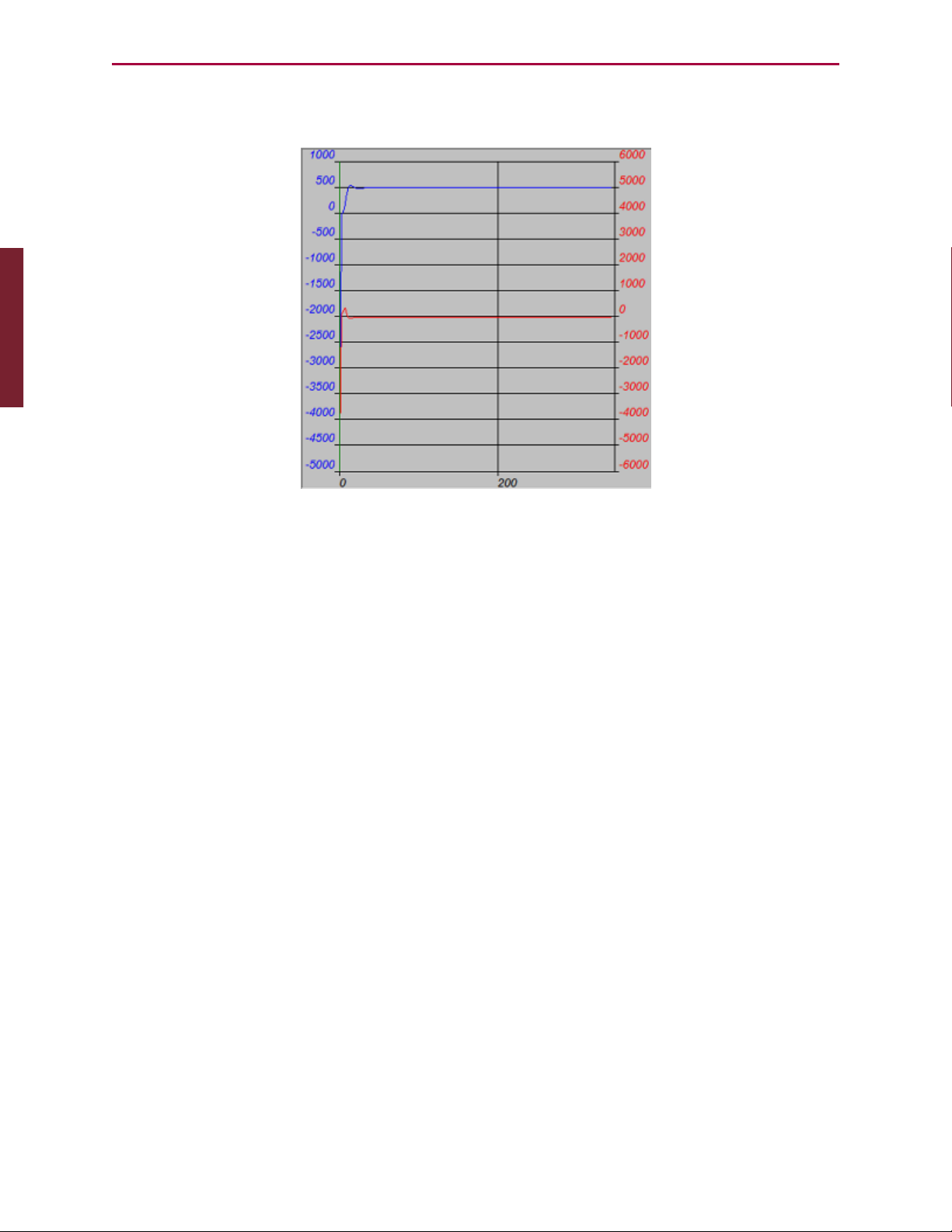
Part 1: Programming: Tuner
If the SmartMotor is connected, is on and is still, you should see results similar to those in the
following figure.
Sample Step Response
The upper curve with the legend on the left is the SmartMotor’s actual position over time.
Notice that it overshot its target position before settling in. Adjusting the PID Tuning will
stiffen the motor up and create less overshoot. For details, see Tuning and PIDControl on
page 231. In a real-world application, there will be an acceleration profile, not a demand for
instantaneous displacement, so significant overshoot will not exist. Nevertheless, it is useful
to look at the worst-case scenario of a step response.
To try a different set of tuning parameters, select the Tuning Values tab to the left of the
graph area. As shown in the following figure, you will see a list of tuning parameters with two
columns: the left column lists what is currently in the SmartMotor; the right column provides
an area to make changes.
Moog Animatics SmartMotor™ Developer's Guide,Rev. L
Page 84 of 909
Page 85

Part 1: Programming: Tuner
Apply New Values Button
To make adjustments to the tuning:
1.
Change the values to those shown in the New column of the previous figure.
2.
Click the "Apply New Values" button, which stores the new values in the SmartMotor.
3.
Click the Run Tuning button at the bottom of the Tuning window.
The motor will jolt again and the results of the step response will overwrite the previous
graph. Normally, this process involves repeated trials, following the procedure outlined in the
section on the PID Filter. For details, see Tuning the PID Control on page 233.
When you are satisfied with the results, the parameters producing the best results can be
added to the top of your program in the SmartMotor, or in applications where there are no
programs in the motors, sent by a host after each power-up. For example, the previous
example's tuning parameters would be set using the following tuning commands:
KP=3000
KI=30
KD=10000
KL=32767
F
Moog Animatics SmartMotor™ Developer's Guide,Rev. L
Page 85 of 909
Page 86

Part 1: Programming: SMIOptions
SMIOptions
NOTE: In addition to the software information in this section, there is context-
sensitive help available within the SMI software interface, which is accessed by
pressing the F1 key or selecting Help from the SMI software main menu.
The SMI software has a variety of options that can be customized through the Options window.
It contains tabs and selections for customizing the Scanner, Editor, Terminal and more.
To open the Options window, select:
Tools > Options
The Options window opens, as shown in the following figure.
Options Window
To use the Options window:
l Click a tab to select the options you wish to edit.
l
Consider the default firmware version. Because different SmartMotor firmware versions
have subtle differences, the program scanner needs to know which firmware is being
used to distinguish between supported and unsupported commands.
l
Other options, such as Editor syntax colors, deal with user preferences.
l After you have finished editing options, click OK to close the window and save your
changes.
Moog Animatics SmartMotor™ Developer's Guide,Rev. L
Page 86 of 909
Page 87

Part 1: Programming: SMIHelp
SMIHelp
The most complete and current information available for the SMI software is available within
the program’s extensive Help tool. For details, see the SMI software help.
Context-Sensitive Help Using F1
l
Dialog and Message box: Just press the F1 key while the box is displayed.
l
Information View: Select the line and press the F1 key. The software shows a
description of the selected error. For more details, see Information Window on page 65.
l
Menu command: Select the menu item and press the F1 key.
l
Keyword Information: In the Program Editor, select the keyword and press F1. The
software shows a full description of the selected keyword.
Context-Sensitive Help Using the Mouse
There is a "context help" button on the tool bar. When you click the button (or press Shift+F1
on keyboard) the program enters the Help Mode and the cursor shape changes to context-
sensitive help cursor ( ). In Help Mode you can use the mouse or keyboard to select a menu
command, a toolbar button, an error message in the Information View, or other items within
SMI, and help on the item is displayed.
Help Buttons
You can click the Help button, available on many dialog boxes, to get help about that dialog
box.
Hover Help
You can place (hover) the mouse pointer over an SMI software button or a Program Editor
keyword to see a short description of that button or keyword.
Table of Contents
To see the list of topics within SMI software Help, use the Contents command in the Help
menu.
Moog Animatics SmartMotor™ Developer's Guide,Rev. L
Page 87 of 909
Page 88

Part 1: Programming: Projects
Sample Help Page
Projects
NOTE: In addition to the software information in this section, there is context-
sensitive help available within the SMI software interface, which is accessed by
pressing the F1 key or selecting Help from the SMI software main menu.
In applications with more than one SmartMotor, and possibly more than one program or
communications port, it is helpful to organize all of the elements as a Project rather than deal
with individual files.
NOTE: When working with multiple motors, programs or ports, a Project provides
a convenient way of organizing and using all of the individual elements.
To create a project, from the SMI software main menu, select:
File > New Project
The New Project window opens.
Moog Animatics SmartMotor™ Developer's Guide,Rev. L
Page 88 of 909
Page 89

Part 1: Programming: SmartMotor Playground
To use the New Project window:
l
Enter a name and location in the Project Name and Location fields to title the project
and specify the location where it will be saved.
l
Click OKto save the information. At this point, you have the option of letting the SMI
software explore the network of motors and set up the project automatically, or of
doing it manually by double-clicking on the specific communication ports or motors
listed in the Information window. Unless you are you are a system expert and know
exactly what the port and motor settings are, you should let the software detect the
motors for you.
l
From here, you can open one or more programs for editing in the SMIEditor.
l
After the project is set up, select File > Save Project to save it. Projects are saved as
.SPJ files.
l
To open a project, select File > Open Project, and then select the desired project
(.SPJ) file. When a project file is opened, all motor communication information,
program editor windows and other elements are restored.
l
Use the File > Recent Projects menu to view and select from the projects you've
most recently edited.
New Project Window
SmartMotor Playground
NOTE: In addition to the software information in this section, there is context-
sensitive help available within the SMI software interface, which is accessed by
pressing the F1 key or selecting Help from the SMI software main menu.
If you are a first-time user, the SmartMotor Playground contains some simple controls to help
you get started with moving the motor. The SmartMotor Playground allows you to
immediately move the motor without any programming.
Moog Animatics SmartMotor™ Developer's Guide,Rev. L
Page 89 of 909
Page 90

Part 1: Programming: Opening the SmartMotor Playground
Opening the SmartMotor Playground
There are two ways to access the SmartMotor Playground:
l
From within the SMI software interface
l
From the Windows Start menu as a stand-alone application.
To access the SmartMotor Playground from the SMI software, in the Configuration window,
right-click the motor you want to move and select SmartMotor Playground from the menu.
SmartMotor Playground (Not Connected)
Click Connect (upper-left area of the window) to connect to the SmartMotor.
Moog Animatics SmartMotor™ Developer's Guide,Rev. L
Page 90 of 909
Page 91

Part 1: Programming: Moving the Motor
SmartMotor Playground (Connected)
Moving the Motor
This procedure assumes that:
l
The SmartMotor is connected to the computer. For details, see Connecting the System
in the SmartMotor Installation & Startup Guide for your motor.
l
The SmartMotor is connected to a power source. (Certain models of SmartMotors
require separate control and drive power.) For details, see Understanding the Power
Requirements in the SmartMotor Installation & Startup Guide for your motor.
l
The SMI software has been installed and is running on the computer. For details, see
Installing the SMISoftware in the SmartMotor Installation & Startup Guide for your
motor.
l
The SmartMotor has been detected and addressed. For details, see Detecting and
Addressing the SmartMotors in the SmartMotor Installation & Startup Guide for your
motor.
In addition to the above items:
l
Verify that all status bits are off, except for the Drive ready bit, as shown in the
previous figure. If needed, use the Clear Flags button to clear any bits that are on.
l The Drive Enable input on the M-series motor must be connected and activated.
l
Verify that Disable Software Limits and Disable Hardware Limits options are set as
shown in the previous figure.
NOTE: The SmartMotor's hardware limits must be grounded or disabled for motion
to occur. Therefore, if your SmartMotor doesn't move when moving the slider or
Moog Animatics SmartMotor™ Developer's Guide,Rev. L
Page 91 of 909
Page 92

Part 1: Programming: Moving the Motor
issuing a motion command, verify that you've either grounded the limits or
selected both Disable Hardware Limits check boxes (located at the lower-right
corner of the screen), as shown in the previous figure.
Within the SmartMotor Playground, you can experiment with the many different modes of
operation. Try the following (see the previous figure for the locations of these items):
l
Click the left and right Jog controls and watch the motor follow.
l
Move the position bar to the left or right and watch the motor follow.
l
Enter a value (negative = counterclockwise; positive = clockwise) in the Destination
box and click Go. Watch the motor shaft move until the position counter (yellow box)
reaches that destination.
While the SmartMotor Playground is useful for moving the motor and learning about its
capabilities, to develop a useful application, you will need to create a program. To learn about
programming the SmartMotor, see Beginning Programming on page 47.
Moog Animatics SmartMotor™ Developer's Guide,Rev. L
Page 92 of 909
Page 93

Part 1: Programming: Communication Details
Communication Details
This chapter provides information on the communications functionality that has been designed
into the SmartMotor.
Introduction 95
Connecting to a Host 96
Daisy Chaining Multiple D-Style SmartMotors over RS-232 97
ADDR=formula 98
SLEEP, SLEEP1 99
WAKE, WAKE1 99
ECHO, ECHO1 100
ECHO_OFF, ECHO_OFF1 100
Serial Commands 101
OCHN(type,channel,parity,bit rate,stop bits,data bits,mode,timeout) 101
CCHN(type,channel) 102
BAUDrate, BAUD(channel)=formula 102
PRINT(), PRINT1() 102
SILENT, SILENT1 103
TALK, TALK1 103
a=CHN(channel) 103
a=ADDR 104
Communicating over RS-485 104
Using Data Mode 104
CAN Communications 107
CADDR=formula 107
CBAUD=formula 107
=CAN, =CAN(arg) 107
CANCTL(function,value) 107
SDORD(...) 108
SDOWR(...) 108
NMT 109
RB(2,4), x=B(2,4) 109
Exceptions to NMT, SDORD and SDOWR Commands 109
I/O Device CAN Bus Master 110
Moog Animatics SmartMotor™ Developer's Guide,Rev. L
Page 93 of 909
Page 94

Part 1: Programming: Communication Details
Combitronic Communications 111
Combitronic Features 112
Other Combitronic Benefits 112
Program Loops with Combitronic 112
Global Combitronic Transmissions 113
Simplify Machine Support 113
Combitronic with RS-232 Interface 113
Other CANProtocols 115
CANopen - CAN Bus Protocol 115
DeviceNet - CAN Bus Protocol 115
I²C Communications (D-Style Motors) 115
OCHN(IIC,1,N,baud,1,8,D) 117
CCHN(IIC,1) 117
PRINT1(arg1,arg2, … ,arg_n) 117
RGETCHR1, Var=GETCHR1 117
RLEN1, Var=LEN1 117
Moog Animatics SmartMotor™ Developer's Guide,Rev. L
Page 94 of 909
Page 95

Part 1: Programming: Introduction
Introduction
There are various ways to communicate with a SmartMotor:
l
Direct-command serial over RS-232 or RS-485 (depending on the motor)
l
Data mode
l
Combitronic, CANopen, DeviceNet, etc.
l
I²C communications
NOTE: When using I²C, the SmartMotor is always the bus master. You cannot
communicate between SmartMotors through I²C.
These communications methods are described in the following sections.
In applications using more than one SmartMotor, the best choice for communications is to link
the SmartMotors together over their optional CAN ports, and then communicate with the
group through any of the RS-232 or RS-485 ports of any of the motors on the chain. The
SmartMotor's CAN-based Combitronic communications unifies all SmartMotor data and
functions in a group, which makes any single motor look like a multi-axis controller from the
perspective of the RS-232 or RS-485 ports. Additionally, this allows all the motors to share
resources as though they were a large multi-axis controller.
Moog Animatics offers adapters for
converting RS-232 to RS-485, and for
converting either to USB.
NOTE: If you are unable to communicate with the SmartMotor, you may be able to
recover communications using the Communication Lockup Wizard, which is on the
SMI software Communications menu. For details, see the SMI software online help,
which is accessed by pressing the F1 key or selecting Help from the SMI software
main menu.
Communication Menu - Communication Lockup Wizard
Moog Animatics SmartMotor™ Developer's Guide,Rev. L
Page 95 of 909
Page 96

Part 1: Programming: Connecting to a Host
Connecting to a Host
The default mode for communicating with a Class 5 D-style SmartMotor is serial RS-232;
Class 5 M-style SmartMotors use serial RS-485.
NOTE: The Class 5 M-style motors have one RS-485 and one CAN port; they do not
have an RS-232 port.
The most common and cost-effective solution is through RS-232 serial communications.
Under this structure, each motor is placed in an electrical serial connection such that the
transmit line of one motor is connected to the receive line of the next. Each motor is set to
echo incoming data to the next motor down with approximately 1 millisecond propagation
delay. There is no signal integrity loss from one motor to the next, which results in highlyreliable communications.
NOTE: To maximize the flexibility of the SmartMotor, all serial ports are fully
programmable with regard to bit rate and protocol.
There is a 31-byte input buffer for the RS-232 port and another for the RS-485 port. These
buffers ensure that no arriving information is ever lost. However, when either port is in data
mode, it is the responsibility of the user program within the SmartMotor to keep up with the
incoming data.
Connection Between a SmartMotor and Host PC
The CBLSM1-3M cable
makes quick work of connecting to your first
RS-232-based SmartMotor. It combines the connections for
communications and
power into one cable
assembly.
Moog Animatics SmartMotor™ Developer's Guide,Rev. L
Page 96 of 909
Page 97

Part 1: Programming: Daisy Chaining Multiple D-Style SmartMotors over RS-232
By default, the primary channel, which shares a connector with the incoming power in some
versions, is set up as a command port with the following characteristics:
Also, note the following:
l
If the cable used is not provided by Moog Animatics, make sure the SmartMotor's power
and RS-232 connections are correct.
CAUTION: Be sure to use shielded cable to connect RS-232 ports, with the
shield ground connected to pin 5 (ground) of the PC end only.
l
Buffers on both sides mean there is no need for any handshaking protocol when
commanding the SmartMotor.
l
Most commands execute in less time than it takes to receive the next one. Therefore, be
careful to allow processes time to complete, particularly for slower processes like
printing to an LCD display or executing a full subroutine.
Default
Other
Options
Type: RS-232 RS-485
Parity: None Odd or Even
Bit Rate: 9600 2400 to 115200
Stop Bits: 1 0 or 2
Data Bits: 8 7
Mode: Command Data
Echo: Off On
Daisy Chaining Multiple D-Style SmartMotors over RS-232
This section describes how to daisy chain multiple D-style SmartMotors to a single RS-232
port as shown in the following figure. Other SmartMotors can be connected together in a
daisy-chain or multi-drop fashion. For details, see Connecting the System in the SmartMotor
Installation & Startup Guide for your motor.
For low-power motors (size SM23165D and smaller), as many as 100 motors could be
cascaded using the daisy-chaining technique for RS-232. To operate independently, each
motor must be programmed with a unique address. In a multiple-motor system, the
programmer has the choice of putting a host computer in control or having the first motor in
the chain be in control of the rest.
Moog Animatics SmartMotor™ Developer's Guide,Rev. L
Page 97 of 909
Page 98

1 1 1 1
2
3
4
5
A1
A2
2
3
4
5
2
3
4
5
2
3
4
5
A1
A2
I/O-6
+5VDC Out
RS-232 Tx
RS-232 Rx
RS-232 GND
Servo Power (+)
Power GND
I/O-6
+5VDC Out
RS-232 Tx
RS-232 Rx
RS-232 GND
Servo Power (+)
Power GND
DE9 Female POWER
Attach shield at PC end
Motor: 1 2 3 4
A1A1
A2A2
5 1
9 6
Part 1: Programming: ADDR=formula
The following are related commands. For more details on these commands, see Part 2:
SmartMotor Command Reference on page 238.
ADDR=formula
Set Motor to New Address
The ADDR= command causes a SmartMotor to respond exclusively to serial commands
addressed to it. It is separate and independent of the motor's CAN address. The address
Daisy-Chain Connection between SmartMotor and Host PC
NOTE: You can build your own RS-232 daisy-chain cable or purchase Add-A-Motor
cables from Moog Animatics.
Fully-molded Add-A-Motor
cables make quick work of
daisy-chaining multiple motors
over an RS-232 network.
CAUTION: Large (size 23 or size 34) SmartMotors draw
so much power that reliable communications often
require isolated communications. For such applications,
consider using the Moog Animatics DIN Rail RS-232
fanout.
Moog Animatics SmartMotor™ Developer's Guide,Rev. L
Page 98 of 909
Page 99

Part 1: Programming: SLEEP, SLEEP1
number range is from 1 to 120.
When each motor in a chain has a unique address, an individual motor communicates
normally after its address is sent over the chain one time. To send an address, add 128 to its
value and output the binary result over the communication link. This puts the value above the
ASCII character set, which differentiates it from all other commands or data. The address
needs to be sent only once until the host computer, or motor, wants to change it to something
else.
Sending out an address zero (128) causes all motors to listen and is an efficient way to send
global data such as a G for starting simultaneous motion in a chain. Once set, the address
features work the same for RS-232 and RS-485 communications.
RS-232 Daisy-Chained SmartMotors
Unlike the RS-485 star topology, the consecutive nature of the RS-232 daisy chain creates the
opportunity for the chain to be independently addressed entirely from the host, rather than by
having a uniquely-addressed program in each motor. Setting up a system this way adds
simplicity because the program in each motor can be exactly the same. If the RUN? command
is the first in each of the motor’s programs, the programs will not start when the SmartMotor
power is turned on. Addressing can then be worked out by the host before the programs are
later initiated through a global RUN command.
SLEEP, SLEEP1
Assert sleep mode
WAKE, WAKE1
De-assert SLEEP
The SLEEPcommand causes the motor to ignore all commands except the WAKE command.
This feature can often be useful, particularly when establishing unique addresses in a chain of
motors. The 1 at the end of commands specifies the AniLink RS-485 port.
NOTE: The SmartMotor can be made to automatically ECHO received characters to
the next SmartMotor in a daisy chain
Moog Animatics SmartMotor™ Developer's Guide,Rev. L
Page 99 of 909
Page 100

Part 1: Programming: ECHO, ECHO1
ECHO, ECHO1
ECHO input
ECHO_OFF, ECHO_OFF1
De-assert ECHO
The ECHO and ECHO_OFF commands toggle (turn on/off) the echoing of data input. Because
the motors do not echo character input by default, consecutive commands can be presented,
configuring them with unique addresses, one at a time. If the host computer or controller sent
out the following command sequence, each motor would have a unique and consecutive
address.
If a daisy chain of SmartMotors has been powered off and back on, the following commands
can be entered into the SmartMotor Interface to address the motors (0 equals 128, 1 equals
129, etc.). Some delay should be inserted between commands when sending them from a host
computer.
0SADDR1
1ECHO
1SLEEP
0SADDR2
2ECHO
2SLEEP
0SADDR3
3ECHO
0WAKE
Commanded by a user program in the first motor instead of a host, the same daisy chain
could be addressed with the following sequence:
SADDR1'Address the first motor
ECHO'Echo for host data
PRINT(#128,"SADDR2",#13) '0SADDR2
WAIT=10 'Allow time
PRINT(#130,"ECHO",#13) '2ECHO
WAIT=10
PRINT(#130,"SLEEP",#13) '2SLEEP
WAIT=10
PRINT(#128,"SADDR3",#13) '0SADDR3
WAIT=10
PRINT(#131,"ECHO",#13) '3ECHO
WAIT=10
PRINT(#128,"WAKE",#13) '0WAKE
WAIT=10
Moog Animatics SmartMotor™ Developer's Guide,Rev. L
Page 100 of 909
 Loading...